ZONDA HOBBY TECHNOLOGIES ELECTRONIC HK0001 Remote Controller for Toy User Manual GWY004539 GWY 6T V2 Transmitter
ZONDA HOBBY TECHNOLOGIES ELECTRONIC LIMITED Remote Controller for Toy GWY004539 GWY 6T V2 Transmitter
User Manual.pdf
1
GWY004539 6T Transmitter
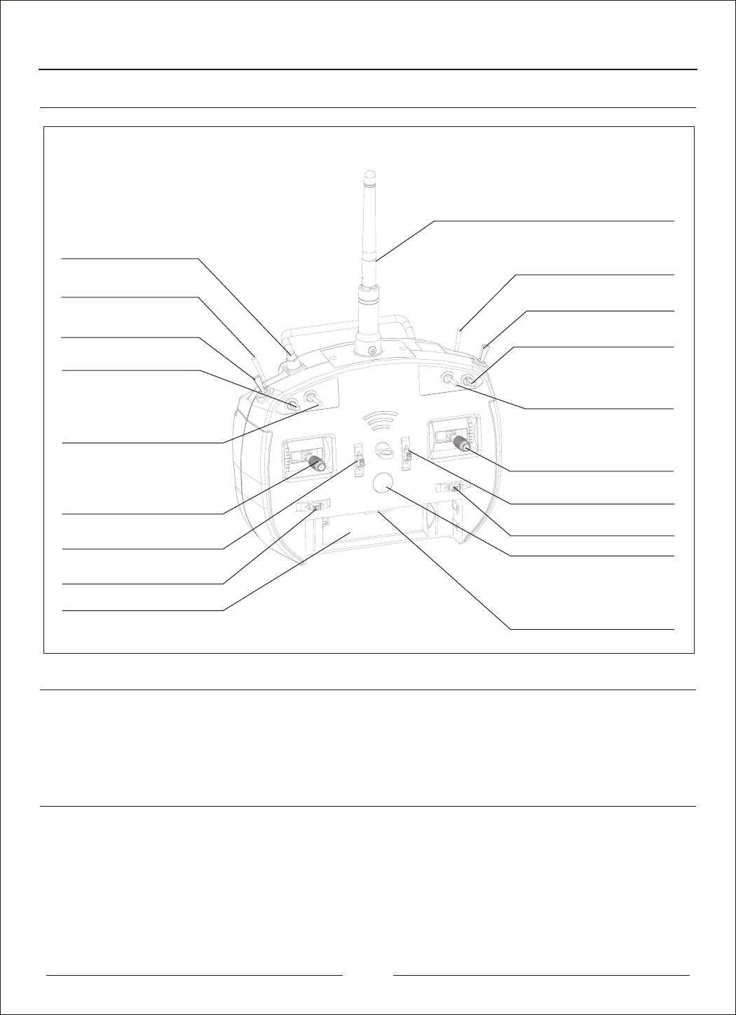
1.Transmitter components introduction
Antenna
Power button
1.LCD setting module connector
2.Wireless Sim USB connector
3.Charging connection wire connector
4.External data connector
Transmitter battery box
Mode 3 / Mode 4 aileron trim
Mode 1 /Mode 3 elevator trim
Mode 2 / Mode 4 throttle trim
Mode3 elevator and aileron stick
Mode4 throttle and aileron stick
Mix / Hold
Aileron D/R
Aux 1
Trainer/Bind
Gear
3D switch (Mode 2/ Mode 4)
Elevator D/R
Flap Gyro
2.Transmitter standard and parameters
1)The frequency bandwidth: ISM 2.4GHz (2.400~2.480GHz)
2)number of controller is 6CH
3)The current is not greater than 100 mA (exclude LCD setting module), not greater than 120 mA
(include LCD screen)
4)The battery is Li-Polymer battery (4.2V), the volume is 1100 mAh
Tail Blade pitch (Mode 1/ Mode 3)
3D switch (Mode 1/ Mode 3);
Tail Blade pitch (Mode2 /Mode 4)
Mode1 elevator and rudder stick
Mode2 throttle and rudder stick
Mode 1 / Mode 2 rudder trim
Mode3 throttle and rudder stick
Mode4 elevator and rudder stick
Mode1 throttle and aileron stick
Mode2 elevator and aileron stick
Mode 1 /Mode 3 throttle trim
Mode 2 / Mode 4 elevator trim
Mode 3 / Mode 4 rudder trim
Mode 1 / Mode 2 aileron trim
1)
2)
3)
4)
5)
6)
7)
The transmitter is using 2.4G ISM frequency channel, allow auto detection while using the transmitter.
The transmitter receive or distribute the frequency by ID identify technology, protect external jamming,
provide stable and reliable during the operation.
The LCD setting module is dividable, user-friendly and setting the trim easily.
Interchanging interface easily (Change Mode + Menu setting)
Trainer connector is using wireless technology
The power button is using soft material to become the button, it is durable and change the connection
defect while pushing the roller power button
The transmitter is based on the ergonomic technology to design the transmitter
3.Product Features
2
1
2
3
4
Right Throttle to Left Throttle (Mode 1/Mode 3 to Mode 2/ Mode 4)
Use a cross-drive screw driver to loosen Screw D. Keep loosening until the stick can move up and down
without friction.
1)Tighten Screw C. Keep tightening until the stick can move up and down with rebounds.
Loosen Screw B. Keep loosening until the stick can move up and down without rebounds
Tighten Screw A. Keep tightening until the stick can move up and down with friction
Back view of Transmitter
MODE 1
Rudder Stick
Elevator Stick
Aileron Stick
Throttle Stick
MODE 2
Rudder Stick
Elevator Stick
Aileron Stick
Throttle Stick
MODE 3
Rudder Stick
Elevator Stick
Aileron Stick
Throttle Stick
MODE 4
Rudder Stick
Elevator Stick
Aileron Stick
Throttle Stick
2
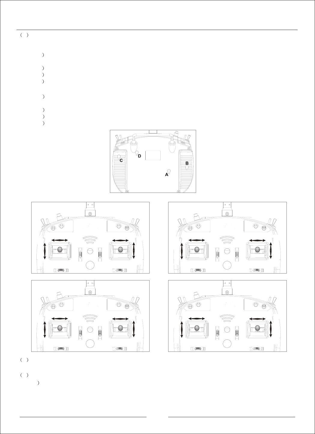
Set Control Mode, change of control mode
There are 4 Control Modes: Mode 1, Mode 2, Mode 3 and Mode 4, as shown in the above
3
Changing control mode
4.Interchanging position of throttle and elevator control
1
1
2
3
4
Structural adjustment: Before the adjustment, please take out the four rubber pistons (A, B, C and D) on the back
of the transmitter, as shown in the figure
Left Throttle to Right Trottle (Mode 2/Mode 4 to Mode 1/ Mode 3)
Use a cross-drive screw driver to loosen Screw A. Keep loosening until the stick can move up and down
without friction
Tighten Screw B. Keep tightening until the stick can move up and down with rebounds
Loosen Screw C. Keep loosening until the stick can move up and down without rebounds
Tighten Screw D. Keep tightening until the stick can move up and down with friction
1
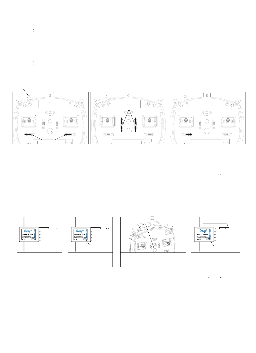
Push and hold both the R/A Trim (Rubber/Aileron Trim) leftward at the same time then press the Bind button.
The transmitter will emit a series of beep sound. That indicates the transmitter has entered the control mode
setting.
3
5.Normal instruction
1)
2)
Turn on transmitter procedure: Press and hold the power button 3~5 second, the buzzer will have a beep noise, the
LCD icon will light on and solid. This signal means the transmitter is turn on successfully.
Binding procedure: Insert the binding plug in the Channel 9 (Power supply interface) receiver / 3 axis gyro and connect
the electricity, the LED will fast flashing. Pressing and holding the transmitter binding button and power on the transmitter.
When the transmitter was power on, you should release the power button first and wait for 10 seconds after, release the
binding button lastly. If the above procedure is success, the LED will solid after 5 seconds and the binding process is
completed, remove the binding plug. Otherwise, please follow the above procedure to bind it again. (Note: To operate the
binding procedures, please make sure the brushless motor and the ESC is not connected.)
LED fast flashing
LED fast flashing
3)
4)
5)
Turn off transmitter procedure: Press and hold the power button 3~5 second, the buzzer will have a beep noise, the
LCD icon will light off and solid. This signal means the transmitter is turn off successfully.
Trainer wireless binding: Open the transmitter (Master transmitter), plug in the wireless connection device through the
30 Pin connector, after that press and hold the binding button, it will auto detect the wireless connection device and
connect with the transmitter in 20 seconds. If success, the LED wireless connection device will solid.
Charging procedure: Plug in the charging connection wire to the transmitter via the 30 Pin charging connector, and then
plug the USB connector in the 5V charger.
Remove the binding plug
Pressing and holding the transmitter binding
button and power on the transmitter. When the
transmitter was power on, you should release
the power button first and wait for 10 seconds
after, release the binding button lastly
Jack in the binding plug
Press the Binding button and the power
button at the same time
LED steady light
LED steady light, Remove the
binding plug
2
3
Select your desired control mode by pushing the T/E Trim (Throttle/Elevator Trim) as instructions and picture
shown below:
Push the right T/E Trim upward for MODE 1, one beep sound will be emitted.
Push the right T/E Trim downward for MODE 2, two beeps will be emitted.
Push the left T/E Trim upward for MODE 3, three beeps will be emitted.
Push the left T/E Trim downward for MODE 4, four beeps will be emitted.
After the desired control mode is selected, push the left R/A Trim (Rubber/Aileron Trim) to the right as shown
below in figure 3, corresponded beeping sound as when setting the control mode will be emitted (1 beep for
MODE 1, 2 beeps for MODE 2 etc.), the transmitter will then save the selected control mode and turns off
automatically. The selected control mode will be in use the next time when the transmitter is turned on.
MODE 3
MODE 4
MODE 1
MODE 2
T/E Trim
R/A(RUDD/AILE)
BIND
R/A(RUDD/AILE)
Figure 3
Power button
Figure 2Figure 1

4
When the transmitter is opened the aerobatics mode, the helicopter is under the 3D aerobatics mode. In this
mode, the throttle curve is remain at 100% and becomes a V shape status. If the throttle curve change from
0% to 100%, the pitch curve change from -10.5 degrees to +10.5 degrees (factory default setting). This is the
preferred flight mode for aerobatics flight. (The user can use the GWY setting module or connection wire to
connect with the computer to reset the pitch and throttle curve)
Pitch Curve
0
+10.5
-10.5
-10.5
Throttle Curve
50%
100%
0%
Normal
When the transmitter is closed the aerobatics mode, the throttle curve is linear from 0% to 100%. The helicopter
under this mode, it will change the setting depends on throttle curve from 0% to 100% and the pitch curve from -3
degrees to +10.5 degrees (factory default setting). This is the preferred flight mode for general hovering and basic
flight. (The user can use the GWY setting module or connection wire to connect with the computer to reset the
pitch and throttle curve)
Aerobatics
Throttle Curve
50%
100%
0%
Bottom High
Throttle Control Stick
Pitch Curve
0
+10.5
-10.5
+10.5
+10.5
6.Normal and aerobatics mode
GWY 6T channel helicopter is installed an aerobatics curve in the transmitter, switch off the transmitter, the pitch and
throttle is automatically exchange into suitable for aerobatics mode used. The picture below: (Left throttle).
F MODE / OFF
F MODE / ON
-3
Bottom High
Throttle Control Stick
Bottom High
Throttle Control Stick Bottom High
Throttle Control Stick
Mode 2
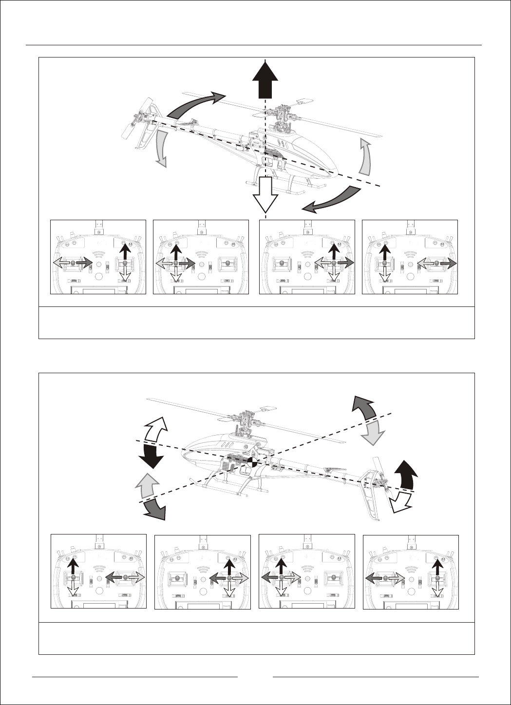
7.The transmitter control instruction
5
Mode 1
Mode 2
Mode 1
Mode 4Mode 3
Mode 4
Mode 3
When the throttle stick is pushing up, the helicopter will increase the speed and flight up. When the throttle stick is
pushing down, the helicopter will decrease the speed and flight down.
When the rudder is pushing left, the helicopter will turn left; when the rudder is pushing right, the helicopter will turn right.
When the elevator is pushing up, the helicopter will flight front; when the elevator is pushing down, the helicopter will flight back.
When the aileron is pushing left, the helicopter will flight left; when the aileron is pushing right, the helicopter will flight right.

8.Trouble Shooting
6
Trouble Description Possible reason Solution
Can not turn on the
transmitter Missing battery or voltage Changing battery and re-charging the battery
Turn on the transmitter,
Buzzer
have noise but can not
turn on the transmitter.
1)Throttle position has not push down to the lowest position.
2)Other functions can not go back to default "0" position.
1)Please check the throttle stick position, push down the stick at
the lowest position.
2)Please check all the functions button or switch, and adjust the
value back to "0" position
Can not connect with
the receiver normally
1)When turn on the transmitter, user press the binding
button carelessly
2)Is there any metal or other material suround with you
3)The helicopter is not charging normally
Remote control area
has not achieve the
standard
The receiver antenna must have a distance with other
electronic wire (at least 20mm)
1)Is it the helicopter type not correct?
2)Is it Servo not working properly?
3)Is there any strong frequency jammed, affecting the
transmission quality?
1)Please make sure the transmitter setting is matching
with the correct helicopter model
2)Please make sure the servo is working properly
3)Please make sure there is no any big frequency device
in the area. It is include wireless router or frequency tower
Under the operation, LED
is flashing unexpectedily,
the Buzzer have noise
contiuously.
The battery power is very low (Lower than 20%)
or connection error, occur the alarm.
Please check the battery stick tight, and then check the
battery power. Charging the battery on time and replace
the battery if necessary.
1)Is the receiver antenna mix with the other device wire
together?
2)Is the receiver antenna loose or damage?
Remote control can not
operate properly
1)Please press the binding button to re-binding the transmitter
2)Please stay in a flat area without heavy or many metals
surounded area
3)Please check the receiver battery power and connector is
connected correctly
FCC ID: 2AAB6-HK0001
Item Number:GWY004539
Zonda Hobby Technologies Electronic Ltd
This device complies with Part 15 of the FCC Rules. Operation is subject to the following two conditions : (1) this
device may not cause harmful interference, and (2) this device must accept any interference received, including
interference that may cause undesired operation.
To comply with FCC s RF radiation exposure limits for general population/uncontrolled exposure, this device
must be operated only in hands with a separation distance of at least 20 cm from its antenna to the body. In add-
ition it must not be collocated or operating in conjunction with any other antenna or transmitter.
Warning: Changes or modifications to this unit not expressly approved by theparty responsible for compliance
could void the user s authority to operate the equipment.
NOTE: This equipment has been tested and found to comply with the limits for a Class B digital device, pursuant
to Part 15 of the FCC Rules. These limits are designed to provide reasonable protection against harmful interfe-
rence in a residential installation. This equipment generates, uses and can radiate radiofrequency energy and,
if not installed and used in accordance with theinstructions, may cause harmful interference to radio communi-
cations.
However, there is no guarantee that interference will not occur in a particular installation. If this equipment does
cause harmful interference to radio or television reception, which can be determined by turning the equipment
off and on, the user is encouraged to try to correct the interference by one or more of the following measures:
Reorient or relocate the receiving antenna.
Increase the separation between the equipment and receiver.
Connect the equipment into an outlet on a circuit different from that to which the receiver is connected.
Consult the dealer or an experienced radio/TV technician for help.
CAUTION
RISK OF EXPLOSION IF BATTERY IS REPLACED
BY AN INCORRECT TYPE.
DISPOSE OF USED BATTERIES ACCORDING
TO THE INSTRUCTIONS
Correct Disposal of this product. This marking indicates that this product should not be disposed with
other household wastes throughout the EU. To prevent possible harm to the environment or human health from
uncontrolled waste disposal, recycle it responsibly to promote the sustainable reuse of material resources. To
return your used device, please use the return and collection systems or contact the retailer where the product
was purchased. They can take this product for environmental safe recycling.
Hereby, ZONDA HOBBY TECHNOLOGIES ELECTRONIC LIMITED, declares that this
GWY004539 is in compliance with the essential requirements and other relevant provisions of
Directive 1999/5/EC