ZTE 880219 ZXSDR CDMA Basestation - 8802 User Manual
ZTE Corporation ZXSDR CDMA Basestation - 8802 Users Manual
ZTE >
Users Manual

ZXSDRBS8802C100
ZXSDRCDMABasestation-8802
UserGuide
Version:1.00
ZTECORPORATION
NO.55,Hi-techRoadSouth,ShenZhen,P .R.China
Postcode:518057
Tel:+86-755-26771900
Fax:+86-755-26770801
URL:http://ensupport.zte.com.cn
E-mail:support@zte.com.cn

LEGALINFORMATION
Copyright©2011ZTECORPORATION.
Thecontentsofthisdocumentareprotectedbycopyrightlawsandinternationaltreaties.Anyreproductionor
distributionofthisdocumentoranyportionofthisdocument,inanyformbyanymeans,withoutthepriorwritten
consentofZTECORPORATIONisprohibited.Additionally,thecontentsofthisdocumentareprotectedby
contractualcondentialityobligations.
Allcompany,brandandproductnamesaretradeorservicemarks,orregisteredtradeorservicemarks,ofZTE
CORPORATIONoroftheirrespectiveowners.
Thisdocumentisprovided“asis”,andallexpress,implied,orstatutorywarranties,representationsorconditions
aredisclaimed,includingwithoutlimitationanyimpliedwarrantyofmerchantability,tnessforaparticularpurpose,
titleornon-infringement.ZTECORPORATIONanditslicensorsshallnotbeliablefordamagesresultingfromthe
useoforrelianceontheinformationcontainedherein.
ZTECORPORATIONoritslicensorsmayhavecurrentorpendingintellectualpropertyrightsorapplications
coveringthesubjectmatterofthisdocument.ExceptasexpresslyprovidedinanywrittenlicensebetweenZTE
CORPORATIONanditslicensee,theuserofthisdocumentshallnotacquireanylicensetothesubjectmatter
herein.
ZTECORPORATIONreservestherighttoupgradeormaketechnicalchangetothisproductwithoutfurthernotice.
UsersmayvisitZTEtechnicalsupportwebsitehttp://ensupport.zte.com.cntoinquirerelatedinformation.
TheultimaterighttointerpretthisproductresidesinZTECORPORATION.
RevisionHistory
RevisionNo.RevisionDateRevisionReason
R1.12011–10–25Updatedthe“FCC&ICSTATEMENT”and“FCCRadiation
ExposureStatement”.
R1.02011–04–25Firstedition
SerialNumber:SJ-20110329145303-001
PublishingDate:2011–10–25(R1.1)

Content
FCC&ICSTATEMENT...................................................................................I
FCCRadiationExposureStatement.............................................................I
AboutThisManual.........................................................................................I
Chapter1SystemDescription..................................................................1-1
1.1SystemBackground...........................................................................................1-1
1.2SystemPosition.................................................................................................1-1
1.3Appearance.......................................................................................................1-2
1.4SystemFunctions...............................................................................................1-3
1.5SystemFeatures................................................................................................1-5
1.6ExternalInterfaces.............................................................................................1-6
1.7StandardsComplied...........................................................................................1-7
Chapter2SystemStructure......................................................................2-1
2.1SystemArchitecture...........................................................................................2-1
2.2PRAStructure....................................................................................................2-2
2.3SignalProcessingFlow......................................................................................2-3
Chapter3Indices........................................................................................3-1
3.1PhysicalIndices.................................................................................................3-1
3.2CapacityIndices.................................................................................................3-1
3.3ReliabilityIndices...............................................................................................3-1
3.4PowerIndices....................................................................................................3-2
3.5T emperatureandHumidity..................................................................................3-2
3.6EnvironmentalClasses.......................................................................................3-2
3.7RFIndices.........................................................................................................3-2
3.8BTSClockTechnicalParameters........................................................................3-6
Chapter4Networking................................................................................4-1
4.1Overview...........................................................................................................4-1
4.2ExistingTransmissionResource..........................................................................4-1
4.3MobileDataNetwork..........................................................................................4-2
4.4PublicNetworkResource....................................................................................4-2
Chapter5Application................................................................................5-1
5.1Overview...........................................................................................................5-1
5.2FamilyCoverage................................................................................................5-1
I

5.3EnterpriseApplication.........................................................................................5-2
5.4HotSpotandBlindAreaCoverage......................................................................5-3
5.5SpecialApplicationsSolution..............................................................................5-3
Chapter6HardwareInstallation...............................................................6-1
6.1SafetyInstruction...............................................................................................6-1
6.1.1SafetyOverview.......................................................................................6-1
6.1.2SafetySymbols........................................................................................6-1
6.1.3SafetySpecications................................................................................6-3
6.2InstallationPreparation.......................................................................................6-6
6.3ChassisInstallation............................................................................................6-6
6.3.1Pole-MountingaZXSDRBS8802C100.....................................................6-6
6.3.2Wall-MountedInstallation........................................................................6-10
6.3.3Ceiling-MountingtheZXSDRBS8802C100.............................................6-15
6.4CableInstallation..............................................................................................6-19
6.5GPSAntennaFeederSystemInstallation..........................................................6-19
6.5.1GPSAntennaInstallation........................................................................6-19
6.5.2GPSFeederCableSelectionPrinciple.....................................................6-25
Figures.............................................................................................................I
Tables............................................................................................................III
Glossary.........................................................................................................V
II
FCC&ICSTATEMENT
ThisdevicecomplieswithPart15oftheFCCRules.Operationissubjecttothefollowing
twoconditions:
1.Thisdevicemaynotcauseharmfulinterference.
2.Andthisdevicemustacceptanyinterferencereceived,includinginterferencethatmay
causeundesiredoperation.
Note:
ThisequipmenthasbeentestedandfoundtocomplywiththelimitsforaClassBdigital
device,pursuanttoPart15oftheFCCRules.Theselimitsaredesignedtoprovide
reasonableprotectionagainstharmfulinterferencewhentheequipmentisoperatedin
acommercialenvironment.Thisequipmentgenerates,uses,andcanradiateradio
frequencyenergyand,ifnotinstalledandusedinaccordancewiththeinstructionmanual,
maycauseharmfulinterferencetoradiocommunications.
Operationofthisequipmentinaresidentialareaislikelytocauseharmfulinterferencein
whichcasetheuserwillberequiredtocorrecttheinterferenceathisownexpense.
Caution!
Changesormodicationstothisunitnotexpresslyapprovedbythepartyresponsiblefor
compliancewillvoidtheuser’sauthoritytooperatetheequipment.Anychangetothe
equipmentwillvoidFCCandICgrant.
ThisequipmenthasbeentestedandfoundtocomplywiththelimitsforaClassBdigital
device,pursuanttotheFCCandICRules.Thisequipmentgenerates,usesandcan
radiateradiofrequencyenergyand,ifnotinstalledandusedinaccordancewiththe
instructions,maycauseharmfulinterferencetoradiocommunications.However,thereis
noguaranteethatinterferencewillnotoccurinaparticularinstallation.
I

II

FCCRadiationExposure
Statement
ThisequipmentcomplieswithFCCradiationexposurelimitssetforthforanuncontrolled
environment.Thisequipmentshouldbeinstalledandoperatedwithminimumdistance4m
betweentheradiator&yourbody.
ThisequipmentgeneratesRFelectromagneticenergyduringtransmitmode.
Thisradioisdesignedforandclassiedas“OccupationalUseOnly”,meaningitmust
beusedonlyduringthecourseofemploymentbyindividualsawareofthehazards,and
thewaystominimizesuchhazards.ThisradioisNOTintendedforusebythe“General
Population”inanuncontrolledenvironment.
ThisradiohasbeentestedandcomplieswiththeFCCRFexposurelimitsfor“Occupational
UseOnly”.
Inaddition,theequipmentcomplieswiththefollowingStandardsandGuidelineswith
regardtoRFenergyandelectromagneticenergylevelsandevaluationofsuchlevelsfor
exposuretohumans:
1.FCCOETBulletin65Edition97-01SupplementC,EvaluatingCompliancewithFCC
GuidelinesforHumanExposuretoRadioFrequencyElectromagneticFields.
2.AmericanNationalStandardsInstitute(C95.1-1992),IEEEStandardforSafetyLevels
withRespecttoHumanExposuretoRadioFrequencyElectromagneticFields,3kHz
to300GHz.
3.AmericanNationalStandardsInstitute(C95.3-1992),IEEERecommendedPractice
fortheMeasurementofPotentiallyHazardousElectromagneticFields–RFand
Microwave.
4.Thefollowingaccessoriesareauthorizedforusewiththisproduct.Useofaccessories
otherthanthose(listedintheinstruction)speciedmayresultinRFexposurelevels
exceedingtheFCCrequirementsforwirelessRFexposure.
I

II

AboutThisManual
Purpose
ThismanualdescribesthefeaturesandoperationofZXSDRBS8802C100CDMAindoor
multi-carrierPicoBaseTransceiverStation.
IntendedAudience
Thisdocumentisintendedfor:
lEngineeringtechnicalengineer
lInstallationengineer
PrerequisiteSkillandKnowledge
Tousethisdocumenteffectively,usersshouldhaveageneralunderstandingoftheCDMA
technology.Familiaritywiththefollowingishelpful:
lcdma2000fundamental
lSoftwarebasicknowledge
WhatisinThisManual
Thismanualcontainsthefollowingchapters.
SectionSummary
Chapter1System
Description
Givesanoverview,function,andinterfacesofZXSDRBS8802C100.
Chapter2System
Structure
DescribesthesystemstructureofZXSDRBS8802C100,including
hardwarestructureandsoftwarestructure.
Chapter3IndicesDescribestheindicesofZXSDRBS8802C100.
Chapter4NetworkingDescribesthenetworkingmodeofZXSDRBS8802C100.
Chapter5ApplicationDescribestheapplicationscenariosofZXSDRBS8802C100.
Chapter6Hardware
Installation
DescribestheinstallationprocedureofZXSDRBS8802C100.
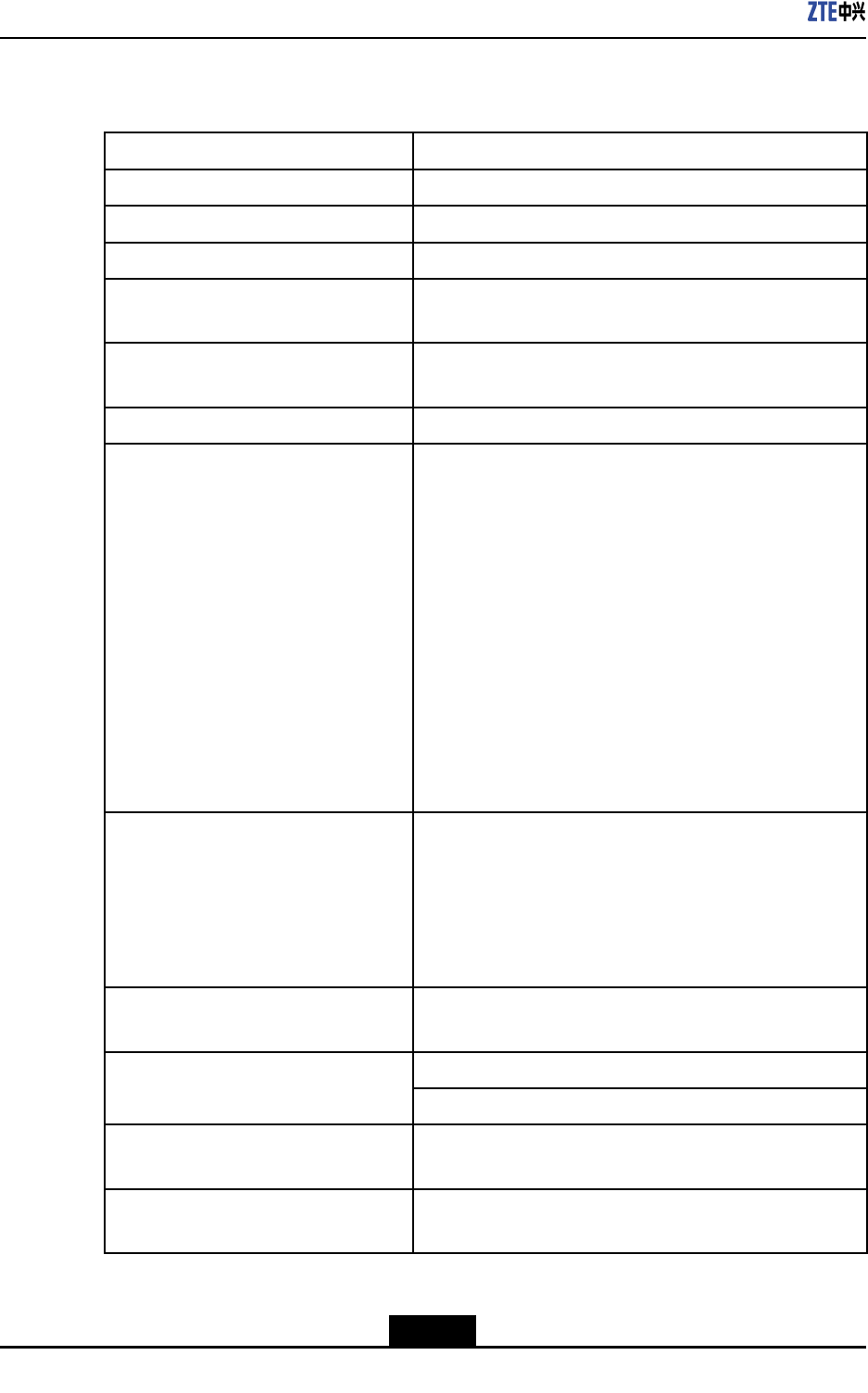
Conventions
ZTEdocumentsemploythefollowingtypographicalconventions.
TypefaceMeaning
ItalicsReferencestootherManualsanddocuments.
“Quotes”Linksonscreens.
I

TypefaceMeaning
BoldMenus,menuoptions,functionnames,inputelds,radiobuttonnames,
checkboxes,drop-downlists,dialogboxnames,windownames.
CAPSKeysonthekeyboardandbuttonsonscreensandcompanyname.
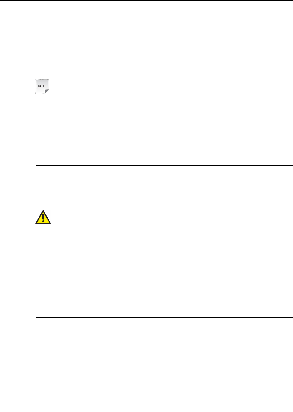
Note:Providesadditionalinformationaboutacertaintopic.
Checkpoint:Indicatesthataparticularstepneedstobecheckedbefore
proceedingfurther.
Tip:Indicatesasuggestionorhinttomakethingseasierormore
productiveforthereader.
II

Chapter1
SystemDescription
TableofContents
SystemBackground...................................................................................................1-1
SystemPosition.........................................................................................................1-1
Appearance................................................................................................................1-2
SystemFunctions.......................................................................................................1-3
SystemFeatures........................................................................................................1-5
ExternalInterfaces.....................................................................................................1-6
StandardsComplied...................................................................................................1-7
1.1SystemBackground
Asa3Gmobilecommunicationsystem,CDMA2000isthemainstreamsystemandwidely
usedinthewholeworld.ItcomprisesMSS,BSS,andMS.BSScomprisesBTSandBSC.
WiththeoptimizationandimprovementofCDMAnetwork,alloperatorsfocusmore
attentiononblindspotcoverageandsupportofenterpriseservices.Incurrentandfuture
networkconstruction,thefocusgoestoenterpriseradioservice,servicebalancinginhot
spots,familyradiocommunication,andotherblindelds,andsolutionandoptimization
schemeforbuildingcoverage.
Underthisbackground,ZTElaunchestheZXSDRBS8802C100PicoCellBTSand
networksolution.ZXSDRBS8802C100isanindoormulti-carrierPicoBaseTransceiver
Station,withlowcostandlowpower.ItisbasedonALL-IParchitecture,whichfacilitates
theconstructionofexiblecross-areanetworkmodesandvirtualwirelessnetwork.
ZXSDRBS8802C100ismainlyusedtocoveraparticularindoorareaandprovide
CDMAserviceaccess.Inaddition,ZXSDRBS8802C100canmanageradioresources
inconjunctionwithremoteBSC.
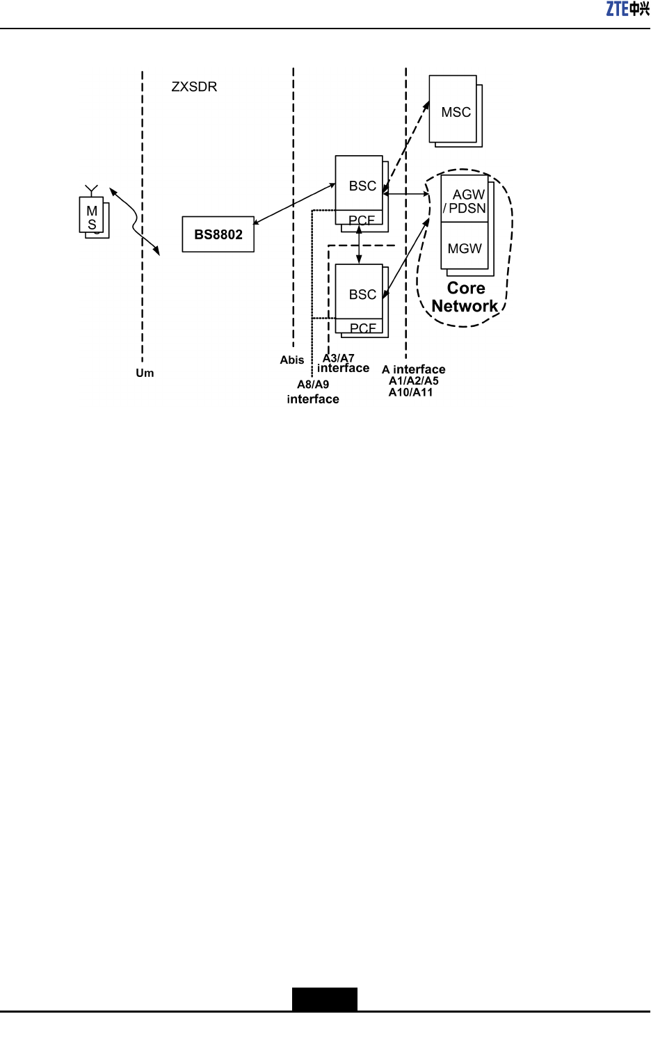
1.2SystemPosition
ZXSDRBS8802C100isanindoormulti-carrierPicoBTS.IntheCDMAmobile
communicationnetwork,itsrelationshipwithotherrelatedentitiesisshowninFigure1-1.
1-1
SJ-20110329145303-001|2011–10–25(R1.1)ZTEProprietaryandCondential
ZXSDRBS8802C100UserGuide
Figure1-1PositionofZXSDRBS8802C100inCDMAsystem
ZXSDRBS8802C100isinthepositionofwirelessaccess,connectingthemobilestation
andBaseStationController(BSC).Itscorrespondingsysteminterfacesare:
lAbisinterface
ZXSDRBS8802C100communicateswithBSCthroughtheAbisinterface.TheAbis
interfaceisaninteriorinterfaceofthesystem,supportingIPOverEthernetinterface.
lUminterface
UminterfaceistheinterfaceconnectingtheaccessterminalATandZXSDRBS8802
C100,followingIS-2000ReleaseAseriesstandardsandIS-856-Astandard.
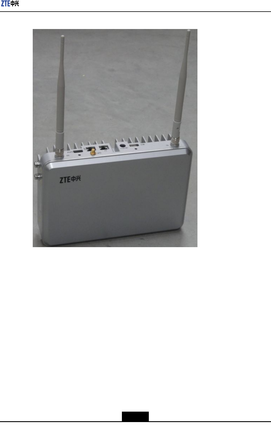
1.3Appearance
Figure1-2showsZXSDRBS8802C100appearance.
1-2
SJ-20110329145303-001|2011–10–25(R1.1)ZTEProprietaryandCondential
Chapter1SystemDescription
Figure1-2ZXSDRBS8802C100Appearance
ZXSDRBS8802C100productisfashionableandgracefulinappearance.Theproduct
coveradoptsengineeringplasticmodulationandthebottomadoptsaluminumalloy
modulation.
1.4SystemFunctions
ZXSDRBS8802C100isasuper-miniIP-basedBTSdesignedwiththeall-IPtechnology,
applicabletoindoorscenarios.BesidesthebasicfunctionsofBTSsuchasbaseband
modulationanddemodulation,RFsignaltransmissionanddemodulation,radioresources
allocation,callprocessing,powercontrolandsofthandoff,itischaracterizedbyauto
IPcapturing,publicnetworktraversing,simpletransmissionbackpath,severalclock
synchronization,andeasyinstallation,etc.
ZXSDRBS8802C100isbasedonall-IPplatformdesign.Asinglesitecansupportthree
carriersandonepseudopilotmaximally,includingone1xcarrier,twoDOcarriers,and
one1xpseudopilot.ItsupportsthebasebandprocessingofCDMA20001Xand1x
EV-DOservices,andtheradiofrequencycapacityof600mW.Byupgradingsoftware,
itcanupgradefromEV-DORev.AtoEV-DORev.B(includingEV-DORev.BPhaseII).
1-3
SJ-20110329145303-001|2011–10–25(R1.1)ZTEProprietaryandCondential
ZXSDRBS8802C100UserGuide
Itisfeaturedbysmallsize,lightweight,lowpowerconsumption,easyinstallation,low
matchingrequirementsandmultipleclocks,etc.Itisapplicabletosmall-capacityindoor
scenarios,andcanbemountedonthewall,poleorceiling,etc.
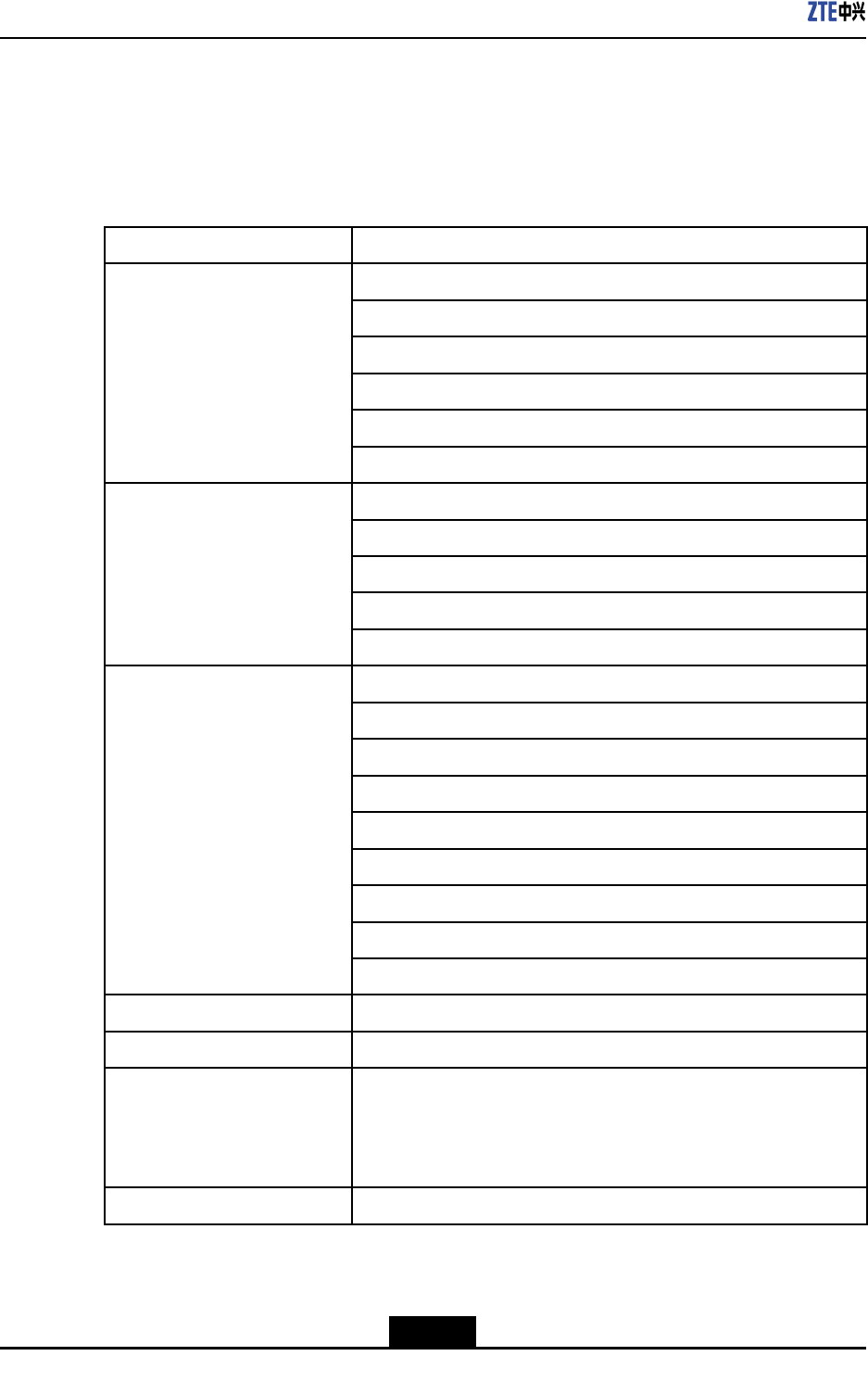
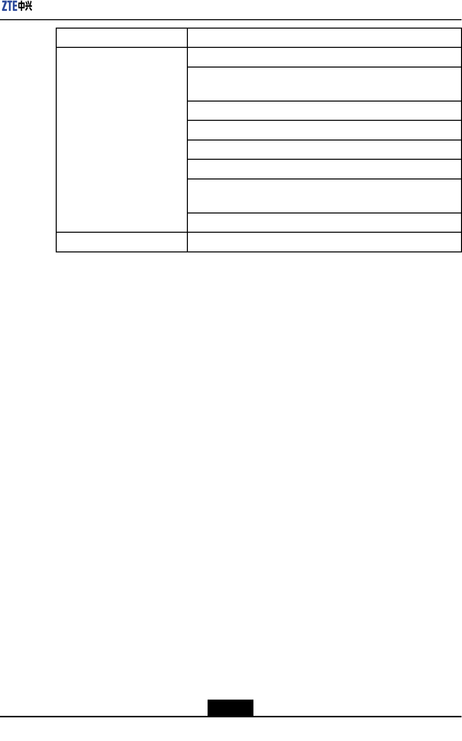
Table1-1showsthemainfunctionsprovidedbyZXSDRBS8802C100.
Table1-1ZXSDRBS8802C100Functions
FunctionCategoryFunctionDescription
Modulation/demodulation
Radioresourcemanagement
Callprocessing
Handoffcontrol
Powercontrol
BasicBasebandFunction
RGPS,GPStimingandsynchronization
Band:800MHz,1.9GHz
RFmodulation/demodulation
RFreceptionandtransmission
LownoiseamplicationforreceivedRFsignal
BasicRFFunction
AmplicationfortransmittedRFsignal
Abisinterface:supportsIPOverEthernetaccess
Airinterface:supportsIS-2000ReleaseAandIS-856-Astandards
Antennainterface:supportsRFtransmissionandreception
Powerinterface:DC12V~13V
LMTinterface:supportslocalmaintenance
GPSinterface:supportsGPS
RGPSinterface:supportsRGPS
USBinterface:reservedinterfacewhichisnotusedatpresent
Interface
RSTinterface:supportshardwarereset
DHCPAutomaticIPobtaining
IPsecSupportingIPsec
IEEE1588
SupportingIEEE1588;ZXSDRBS8802C100canbeusedas
primaryclockserver,whichallocatesclockstootherZXSDR
BS8802C100devicesinthesameEthernet;italsosupportsthe
clocksallocatedbyexternal1588clockserver
NetworkingStar
1-4
SJ-20110329145303-001|2011–10–25(R1.1)ZTEProprietaryandCondential
Chapter1SystemDescription
FunctionCategoryFunctionDescription
Supportslocalmaintenance
Supportsremoteupgradeofsoftwareversionfor
FPGA/BOOT/DSP/CPU
Remotereset,poweroff,andlocalhardresetofserviceboards
Electroniclabel
Powerquery:basebandpower,RFpower
RSSIquery
Poweramplicationcontrolandprotection:over-power,
over-temperatureprotection
EquipmentMaintenanceand
test
Faultself-healing
ScenarioIndoorapplications
1.5SystemFeatures
ZXSDRBS8802C100enablesoperatorstoeasilysolveFeaturesthesignalcoveragein
theresidentialarea,basements,andcommercialofcebuildings,etc.Itistherstchoice
ofoperatorstobuildqualitynetwork,andtosolvethehot-spotareacoverageproblems
quicklywithlowcost,especiallythecoverageproblemscannotsolvedbytraditionalbase
stations.
ZXSDRBS8802C100solutionisforward-lookingandhasfullyconsideredtheactual
requirementsofoperators.Ithasthefollowingcharacteristics:
lSmallsize,lightweight
Itis2.7Linsizeandlessthan2kginweight.Onepersoncaneasilytransport,
carryandinstallit.Itcansavethetransportationandlaborcost,andachievefast
deployment.
lFlexibleinstallation
Itcanbemountedonthewall,pole,orceiling.Theinstallationissimpleandtakeslittle
time.Thesitescanbesetupquickly,greatlyreducingtheengineeringconstruction
fee.
lZerofootprint
Sinceithardlyoccupiesanyindoorspace,thereisnoneedtorentequipmentroom
especially.T omounttheZXSDRBS8802C100onthewall,ceilingorpolecangreatly
reducethefeeonrentingandcoordination.
lLowrequirementsonpowersupply
1-5
SJ-20110329145303-001|2011–10–25(R1.1)ZTEProprietaryandCondential
ZXSDRBS8802C100UserGuide
Itsupports110Vand220VACpowersupply.ItonlyneedstheACsocket,anddoes
notneedadditionalpowersystem.Itcanbeinstalledinsidethebuildingsoflargeand
middlecities.Itneedsnobatteriesasslavepower.
lGPS(orRGPS)distributedinstallation
ForabuildingwithseveralZXSDRBS8802C100devices,onlyoneGPS/RGPSneeds
tobeinstalled.AdoptthepowersplitteroroneZXSDRBS8802C100deviceasmain
server,whichthendistributesclocktootherZXSDRBS8802C100devices.Itissimple
ininstallationandsavesGPS\RGPS,feedercable,andcosts.
lLow-costIPtransmission
ItadoptsEthernetfortransmission,andcanaccessmultipleaccessdevicessuch
asADSL,CableModem,switch,xPON,andsatellitetransmission.Itabandons
expensiveE1/T1andopticbertransmission,greatlysavingtheinvestmentcoston
transmission.
lLargecapacity
Itsupports1xandDOservicessimultaneously,andcanevolvetoEV-DORev.B
throughsoftwareupgrade.
lEnvironmentprotection
Ithassmalltransmissionpowerandlowpowerconsumption,thussavingtheelectricity
fee.ItsatisestheRoSHrequirements.
lEasymaintenanceandoperation
Itsupportsremoteorlocalmaintenance.Themaintenancepersonnelcanupgrade
thesoftwareviaUdisk,andcanmaketroubleshootingthroughtheindicatorlighton
thepanel.
Asfortheindoorcoverage,ZXSDRBS8802C100hasmanyadvantagesandcan
complementtheexistingindoorcoveragesolutions.Itcanhelpoperatorstoraiseindoor
coveragequalityandenhancemarketcompetitiveforceonthefoundationoflow-cost
networking.
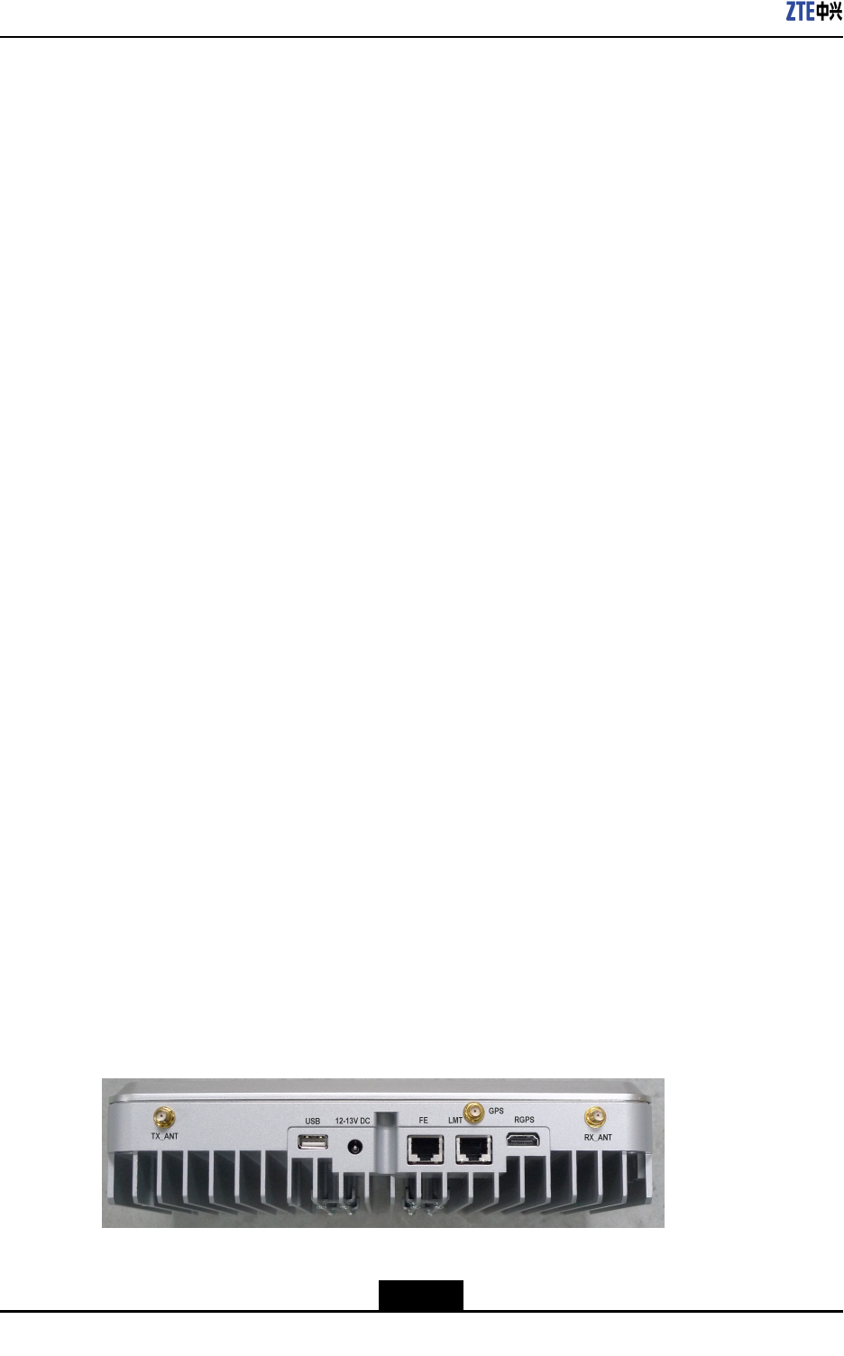
1.6ExternalInterfaces
TheexternalinterfacesofZXSDRBS8802C100arelocatedontherearpanel.Thelayout
isasshowninFigure1-3.
Figure1-3ExternalInterfaces
Table1-2showsadescriptionoftheZXSDRBS8802C100externalinterfaces.
1-6
SJ-20110329145303-001|2011–10–25(R1.1)ZTEProprietaryandCondential
Chapter1SystemDescription
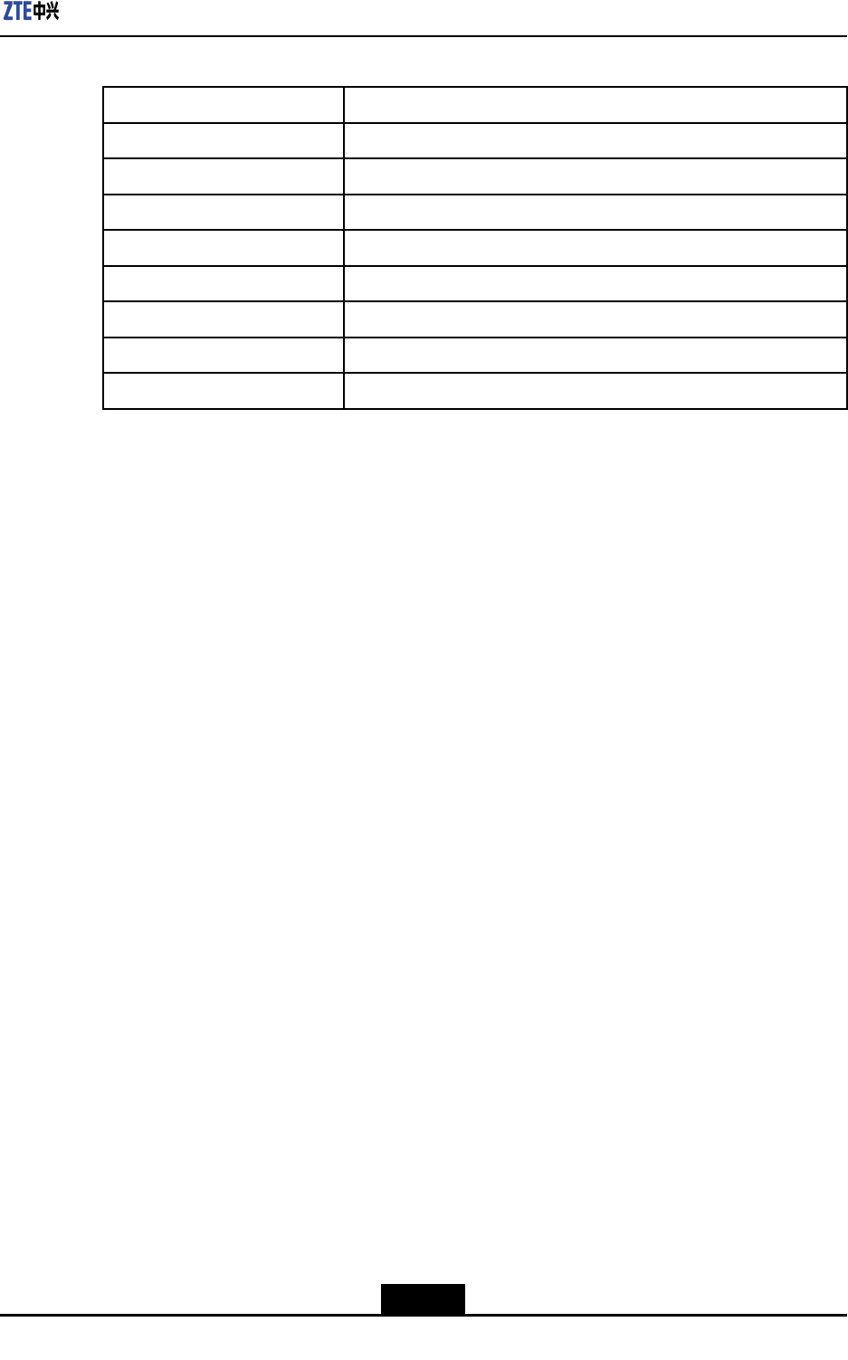
Table1-2ExternalInterfaces
InterfaceDescription
TX_ANTAntennainterfaceforsend
RX_ANTAntennainterfaceforreceive
USBReservedinterfacewhichisnotusedatpresent
FEEthernetinterfaceforAbisinterface
LMTEthernetinterfaceforLMToperationandmaintenance
GPSGPSinterfaceforGPSantenna
RGPSGPSinterfaceforremoteGPSantenna
12–13VDCDCinput
1.7StandardsComplied
ZXSDRBS8802C100complieswiththefollowingstandards:
l3GPP2C.S0063-A,cdma2000HighRatePacketDataSupplementalServices
l3GPP2C.S0063-0,cdma2000HighRatePacketDataSupplementalServices
l3GPP2A.S0008-A.InteroperabilitySpecication(IOS)forHighRatePacketData
(HRPD)RadioAccessNetworkInterfacesWithSessionControlintheAccess
Network
l3GPP2A.S0008(TIA/EIAIS-878),IOSSpecicationforHighRatePacketData
(HRPD)RadioAccessNetworkInterfaces.
l3GPP2C.S0024-B(TIA/EIAIS-856-B):cdma2000HighRatePacketDataAir
InterfaceSpecication
l3GPP2C.S0024(TIA/EIAIS-856):CDMA2000HighRatePacketDataAirInterface
Specication,October2002.
l3GPP2C.S0024-A(TIA/EIAIS-856-A):CDMA2000HighRatePacketDataAir
InterfaceSpecication,August2005.
lCDGRF36,MarkovServiceOptionforWidebandSpreadSpectrumCommunications
Systems.
lTIA/EIA/IS-707-A-2DataServiceOptionsforSpreadSpectrumSystemsAddendum
2,2000.
lTIA/EIA/IS-637,ShortMessageServicesforWidebandSpreadSpectrumCellular
Systems,1997.
lTIA/EIA/IS-95,MobileStation-BaseStationCompatibilityStandardforDual-Mode
WidebandSpreadSpectrumCellularSystems.
lTIA/EIA/IS-127,EnhancedVariableRateCodecSpeechServiceOption3for
WidebandSpreadSpectrumDigitalSystems,1996.
lTIA/EIA/IS-658,DataServiceInterworkingFunctionInterfaceforWidebandSpread
SpectrumSystems.
1-7
SJ-20110329145303-001|2011–10–25(R1.1)ZTEProprietaryandCondential
ZXSDRBS8802C100UserGuide
lTIA/EIA/IS-95-A,MobileStation-BaseStationCompatibilityStandardforDual-Mode
WidebandSpreadSpectrumCellularSystems.
lANSIJ-STD-008,PersonalStation-BaseStationCompatibilityRequirementfor1.8to
2.0GHzCodeDivisionMultipleAccess(CDMA)PersonalCommunicationsSystem,
1996.
lTIA/EIA/TSB-58,AdministrationParameterValueAssignmentsforTIA/EIAWideband
SpreadSpectrumStandards,1995.
l3GPP2C.S0004-Aversion6.0(TIA/EIAIS-2000.4-A-2):SignalingLinkAccess
Control(LAC)SpecicationforCDMA2000SpreadSpectrumSystems-ReleaseA.
lTIA/EIA/IS-725,Over-the-AirServiceProvisioningofMobileStationsinWideband
SpreadSpectrumSystems,1997.
l3GPP2C.S0001-Aversion5.0:IntroductiontoCDMA2000StandardsforSpread
SpectrumSystems-ReleaseA.
lTIA/EIA/TSB-74,Supportfor14.4KbpsDataRateandPCSInteractionforWideband
SpreadSpectrumCellularSystem,1995.
lTIA/EIA/IS-728,Inter-SystemLinkProtocol.
l3GPP2C.S0005-Aversion6.0(TIA/EIAIS-2000.5-A-2):UpperLayer(Layer
3)SignalingStandardforCDMA2000SpreadSpectrumSystems-ReleaseA,
Addendum2.
lTIA/EIA/IS-733,HighRateSpeechServiceOption17forWidebandSpreadSpectrum
CommunicationSystems.
l3GPP2C.S0002-Aversion6.0(TIA/EIAIS-2000.2-A-2):PhysicalLayerStandardfor
CDMA2000SpreadSpectrumSystems-ReleaseA.
l3GPP2C.S0003-Aversion6.0(TIA/EIAIS-2000.3-A-2):MediumAccessControl
(MAC)StandardforCDMA2000SpreadSpectrumSystems-ReleaseA,Addendum
2.
lTIA/EIA/IS-707,DataServiceOptionsforWidebandSpreadSpectrumSystems,
1998.
1-8
SJ-20110329145303-001|2011–10–25(R1.1)ZTEProprietaryandCondential
Chapter2
SystemStructure
TableofContents
SystemArchitecture...................................................................................................2-1
PRAStructure............................................................................................................2-2
SignalProcessingFlow..............................................................................................2-3
2.1SystemArchitecture
Asahighlyintegratedultra-smallbasestation,ZXSDRBS8802C100integratestheradio
frequencypart,basebandsection,powersection,andcontrolsectiontoachievethe
functionsofthewholebasestation.ZXSDRBS8802C100isfeaturedbyhighintegration
andsmallsize.Theproductisforward-lookingandcompetitive.Thesystemdiagramis
shownasFigure2-1.
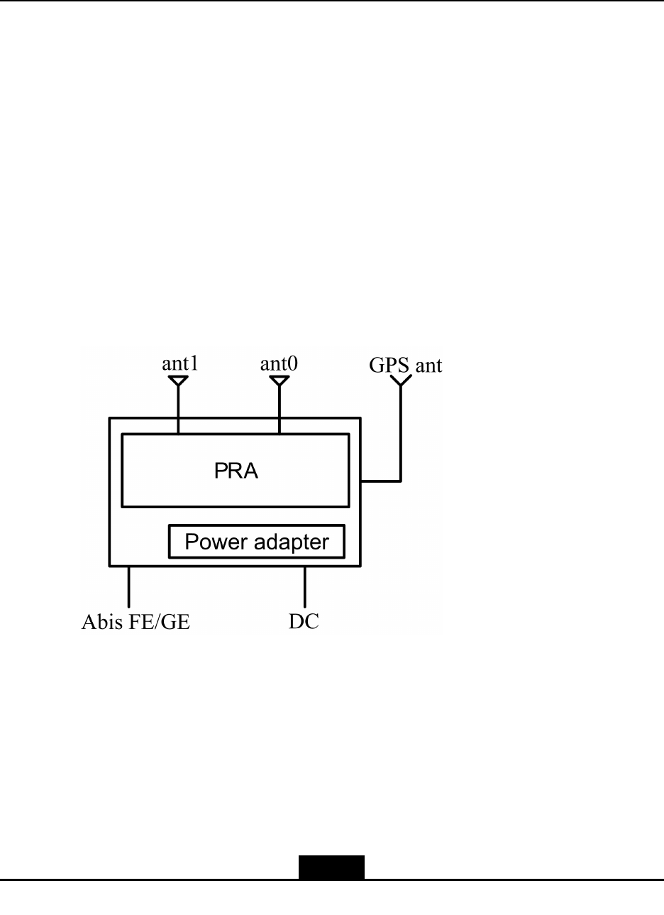
Figure2-1ZXSDRBS8802C100SystemStructure
ZXSDRBS8802C100consistsofPRA,AC-DCpoweradapter,andexternaltransmitting
andreceivingantenna:
lIntegrationunit-PRA
PRAistheunitwithintegratedfunctionssuchascontrol,clock,access,baseband,
andradiofrequency.ItisthecoreunitofZXSDRBS8802C100.
lPoweradapter
ThepowerunitofZXSDRBS8802C100consistsofAC-DCpoweradapterandelectric
cables.
2-1
SJ-20110329145303-001|2011–10–25(R1.1)ZTEProprietaryandCondential
ZXSDRBS8802C100UserGuide
lExternaltransmittingandreceivingantenna
TheexternaltransmittingandreceivingantennaconsistsoftwoindependentRF
antennae.
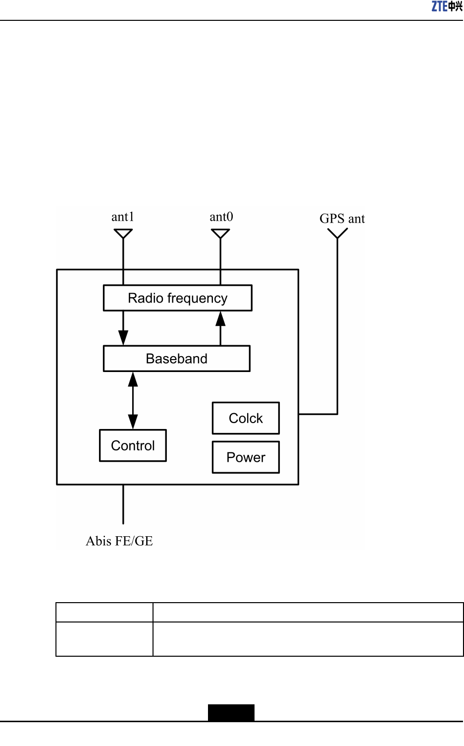
2.2PRAStructure
PRA,asthecoreunitofZXSDRBS8802C100,consistsofradiofrequencyunit,baseband
unit,controlunit,clockunit,andpowerunit.Figure2-2showsthePRAstructureofZXSDR
BS8802C100.
Figure2-2PRAStructure
Table2-1describesthefunctionsofPRAmodules.
Table2-1ZXSDRBS8802C100ModulesandTheirFunctions
NameFunction
RadiofrequencylProvidesRFsignalmodulationanddemodulation;
lProvidestransmissionRFsignalamplication.
2-2
SJ-20110329145303-001|2011–10–25(R1.1)ZTEProprietaryandCondential

Chapter2SystemStructure
NameFunction
Baseband
lProvidesCDMA1XandEV-DOmodulationanddemodulation;
lProvidestheinterfacewithRFlinkandintermediatefrequency
processing.
ControllProvidesFE\GEEthernetaccess;
lProvidescontrolsoverunitsinsidethesystem.
Clock
lReceivesGPSsatellitesignals,providessystemclockandRFreference
clock.
lProvidesvariousclocksusedbythesysteminternally.
PowerProvidessystempowerdistribution.
2.3SignalProcessingFlow
TheinternalsignalprocessingowofZXSDRBS8802C100isasbelow:
lForwardlinkprocessing
ThebusinessdatafromBSCentersthebasebandunitthroughthecontrolunit,and
thenforCDMAmodulationandintermediatefrequencyprocessing.Afterthepower
amplicationofTXunitRFlink,itissenttotheantennafortransmission.
lReverselinkprocessing
ThereverseCDMAsignalsfromtheantennaareconvertedtobasebanddigitalsignal
afterbeingprocessedbyRXunit.Aftersignalprocessing,itisprocessedbythecontrol
unitandpackedintoEthernetframe.ItisnallytransmittedtotheBSCviaEthernet.
2-3
SJ-20110329145303-001|2011–10–25(R1.1)ZTEProprietaryandCondential

ZXSDRBS8802C100UserGuide
Thispageintentionallyleftblank.
2-4
SJ-20110329145303-001|2011–10–25(R1.1)ZTEProprietaryandCondential

Chapter3
Indices
TableofContents
PhysicalIndices.........................................................................................................3-1
CapacityIndices.........................................................................................................3-1
ReliabilityIndices.......................................................................................................3-1
PowerIndices.............................................................................................................3-2
TemperatureandHumidity.........................................................................................3-2
EnvironmentalClasses...............................................................................................3-2
RFIndices..................................................................................................................3-2
BTSClockTechnicalParameters...............................................................................3-6
3.1PhysicalIndices
Dimension:260mm×180mm×58mm(L×W×H)
Weight:lessthan2Kg(standard,excludingpoweradapterandinstallationkits)
3.2CapacityIndices
ZXSDRBS8802C100capacityindicesisshownasT able3-1.
Table3-1ZXSDRBS8802C100CapacityIndices
ItemCarrierssupportedApplication
1
1C1X+2CDO+1Pseudo
PilotSupporting1x,DOrA,DOrBapplications
2
1C1X+1CDO+2Pseudo
PilotsSupporting1x,DOrA,DOrBapplications
32CDO
Onlyapplicabletodataservice,notsupportinghard-
wareupgrade
41C1X+1PseudoPilot
Onlyapplicabletovoiceservice,notsupporting
hardwareupgrade
3.3ReliabilityIndices
lMeanTimeBetweenFailures(MTBF):>100,000hours
lMTTR(MeanTimeToRepair):<0.5hour
lAvailability:>99.999%
3-1
SJ-20110329145303-001|2011–10–25(R1.1)ZTEProprietaryandCondential
ZXSDRBS8802C100UserGuide
3.4PowerIndices
Localpowervoltagerange:85VACto264VAC.
Thetypicalpowerconsumptionis33W.
3.5TemperatureandHumidity
Temperature:-20℃to+45℃.Thechangefrequencymustbelessthan0.5℃/min.
Relativehumidity:5%to95%
3.6EnvironmentalClasses
lGradeOfProtection:IP30.
lGroundingRequirements:Jointgroundingresistanceless1Ω;BTSgrounding
resistanceless5Ω.
lNoise:Noiseofworkingenvironment:less65dBA.
3.7RFIndices
RFindicesoftheZXSDRBS8802C100complywith3GPP2C.S0010-C,Recommended
MinimumPerformanceStandardsforcdma2000SpreadSpectrumBaseStationand
3GPP2C.S0032-A,RecommendedMinimumPerformanceStandardsforCDMA2000
HighRatePacketDataAccessNetwork.
Table3-2illustratesthe800MHztransmitterindices.
Table3-2800MHzTransmitterIndices
NameIndex
Operatingband800MHz(BandClass0)
Transmitteroutputfrequencytolerance±0.01ppm
Occupiedchannelbandwidth1.23MHz(BandClass0)
OutputpowerattheT opofCabinet
(TOC)
600mW
TotaltransmitpowerThetotaltransmitpoweriswithin+2dBand-4dBofthe
manufacturer’sratedpower.
ModulationmodeQuadratureamplitudemodulation
3-2
SJ-20110329145303-001|2011–10–25(R1.1)ZTEProprietaryandCondential
Chapter3Indices
NameIndex
Conductedspuriousemissionand
radiatedspuriousemissionsuppression
<-45dBc@±750kHzoffsetCenterFreq(RBW30kHz)
<-60dBc@±1.98MHzoffsetCenterFreq(RBW30kHz)
>4MHzOFFSET:
<-36dBm(RBW1kHz)@9KHz<f<150KHz
<-36dBm(RBW10kHz)@150KHz<f<30MHz
<-30dBm(RBW1MHz)@1GHz<f<12.5GHz
4-6.4MHzOFFSET:
<-36dBm(RBW1kHz)@30MHz<f<1GHz
6.4MTO16MOFFSET :
<-36dBm(RBW10kHz)@30MHz<f<1GHz
>16MHzOFFSET:
<-36dBm(RBW100kHz)@30MHz<f<1GHz
Transmitterintermodulation
performance
IfoneBTStransmitsattheratedpowerbutanotherBTS’
outputpoweris30dBlessthantheformer’sratedpower.
WhenthepowersoftwoBTSsarecombinedontheantenna
port,thegeneratedintermodulationspuriousemission
meetstheconductedspuriousemissionrequirement.The
IFdifferenceofthetransmitsignalsoftwoBTSsis1.25M.
PilottimetoleranceThePNtimetolerancefallswithin3usandtheinter-carrier
tolerancefallswithin1us.
Timedifference:<±50ns
TimeT olerance/phasetoleranceofpilot
channeltootherchannelsPhasedifference:<0.05rad
WaveformqualityRhoisgreaterthan0.970dBmwithcongurationofa
singlepilot.
PilotcodedomainpowerWiththestandard9CHconguration,thepilotcodedomain
powerisintherangeof-7.0±0.5dB.
InactivechannelcodedomainpowerWiththestandard9CHconguration,theinactivechannel
codedomainpowerislessthan-27dB.
DOMACinactivechannelcodedomain
power
Withcongurationof13FLUSs,theMACinactivechannel
codedomainpowerislessthan-29.5dB(type2).
DODATAchannelcodedomainpower
Withcongurationof13FLUSsattherateof614.44kbs
(test1),theDATAchannelcodedomainpowerisinthe
rangeof-15.5dBto-14.5dB.
Pilotchannel:Rho>0.97
MACchannel:Rho>0.912 WavequalityofDOchannels
DATAchannel:Rho>0.97
RadiofrequencyFrontEndSWR<2.0
3-3
SJ-20110329145303-001|2011–10–25(R1.1)ZTEProprietaryandCondential
ZXSDRBS8802C100UserGuide
Table3-3illustratesthe1.9GHztransmitterindices.
Table3-31.9GHzTransmitterIndices
NameIndex
Operatingband1.9GHz(BandClass1)
Transmitteroutputfrequencytolerance±0.01ppm
Occupiedchannelbandwidth1.25MHz
OutputpowerattheT opofCabinet
(TOC)
600mW
TotaltransmitpowerThetotaltransmitpoweriswithin+2dBand-2dBofthe
manufacturer’sratedpower.
ModulationmodeQuadratureamplitudemodulation
Conductedspuriousemissionand
radiatedspuriousemissionsuppression
<-45dBc@±885kHzoffsetCenterFreq(RBW30kHz)
<-55dBc@±1.98MHzoffsetCenterFreq(RBW30kHz)
>4MHzOFFSET:
<-36dBm(RBW1kHz)@9KHz<f<150kHz
<-36dBm(RBW10kHz)@150kHz<f<30MHz
<-36dBm(RBW100kHz)@30MHz<f<1GHz
4-16MHzOFFSET:
<-30dBm(RBW30kHz)@1GHz<f<12.5GHz
16M-19.2MOFFSET:
<-30dBm(RBW300kHz)@1GHz<f<12.5GHz
>19.2MHzOFFSET:
<-30dBm(RBW1MHz)@1GHz<f<12.5GHz
Transmitterintermodulation
performance
IfoneBTStransmitsattheratedpowerbutanotherBTS’
outputpoweris30dBlessthantheformer’sratedpower.
WhenthepowersoftwoBTSsarecombinedontheantenna
port,thegeneratedintermodulationspuriousemission
meetstheconductedspuriousemissionrequirement.The
IFdifferenceofthetransmitsignalsoftwoBTSsis1.25M.
PilottimetoleranceThePNtimetolerancefallswithin3usandtheinter-carrier
tolerancefallswithin1us.
Timedifference:<±50ns
TimeT olerance/phasetoleranceofpilot
channeltootherchannelsPhasedifference:<0.05rad
WaveformqualityRhoisgreaterthan0.990dBmunderthecongurationof
asinglepilot.
PilotcodedomainpowerWiththestandard9CHconguration,thepilotcodedomain
powerisintherangeof-7.0±0.5dB.
3-4
SJ-20110329145303-001|2011–10–25(R1.1)ZTEProprietaryandCondential

Chapter3Indices
NameIndex
InactivechannelcodedomainpowerWiththestandard9CHconguration,theinactivechannel
codedomainpowerislessthan-27dB.
DOMACinactivechannelcodedomain
power
Withcongurationof13FLUSs,theMACinactivechannel
codedomainpowerislessthan-29.5dB(type2).
DODATAchannelcodedomainpower
Withcongurationof13FLUSsattherateof614.44kbs
(test1),theDATAchannelcodedomainpowerisinthe
rangeof-15.5dBto-14.5dB.
Pilotchannel:Rho>0.97
MACchannel:Rho>0.912 WavequalityofDOchannels
DATAchannel:Rho>0.97
RadiofrequencyFrontEndSWR<2.0
Table3-4illustratesthe800MHzreceiverindices.
Table3-4800MHzReceiverIndices
NameIndex
Operatingband800MHz(BandClass0)
Receiversensitivity<-121dBm
Receiverdynamicrange
Whenthelowerlimitisthereceiversensitivityandthe
upperlimit(noiselevel)equals55dBm/1.23MHz(Eb/N0=
10dB±1dB),theFrameErrorRate(FER)islowerthan1%.
Noisegure<3
Singletonedesensitization
Inthepresenceofasingletonethatis50dBabovethe
CDMAsignallevel,andisatoffsetof±750kHzfromthe
centerfrequency,theoutputpoweroftheMSincreasesby
nomorethan3dB,andtheFERislessthan1.5%.
Inthepresenceofasingletonethatis75dBabovethe
CDMAsignallevel,andisatoffsetof±900kHzfromthe
centerfrequency,theoutputpoweroftheMSincreasesby
nomorethan3dB,andtheFERislessthan1.5%.
Intermodulationspuriousresponse
attenuation
BAND0:
Inthepresenceoftwointerferingtonesthatare60dB
abovetheCDMAsignallevel,andareatoffsetsof+900
kHz,+1.7MHz,-900kHzand-1.7MHzfromthecenter
frequency,theoutputpoweroftheMSincreasesbyno
morethan3dB,andtheFERislessthan1.5%.
Conductedspuriousemissionsand
radiatedspuriousemissions
<-80dBm,measuredwithintheBTSreceiveband
<-60dBm,measuredwithintheBTStransmitband
RadiofrequencyFrontEndSWR<2.0
3-5
SJ-20110329145303-001|2011–10–25(R1.1)ZTEProprietaryandCondential

ZXSDRBS8802C100UserGuide
Table3-5illustratesthe1.9GHzreceiverindices.
Table3-51.9GHzReceiverIndices
NameIndex
Operatingband1.9GHz(BandClass1&14)
Receiversensitivity<-121dBm
Receiverdynamicrange
Whenthelowerlimitisthereceiversensitivityandtheupper
limit(noiselevel)equals-55dBm/1.23MHz(Eb/N0=
10dB±1dB),theFrameErrorRate(FER)islowerthan1%.
Noisegure<3
Adjacentchannelselection(ACS)BandClass6:>-53dBm(±2.5M)
Singletonedesensitization
Inthepresenceofasingletonethatis50dBabovethe
CDMAsignallevel,andisatoffsetof±750kHzfromthe
centerfrequency,theoutputpoweroftheMSincreasesby
nomorethan3dB,andtheFERislessthan1.5%.
Inthepresenceofasingletonethatis75dBabovethe
CDMAsignallevel,andisatoffsetof±900kHzfromthe
centerfrequency,theoutputpoweroftheMSincreasesby
nomorethan3dB,andtheFERislessthan1.5%.
Intermodulationspuriousresponse
attenuation
Inthepresenceoftwointerferingtonesthatare60dB
abovetheCDMAsignallevel,andareatoffsetsof1.25
MHzand2.05MHz,and-1.25MHzand-2.05MHzfrom
thecenterfrequency,theoutputpoweroftheMSincreases
bynomorethan3dB,andtheFERislessthan1.5%.
Conductedspuriousemissionsand
radiatedspuriousemissions
<-80dBm,measuredwithintheBTSreceiveband
<-60dBm,measuredwithintheBTStransmitband
RadiofrequencyFrontEndSWR<2.0
3.8BTSClockTechnicalParameters
lBTSclocktechnicalparameters
Frequencybenchmark:10MHz,inlockedGPSstatus,theaccuracyofthefrequency
issuperiorto10-10;inholdingstatus,theaccuracyofthefrequencyissuperiorto10-10.
Temperaturecharacteristics:<±1×10⁻⁸
lClocksynchronoussource
Iftheclocksynchronoussourceislosttemporarilyorthebasestationclockfallsout
ofstep,tokeeptheshort-termstabilityoftheclock,theHOLDOVERalgorithmcanbe
adoptedtoassurethenormaloperationofthebasestationwhenthesyncsignalgets
lost,sothatthephasedriftwithin4hoursissuperiorto10µs.
3-6
SJ-20110329145303-001|2011–10–25(R1.1)ZTEProprietaryandCondential
Chapter3Indices
lClocksystemperformance
Frequencydifference:<0.05ppm
Phasedifference:<10us
3-7
SJ-20110329145303-001|2011–10–25(R1.1)ZTEProprietaryandCondential

ZXSDRBS8802C100UserGuide
Thispageintentionallyleftblank.
3-8
SJ-20110329145303-001|2011–10–25(R1.1)ZTEProprietaryandCondential
Chapter4
Networking
TableofContents
Overview....................................................................................................................4-1
ExistingTransmissionResource.................................................................................4-1
MobileDataNetwork..................................................................................................4-2
PublicNetworkResource...........................................................................................4-2
4.1Overview
ThetransmissionlinkbetweenZXSDRBS8802C100andBSCusesIPpackets.
Therefore,ZXSDRBS8802C100networkingcanmakefulluseoftherichIPnetwork
resources.Inthisway,theinvestmentondedicatedcircuittransmissionnetworkissaved.
Thefollowingpartdescribesthreenetworkingmodesusingdifferenttransmission
resources.
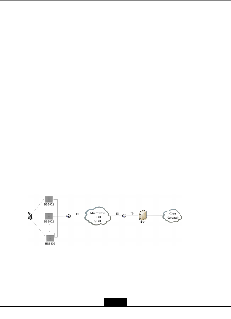
4.2ExistingTransmissionResource
IfthereareidletransmissiontimeslotsbetweentargetcoverageareaandBSC,the
networkingmodeshowninFigure4-1canbeusedtomakefulluseofexistingtransmission
resources.Inactualpractice,asE1transmissionlinkalwaysexistsbetweencoverage
siteandBSC,useapairofG.703-V.35protocolconvertertoconvertIPsignalsandE1
signals.
Figure4-1ExistingTransmissionResource
Advantage:Itguaranteesthetransmissionqualityandutilizestheoperator'sexisting
resources.
Disadvantage:ItdoesnotmakeuseoftheadvantageofIPtransmission,andsignal
conversionintroducesdelayloss.
4-1
SJ-20110329145303-001|2011–10–25(R1.1)ZTEProprietaryandCondential
ZXSDRBS8802C100UserGuide
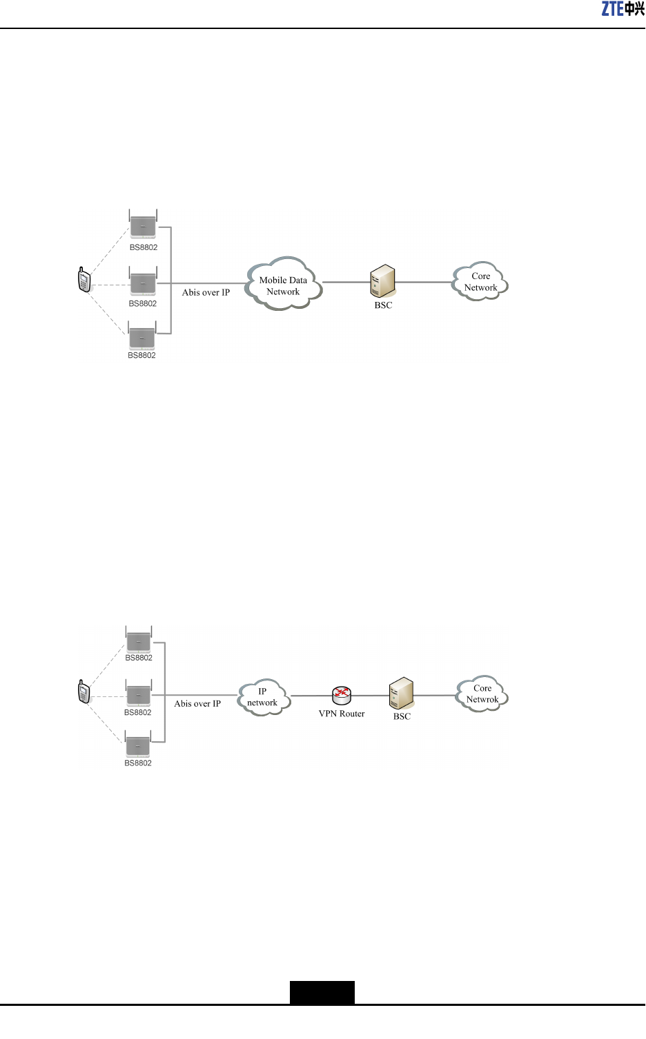
4.3MobileDataNetwork
IftheoperatorshavetheirowndatanetworkbetweenthetargetcoverageareaandBSC,
preferablyusethenetworkingmodeshowninFigure4-2.Inthismode,G.703-V.35
protocolconverterisnotrequiredasboththetransmissionnetworkandsignalstobesent
areinIPmode.
Figure4-2MobileDataNetwork
Advantage:TheQoSisguaranteedduringdatatransmissionsthroughoperator'sowndata
network.
Disadvantage:Fewoperatorshavetheirowndatanetwork.
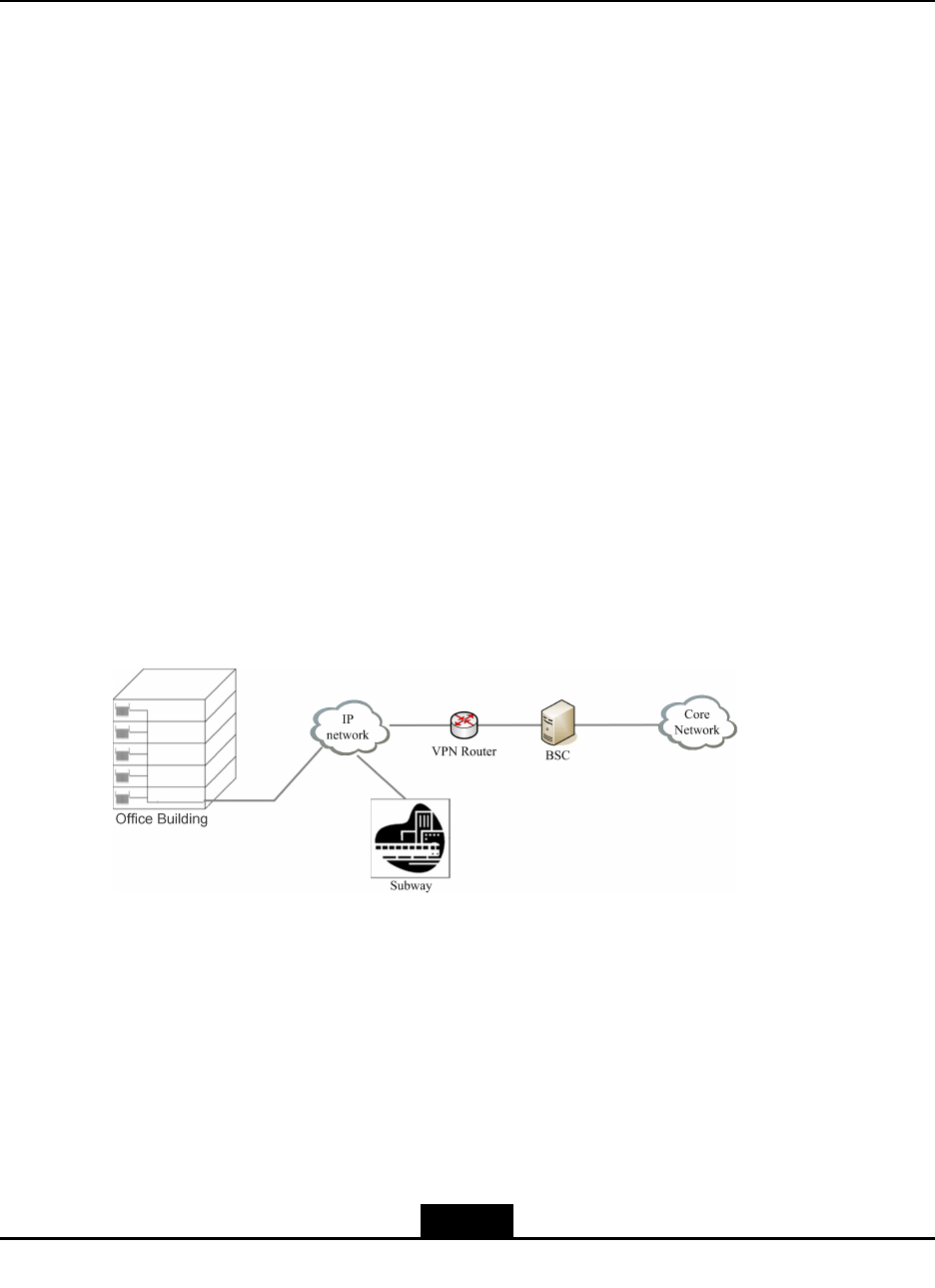
4.4PublicNetworkResource
AsthesignalsareIP-based,ZXSDRBS8802C100canmakefulluseofpublicnetwork
resourcessuchastheInternettotransmitsignals.Thenetworkingmodeisasshownin
Figure4-3.
Figure4-3PublicNetworkResource
Advantage:Flexibleandconvenient,andrichnetworkresources.
Disadvantage:UnstableQoS,asaffectedbynetworkcapacityduetotransmissiondelay
onthepublicnetwork.
4-2
SJ-20110329145303-001|2011–10–25(R1.1)ZTEProprietaryandCondential
Chapter5
Application
TableofContents
Overview....................................................................................................................5-1
FamilyCoverage........................................................................................................5-1
EnterpriseApplication................................................................................................5-2
HotSpotandBlindAreaCoverage.............................................................................5-3
SpecialApplicationsSolution......................................................................................5-3
5.1Overview
Asacompact,highlyeffective,andquietindoorpicocellBTS,ZXSDRBS8802C100is
mainlyusedforindoorcoverage.Itcanbexedonwallandisharmoniouswithvarious
indoordecorationstyles.Moreover,itsultralowpoweroutputmakesitmeetthestrict
environmentprotectionrequirement.
ZXSDRBS8802C100supports1X,EV-DO.Itiscompatiblewithsubsequentevolution
andsupportsbroadbanduserexperience,thusbecomingthepreferredequipmentforcost
effectiveindoorcoverage.
Figure5-1showstheindoorcoveragenetworkingsolution.
Figure5-1IndoorCoverage
Indifferentindoorscenarios,ZXSDRBS8802C100hasdifferentapplications.The
followingpartdescribessometypicalapplicationsolutions.
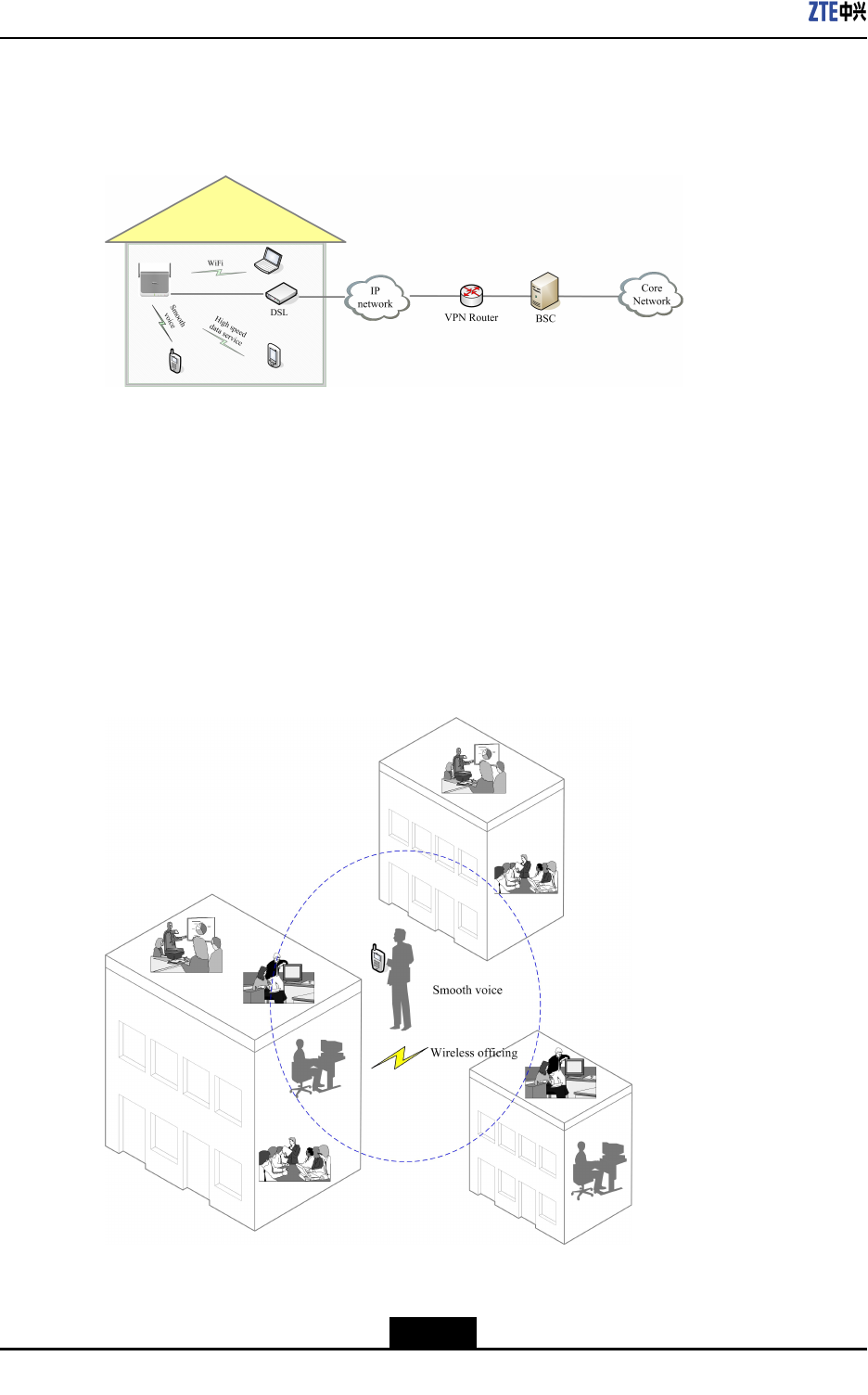
5.2FamilyCoverage
ZXSDRBS8802C100issmall-sized,light,andeasytoinstall.Byutilizingtheexisting
indoorbroadbandsystem,itcaneasilymeettherequirementofcommunityinhabitants
onmultipleservices.Inadditiontoimprovefamilycoverage,itsWLANfunctionenables
ZXSDRBS8802C100toprovideanall-roundhighratedataaccessservicetothefamily.
5-1
SJ-20110329145303-001|2011–10–25(R1.1)ZTEProprietaryandCondential
ZXSDRBS8802C100UserGuide
Therefore,ZXSDRBS8802C100canbeusedasanimportantmeansforfamilycoverage.
Figure5-2showsthesolution.
Figure5-2FamilyCoverage
5.3EnterpriseApplication
Inthissolution,ZXSDRBS8802C100coversenterpriseareawithradiosignalssothat
allemployeesinmotioncanperformcommunicationbasedonvariousservicesinreal
time.Thisfacilitatesthecooperationandfrequentcommunicationofemployeesindifferent
districtsofanenterprisewithlargespan.Withthissolution,variouscustomizedservice
canberealizedinsideanenterprise,suchasintegrateddigitalofceplatform.Figure5-3
showsthesolution.
Figure5-3EnterpriseSolution
5-2
SJ-20110329145303-001|2011–10–25(R1.1)ZTEProprietaryandCondential
Chapter5Application
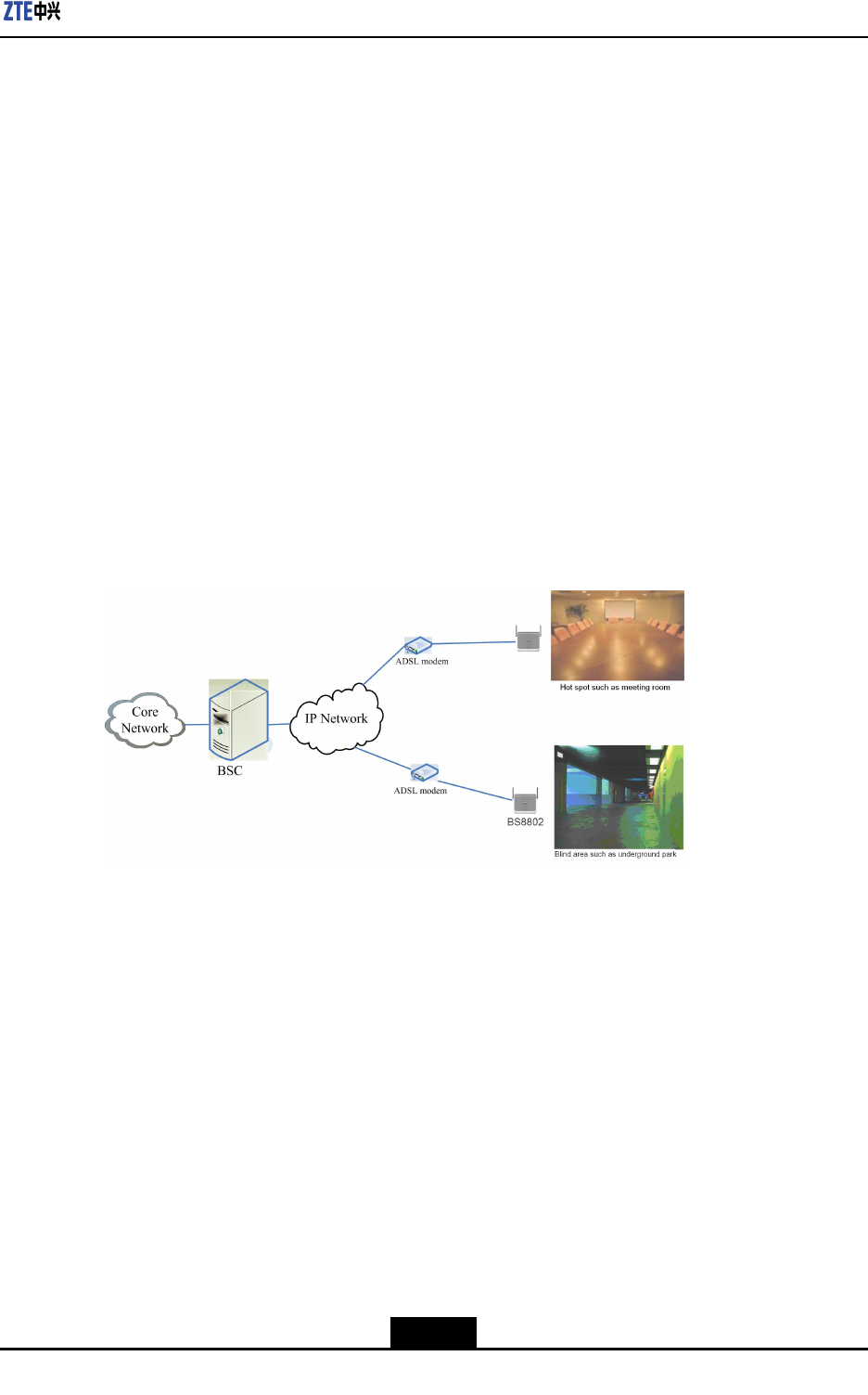
5.4HotSpotandBlindAreaCoverage
ZXSDRBS8802C100hasthefunctionofintelligentfrequencyplanning.Thismakes
ZXSDRBS8802C100agoodsolutionfortemporarilyunblockingtrafccongestionin
hotspots.Throughtheintelligentfrequencysearchfunction,ZXSDRBS8802C100
cantemporallycovertheareaswithtrafcpeakandserveassupplementarynetwork
introduction.Ifhightrafclastsforalongtime,suchmeasuresasmacroBTSreplacement
canbeusedtooptimizethenetworkinthefuture.
Insometrafcbursthotspots,forexample,fairandpromotionactivities,ZXSDRBS8802
C100canbeusedforcoverage.Inareaswithrichnetworkresources,ZXSDRBS8802
C100canreplaceanemergencyvehicle,andinareaswithinsufcientnetworkresources,
ZXSDRBS8802C100canassistanemergencyvehicletorealizeaperfectcoverage.
Inaddition,asZXSDRBS8802C100isexibleandconvenienttohandle,itcanalso
provideperfectsolutioninblindareaswhicharedifculttobecoveredbycommonsolution,
forexample,elevator,undergroundparkinglot,andmetroplatform.
Figure5-4showsthecoverageofhotspotsandblindareas.
Figure5-4HotSpotandBlindAreaCoverage
5.5SpecialApplicationsSolution
Inadditiontotheprevioustypicalapplications,ZXSDRBS8802C100isusedinsome
specialpublicmobilecommunicationsystem,suchasship,train,andairplaneinmotion.
Evenifthedatalinkisofsmallcapacity,ZXSDRBS8802C100canprovideexcellent
mobilecommunicationserviceforthemovingenclosedvehicles.
5-3
SJ-20110329145303-001|2011–10–25(R1.1)ZTEProprietaryandCondential

ZXSDRBS8802C100UserGuide
Thispageintentionallyleftblank.
5-4
SJ-20110329145303-001|2011–10–25(R1.1)ZTEProprietaryandCondential
Chapter6
HardwareInstallation
TableofContents
SafetyInstruction.......................................................................................................6-1
InstallationPreparation...............................................................................................6-6
ChassisInstallation....................................................................................................6-6
CableInstallation......................................................................................................6-19
GPSAntennaFeederSystemInstallation.................................................................6-19
6.1SafetyInstruction
6.1.1SafetyOverview
ReadsafetyinstructionsbeforeinstallationofZXSDRBS8802C100equipment.These
instructionsaresupplementarytolocalsafetyregulationsinplace.Incaseofanyconict,
localsafetyregulationsshallprevail.
Installationpersonnelshouldhavepreliminaryknowledgeaboutsafetyoperationsand
musthavereceivedtrainingoninstallingZTEequipment.
Observerelatedequipmentprecautionsandspecialsafetyinstructionsduring
maintenance,providedbyZTE.
Someimportantsafetyinstructionsarediscussedinthischapter.ZTEshallnotbearany
liabilitiesincurredbyviolationofuniversalsafetyoperationrequirements,orviolationof
safetystandardsfordesigning,manufacturing,andequipmentusage.
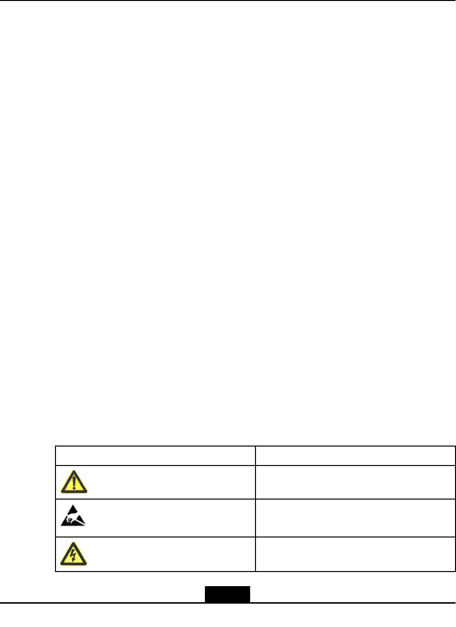
6.1.2SafetySymbols
Table6-1listssafetysymbols.
Table6-1SafetySymbolsDescription
SafetySymbolMeaning
Universalalertingsymbol:Generalsafety
attentions.
Electrostatic:Devicemaybesensitivetostatic
electricity.
Electricshock:Thereisariskofelectricshock.
6-1
SJ-20110329145303-001|2011–10–25(R1.1)ZTEProprietaryandCondential
ZXSDRBS8802C100UserGuide
SafetySymbolMeaning
Hightemperature:Surfaceishotandmaycause
personalinjuryiftouched.
Laser:Bewareofstronglaserbeam.
Microwave:Bewareofstrongelectromagnetic
eld.
Nosmoking:Smokingisforbidden.
NoFlammables:Noammablematerialscan
bestored.
Notouching:Donottouch.
Amongstthesesafetysymbols,theuniversalalarmsymbolsareclassiedintofourlevels:
danger,warning,caution,andnote.Theformatsandmeaningsofthefourlevelsare
describedasbelow:
Danger!
Indicatesanimminentlyhazardoussituation,which,ifnotavoided,couldresultindeathor
seriousinjury.Limititsusetoonlyextremesituations.
Warning!
Indicatesahazardoussituation,which,ifnotavoided,couldresultinseriousinjuries,
equipmentdamagesorinterruptionofmajorservices.
Caution!
Indicatesapotentiallyhazardoussituation,which,ifnotavoided,couldresultinmoderate
injuries,equipmentdamagesorpartialserviceinterruption.
6-2
SJ-20110329145303-001|2011–10–25(R1.1)ZTEProprietaryandCondential
Chapter6HardwareInstallation
Note:
Indicateshelpfulinformationwhichifignored,couldresultinminorinjuries,equipment
damagesorpartialserviceinterruption.
Everysafetysymbolhasatextdescriptionofitssafetylevelandadetaileddescriptionof
itscontents.
6.1.3SafetySpecifications
ElectricalSafety
Danger!
Neverinstalloruninstallpowercableswhiletheyarelivebecausewhentouchedwitha
conductormayproducesparks,resultinginreordamagetoeyes.
Doshutoffpowersupplybeforeconnectingordisconnectingapowercable.
Beforeconnectingacable,makesurethatthecableanditslabelmeettheactual
installationrequirements.
Warning!
Itisnotallowedtodrillcabinetholeswithoutpermission.Unqualieddrillingcoulddamage
wiringinsidethecabinet.Additionally,themetalpiecesinsidethecabinetcreatedbydrilling
couldresultinashortedcircuitboard.
Antistatic
Caution!
Staticelectricityproducedbyhumanbodycandamagestatic-sensitivecomponentson
circuitboard,suchaslarge-scaleintegratedcircuits.
Frictioncausedbyhumanbodyactivitiesistherootcauseofelectrostaticcharge
accumulation.Staticvoltagecarriedbyahumanbodyinadryenvironmentcanbeup
to30kV,andcanremaininthereforalongtime.Anoperatorwithstaticelectricity
6-3
SJ-20110329145303-001|2011–10–25(R1.1)ZTEProprietaryandCondential
ZXSDRBS8802C100UserGuide
maydischargeelectricitythroughacomponentwhenhe/shetouchestheconductorand
causingdamage.
Wearanantistaticwriststrap(theotherendofwriststrapmustbewellgrounded)before
touchingtheequipmentorholdingaplug-inboard,circuitboard,IntegratedCircuit(IC)chip
orotherdevices,topreventhumanstaticelectricityfromdamagingsensitivecomponents.
Laser
Warning!
Avoidlookingstraightatthelaserbeamfromtheoutletoftheopticaltransceiverorinside
theopticalbertoavoideyedamage.
HighTemperature
Danger!
Avoidtouchingthesurfaceareaofsomedevicesduetohightemperaturetoavoidascald
injury.
Fans
Warning!
Donotputngersoranytoolsintherunningfantoavoidaninjury.Keeptoolsawayfrom
therunningfan.
Stickingngerinsidearunningfanmaycausehurt.
Putparts,screws,andtoolsawayfromthefanwhenreplacingrelatedparts,toavoid
damagetothefanorrelateddevices.
Keepngersandboardawayfromthefanwhenreplacingdevicesaroundthefan,toavoid
damagetotheequipmentorngers.
6-4
SJ-20110329145303-001|2011–10–25(R1.1)ZTEProprietaryandCondential
Chapter6HardwareInstallation
HoistingHeavyObjects
Warning!
Donotwalkorstayunderthehoistedobjectsduringhoistingoperations.
lEnsureaproperhoistingcapabilityofthehoisterwhendisassemblingheavy
equipmentmoving,andreplacingequipment.
lTheoperatormustreceivethetrainingandqualicationforhoistingoperations.In-
spectandcompletethehoistingtoolsbeforegettingintoservice.
lMakesuretoxthehoistingtoolsrmlyonasufcientlysecuredobjectorwallbefore
thehoistingoperation.
lUsebrieforalinstructionsduringthehoistingoperationstopreventmistaken
operation.
Plugging/UnpluggingModules
Themodulesmentionedinthisdocumentincludefrontboard,rearboard,andfanmodule.
Caution!
lAvoidinsertingamoduleforcibly.Otherwise,thepinonthebackplanemaybent.
lAlignthemodulewiththeguiderailandpushitgentlytothebackplane.Plugthe
moduleproperlyintotheslottopreventshortcircuitduetocontactbetweenthemodule
andthecircuitsurface.
lAvoidtouchingthecircuits,components,connectors,andcabletroughswhenholding
amodule.
lRFmoduleturnshotwhenrunning.Avoidbeingscaldedwhenpluggingand
unplugginganRFmodule.
Personnel
Caution!
Donotconductinternalmaintenanceorequipmentdebuggingwithoutpriorpermission.
Replacingpartsorchangingequipmentmayincurextradanger,therefore,donotreplace
partsorchangetheequipmentwithoutpriorpermission.T oensuresafety,pleasecontact
ZTEincaseofanyproblem.
6-5
SJ-20110329145303-001|2011–10–25(R1.1)ZTEProprietaryandCondential
ZXSDRBS8802C100UserGuide
6.2InstallationPreparation
Beforetheinstallation,checktheenvironmentandensurethatrelatedinstallationtools,
instruments,anddocumentationareavailable.
1.Tool,instrument,anddocumentation
Tool
Adjustablewrenches,inner-hexagonspanner,straightscrewdriver,cross
screwdriver,pliers(sharp-nosepliers,diagonalpliers,andvices),tapemeasure,
antistaticwriststrap,andelectricpercussiondrill
InstrumentGradienter,goniometer,andmultimeter
Documenta-
tion
ZXSDRBS8802C100UserGuide
2.Environmentcheck
Environmentrequirement
Indoorinstallation
Workingtemperature:–20℃~+45℃
Relativehumidity:5%~95%
PowerrequirementLocalpowersupply:85VACto264VAC
FacilityrequirementVerticalwall,levelceiling,verticalpole
6.3ChassisInstallation
ZXSDRBS8802C100iscompactinstructureandoccupiessmallfootprint.Therefore,
itcanbeexiblyinstalledinvariousindoorplaces.Inactualapplication,themost
commonlyusedinstallationmodesarewall-mountedinstallation,poleinstallation,and
ceilinginstallation.
6.3.1Pole-MountingaZXSDRBS8802C100
Context
ThediameterofthepoleusedtoinstallaZXSDRBS8802C100mustrangefrom20mm
to110mm.
Prerequisites
TheoperatorisresponsibleforprovidingandinstallingpoleswhileZTEcorporation
suppliesrelevantcomponentsandpartsforpole-mountedinstallationonly.
6-6
SJ-20110329145303-001|2011–10–25(R1.1)ZTEProprietaryandCondential
Chapter6HardwareInstallation
Steps
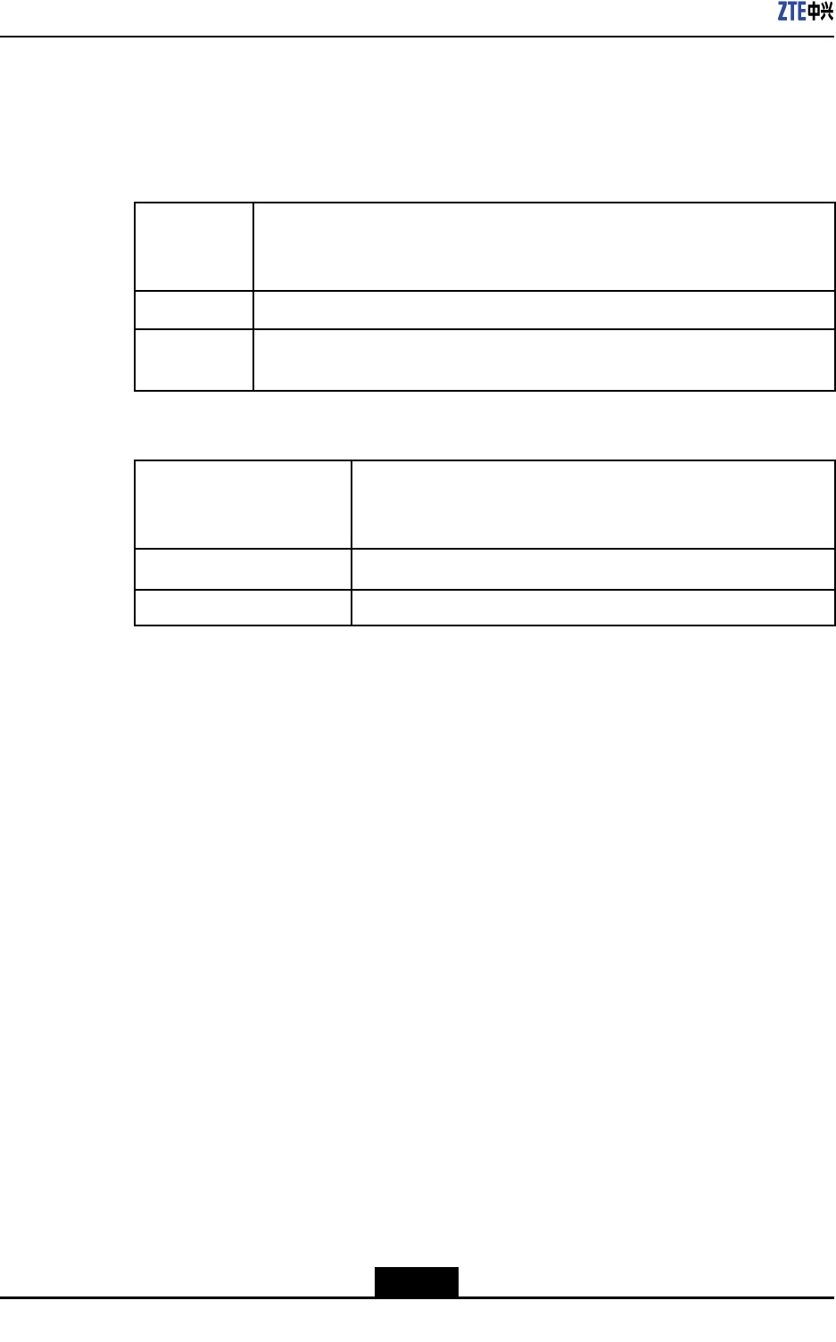
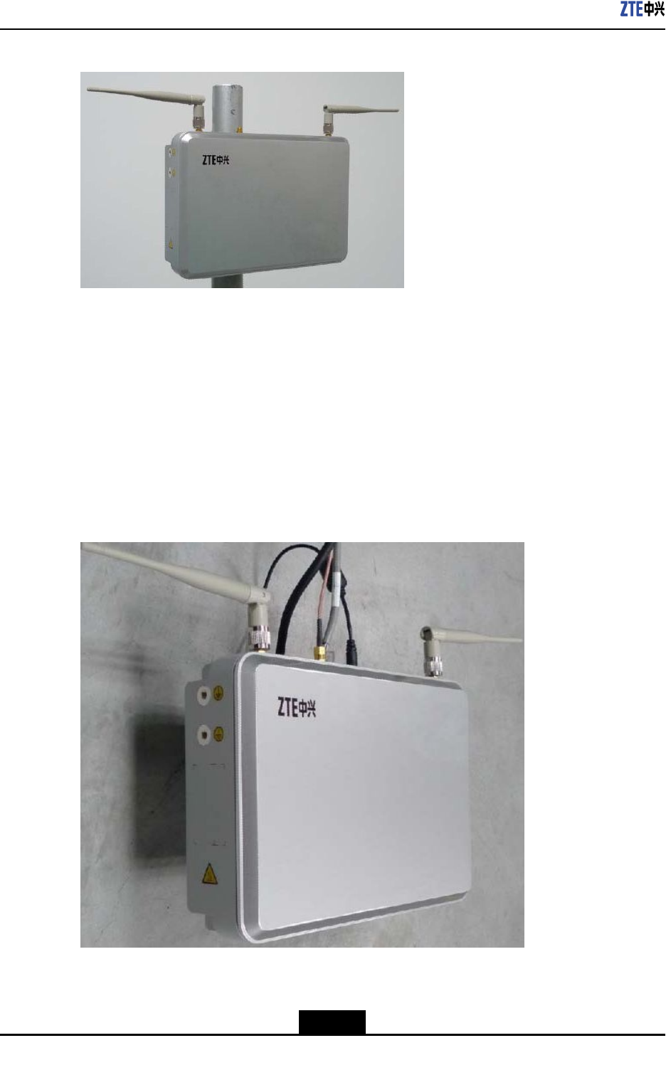
1.MakesurethattheUPonthepoweradapterbracketoftheZXSDRBS8802C100
facesupward.Bindthepoweradapterbracketontothepolewithtwobarclamps,as
showninFigure6-1.
Figure6-1FixingthePowerAdapterBracketontothePole
1.Barclasp2.Poweradapterbracket
2.MakesurethattheUPontheinstallingbracketfacesupward.Inserttheinstalling
bracketintothepoweradapterbracket.
3.Fixtheinstallingbracketontothepoweradapterbracketwithscrews,asshown
inFigure6-2.
6-7
SJ-20110329145303-001|2011–10–25(R1.1)ZTEProprietaryandCondential
ZXSDRBS8802C100UserGuide
Figure6-5Pole-MountedInstallation
6.3.2Wall-MountedInstallation
6.3.2.1Wall-MountinganOverlappedZXSDRBS8802C100andPowerAdapter
Context
Ifnosufcientroomisavailable,thepoweradapterbracketandtheinstallingbracketcan
overlaptosaveroom,asshowninFigure6-6.
Figure6-6OverlappedFixingBrackets
6-10
SJ-20110329145303-001|2011–10–25(R1.1)ZTEProprietaryandCondential
Chapter6HardwareInstallation
Steps
1.PutthepoweradapterbracketoftheZXSDRBS8802C100onthewallandmarkthe
installationholesaccordingtothesizeofthepoweradapterbracket.
2.UseapercussivedrilltodrillΦ6X40mmholesinthemarkedinstallationpositions,and
inserttheexpansionboltsdeliveredwiththeZXSDRBS8802C100intotheholes.
3.Fixthepoweradapterbracketonthewallwithxingscrewsaccordingtothepositions
oftheinstallationholes.
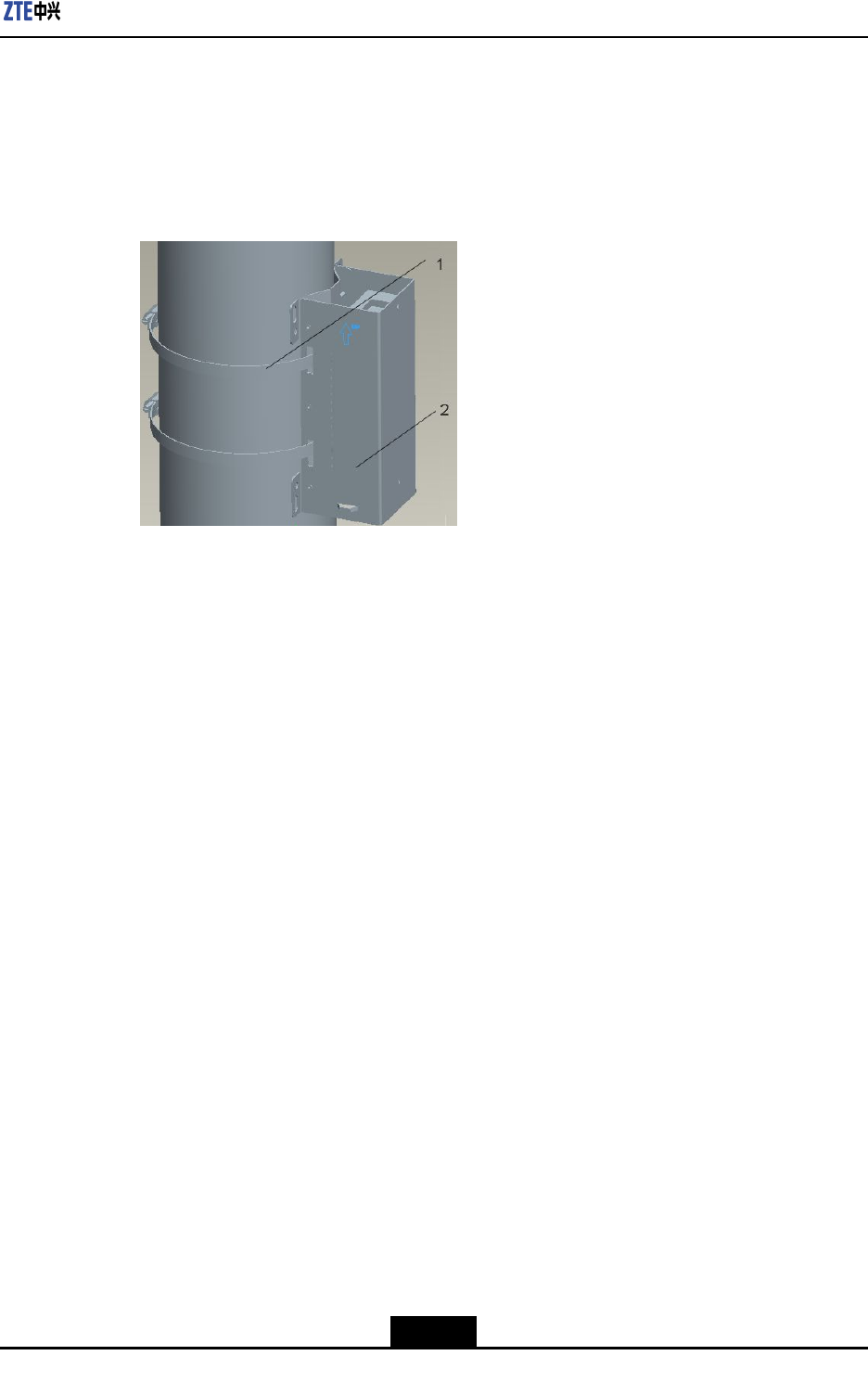
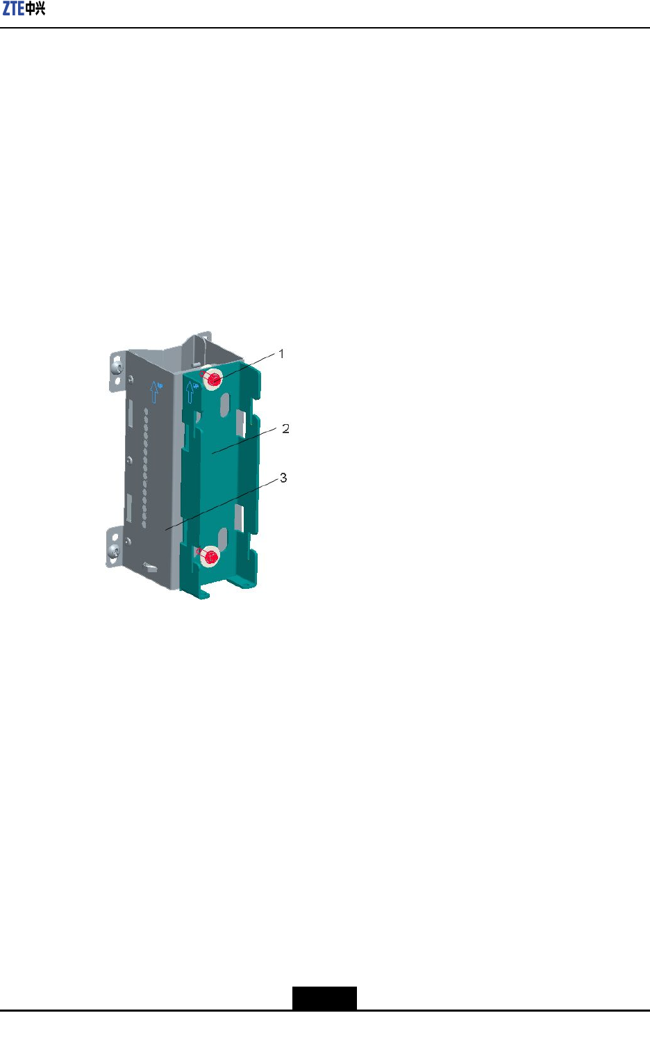
4.MakesurethattheUPontheinstallingbracketfacesupward,andinserttheinstalling
bracketintothepoweradapterbracket,andusetwoscrewstoxtheinstallingbracket,
asshowninFigure6-7.
Figure6-7InsertingtheInstallingBracket
1.Fixingscrews2.Installingbracket3.Poweradapterbracket
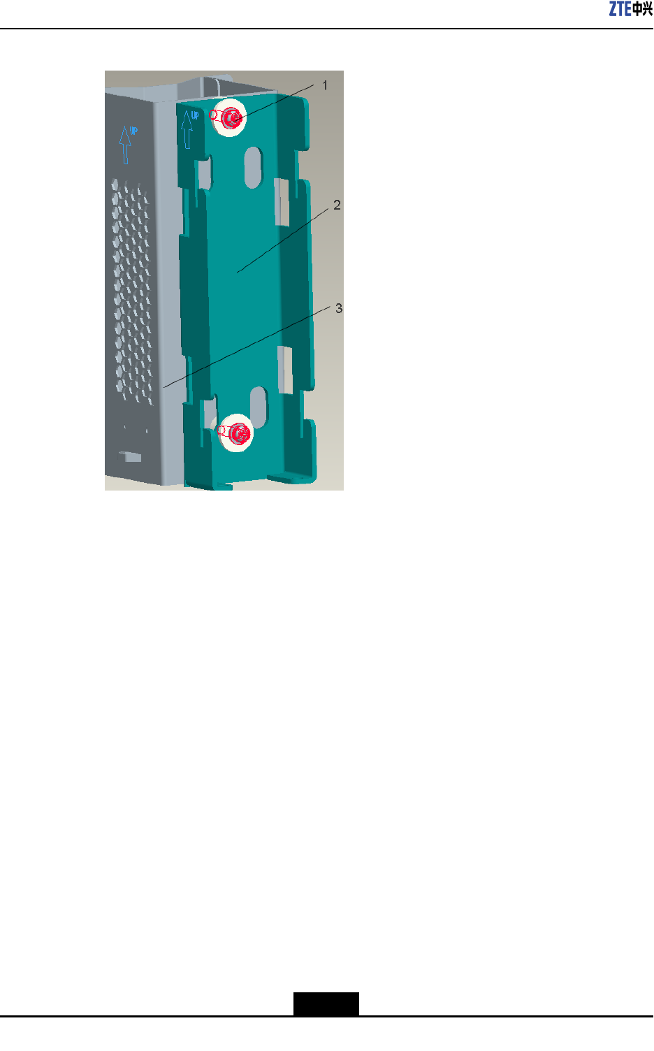
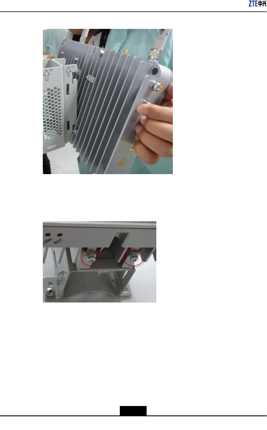
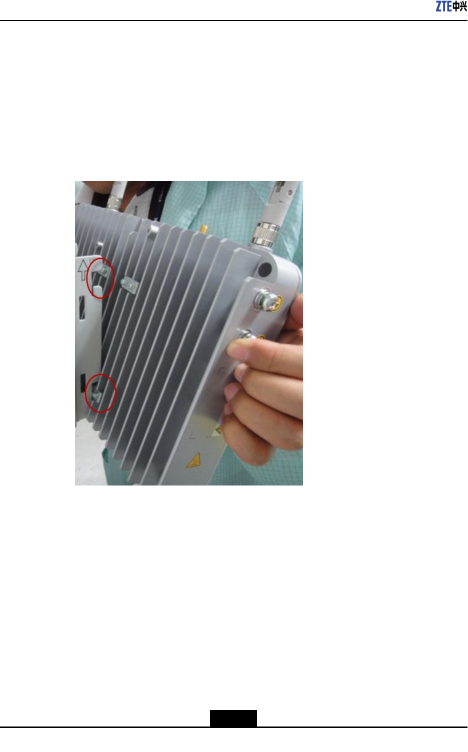
5.InsertthefourhooksatthebackoftheZXSDRBS8802C100intothefourslotsofthe
installingbracket,asshowninFigure6-8.
6-11
SJ-20110329145303-001|2011–10–25(R1.1)ZTEProprietaryandCondential
ZXSDRBS8802C100UserGuide
Figure6-8HangingtheZXSDRBS8802C100
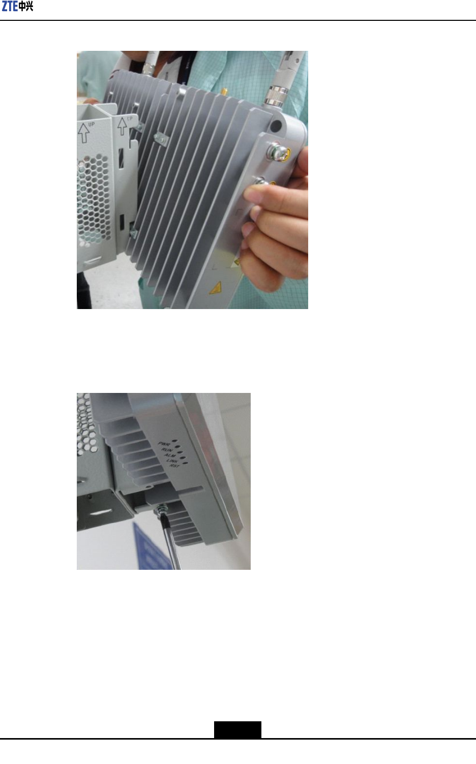
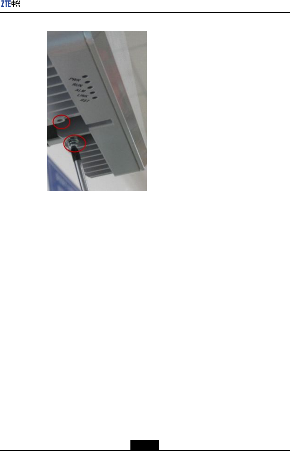
6.UsetwoscrewstoxtheZXSDRBS8802C100,asshowninFigure6-9.
Figure6-9FixingtheZXSDRBS8802C100
–EndofSteps–
6.3.2.2SeparatelyWall-MountingtheZXSDRBS8802C100andPowerAdapter
Context
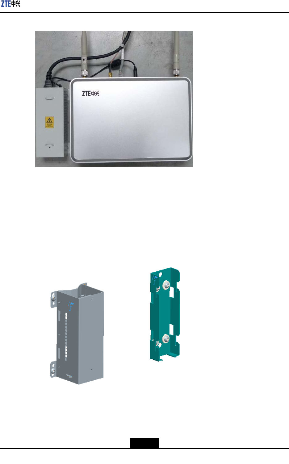
Ifsufcientroomisavailable,installthepoweradapterbracketandtheinstallingbracket
separatelyforbetterheatdissipation,asshowninFigure6-10.
6-12
SJ-20110329145303-001|2011–10–25(R1.1)ZTEProprietaryandCondential
Chapter6HardwareInstallation
Figure6-10SeparatelyWall-MountedZXSDRBS8802C100andPowerAdapter
Steps
1.Putthepoweradapterbracketonthewallandmarktheinstallationpositionsaccording
tothesizeofthepoweradapterbracket.
2.Puttheinstallingbracket150mmto180mmawayfromthepoweradapterbracketat
thesamehorizonofthewall,andmarktheinstallationpositionsaccordingtothesize
oftheinstallingbracket,asshowninFigure6-11.
Figure6-11DecidingtheInstallationPositionsoftheInstallingBracket
3.UseapercussivedrilltodrillΦ6X40mmholesaccordingtothemarkedinstallation
positions,andinserttheexpansionboltsdeliveredwiththeZXSDRBS8802C100into
theholes.
6-13
SJ-20110329145303-001|2011–10–25(R1.1)ZTEProprietaryandCondential
ZXSDRBS8802C100UserGuide
4.Fixthepoweradapterbracketonthewallwithxingscrewsaccordingtoitsinstallation
positions.
5.Fixtheinstallingbracketonthewallwithxingscrewsaccordingtoitsinstallation
positions.
6.EmbedthefourhooksatthebackoftheZXSDRBS8802C100intothefourslotsof
theinstallingbracket,asshowninFigure6-12.
Figure6-12HangingtheZXSDRBS8802C100
7.UsetwoscrewstoxtheZXSDRBS8802C100,asshowninFigure6-13.
6-14
SJ-20110329145303-001|2011–10–25(R1.1)ZTEProprietaryandCondential
Chapter6HardwareInstallation
Figure6-13FixingtheZXSDRBS8802C100
–EndofSteps–
6.3.3Ceiling-MountingtheZXSDRBS8802C100
Context
Inviewoftheendurableweight,thecementceilingischosenforceilinginstallation.
Figure6-14showstheceilinginstallationmode.
6-15
SJ-20110329145303-001|2011–10–25(R1.1)ZTEProprietaryandCondential
ZXSDRBS8802C100UserGuide
Figure6-14CeilingInstallation
Steps
1.Conrmtheinstallationpositionandputtheauxiliaryinstallingpartontotheceiling.
Markthepositionsoftheinstallationholesontheceilingaccordingtothesizeofthe
auxiliaryinstallingpart,asshowninFigure6-15.
Figure6-15MarkingInstallationHolePositionsoftheAuxiliaryInstallingPart
2.RemovetheauxiliaryinstallingpartanduseapercussivedrilltodrillthreeΦ6X40mm
holes.TheninstalltheexpansionboltsdeliveredwiththeZXSDRBS8802C100into
theholes.
6-16
SJ-20110329145303-001|2011–10–25(R1.1)ZTEProprietaryandCondential
Chapter6HardwareInstallation
3.Installtheauxiliaryinstallingpartaccordingtotheholepositionsandxitontothe
ceilingwithxingscrews.
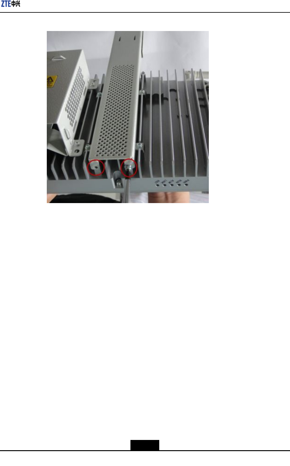
4.Fixtheceiling-mountedbracketontotheauxiliaryinstallingpartwiththreescrews,as
showninFigure6-16.
Figure6-16Ceil-MountingtheBracket
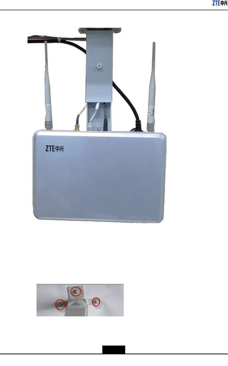
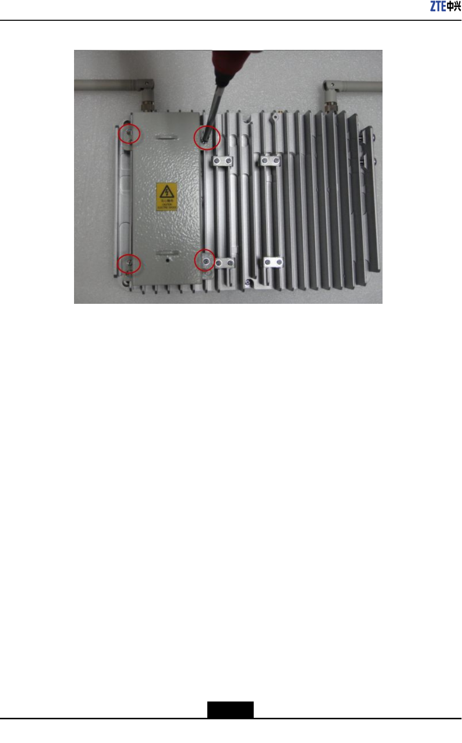
5.UsefourscrewstoxthepoweradapterbracketatthebackoftheZXSDRBS8802
C100,asshowninFigure6-17.
6-17
SJ-20110329145303-001|2011–10–25(R1.1)ZTEProprietaryandCondential
Chapter6HardwareInstallation
Figure6-18FixingtheZXSDRBS8802C100
–EndofSteps–
6.4CableInstallation
AfterinstallingtheZXSDRBS8802C100chassis,connectthecables.Thecablestobe
connectedareasfollows:
lEthernetcable
lPowercable
lGPScable
6.5GPSAntennaFeederSystemInstallation
6.5.1GPSAntennaInstallation
6.5.1.1InstallingaGPSAntennainVerticalPlacement
Prerequisites
Thefollowingtoolsmustbeready.
lAdjustablespanner
lNormalSpanner
6-19
SJ-20110329145303-001|2011–10–25(R1.1)ZTEProprietaryandCondential
ZXSDRBS8802C100UserGuide
Itisrecommendedtohaveapolewithadiameterbetween30mm~60mm(48mmis
recommended).Theantennashouldnotbeinstalledduringrainandheavywind.Thepole
bindingwithGPSantennaconnectedtoGNDisrequired.
Steps
1.OpenthepackageandtakeouttheGPSantennaandGPSrack.
2.UsetheU-shapedclamptoinstalltheGPSracktothemountingpole.Insertaspring
washerandwasherbetweentheU-shapedclampandmountingpole.
3.UseaM6nuttoxtheU-shapedclampandthepoletogetherrmly.
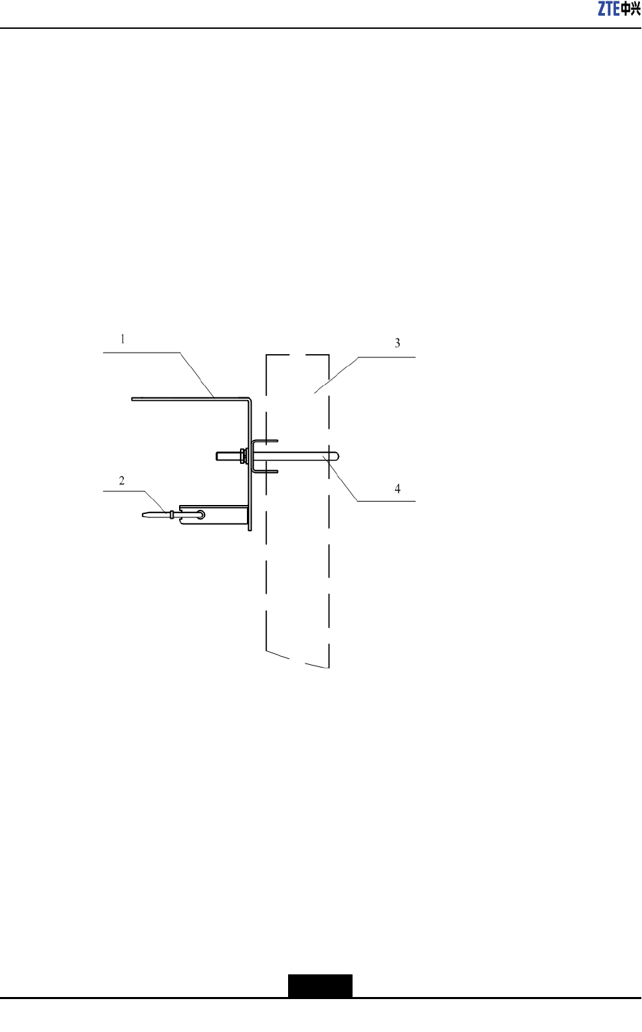
Figure6-19showsthexingprocess.
Figure6-19U-shapedClampInstallation
1.GPSsettledclamp
2.Cablestrip
3.Mountingpole
4.U-shapedclamp
4.FixtheGPSantennatotheGPSsettledclamp.Screwthebolt(M4x14)tormlyx
theantenna.
–EndofSteps–
Result
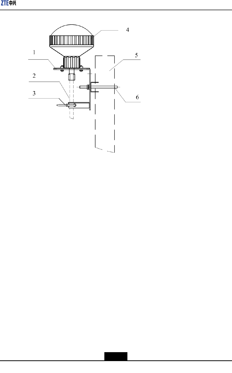
Figure6-20showstheantennaxedintheverticalposition.
6-20
SJ-20110329145303-001|2011–10–25(R1.1)ZTEProprietaryandCondential
Chapter6HardwareInstallation
Figure6-20GPSAntennaVerticalInstallation
1.GPSsettledclamp
2.Feeder
3.Feederstrip
4.GPSantenna
5.Mountingpole
6.U-shapeclamp
6.5.1.2InstallingaGPSAntennainHorizontalPlacement
Prerequisites
ConrmtheinstallationmodeandinstallationpositionofGPSantenna.
Thefollowingtoolsmustbeready.
lAdjustablespanner
lNormalspanner
Context
lItisrecommendedtohaveapolewithadiameterbetween30mm~60mm(48mm
isoptimal).
lThepoleusedtoxtheGPSantennamustbegroundedwell.
lTheantennacannotbeinstalledduringrainandheavywind.
Steps
1.OpenthepackageandtakeouttheGPSantennaandGPSrack.
2.UsetheU-shapeclamptoinstalltheGPSracktothemountingpole.
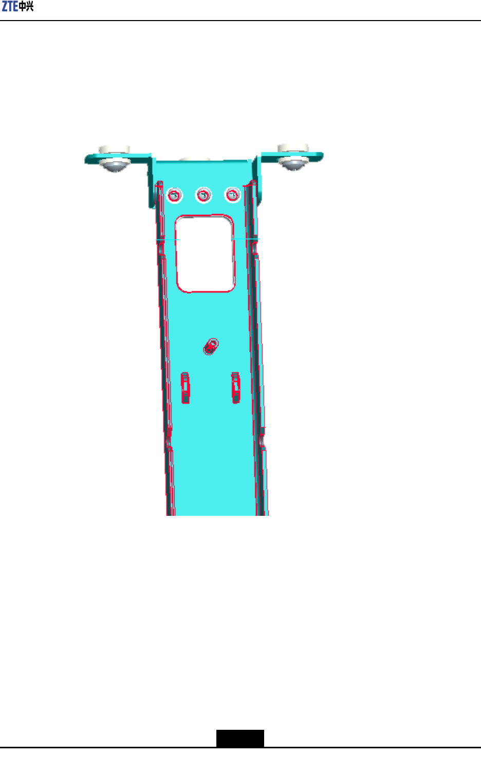
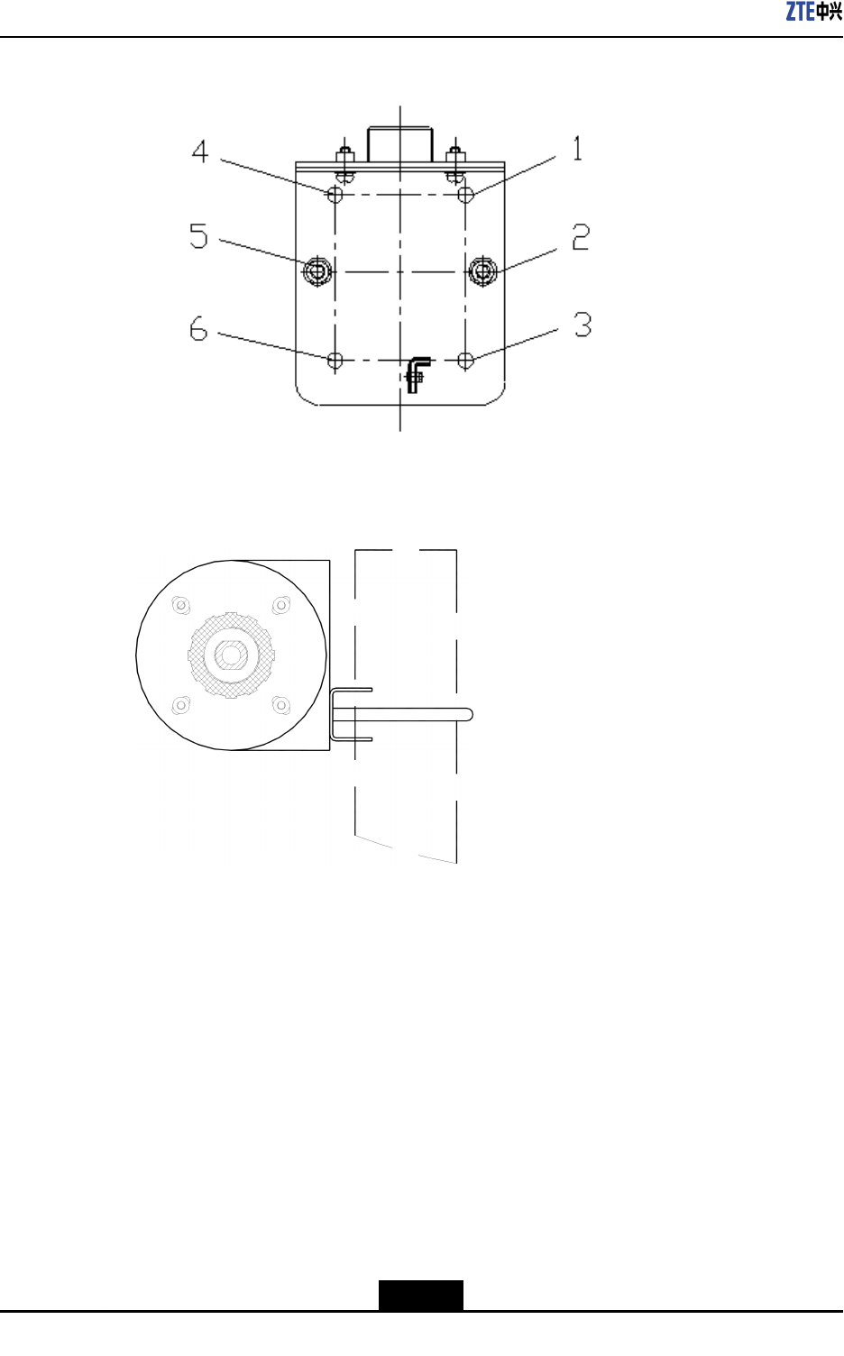
3.TheinstallationsupportofGPSantennaisasshowninFigure6-21.Alignholeson
theU-shapeclampwithHole1andHole3,orHole4andHole6ontheinstallation
support.Thencoveraspringwashandatwasherrespectivelyontheseholesand
fastenthemwithM6screws,asshowninFigure6-22.
6-21
SJ-20110329145303-001|2011–10–25(R1.1)ZTEProprietaryandCondential
ZXSDRBS8802C100UserGuide
Figure6-21GPSAntennaRackInstallationSupport
•1~6holeposition
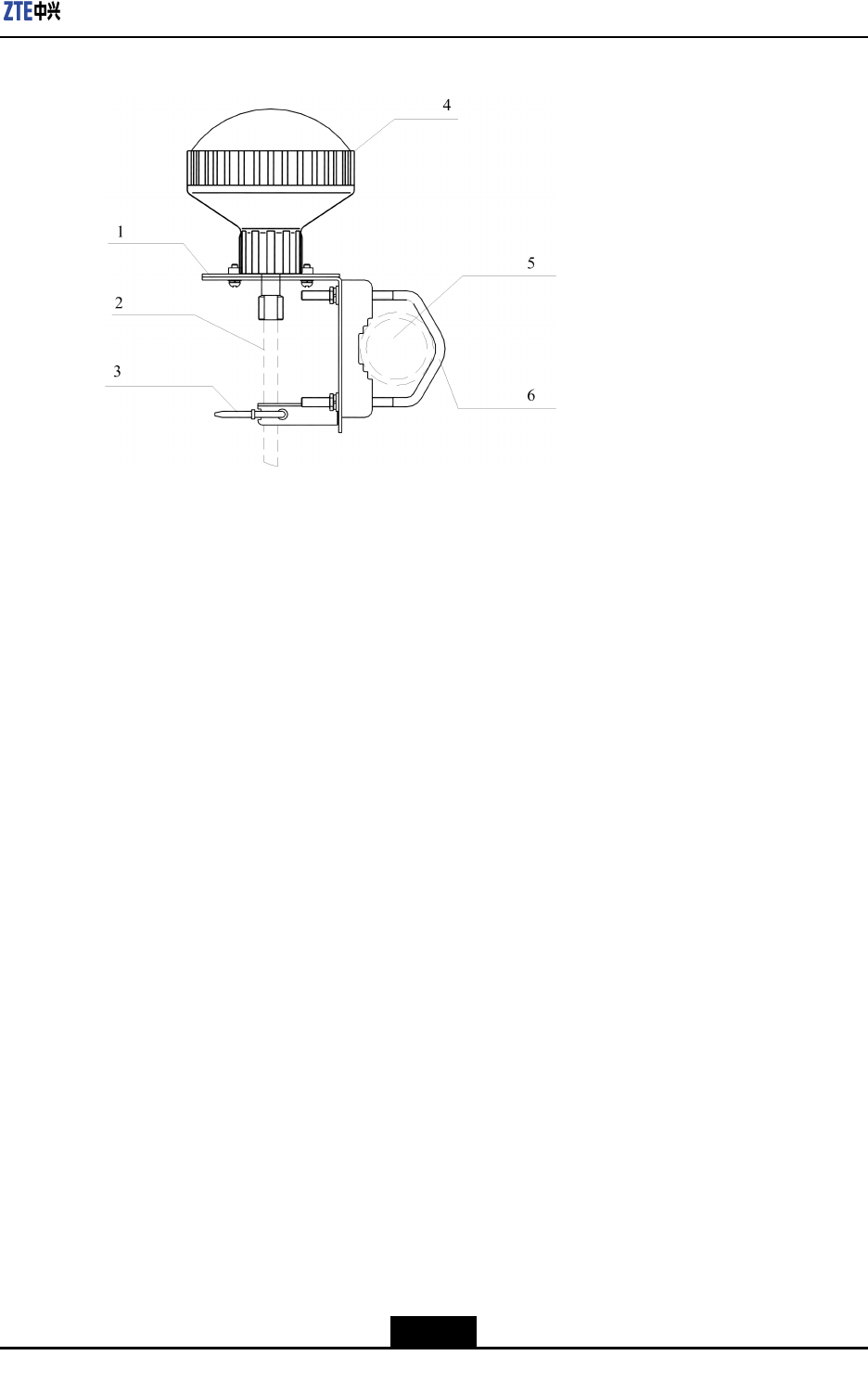
Figure6-22GPSRackInstallation(HorizontalPlacement)
4.FixtheGPSantennatotheGPSsettledclamp.Screwdownthebolt(M4x14)tormly
xtheantenna.
–EndofSteps–
Result
Figure6-23showstheGPSantennaxedhorizontally.
6-22
SJ-20110329145303-001|2011–10–25(R1.1)ZTEProprietaryandCondential
Chapter6HardwareInstallation
Figure6-23GPSAntennaFixedHorizontally
1.GPSsettledclamp
2.Feeder
3.Feederstrip
4.GPSantenna
5.Mountingpole
6.U-shapeclamp
6.5.1.3Wall-MountingaGPSAntenna
Prerequisites
Thefollowingtoolsmustbeready.
lAdjustablespanner
lNormalspanner
lHammer
lExpansionanchorbolts(M5x30orM5x40)
Context
ForinstallingtheGPSAntennaonthewall,theU-shapeclampisunnecessary.
Steps
1.OpenthepackageandtakeouttheGPSantennaandGPSrack.
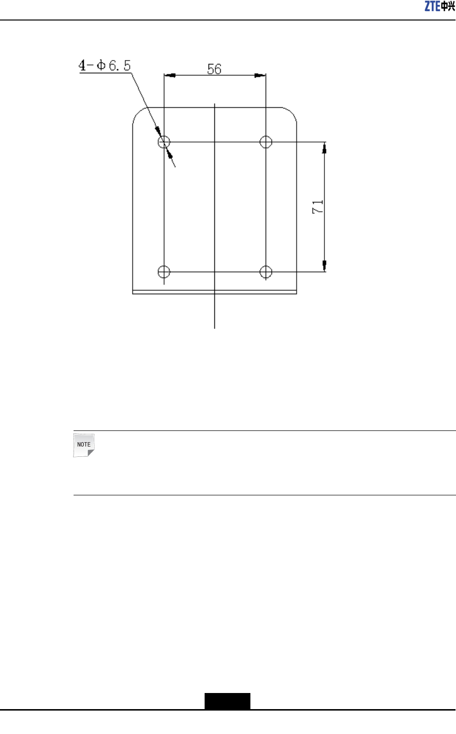
2.Usethedesigntemplateformarkingholesonthewall.Thendrillholesonthewall
accordingtothesizeoftheexpansionanchorboltsthataretobeused.
Figure6-24showsthedesigntemplate.
6-23
SJ-20110329145303-001|2011–10–25(R1.1)ZTEProprietaryandCondential
ZXSDRBS8802C100UserGuide
Figure6-24DesignTemplateforMarkingHoles
3.Inserttheexpansionbolts,andhammerthemtoxproperly.
4.InstalltheGPSantennaracktothecorrespondingboltposition.
5.InsertaspringwasherandatwasherontoexpansionboltsandusetheM6nuttox
therackonthewallrmly.
Note:
Thetorqueusedtoxtheclampis45Nm.
6.FixtheGPSantennatotheGPSsettledclampandscrewtheM4x14bolttightly.
–EndofSteps–
Result
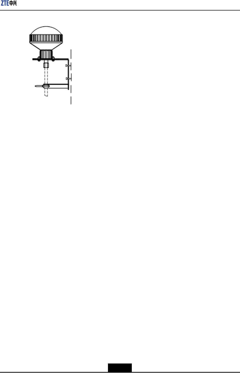
Figure6-25showstheGPSantennaxedonthewall.
6-24
SJ-20110329145303-001|2011–10–25(R1.1)ZTEProprietaryandCondential
Chapter6HardwareInstallation
Figure6-25GPSAntennaFixedonWall
6.5.2GPSFeederCableSelectionPrinciple
TheselectionofGPSfeedercableshouldbemadebasedonthefollowing4conditions:
1.Ifthefeederlength≤80m,thenselectan1/4″feedercable.
2.If80mthefeederlength≤150m,thenselectan1/2″feedercable.
3.If150mthefeederlength≤300m,thenselectan1/2"feedercable+7/8"feeder
cable+1/2"feedercable.
4.Ifthefeederlengthismorethan300m,contactthelocalrepresentativeofceofZTE
Corporation.
6-25
SJ-20110329145303-001|2011–10–25(R1.1)ZTEProprietaryandCondential

ZXSDRBS8802C100UserGuide
Thispageintentionallyleftblank.
6-26
SJ-20110329145303-001|2011–10–25(R1.1)ZTEProprietaryandCondential

Figures
Figure1-1PositionofZXSDRBS8802C100inCDMAsystem.................................1-2
Figure1-2ZXSDRBS8802C100Appearance..........................................................1-3
Figure1-3ExternalInterfaces...................................................................................1-6
Figure2-1ZXSDRBS8802C100SystemStructure..................................................2-1
Figure2-2PRAStructure..........................................................................................2-2
Figure4-1ExistingTransmissionResource..............................................................4-1
Figure4-2MobileDataNetwork................................................................................4-2
Figure4-3PublicNetworkResource.........................................................................4-2
Figure5-1IndoorCoverage......................................................................................5-1
Figure5-2FamilyCoverage......................................................................................5-2
Figure5-3EnterpriseSolution..................................................................................5-2
Figure5-4HotSpotandBlindAreaCoverage..........................................................5-3
Figure6-1FixingthePowerAdapterBracketontothePole......................................6-7
Figure6-2FixingtheInstallingBracket.....................................................................6-8
Figure6-3HangingtheZXSDRBS8802C100..........................................................6-9
Figure6-4FixingtheZXSDRBS8802C100.............................................................6-9
Figure6-5Pole-MountedInstallation.......................................................................6-10
Figure6-6OverlappedFixingBrackets...................................................................6-10
Figure6-7InsertingtheInstallingBracket...............................................................6-11
Figure6-8HangingtheZXSDRBS8802C100........................................................6-12
Figure6-9FixingtheZXSDRBS8802C100...........................................................6-12
Figure6-10SeparatelyWall-MountedZXSDRBS8802C100andPowerAdapter
.............................................................................................................6-13
Figure6-11DecidingtheInstallationPositionsoftheInstallingBracket...................6-13
Figure6-12HangingtheZXSDRBS8802C100......................................................6-14
Figure6-13FixingtheZXSDRBS8802C100.........................................................6-15
Figure6-14CeilingInstallation................................................................................6-16
Figure6-15MarkingInstallationHolePositionsoftheAuxiliaryInstalling
Part.......................................................................................................6-16
Figure6-16Ceil-MountingtheBracket....................................................................6-17
Figure6-17FixingthePowerAdapterBracket........................................................6-18
Figure6-18FixingtheZXSDRBS8802C100.........................................................6-19
I

ZXSDRBS8802C100UserGuide
Figure6-19U-shapedClampInstallation................................................................6-20
Figure6-20GPSAntennaVerticalInstallation.........................................................6-21
Figure6-21GPSAntennaRackInstallationSupport...............................................6-22
Figure6-22GPSRackInstallation(HorizontalPlacement).....................................6-22
Figure6-23GPSAntennaFixedHorizontally..........................................................6-23
Figure6-24DesignTemplateforMarkingHoles......................................................6-24
Figure6-25GPSAntennaFixedonWall.................................................................6-25
II

Tables
Table1-1ZXSDRBS8802C100Functions...............................................................1-4
Table1-2ExternalInterfaces....................................................................................1-7
Table2-1ZXSDRBS8802C100ModulesandTheirFunctions.................................2-2
Table3-1ZXSDRBS8802C100CapacityIndices....................................................3-1
Table3-2800MHzTransmitterIndices.....................................................................3-2
Table3-31.9GHzTransmitterIndices......................................................................3-4
Table3-4800MHzReceiverIndices.........................................................................3-5
Table3-51.9GHzReceiverIndices..........................................................................3-6
Table6-1SafetySymbolsDescription.......................................................................6-1
III

Tables
Thispageintentionallyleftblank.

Glossary
BSC
-BaseStationController
BSS
-BaseStationSystem
BTS
-BaseTransceiverStation
CDMA
-CodeDivisionMultipleAccess
GPS
-GlobalPositioningSystem
MSS
-MobileSwitchingSystem
V