ZTE C806 CDMA Remote Radio Unit-8860 User Manual
ZTE Corporation CDMA Remote Radio Unit-8860 Users Manual
ZTE >
Users Manual

ZXSDRR8860
CDMARemoteRadioUnit-8860
TechnicalManual
ZTECORPORATION
NO.55,Hi-techRoadSouth,ShenZhen,P .R.China
Postcode:518057
Tel:+86-755-26771900
Fax:+86-755-26770801
URL:http://ensupport.zte.com.cn
E-mail:support@zte.com.cn

LEGALINFORMATION
Copyright©2011ZTECORPORATION.
Thecontentsofthisdocumentareprotectedbycopyrightlawsandinternationaltreaties.Anyreproductionor
distributionofthisdocumentoranyportionofthisdocument,inanyformbyanymeans,withoutthepriorwritten
consentofZTECORPORATIONisprohibited.Additionally,thecontentsofthisdocumentareprotectedby
contractualcondentialityobligations.
Allcompany,brandandproductnamesaretradeorservicemarks,orregisteredtradeorservicemarks,ofZTE
CORPORATIONoroftheirrespectiveowners.
Thisdocumentisprovided“asis”,andallexpress,implied,orstatutorywarranties,representationsorconditions
aredisclaimed,includingwithoutlimitationanyimpliedwarrantyofmerchantability,tnessforaparticularpurpose,
titleornon-infringement.ZTECORPORATIONanditslicensorsshallnotbeliablefordamagesresultingfromthe
useoforrelianceontheinformationcontainedherein.
ZTECORPORATIONoritslicensorsmayhavecurrentorpendingintellectualpropertyrightsorapplications
coveringthesubjectmatterofthisdocument.ExceptasexpresslyprovidedinanywrittenlicensebetweenZTE
CORPORATIONanditslicensee,theuserofthisdocumentshallnotacquireanylicensetothesubjectmatter
herein.
ZTECORPORATIONreservestherighttoupgradeormaketechnicalchangetothisproductwithoutfurthernotice.
UsersmayvisitZTEtechnicalsupportwebsitehttp://ensupport.zte.com.cntoinquirerelatedinformation.
TheultimaterighttointerpretthisproductresidesinZTECORPORATION.
RevisionHistory
RevisionNo.RevisionDateRevisionReason
R1.008/30/2010FirstEdition
SerialNumber:SJ-20100722143906-001
PublishingDate:08/30/2010

DeclarationofRoHS
Compliance
Tominimizetheenvironmentalimpactandtakemoreresponsibilitytotheearthwelive,
thisdocumentshallserveasformaldeclarationthatZXSDRR8860manufacturedby
ZTECORPORATIONareincompliancewiththeDirective2002/95/ECoftheEuropean
Parliament-RoHS(RestrictionofHazardousSubstances)withrespecttothefollowing
substances:
lLead(Pb)
lMercury(Hg)
lCadmium(Cd)
lHexavalentChromium(Cr(VI))
lPolyBrominatedBiphenyls(PBB’s)
lPolyBrominatedDiphenylEthers(PBDE’s)
…
TheZXSDRR8860manufacturedbyZTECORPORATIONmeettherequirementsofEU2002/95/EC;
however,someassembliesarecustomizedtoclientspecications.Additionofspecialized,
customer-speciedmaterialsorprocesseswhichdonotmeettherequirementsofEU2002/95/EC
maynegateRoHScomplianceoftheassembly.T oguaranteecomplianceoftheassembly,the
needforcompliantproductmustbecommunicatedtoZTECORPORATIONinwrittenform.This
declarationisissuedbasedonourcurrentlevelofknowledge.Sinceconditionsofuseareoutside
ourcontrol,ZTECORPORATIONmakesnowarranties,expressorimplied,andassumesnoliability
inconnectionwiththeuseofthisinformation.
I

II

FCC&ICSTATEMENT
Thisdevicecomplieswithpart15oftheFCCRules.Operationissubjecttothefollowing
twoconditions:
1.Thisdevicemaynotcauseharmfulinterference.
2.Thisdevicemustacceptanyinterferencereceived,includinginterferencethatmay
causeundesiredoperation.
ThisClass[A]digitalapparatuscomplieswithCanadianICES-003.
Note:
Workingwiththeequipmentwhileinoperation,mayexposethetechniciantoRF
electromagneticeldsthatexceedFCCrulesforhumanexposure.VisittheFCC
websiteatwww.fcc.gov/oet/rfsafetytolearnmoreabouttheeffectsofexposuretoRF
electromagneticelds.
Changesormodicationstothisunitnotexpresslyapprovedbythepartyresponsiblefor
compliancewillvoidtheuser’sauthoritytooperatetheequipment.Anychangetothe
equipmentwillvoidFCCandICgrant.
ThisequipmenthasbeentestedandfoundtocomplywiththelimitsforaClassAdigital
device,pursuanttotheFCCandICRules.Thisequipmentgenerates,usesandcan
radiateradiofrequencyenergyand,ifnotinstalledandusedinaccordancewiththe
instructions,maycauseharmfulinterferencetoradiocommunications.However,thereis
noguaranteethatinterferencewillnotoccurinaparticularinstallation.
I

II

RFExposureInformationfor
PMR
TheproductgeneratesRFelectromagneticenergyduringtransmitmode.
Thisradioisdesignedforandclassiedas“OccupationalUseOnly”,meaningitmust
beusedonlyduringthecourseofemploymentbyindividualsawareofthehazards,and
thewaystominimizesuchhazards.ThisradioisNOTintendedforusebythe“General
Population”inanuncontrolledenvironment.
ThisradiohasbeentestedandcomplieswiththeFCCRFexposurelimitsfor“Occupational
UseOnly”.
Inaddition,theproductcomplieswiththefollowingStandardsandGuidelineswithregard
toRFenergyandelectromagneticenergylevelsandevaluationofsuchlevelsforexposure
tohumans:
1.FCCOETBulletin65Edition97-01SupplementC,EvaluatingCompliancewithFCC
GuidelinesforHumanExposuretoRadioFrequencyElectromagneticFields.
2.tAmericanNationalStandardsInstitute(C95.1-1992),IEEEStandardforSafetyLevels
withRespecttoHumanExposuretoRadioFrequencyElectromagneticFields,3kHz
to300GHz.
3.AmericanNationalStandardsInstitute(C95.3-1992),IEEERecommendedPractice
fortheMeasurementofPotentiallyHazardousElectromagneticFields–RFand
Microwave.
4.Thefollowingaccessoriesareauthorizedforusewiththisproduct.Useofaccessories
otherthanthose(listedintheinstruction)speciedmayresultinRFexposurelevels
exceedingtheFCCrequirementsforwirelessRFexposure.
I

II

AboutThisManual
Purpose
ZXSDRR8860isanoutdoorremoteRFunit.ComposinganintegratedBTS,ZXSDR
R8860andZXSDRR8860implementwirelesstransmissionwithincoverageareas,control
ofwirelesschannelaswellascommunicationwithBSC.
ThismanualprovidesZXSDRR8860productoverview,whichwillhelpthereaders
knowtheproduct’sfunction,principle,specication,features,cabinet,modules,external
interfacesandcables.
IntendedAudience
Thisdocumentisintendedforengineersandtechnicianswhoperformoperationactivities
ZXSDRR8860.
lEngineeringtechnicians
lEquipmentinstallationengineers
lEquipmentcommissioningengineers
PrerequisiteSkillandKnowledge
Tousethisdocumenteffectively,usersshouldhaveageneralunderstandingofZXSDR
R8860equipmentanditscomponents.Familiaritywiththefollowingishelpful:
lZXSDRR8860hardwarestructure
lBasicsoftwareknowledge
WhatisinThisManual
Thismanualcontainsthefollowingchapters.
ChapterSummary
Chapter1Product
Overview
Thischapterdescribesproduct’sfunction,specication,featuresandtechnical
specications.
Chapter2
Hardware
Description
Thischapterdescribesproduct’smodulefunctionandworkprinciple,cables’s
structureandmainantennasystem.
Chapter3
ProtocolInterface
Description
Thischapterdescribesproduct’sprotocolinterfaces.
Conventions
ZTEdocumentsemploythefollowingtypographicalconventions.
I

TypefaceMeaning
ItalicsReferencestootherManualsanddocuments.
“Quotes”Linksonscreens.
BoldMenus,menuoptions,functionnames,inputelds,radiobuttonnames,check
boxes,drop-downlists,dialogboxnames,windownames.
CAPSKeysonthekeyboardandbuttonsonscreensandcompanyname.
Note:Providesadditionalinformationaboutacertaintopic.
Checkpoint:Indicatesthataparticularstepneedstobecheckedbefore
proceedingfurther.
Tip:Indicatesasuggestionorhinttomakethingseasierormoreproductive
forthereader.
Mouseoperationconventionsarelistedasfollows:
TypefaceMeaning
ClickReferstoclickingtheprimarymousebutton(usuallytheleftmousebutton)once.
Double-clickReferstoquicklyclickingtheprimarymousebutton(usuallytheleftmousebutton)
twice.
Right-clickReferstoclickingthesecondarymousebutton(usuallytherightmousebutton)
once.
II

Contents
DeclarationofRoHSCompliance.................................................................I
FCC&ICSTATEMENT...................................................................................I
RFExposureInformationforPMR................................................................I
AboutThisManual.........................................................................................I
Chapter1ProductOverview.....................................................................1-1
1.1DistributedZTEBTSSolution..............................................................................1-1
1.2PositionintheNetwork.......................................................................................1-2
1.3Appearance.......................................................................................................1-3
1.4Functions...........................................................................................................1-4
1.5Features............................................................................................................1-5
1.6ExternalInterfaces.............................................................................................1-6
1.7ApplicationScenarios.........................................................................................1-7
1.8WorkPrinciple..................................................................................................1-10
1.8.1SystemStructure....................................................................................1-10
1.8.2SignalFlow............................................................................................1-10
1.9Networking.......................................................................................................1-11
1.9.1Baseband-RFInterfaceNetworking..........................................................1-11
1.9.2CascadeNetworking..............................................................................1-12
1.9.3FrequencyExtensionNetworking............................................................1-12
1.10EquipmentManagementModes......................................................................1-13
1.10.1OMCMode..........................................................................................1-13
1.10.2LMTMode...........................................................................................1-14
1.11T echnicalIndices............................................................................................1-15
1.11.1EngineeringIndices..............................................................................1-15
1.11.2PerformanceIndices.............................................................................1-16
1.11.3RFIndicies...........................................................................................1-17
1.12ComplianceStandards....................................................................................1-18
Chapter2HardwareDescriptions.............................................................2-1
2.1Cabinet..............................................................................................................2-1
2.1.1ExternalStructure....................................................................................2-1
2.1.2IndoorStructure.......................................................................................2-2
2.1.3VentilationandHeat-dissipationPrinciples.................................................2-3
2.2Modules.............................................................................................................2-3
I

2.2.1ModulesList............................................................................................2-3
2.2.2FilterLNA(FL).........................................................................................2-3
2.2.3Transceiver(TR)......................................................................................2-4
2.2.4PowerAmplier(PA)................................................................................2-5
2.2.5Power......................................................................................................2-5
2.3ExternalCables..................................................................................................2-5
2.3.1DCPowerCable......................................................................................2-5
2.3.2GroundingCable......................................................................................2-6
2.3.3AISGControlCable..................................................................................2-6
2.3.4OpticalFiberCable...................................................................................2-7
2.3.5EnvironmentMonitoringCable..................................................................2-7
2.3.6CarrierSectorExtensionCable.................................................................2-8
2.3.7RFJumperCable.....................................................................................2-9
2.4MainAntennaFeederSystem...........................................................................2-10
2.4.1MainAntennaFeederSystemStructure...................................................2-10
2.4.2Antenna.................................................................................................2-14
2.4.3FeederStructure....................................................................................2-15
Chapter3ProtocolInterfaceDescription.................................................3-1
3.1NetworkReferenceModel...................................................................................3-1
3.2UmInterface......................................................................................................3-2
3.3Baseband—RFInterface....................................................................................3-6
Figures.............................................................................................................I
Tables............................................................................................................III
Glossary.........................................................................................................V
II
Chapter1
ProductOverview
TableofContents
DistributedZTEBTSSolution.....................................................................................1-1
PositionintheNetwork...............................................................................................1-2
Appearance................................................................................................................1-3
Functions...................................................................................................................1-4
Features.....................................................................................................................1-5
ExternalInterfaces.....................................................................................................1-6
ApplicationScenarios.................................................................................................1-7
WorkPrinciple..........................................................................................................1-10
Networking...............................................................................................................1-11
EquipmentManagementModes...............................................................................1-13
TechnicalIndices......................................................................................................1-15
ComplianceStandards.............................................................................................1-18
1.1DistributedZTEBTSSolution
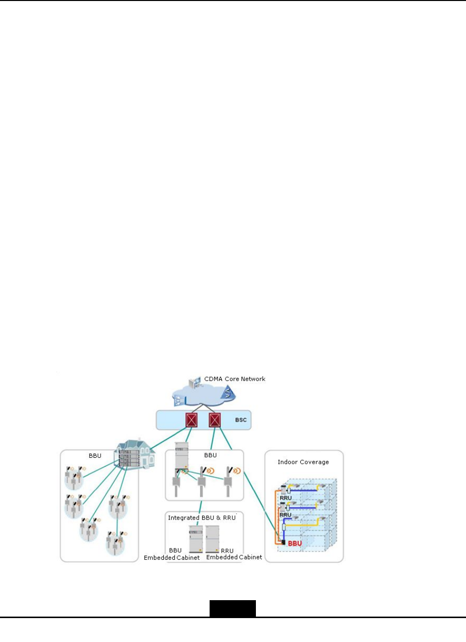
Inordertoprovidemorecompetitivecommunicationdevicesandsolutionsforcustomers,
ZTEprovidesdistributedZTECDMA2000BBU+RRUsolutiontoaccomplishservice
functionsofCDMA2000BTSs.
Figure1-1showsthearchitectureofdistributedZTEBTSsolution.
Figure1-1DistributedZTEBTSSolution
1-1
SJ-20100722143906-001|08/30/2010ZTEProprietaryandCondential

ZXSDRR8860TechnicalManual
ThedistributedBTSsolutionofZTECDMA2000BBU+RRUhasthefollowingadvantages:
lLowlaborandengineeringexpenses.
Itssmallsizeandlightnessfacilitatestransportationandengineeringinstallation.
lLowroomrentandquicknetworkestablishment.
Itisapplicabletovariousscenarios.Itcanbeinstalledonatower,abuildingtopor
awall.Theexibleadaptabilityfacilitatesquicknetworkdeploymentandsavesroom
rentsandnetworkoperationexpenses,takingadvantageofTime-T o-Market.
lConvenientupgradingandexpansion.
Itsupportsmultiplecarriersectors.Thenumberofcabinetsvarieswiththeactual
situation.
lDecreaseinthetotalnumberofsites.
TheRRUcanbeinstalledasclosetotheantennaaspossible,whichsavesfeeder
expenses,reducesfeederloss,improvesRRUon-topoutputpowerandincreasesthe
coverage.
lLowpowerconsumption.
ComparedwithtraditionalBTSs,thedistributedBBU+RRUBTShaslowerpower
consumption,whichreducespowerinvestment,saveselectricalexpensesand
networkoperationcost.
lDistributednetworkingmode.
ItsupportsstarandchainnetworkingbetweenBBUsandRRUs,effectivelymaking
fulluseofnetworkresources.
lAdvanceduniversalBTSplatform.
TheBBUusesaB3Gand4Gorientedplatformthatimplementsvariousstandards
sothatasingleBTScansupportmultiplestandards.Thishelpsoperatorsintegrate
multipleBTSsintoamulti-modeBTS,simplifyingthemanagementofBTSssothat
operatorscanexiblychoosenetworkevolutiondirectionsanduserscanenjoythe
transparenceandsmoothevolutionofnetworks.
1.2PositionintheNetwork
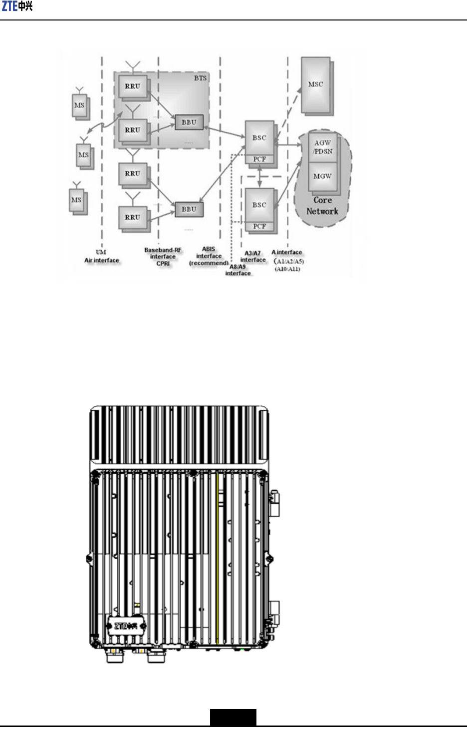
ZXSDRR8860isanoutdoorremoteRadioFrequency(RF)unitofZTECDMA2000series.
ZXSDRR8860,togetherwiththeBBU,constitutesanintegratedBaseTransceiverStation
(BTS).ZXSDRR8860implementswirelesstransmissioninitscoveragearea.Figure1-2
showsthepositionofZXSDRR8860(RRU)intheCDMAnetwork.
1-2
SJ-20100722143906-001|08/30/2010ZTEProprietaryandCondential

ZXSDRR8860TechnicalManual
1.4Functions
Table1-1describesZXSDRR8860functions.
Table1-1ZXSDRR8860Functions
FunctionDescription
Band:
800MHzBandClass0
1900MHzPCS
450MHz(BandClass5)
850MHz(BandClass10)
420MHz(BandClass5)
2100MHz(BandClass6)
AWSBandClass15
RFmodulation/demodulation
RFtransceiverduplexer
LownoiseamplicationforreceivedRFsignal
AmplicationfortransmittedRFsignal
RF
RFtransceiver
Baseband-RFinterface:compliantwithCommonPublicRadio
Interface(CPRI)protocol
Airinterface:compliantwithIS-2000ReleaseAandIS-856-A
Interface
Localdebuggingandmaintenanceinterface:Ethernet
SupportfortheremoteapplicationoftheRRU;networking
modesareinvolvedintostarandchain.
CombinedRFcabinets(diversityoutput/input) Networking
SupportforthecascadingnetworkingmodeofRRU,thehighest
upto4levels
Inputpowerundervoltage/overvoltagealarm
Outputpowerundervoltage/overvoltagealarm
Powerovercurrentalarm
Environmenttemperaturealarm
ExternalRS-485monitoringinterface
EnvironmentMonitoring
Externalmonitoringextensioninterface:4inputdrycontacts
1-4
SJ-20100722143906-001|08/30/2010ZTEProprietaryandCondential
Chapter1ProductOverview
FunctionDescription
Electroniclabel
Powerquery:basebandpower,RFpower,andantennaoutput
power
Automaticcalibration
RSSIquery
Reversespectrumquery:queryingthereversereceivedsignal
spectrumofeachcarrier
monitoringalarmforantennastandingwaveratio
Equipmentmaintenanceand
testing
Poweramplicationcontrolandprotection:over-power,
over-temperature,andstandingwavealarm.
1.5Features
ThefeaturesoftheZXSDRR8860areasfollows:
lSmallSize
TheZXSDRR8860occupiesasmallarea,savingroomrentexpenses.
àDimensionofasingleZXSDRR8860cabinetwithouthandle(HxWxD):500
mm×320mm×172mm.Wheninstalledindoors,itrequiresasmallinstallation
area.
àZXSDRR8860canalsobeinstalledoutdoors,supportingpole-mount,
wall-mount,andGantrymountinstallations.ExceptfortheGantrymount
installation,whichoccupiesminimumoorspace,theothercasesalmostdoes
notoccupyanyoorspace.
lLightWeight
AsingleZXSDRR8860cabinetweighs22kgsoitiseasytotransportandinstall,
requiringlowmanpowerandengineeringcosts.
lOpticalberSupport
ZXSDRR8860supportsopticalberinstallationonatower.ZXSDRR8860andthe
BBUcanbeconnectedviabers.Onepairofberscansupportalargenumberof
sectorswhichgreatlylowersantennafeedercostandengineeringexpenses
lLowPowerConsumption
Lowerpowerconsumptionimposeslowerpowersupplyrequirements,savingpower
constructioncostsanddailypowercharges.
àPowerconsumption:(<350W,-48VDC)
àLessRFpowerlossbecausetheinstallationofZXSDRR8860onthetowerclose
toantennasrequiresashorterfeedercable.
1-5
SJ-20100722143906-001|08/30/2010ZTEProprietaryandCondential
ZXSDRR8860TechnicalManual
àHigherpoweramplicationefciency(>30%,-48VDC).
lNaturalDissipation
Noheatexchangerisneededwhenthecabinetisinstalledoutdoors.
lAtmost8carriersx80WRFpower.
supportsvariousapplicationscenariosincludingdenseurbancoverageandwiderural
areacoverage.Itprovidesdiversityreceptionfunctionandsupportstransmission
diversityand4-antennareceptionbymeansofcabinetcombination.
lComplexNetworkApplication
supportsbaseband-RFstarandchainnetworks,deliveringexiblesolutionsto
complicatednetworkenvironments.
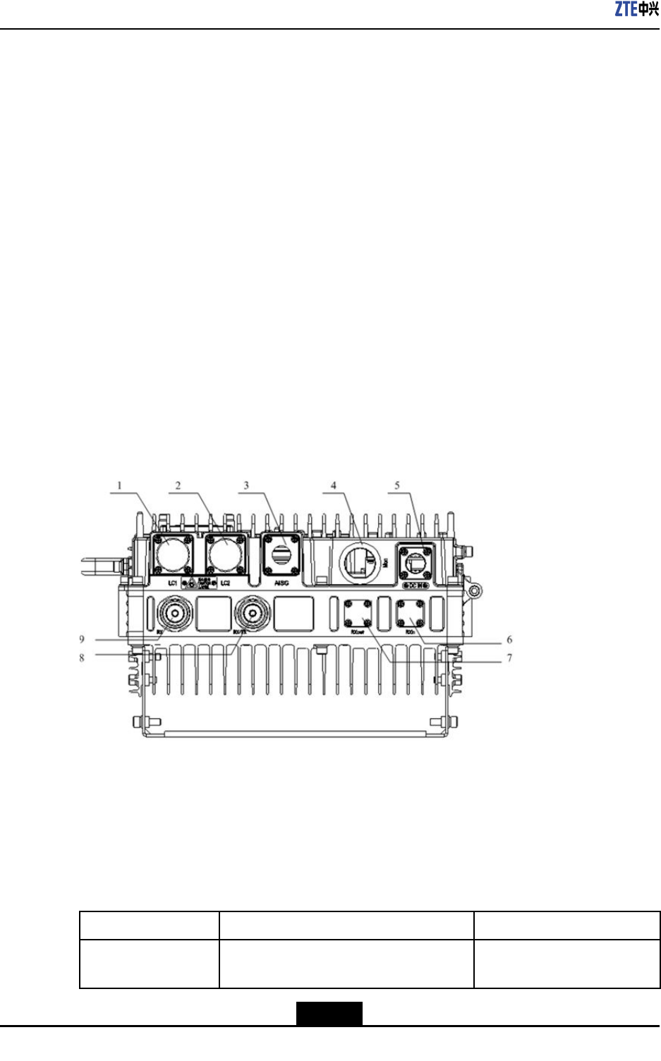
1.6ExternalInterfaces
TheexternalinterfacessupportedbytheZXSDRR8860arelocatedatthebottomofthe
cabinet.
Figure1-4showstheexternalinterfacesofZXSDRR8860.
Figure1-4ZXSDRR8860ExternalInterfaces
1.LC1
2.LC2
3.AISG
4.Mon
5.DCIN
6.RXIn
7.RXout
8.RX/TX
9.RX
InterfaceDescription
Table1-2liststheZXSDRR8860interfacesdescription.
Table1-2ZXSDRR8860ExternalInterfacesDescription
InterfaceNameFunctionInterfaceType/Connector
LC1InterfacebetweenBBUandRRU/RRU
cascadinginterface
LCopticalinterface
1-6
SJ-20100722143906-001|08/30/2010ZTEProprietaryandCondential

Chapter1ProductOverview
InterfaceNameFunctionInterfaceType/Connector
LC2InterfacebetweenBBUandRRU/RRU
cascadinginterface
LCopticalinterface
AISGAISGdeviceinterface8-coreaerialsocket
MonExternaldeviceinterface37-coreaerialsocket
DCINPowerinterfaceDCinterfaceconnector:4-pin
straightroundconnector
RXInFrequencyexpansioninterfaceNconnector
RXoutFrequencyexpansioninterfaceNconnector
RX/TXReceive/TransmitmainsetRFcable
interface
50ΩDINconnector
RXReceivediversityRFcableinterface50ΩDINconnector
1.7ApplicationScenarios
ZXSDRR8860supportsgantry-mount,wall-mount,pole-mountandsimplied—cabinet
integrativeinstallationmodes.
Theapplicationscenariosareclassiedintothefollowingsituationsaccordingtodifferent
installationconditions,powersupplyrequirementsanduserdemands:
lIntheconditionofZXSDRR8860indoorinstallationwiththeDCpowercable10
moutsidetheequipmentroomandwithoutLevelBandabovelightningmodule
conguredintheindoorpoweroutput,theindoorDClightningboxisadoptedfor
powersupplyandpowerdistribution.
lWhenZXSDRR8860isinstalledoutdoors,anexternalDClightningboxisadopted
forpowersupplyandpowerdistribution.
lAwavetrapmoduleisneededinsomecountriesordistrictsduetothespecialdemand
ontheradionetworkorstations.
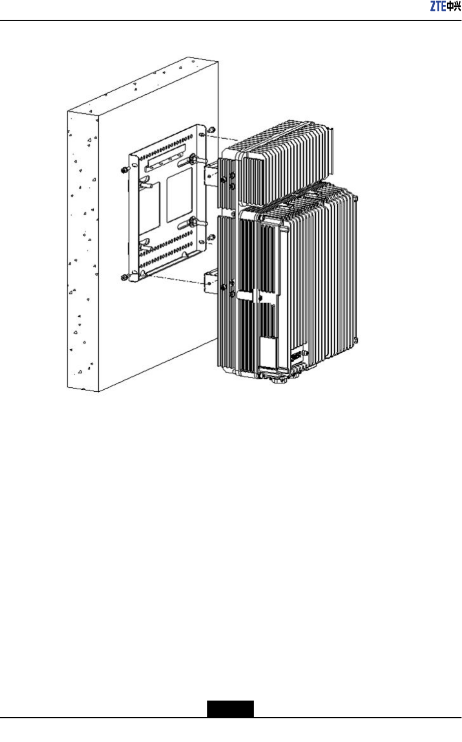
Wall-MountInstallation
Figure1-5illustratesthewall-mountinstallation
1-7
SJ-20100722143906-001|08/30/2010ZTEProprietaryandCondential
ZXSDRR8860TechnicalManual
Figure1-5ZXSDRR8860Wall-MountMode
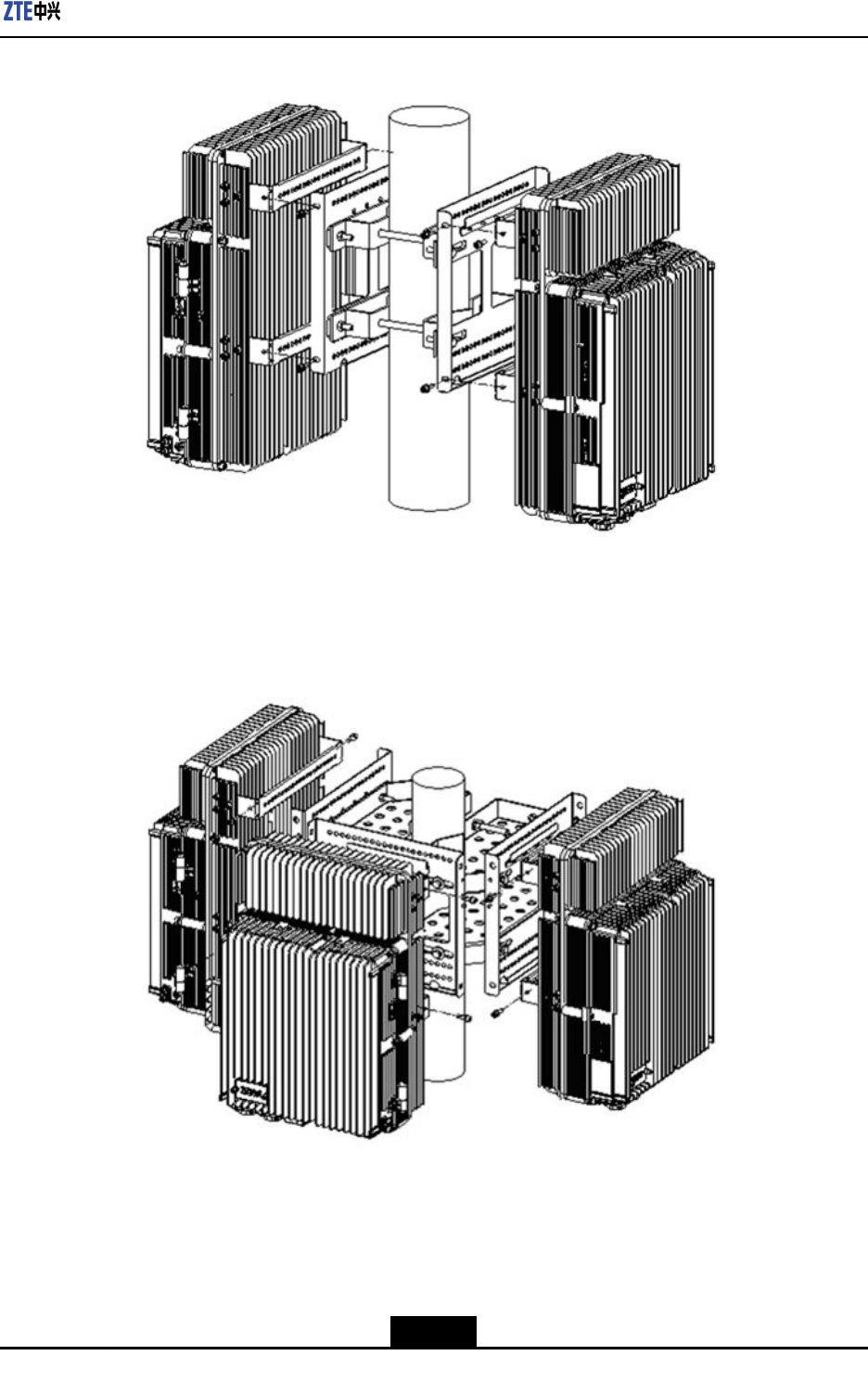
Pole-MountInstallation
ThissectionillustratestheZXSDRR8860pole-mountinstallationintermsofdoubleand
threecabinetsinstallation.
lTwoZXSDRR8860cabinets
Figure1-6illustratestwoZXSDRR8860cabinetsmountedonapole.
1-8
SJ-20100722143906-001|08/30/2010ZTEProprietaryandCondential
ZXSDRR8860TechnicalManual
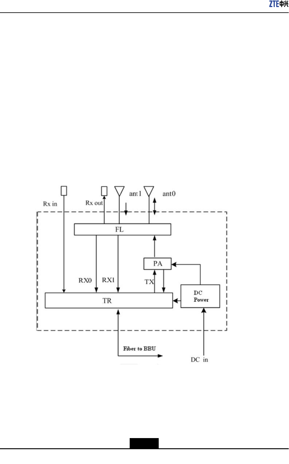
1.8WorkPrinciple
1.8.1SystemStructure
TheZXSDRR8860systemstructureincludesaDCPower(Powersourcemodule),FL
(FilterLNAmodule),TR(Transceivermodule,)andPA(PowerAmpliermodule).Ithas
followingtworeservedports:
lTheZXSDRR8860providesanexternalport(Rxout)tosupportthemutualmain
set/diversitycombinationmode.TheFLmainsetreceptionLowNoiseAmplier(LNA)
outputportdeliversthepowerdivisionfunction.
lAnelectronicswitchissetatthereceivediversitychannelandanexternalinputport
isreservedtodeliverthecompatibilitywiththelong-distancefrequency.Thesystem
canswitchovertoinputsignalsthroughtheFLoflocalRadioUnit(RU)orthrough
anotherRemoteRadioUnit(RRU).
Figure1-8showstheoverallsystemstructure.
Figure1-8ZXSDRR8860SystemStructure
1.8.2SignalFlow
TheZXSDRR8860signalowisdescribedbelow.
ForwardFlow
Theforwardsignalowconsistsoffollowing.
1-10
SJ-20100722143906-001|08/30/2010ZTEProprietaryandCondential
Chapter1ProductOverview
1.AfterreceivingthedatamodulatedbythebasebandunitthroughtheCommonPublic
RadioInterface(CPRI)interface,theupconversionisdonebytheTRandthenthe
signalissenttoPowerAmplier(PA).
2.ThePAampliesthepowerofsignalsandthensendsittothe(DuplexFilter)DFL.
3.TheFLduplexesandlterstheRFsignalsandthentransmitsitthroughtheantenna.
ReverseFlow
Thereversesignalowconsistsofthefollowing.
1.TheFLltersthebackwardCDMAsignalsfromtheantenna,ampliesthepowerof
thesesignalsbeforesendingthemtotheTR.
2.TheTRperformsdownconversionandconvertsthesignalintobasebanddigital
signalsandthentransmitstothebasebandunitthroughtheCPRIinterface.
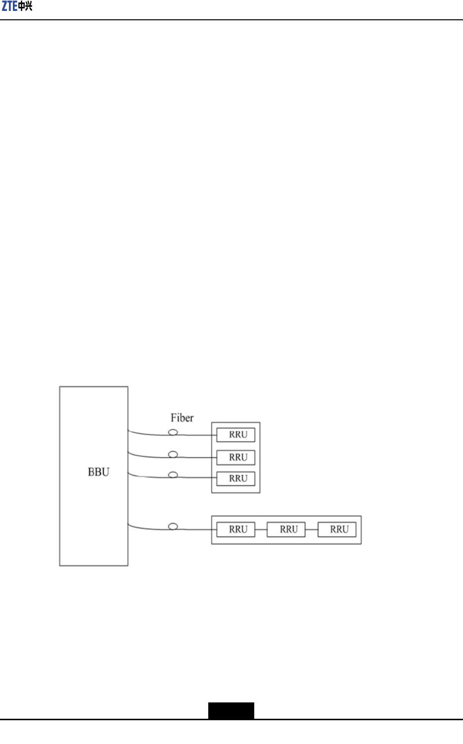
1.9Networking
1.9.1Baseband-RFInterfaceNetworking
TheZXSDRR8860isconnectedtotheBaseBandUnit(BBU)byopticalinterfaces.
ItsupportstheCommonPublicRadioInterface(CPRI)protocol,andstarandchain
networkingmodes,asshowninFigure1-9.
Figure1-9ZXSDRR8860Baseband-RFInterfaceNetworking
lStarnetworking:thenetworkingmodeadoptspoint-to-pointconnection,sothe
numberofbersledoutofthebasebandunitisthesameasthetotalnumberofRF
modules.Althoughmanybersareneeded,thenetworkingmodeismorereliable
thanthechainnetworking.
lChainnetworking:thenetworkingmoderequiresfewerbersbuthaslowerreliability.
1-11
SJ-20100722143906-001|08/30/2010ZTEProprietaryandCondential
ZXSDRR8860TechnicalManual
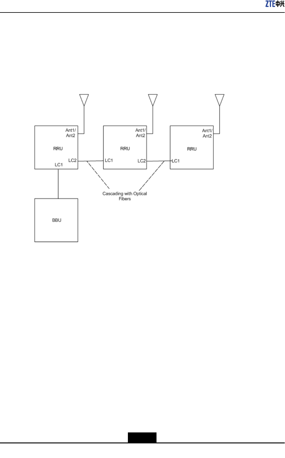
1.9.2CascadeNetworking
InthecasewhereRRUsareclosetoeachotherbutarefarawayfromBBU,thecascade
networkingthroughCPRIinterfaceisrecommendedtosaveopticalbers.
Alternatively,acascadenetworkingisalsotypeofchainnetworking.
Figure1-10showsthecascadenetworkingthroughCPRIinterface.
Figure1-10ZXSDRR8860CascadeNetworking
RRUsareconnectedbyopticalber.TheRRUopticalinterfaceLC1servestoconnect
BBUortheupperlevelRRUwhileLC2servestoconnectthelowerlevelRRU.
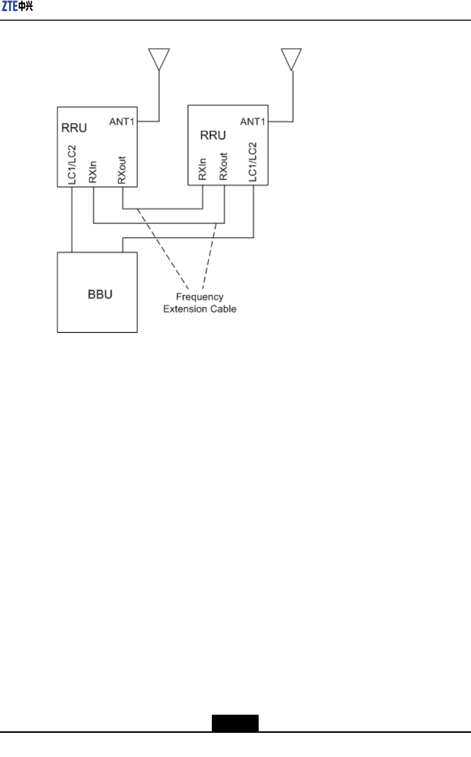
1.9.3FrequencyExtensionNetworking
ZXSDRR8860supportsmutualreceivediversitybymeansofcabinetcombinationsothat
itcansupporthigh-carrierorgreat-carrier-frequency-differenceapplication.
Figure1-11showsthefrequencyextensionnetworkingmodesupportedbyZXSDRR8860.
1-12
SJ-20100722143906-001|08/30/2010ZTEProprietaryandCondential
ZXSDRR8860TechnicalManual
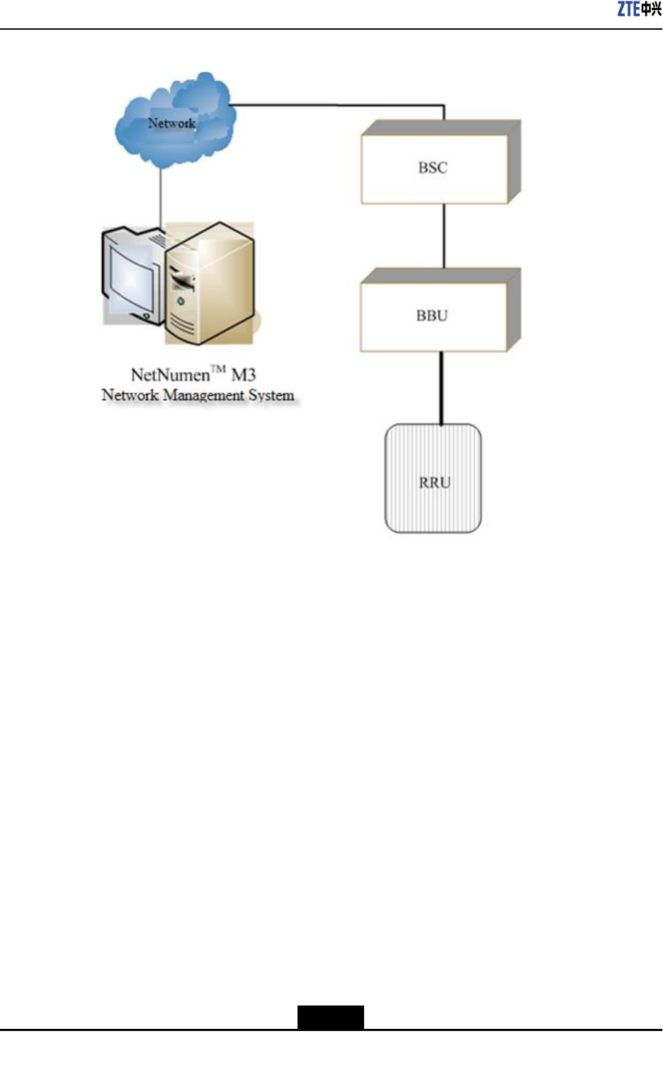
Figure1-12ZXSDRR8860OperationandMaintenance–OMCMode
TheNetworkElement(NE)communicateswiththeNMSthroughtheTCP/IPprotocol.
TheNetNumen™M3providesthefollowingfunctions:
lCongurationManagement
lPerformanceManagement
lFaultManagement
lSecurityManagement
lReportManagement
lSystemTools
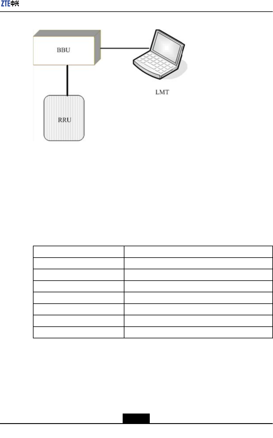
1.10.2LMTMode
ALocalMaintenanceT erminal(LMT)canbeusedtooperateandmaintaintheZXSDR
R8860,asshowninFigure1-13.
1-14
SJ-20100722143906-001|08/30/2010ZTEProprietaryandCondential
Chapter1ProductOverview
Figure1-13ZXSDRR8860OperationandMaintenanceSystem(LMTMode)
Implementationofpowerquery,powerincrease/decreaseorscalingofZXSDRR8860can
beperformedthroughtheLMT.
1.11TechnicalIndices
1.11.1EngineeringIndices
Table1-3describestheengineeringindicesofZXSDRR8860.
Table1-3ZXSDRR8860EngineeringIndices
ItemIndices
OverallDimensionWidthxHeightxDepth:320mmx500mmx172mm
UpperEnclosureDimensionWidthxHeightxDepth:320mmx370mmx72mm
LowerEnclosureDimensionWidthxHeightxDepth:320mmx500mmx100mm
Weight<22kg
Power-48VDC;-40V~-57V
WorkTemperature-40℃to55℃-40℉to131℉
WorkHumidity5%RH~95%RH
1-15
SJ-20100722143906-001|08/30/2010ZTEProprietaryandCondential
ZXSDRR8860TechnicalManual
ItemIndices
PowerConsumptionofNormalWork
Under-48VDCPowerSupply
l1Carrier
àOutputPower:20W/C/S
àPowerConsumption:160W
l2Carrier
àOutputPower:20W/C/S
àPowerConsumption:200W
l3Carrier
àOutputPower:20W/C/S
àPowerConsumption:250W
ThetechnicalindicesoftheindoorDClightningbox,exempliedby
JD40K085C20H2–K1Z,arelistedinT able1-4,whichissubjecttotheactualeld
technicalspecicationsforpracticalapplication.
Table1-4JD40K085C20H2–K1ZDCLightningBoxTechnicalIndices
ItemIndex
DimensionsWidthxHeightxDepth:400mmx450mmx100mm(The
heightoftopcoverboxlockexcluded)
NominalWorkingVoltage–48V
InstallationModeIndoorwall-mountinstallation
WorkingTemperature-5℃to70℃
WorkingHumidity≤95%RH
1.11.2PerformanceIndices
Table1-5liststheperformanceindicesoftheZXSDRR8860.
Table1-5ZXSDRR8860PerformanceIndices
NameIndexValue
InterfaceprotocolCPRI
RRUlevelnumbersupportedbyasingleber4
Baseband—RF
interface
SinglelinklengthsupportedbyRRU<80Km
Drycontact4Booleans:4inputs Environment
monitoring
interface
SerialportOneRS485
Capacityofasinglecabinet8C1S
1-16
SJ-20100722143906-001|08/30/2010ZTEProprietaryandCondential

Chapter1ProductOverview
NameIndexValue
Meantimebetweenfailures(MTBF)>100,000hours
1.11.3RFIndicies
RFindicesofZXSDRR8860complywith3GPP2C.S0010-C,RecommendedMinimum
PerformanceStandardsforcdma2000SpreadSpectrumBaseStationand3GPP2
C.S0032-A,RecommendedMinimumPerformanceStandardsforCDMA2000HighRate
PacketDataAccessNetwork.
Table1-6liststheRFindicesoftheZXSDRR8860.
Table1-6ZXSDRR8860RFIndices
NameIndexValue
OperatingBandClass800MHz(BandClass0),compliantwith3GPP2C.S0010-C
Standards.
1900MHzPCSbandwithitsuplinkas1850MHz~1915
MHzanddownlinkas1930MHz~1995Mhz
AWSbandwithitsuplinkas1710MHz~1755MHzand
downlinkas2110MHz~2155MHz
450MHz(BandClass5)withitsuplinkas450MHz~
460MHzanddownlinkas460MHz~470MHz
850MHz(BandClass10)withitsuplinkas806MHz~
821MHzanddownlinkas851MHz~866MHz
420MHz(BandClass5)withitsuplinkas410MHz~
420MHzanddownlinkas420MHz~430MHz
2100MHz(BandClass6)withitsuplinkas1920MHz~
1979.95MHzanddownlinkas2110MHz~2169.95MHz
ModeIndexNameIndexValue
Transmitteroutput
frequencytolerance
±0.05ppm
Occupiedbandwidthof
channeloutputspectrum
1.23MHz/carrier(800MHz)
1.25MHz/carrier(450MHz/1900MHz/AWS/850MHZ/2100
MHz)
Transmitpoweratthe
antennaport
60W/80W
TransmitpowerstabilityThetotaltransmitpoweriswithin+2dBand-4dBofthe
ratedpower.
Transmitter
Indices
1-17
SJ-20100722143906-001|08/30/2010ZTEProprietaryandCondential

ZXSDRR8860TechnicalManual
NameIndexValue
Transmitter
intermodulation
performance
TheBTStransmitsattheratedpowerbuttheoutput
powerofanotherBTSis30dBlessthantherated
poweroftheformerBTS.Whenthepowersofthetwo
BTSsarecombinedattheantennaport,thegenerated
intermodulationspuriousemissionmeetstheconducted
spuriousemissionrequirement.Theintermediatefrequency
differenceoftransmitsignalsofthetwoBTSsis1.25MHz,
whichmeets3GPP2C.S0010-Ctechnicalstandard.
Standingwaveratioof
theRFE(transmitter)
<1.50
Receiversensitivity<-128dBm(RC1)
Receiverdynamicrange-128dBm~-65dBm
Noisegure<3
Conductedandradiated
spuriousemissions
l-80dBmmeasuredwithintheBTSreceiveband;
l-60dBmmeasuredwithintheBTStransmitband;
l-47dBmmeasuredwithinotherbandswithRBW=30
kHz,meeting3GPP2C.S0010-Cstandards.
Receiver
Indices
Standingwaveratioof
theRFE(receiver)
<1.50
1.12ComplianceStandards
ZXSDRR8860followsthefollowingcompliancestandards.
lANSIJ-STD-008,PersonalStation-BaseStationCompatibilityRequirementfor1.8to
2.0GHzCodeDivisionMultipleAccess(CDMA)PersonalCommunicationsSystem,
1996.
l3GPP2C.S0001-Aversion5.0:IntroductiontoCDMA2000StandardsforSpread
SpectrumSystems-ReleaseA.
l3GPP2C.S0002-Aversion6.0(TIA/EIAIS-2000.2-A-2):PhysicalLayerStandardfor
CDMA2000SpreadSpectrumSystems-ReleaseA.
l3GPP2C.S0003-Aversion6.0(TIA/EIAIS-2000.3-A-2):MediumAccessControl
(MAC)StandardforCDMA2000SpreadSpectrumSystems-ReleaseA,Addendum
2.
l3GPP2C.S0004-Aversion6.0(TIA/EIAIS-2000.4-A-2):SignalingLinkAccess
Control(LAC)SpecicationforCDMA2000SpreadSpectrumSystems-ReleaseA.
l3GPP2C.S0005-Aversion6.0(TIA/EIAIS-2000.5-A-2):UpperLayer(Layer
3)SignalingStandardforCDMA2000SpreadSpectrumSystems-ReleaseA,
Addendum2.
lTIA/EIA/TSB-58,AdministrationParameterValueAssignmentsforTIA/EIAWideband
SpreadSpectrumStandards,1995.
1-18
SJ-20100722143906-001|08/30/2010ZTEProprietaryandCondential

Chapter1ProductOverview
lTIA/EIA/TSB-74,Supportfor14.4KbpsDataRateandPCSInteractionforWideband
SpreadSpectrumCellularSystem,1995.
lTIA/EIA/IS-95-A,MobileStation-BaseStationCompatibilityStandardforDual-Mode
WidebandSpreadSpectrumCellularSystems.
lTIA/EIA/IS-95,MobileStation-BaseStationCompatibilityStandardforDual-Mode
WidebandSpreadSpectrumCellularSystems.
lTIA/EIA/IS-637,ShortMessageServicesforWidebandSpreadSpectrumCellular
Systems,1997.
lTIA/EIA/IS-127,EnhancedVariableRateCodecSpeechServiceOption3for
WidebandSpreadSpectrumDigitalSystems,1996.
lTIA/EIA/IS-634A,MSC-BSInterfaceforPublicCommunicationsNetworks,1998.
lTIA/EIA/IS-658,DataServiceInterworkingFunctionInterfaceforWidebandSpread
SpectrumSystems.
lCDGRF36,MarkovServiceOptionforWidebandSpreadSpectrumCommunications
Systems.
lTIA/EIA/IS-725,Over-the-AirServiceProvisioningofMobileStationsinWideband
SpreadSpectrumSystems,1997
lTIA/EIA/IS-728,Inter-SystemLinkProtocol.
lTIA/EIA/IS-733,HighRateSpeechServiceOption17forWidebandSpreadSpectrum
CommunicationSystems.
lTIA/EIA/IS-707,DataServiceOptionsforWidebandSpreadSpectrumSystems,
1998.
lTIA/EIA/IS-707-A-2DataServiceOptionsforSpreadSpectrumSystemsAddendum
2,2000.
lITU-TQ.714Signalingconnectioncontrolpart(SCCP).
lITU-TQ.704Signallink(MTP3).
lITU-TQ.703Signallink(MTP2).
l3GPP2C.S0024-A(TIA/EIAIS-856-A):CDMA2000HighRatePacketDataAir
InterfaceSpecication,August2005.
l3GPP2C.S0024(TIA/EIAIS-856):CDMA2000HighRatePacketDataAirInterface
Specication,October2002.
l3GPP2A.S0008(TIA/EIAIS-878),IOSSpecicationforHighRatePacketData
(HRPD)RadioAccessNetworkInterfaces.
l3GPP2A.S0008-A.InteroperabilitySpecication(IOS)forHighRatePacketData
(HRPD)RadioAccessNetworkInterfacesWithSessionControlintheAccessNetwork
l3GPP2A.S0007,Inter-OperabilitySpecication(IOS)forHighRatePacketData
(HRPD)AccessNetworkInterfaces,November2001.
l3GPP2C.S0029:TestApplicationSpecication(TAS)forHighRatePacketDataAir
Interface.
ll3GPP2C.S0032-A,RecommendedMinimumPerformanceStandardsfor
CDMA2000HighRatePacketDataAccessNetwork,December2005.
l3GPP2C.S0032,RecommendedMinimumPerformanceStandardsforCDMA2000
HighRatePacketDataAccessNetwork,January2004.
l3GPP2C.S0010-A(TIA-97-D),RecommendedMinimumPerformanceStandardsfor
cdma2000SpreadSpectrumBaseStations,March2001.
1-19
SJ-20100722143906-001|08/30/2010ZTEProprietaryandCondential

ZXSDRR8860TechnicalManual
l3GPP2C.S0054-A,cdma2000HighRateBroadcast-MulticastPacketDataAir
InterfaceSpecication.
l3GPP2C.S0054,cdma2000HighRateBroadcast-MulticastPacketDataAirInterface
Specication.
lASIG1:Issue1.1,Controlinterfaceforantennalinedevices
lQB/CU001-99,800MHzCDMADigitalCellularMobileNetworkSpecications(Trial),
ChinaUnicom,1999.
lQB/CU003-99,TechnicalSpecicationsforChinaUnicom800MHzCDMADigital
CellularMobileSystemEquipment:BaseStation(Trial),ChinaUnicom,1999
lQB/CU006-99,TechnicalSpecicationsforInterfacesbetweenSwitchesandBase
StationsinChinaUnicom800MHzCDMADigitalCellularMobileNetwork(Trial),
ChinaUnicom,1999
lQB/CU007-99,ChinaUnicom800MHzCDMADigitalCellularMobileNetworkAir
InterfaceSpecication(Trial),ChinaUnicom,1999
1-20
SJ-20100722143906-001|08/30/2010ZTEProprietaryandCondential

Chapter2
HardwareDescriptions
TableofContents
Cabinet......................................................................................................................2-1
Modules.....................................................................................................................2-3
ExternalCables..........................................................................................................2-5
MainAntennaFeederSystem..................................................................................2-10
2.1Cabinet
2.1.1ExternalStructure
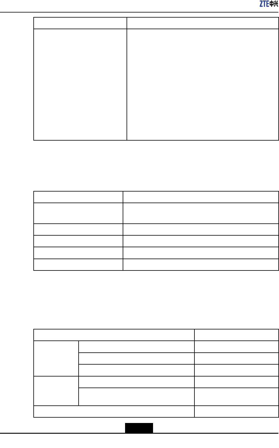
TheZXSDRR8860cabinetisfullysealed.Thetopandbottomenclosuresareunited
byananti-theftscrewwithtwohingesasstopblocks.Thetopenclosureisequipped
withahandletofacilitateconveyanceandinstallation.Areservedengineeringinstallation
positiononthebottomenclosuremakesiteasytoinstallthecabinetundervariousworking
environmentsbyusinginstallationaccessories.
Figure2-1showstheZXSDRR8860cabinetexternalstructure.
2-1
SJ-20100722143906-001|08/30/2010ZTEProprietaryandCondential
ZXSDRR8860TechnicalManual
Figure2-1CabinetOuterStructure
1.BottomEnclosure2.Hinge3.TopEnclosure
EnclosureDimensionDescription
Table2-1liststhedimensionsoftopandbottomenclosures.
Table2-1ZXSDRR8860CabinetEnclosureDimensions
EnclosureDimension(WxHxD)
Top320mm×370mm×72mm
Bottom320mm×500mm×100mm
2.1.2IndoorStructure
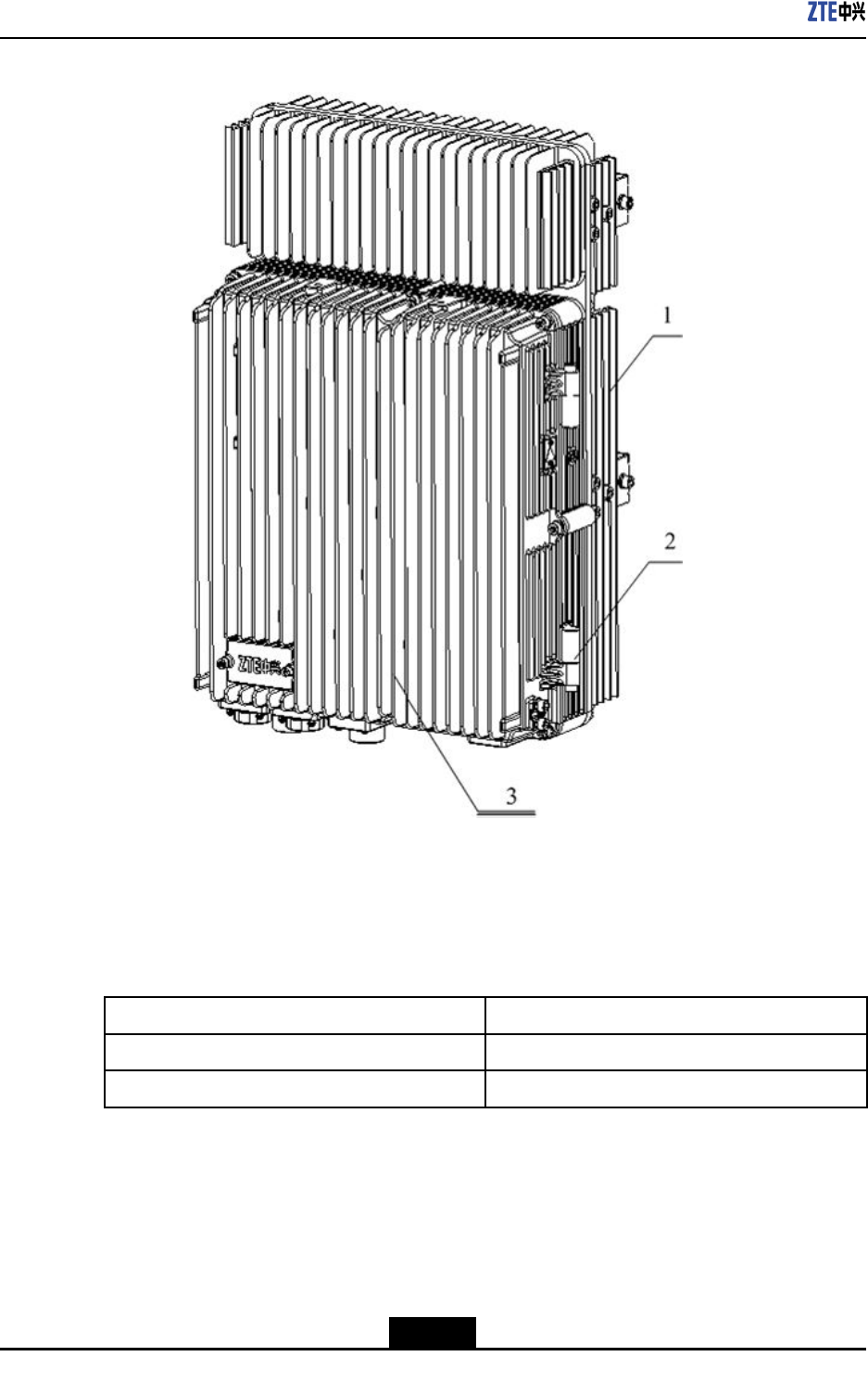
TheZXSDRR8860cabinetconsistsoffourmodulessuchasFLmodule,PAmodule,DC
Powermodule,andTRmodule.
Figure2-2showstheZXSDRR8860cabinetinternalstructure.
2-2
SJ-20100722143906-001|08/30/2010ZTEProprietaryandCondential
Chapter2HardwareDescriptions
Figure2-2ZXSDRR8860CabinetInternalStructure
1.TRModule
2.DCPowerModule
3.PAModule
4.FLModule
2.1.3VentilationandHeat-dissipationPrinciples
TheZXSDRR8860cabinetisnaturallycooledthroughaircoolednsonthetopandbottom
enclosures.Naturalheatdissipationreplacesheatexchangerrequirementforoutdoor
application.Inaddition,aheatsinkisequippedatthebottomofthecabinettoenhance
heatdissipation.
2.2Modules
2.2.1ModulesList
TheZXSDRR8860cabinetconsistsoffourmodulessuchas:
lFLmodule
lPAmodule
lDCPowermodule
lTRmodule
2.2.2FilterLNA(FL)
ThefunctionsoftheFilterLNA(FL)moduleareasfollows.
lPerformslteringandlownoiseamplicationofthereverseCDMAsignalfromthe
antenna.
2-3
SJ-20100722143906-001|08/30/2010ZTEProprietaryandCondential

ZXSDRR8860TechnicalManual
lFilterstheforwardRFsignaltobesent.
lReportsLNAalarmstotheTR.
lInthecaseofmain/diversitycombinedcabinets,themainreceiveLNAoutputendof
theFLhasthepowersplitterfunctionandreservesanexternalport(RXout).
2.2.3Transceiver(TR)
TheTransceiver(TR)isthemaincontrolmoduleofZXSDRR8860.Itperforms
communication,control,alarm,andversionmanagementforZXSDRR8860.
FollowingarethefunctionsoftheTRmodule.
lForwardlinkprocessing
àConversionfrombasebandsignaltoRFsignal
àConversionofoutputIQdataformat
àPowercalibrationanddetectionprocessing
àPeakclipping/digitalpre-distortionprocessing
àDigitalIFprocessing
àGainadjustment(calibration)
lReverselinkprocessing
àConversionfromRFsignaltobasebandsignal
àDigitalIFprocessing
àRSSIandRABreport
àIn-bandanti-interferencefunction
àSpectrumreport
àAutomaticgaincontrol(AGC)
àOutputIQdataformatconversion
àSupportsswitchingbetweendifferentreceivechannelsignalsinthecaseof
main/diversitycombinedcabinets
lClockprocessing
PerformsclockrecoveryfordataontheCPRIbetweentheZXSDRR8860andthe
BBUgeneratingareferenceclocksourceandperformsphaselockforthereference
clockbyutilizingalocalhigh-stabilityclock.Theworkingclocksgeneratedinclude
themasterclock,frame-frequencyclock,digitalprocessingclock,andRFbaseband
clock.
lMonitoring
àPAforwardpowerdetectionfunction:whenthetemperaturethresholdis
exceeded,theTRreportstherelevantalarmandcontrolsthePAthroughthePA
outputenable/disablesignal.
2-4
SJ-20100722143906-001|08/30/2010ZTEProprietaryandCondential

Chapter2HardwareDescriptions
àPAreversedpower(standingwaveratio)detectionfunction:whenthe
temperaturethresholdstandingofthewaveradioisexceeded,theTRreports
therelevantalarmandcontrolsthePAthroughthePAoutputenable/disable
signal.
àPAtemperaturedetectionfunction:Whenthetemperaturethresholdisexceeded,
theTRreportstherelevantalarmandcontrolsthePAthroughthePAoutput
enable/disablesignal.
àPAoutputenable/disable
àTRtransmitoutputpowerdetection
àFLtwo-channelLNAalarmdetectionandreport
àDCPowerinputundervoltage/overvoltagealarmdetectionandreport
àDCPoweroutputundervoltage/overvoltagealarmdetectionandreport
àDCPoweroutputovercurrentalarmdetectionandreport
àSystemenvironmentmonitoring
àCPRIself-testalarm
àKeychipself-testalarm
2.2.4PowerAmplifier(PA)
ThePowerAmplier(PA)moduleperformsthefollowingfunctions:
lAmpliesdownlinkRFsignalinputviatheTRandthensendsthesignaltotheFL.
lProvidesdigitalpre-distortionfeedbacksignalsfortheTR.
lProvidesaPAoutputenable/disableinterface.
2.2.5Power
TheDCPowermoduleconverts-48VDCinputpowersupplytoDCpowersupplyrequired
bythePA,TR,orFLmodules.
2.3ExternalCables
2.3.1DCPowerCable
The4-corecableisusedasDCpowercableinZXSDRR8860.Itismadeaccordingto
theon-sitesurveyrequirement.
Oneendofthecableissolderedwithastraightroundconnectorwhiletheotherendis
bare,withalabelindicatingsignaldenition.
Figure2-3showsthestructureoftheDCpowercable.
2-5
SJ-20100722143906-001|08/30/2010ZTEProprietaryandCondential
ZXSDRR8860TechnicalManual
Figure2-3DCPowerCableStructure
Table2-2describesthecorrespondencebetweencorecolorsoftheDCpowercableand
signals.
Table2-2ColorsCorrespondencebetweenDCPowerCableandSignals
CorecolorSignal
Blue-48V
Black-48VGND
Note:
lForthe4-corecable,makethetwobluecoresinparallelwitheachotherandthetwo
blackcoresinparallelwitheachother.Thebluecoresrepresent-48Vandtheblack
onesindicate-48VGND.
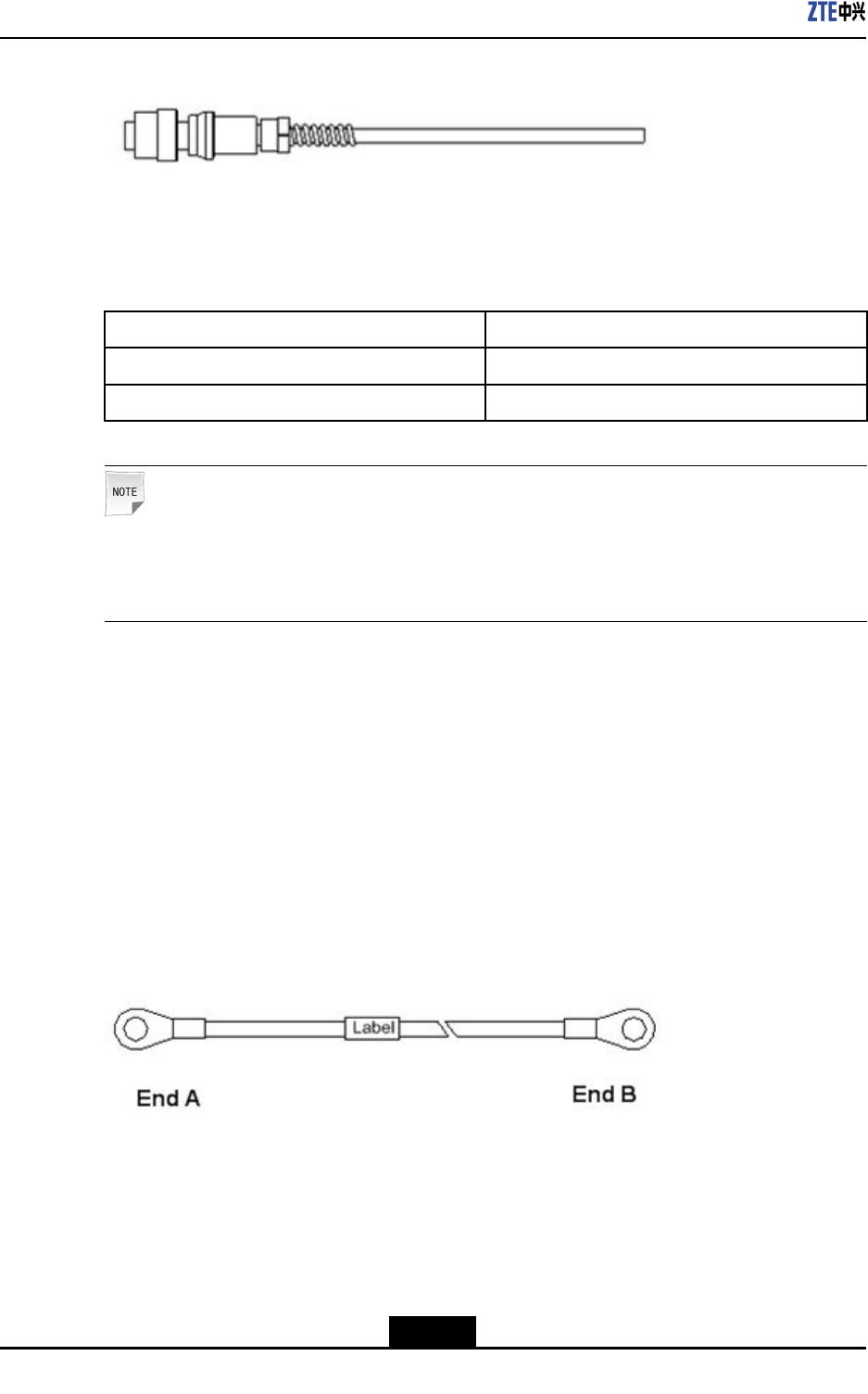
2.3.2GroundingCable
Thegroundingcableconnectsdeviceswiththegroundingbarintheequipmentroom.It
providessystemgroundtopreventdevicesfromstaticdamage,andmakingsuredevices
runreliably.
TheZXSDRR8860groundingcableisastandardre-resistantcableadopting(yellow–
and-green)coreconductor,with10mm2cross-sectionalarea.Bothendsofthecableare
thecircularbarecopperlugconnectors.
Figure2-4showsthestructureofthegroundingcable.
Figure2-4GroundingCableStructure
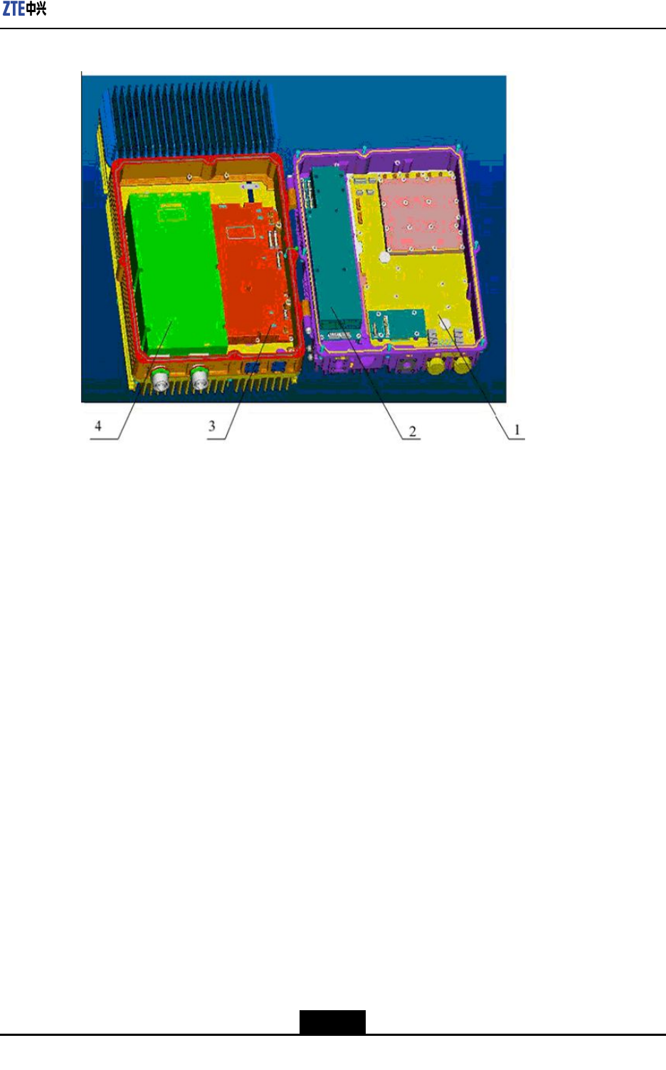
2.3.3AISGControlCable
TheAISGcontrolcableconnectstheAISGdevicetotheAISGportontheZXSDRR8860
cabinet.Thebothendsofthecableare8-coreaerialconnectorsthatmeettheIEC
60130-9-EDstandard.Figure2-5showstheoutlineofthecable.
2-6
SJ-20100722143906-001|08/30/2010ZTEProprietaryandCondential
Chapter2HardwareDescriptions
Figure2-5OutlineoftheAISGcontrolcable
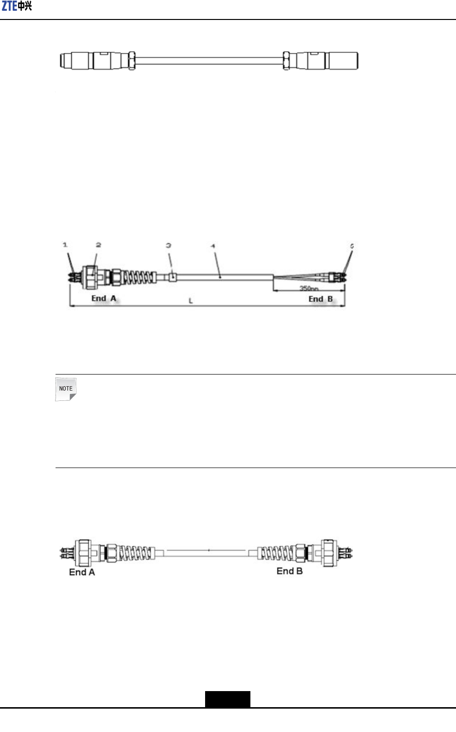
2.3.4OpticalFiberCable
Therearetwotypesofopticalbersused,oneisusedtoconnectwithBBUwhileotheris
usedtoconnectcascadedcabinets.TheZXSDRR8860adoptssinglemode2-coreber
tailandmultimodeber.Thetaillengthdependsontheactualsituation.
Figure2-6showsthestructureofthebertailusedtoconnectBBU.
Figure2-6FiberCableUsedtoConnectBBU.
1.DLCopticalconnector
2.Outdoorfibersealingnut
component
3.Label
4.Singlemode2-corefiber
tail
5.LCopticalconnector
Note:
Theberisusedinoutdoorenvironments.Thebersheathshouldbewaterproofand
anti-ultraviolet.Theworkingtemperatureshouldbeintherangeof-40℃~+80℃.The
sheathisofblackcolor.
Figure2-7showstheopticalbercableusedforcascadedcabinets.
Figure2-7FiberUsedforCascadedCabinets
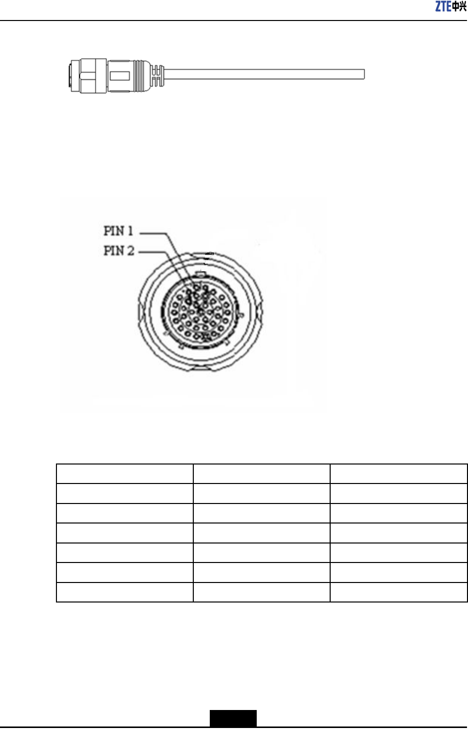
2.3.5EnvironmentMonitoringCable
Theenvironmentmonitoringcableservesasinput/outputdrycontactsandisusedto
transmitRS485monitoringsignals.Figure2-8showstheoutlineofthecable.
2-7
SJ-20100722143906-001|08/30/2010ZTEProprietaryandCondential
ZXSDRR8860TechnicalManual
Figure2-8EnvironmentMonitoringCable
OneendoftheenvironmentmonitoringcablethatjoinstheZXSDRR8860is37-core
aerialconnector,whichmeetstheGJB599IIIstandard.Figure2-9showstheoutlineofthe
connector.
Figure2-9OutlineofConnector
Table2-3describestheconnectorpinsandconnectingcores.
Table2-3EnvironmentMonitoringCablePinsandConnectingCoresDescription
PinCorecolorSignaldescription
15/16Whiteandblue/blueDrycontact4-/+
17/18Whiteandorange/orangeDrycontact3-/+
19/20Whiteandgreen/greenDrycontact2-/+
21/22Whiteandbrown/brownDrycontact1-/+
23/24Redandblue/blueRS485received
25/26Redandorange/orangeRS485transmission
2.3.6CarrierSectorExtensionCable
ThecarriersectorextensioncableisusedtoconnecttwoZXSDRR8860cabinetsto
increasethenumberofcarriersectors.Figure2-10showsthestructureofthecarrier
sectorextensioncable.EndAandEndBareNtypemaleconnectors.
2-8
SJ-20100722143906-001|08/30/2010ZTEProprietaryandCondential
Chapter2HardwareDescriptions
Figure2-10CarrierSectorExtensionCable
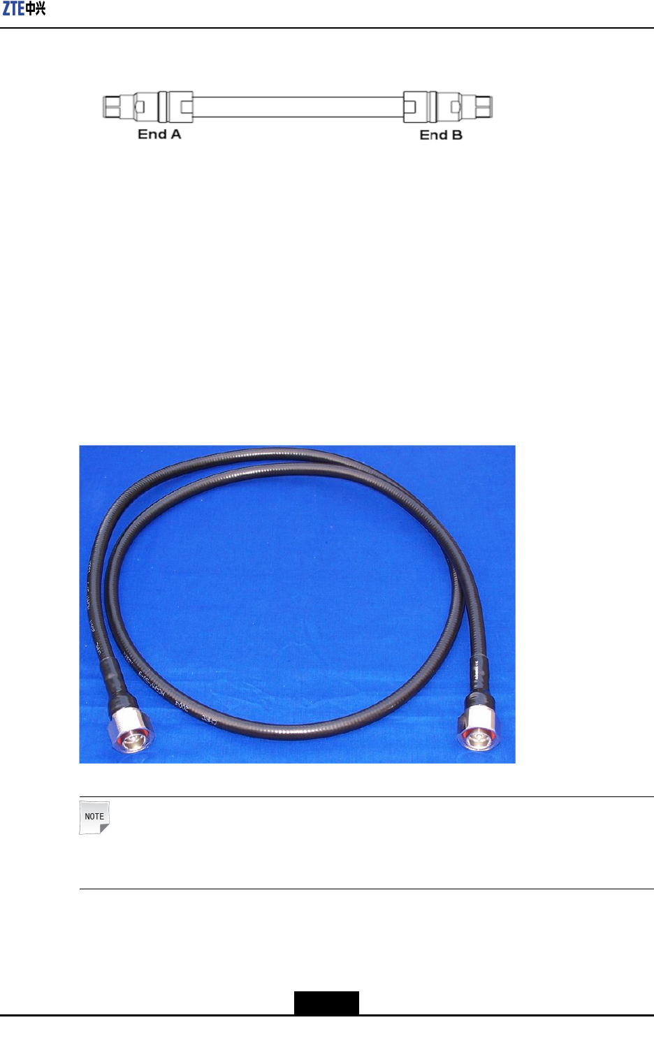
2.3.7RFJumperCable
RFjumpercableisusedtotransfersignalsbetweenZXSDRR8860cabinetandantenna,
betweenZXSDRR8860cabinetandmainfeedercable,andbetweenmainfeedercable
andantenna.
WhenthedistancebetweenantennaandZXSDRR8860cabinetislessandtheadopted
feedercableisof1/2in.then,thejumpercableisnotused,ratherZXSDRR8860cabinet
isdirectlyconnectedwiththefeedercableandfeedercableisconnectedtotheantenna.
Iftheadoptedfeedercableisof7/8in.or5/4in.thenjumperisused.Figure2-11shows
theRFjumpercable.
Figure2-11RFJumperCable
Note:
ThelengthoftheRFjumpercableisdeterminedaccordingtotheactualsituation.
2-9
SJ-20100722143906-001|08/30/2010ZTEProprietaryandCondential
ZXSDRR8860TechnicalManual
2.4MainAntennaFeederSystem
2.4.1MainAntennaFeederSystemStructure
ThetypicalcongurationsofZXSDRR8860mainantennafeedersystemdescribedbelow
includes:
lZXSDRR8860conguredwithcommonantenna
lZXSDRR8860conguredwithcommonantennaandAISGdualtoweramplier
lZXSDRR8860conguredwithelectricallytunedantenna(1)
lZXSDRR8860conguredwithelectricallytunedantenna(2)
lZXSDRR8860conguredwithelectricallytunedantenna,AISGdualtoweramplier
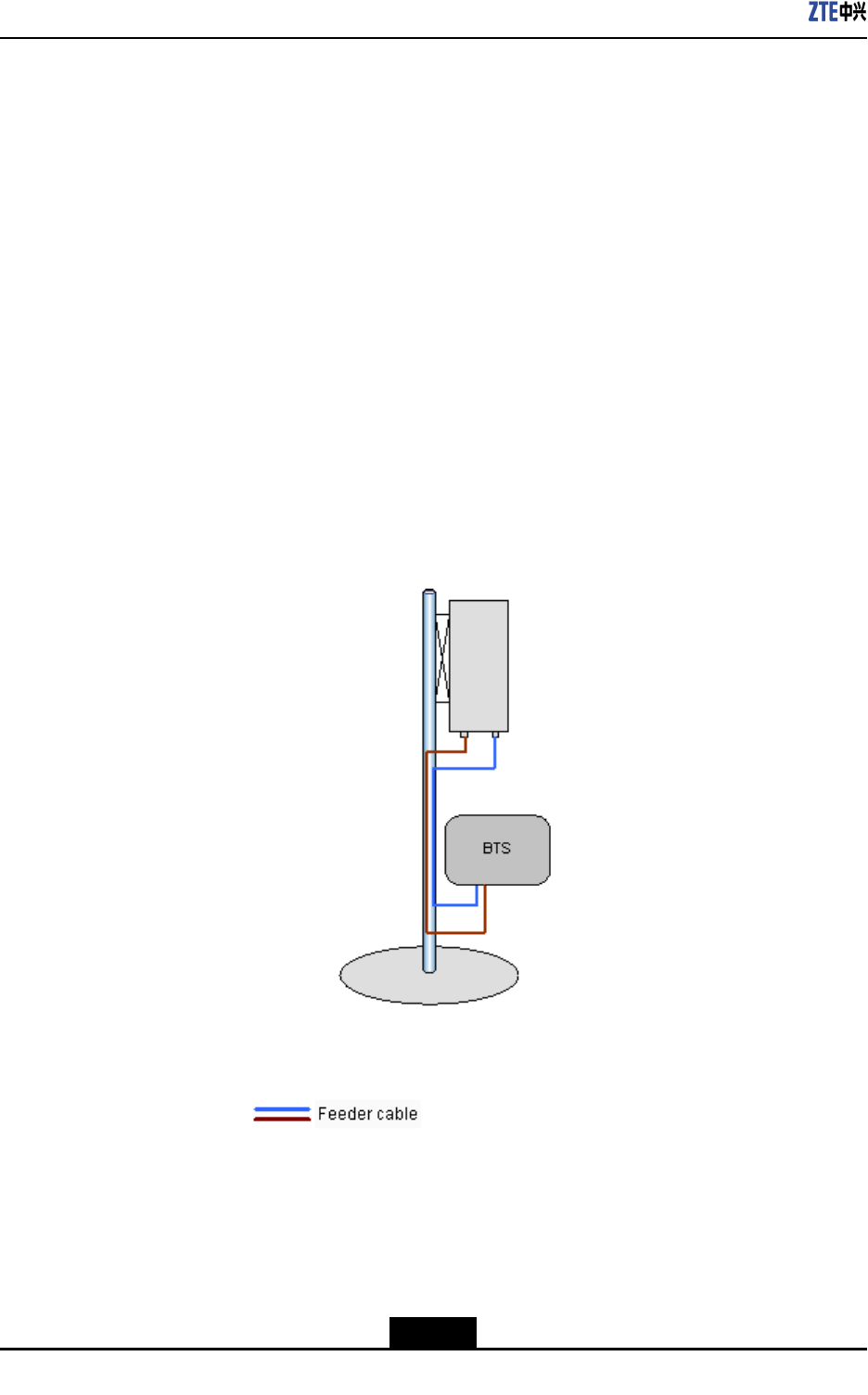
ZXSDRR8860conguredwithcommonantenna
Inthisconguration,generallyZXSDRR8860installationpositionisnearantennaand
theyareallinstalledonthebuildingtop.ZXSDRR8860isconnectedtotheantennaby
1/2″feederdirectly,occasionally5/4″or7/8″feederisadopted,asshowninFigure2-12.
Figure2-12ZXSDRR8860ConguredwithCommonAntenna
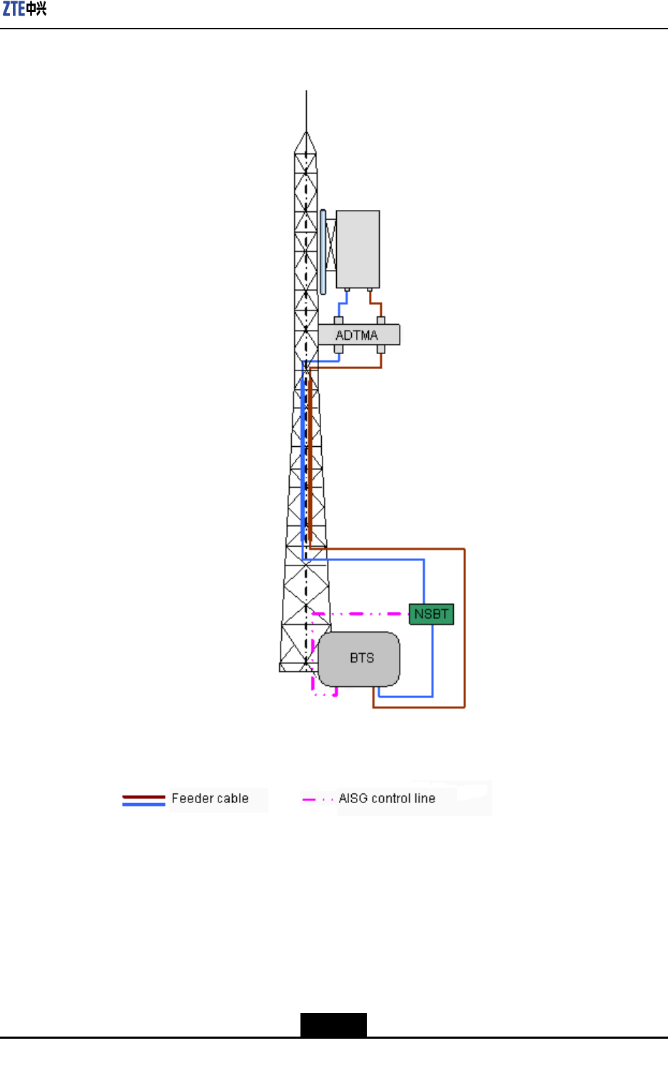
ZXSDRR8860conguredwithcommonantennaandAISGdualtoweramplier
Inthisconguration,generallyZXSDRR8860isinstalledonthetower.ZXSDRR8860is
connectedtotheantennaby5/4″or7/8″feeder,asshowninFigure2-13.
2-10
SJ-20100722143906-001|08/30/2010ZTEProprietaryandCondential
Chapter2HardwareDescriptions
Figure2-13ZXSDRR8860ConguredwithCommonAntenna,AISGDualTower
Amplier
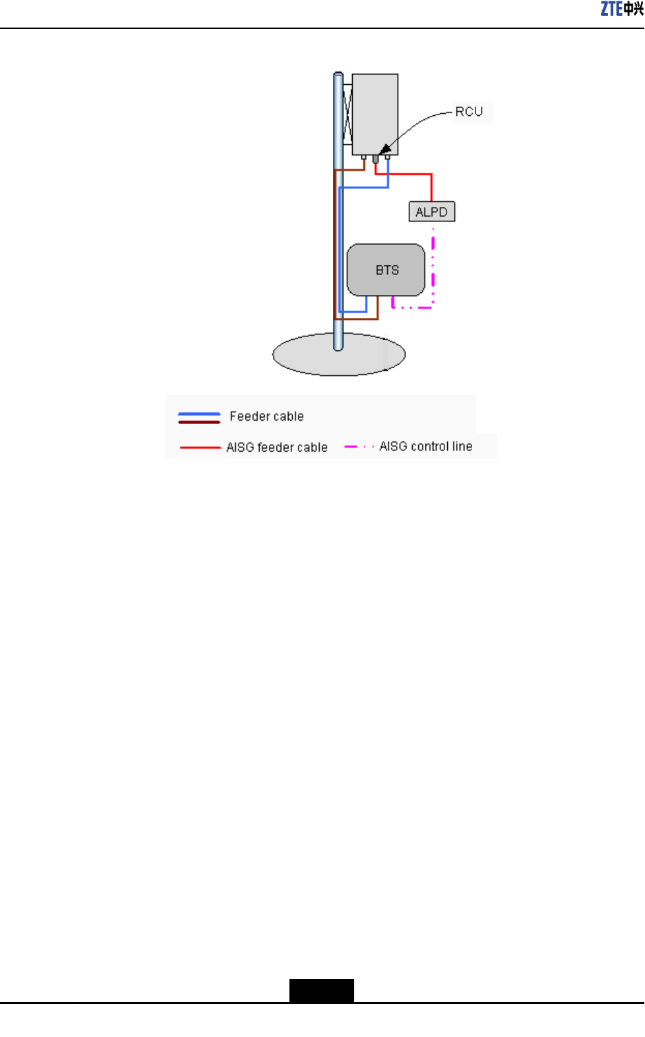
ZXSDRR8860conguredwithelectricallytunedantenna(1)
Inthisconguration,generallyZXSDRR8860installedneartheantennaonthebuilding
top.ZXSDRR8860isconnectedtotheantennaby1/2″feederdirectly,occasionally5/4″or
7/8″feederisadopted,asshowninFigure2-14.
2-11
SJ-20100722143906-001|08/30/2010ZTEProprietaryandCondential
ZXSDRR8860TechnicalManual
Figure2-14ZXSDRR8860ConguredwithElectricallyTunedAntenna(1)
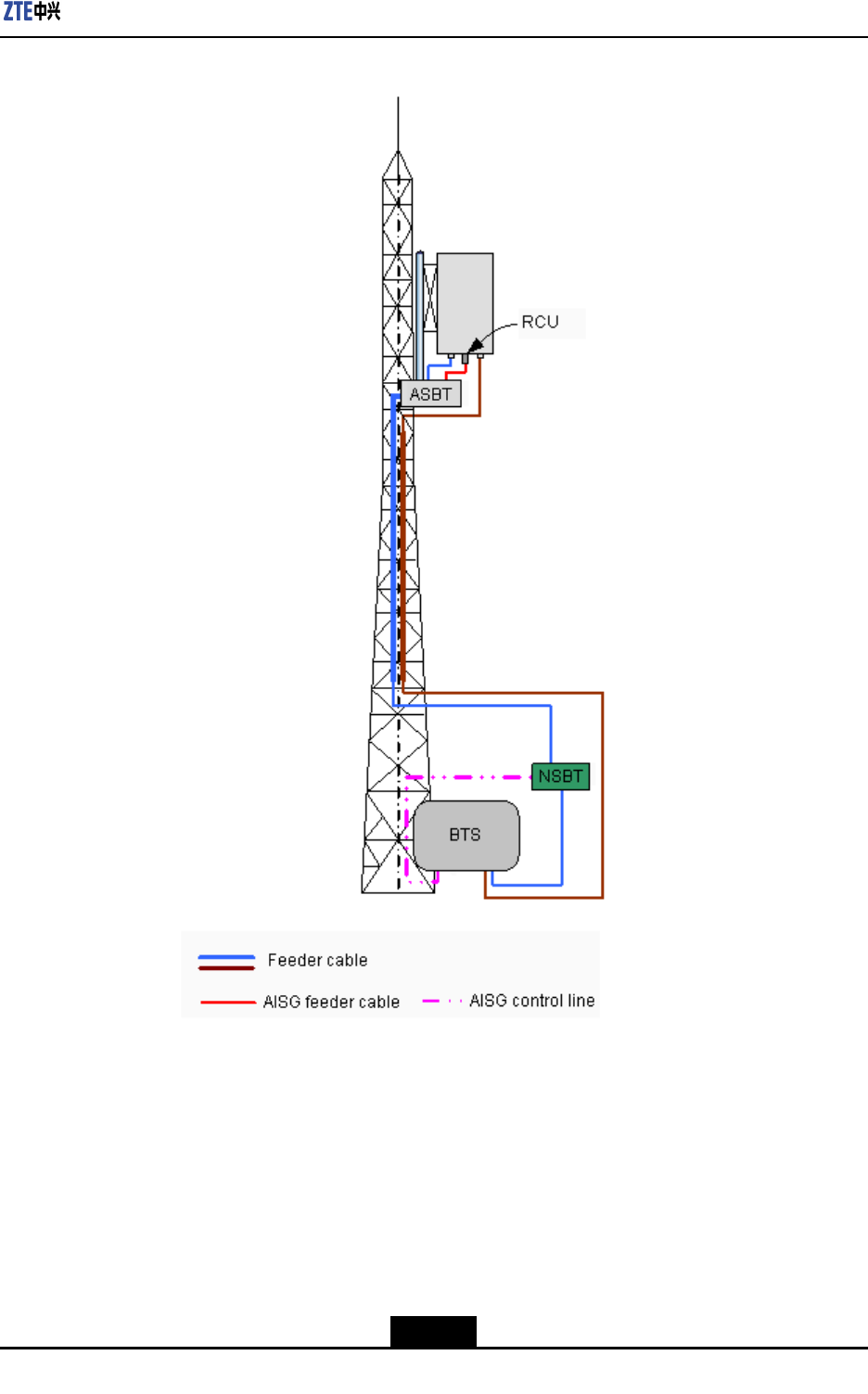
ZXSDRR8860conguredwithelectricallytunedantenna(2)
Inthisconguration,generallyZXSDRR8860isinstallednearthetopofthetower.ZXSDR
R8860isconnectedtotheantennaby5/4″or7/8″feederisadopted,asshowninFigure
2-15.
2-12
SJ-20100722143906-001|08/30/2010ZTEProprietaryandCondential
Chapter2HardwareDescriptions
Figure2-15ZXSDRR8860ConguredwithElectricallyTunedAntenna(2)
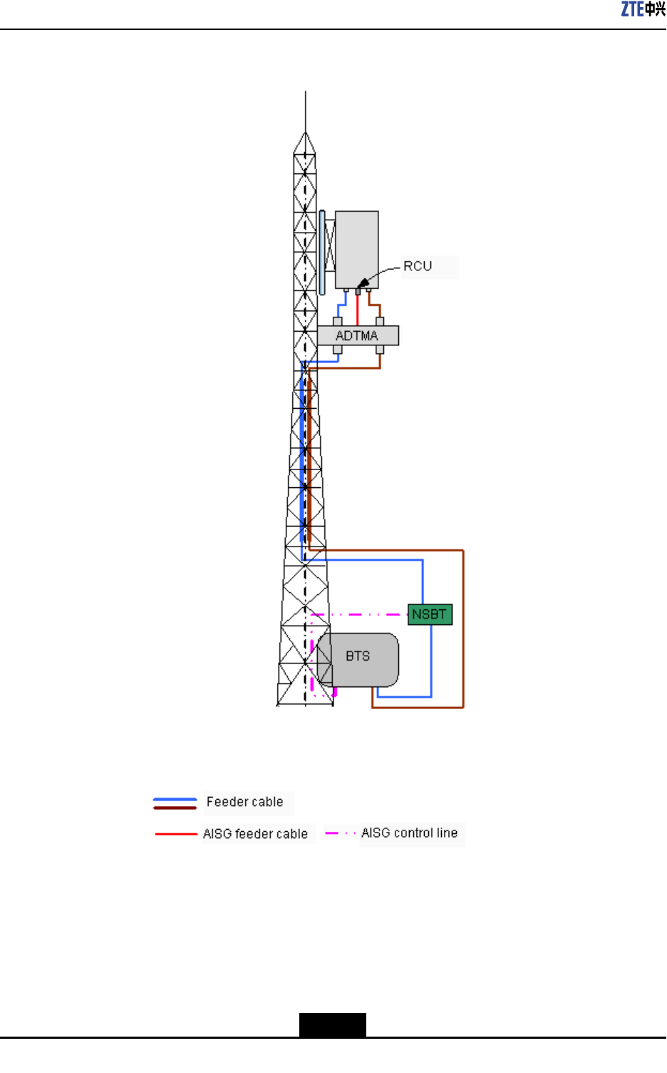
ZXSDRR8860conguredwithelectricallytunedantenna,AISGdualtoweramplier
Inthisconguration,generallyZXSDRR8860isinstallednearthetopofthetower.ZXSDR
R8860isconnectedtotheantennaby5/4″or7/8″feederisadopted,asshowninFigure
2-16.
2-13
SJ-20100722143906-001|08/30/2010ZTEProprietaryandCondential
ZXSDRR8860TechnicalManual
Figure2-16ZXSDRR8860ConguredwithElectricallyTunedAntennaandAISGDual
TowerAmplier
2.4.2Antenna
TheZXSDRR8860antennafeedersystemadoptscommonantennaorelectricalantenna.
Fortheelectricalantenna,youcanadjustthelevertocontroltheembeddedadjusterand
thustotunethedowntiltangleoftheantenna.Thetiltreectsthedirectionfromwhichthe
2-14
SJ-20100722143906-001|08/30/2010ZTEProprietaryandCondential

Chapter2HardwareDescriptions
antennareceivesthestrongestsignals.Thetiltoftheuni-directionalantennacanbetuned
mechanically,andelectricaltiltisusedtotunetheomni-directionalantenna.
Theprincipleoftheelectricaltiltisasfollows:
Theadjustmentofthephaseoftheantennaarrayvibratorchangesthemaximumvertical
andhorizontalcomponentsandalterssynthesizedeldstrength,thusmakingthevertical
patternoftheantennadeclining.Becausetheantennaeldstrengthincreasesor
decreasessimultaneouslyinalldirections,whichensuresthattheantennapatternhardly
varieswiththetilt.Thisdiminishesthecoverageofthemainlobeandensuresthatno
interferenceoccurswhenthecoverageofthewholepatterndecreasesinitsservicearea.
2.4.3FeederStructure
ThefeederisusedtoreceiveandtransmitradioRFsignalsbetweentheantennaandthe
ZXSDRR8860.Therearemanytypesoffeedercablessuchas1/2inchand7/8inch
feedercable.
WhenthedistancebetweentheZXSDRR8860cabinetandantennaisless,then1/2inch
feedercableisused.Inthiscase,theZXSDRR8860cabinetisdirectlyconnectedtothe
1/2inchfeederand1/2inchfeedercableisconnectedtoantenna.
WhenthedistancebetweentheZXSDRR8860cabinetandantennaismore,then7/8
inchfeedercableisused.Inthiscase,ZXSDRR8860cabinetisrstconnectedtothe
jumper,thenjumperisconnectedto7/8inchfeedercable,and7/8inchfeedercableis
againconnectedtojumperandlastlyjumperisconnectedtoantenna.
TheantennamayhaveNtypeorDINtypeinterface.Thefeederisadaptedtofemaleand
maleNconnectors.UsuallybothendsofthedeliveredfeederaremaleNconnectorto
facilitateon-siteinstallation.
2-15
SJ-20100722143906-001|08/30/2010ZTEProprietaryandCondential

ZXSDRR8860TechnicalManual
Thispageintentionallyleftblank.
2-16
SJ-20100722143906-001|08/30/2010ZTEProprietaryandCondential
Chapter3
ProtocolInterface
Description
TableofContents
NetworkReferenceModel..........................................................................................3-1
UmInterface..............................................................................................................3-2
Baseband—RFInterface............................................................................................3-6
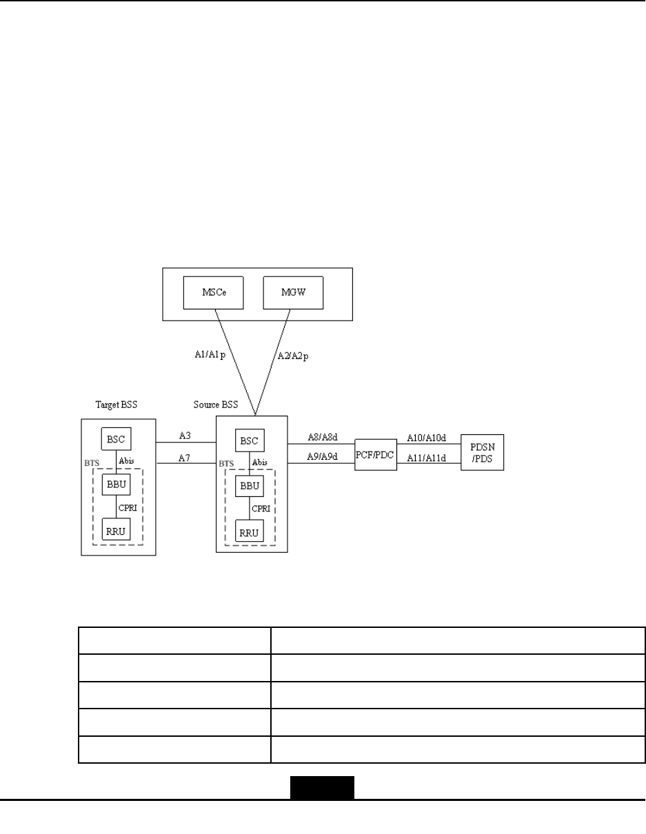
3.1NetworkReferenceModel
Figure3-1showsthenetworkreferencemodeloftheCDMA20001xnetwork.
Figure3-1CDMA20001xNetworkReferenceModel
ThedescriptionoftheinterfacesinFigure3-1aredescribedinT able3-1.
Table3-1InterfaceDescription
InterfaceDescription
AbisInterfacebetweenBSCandBTS
CPRIInterfacebetweenBBUandRRUofthedistributedbasestation
A1/A1pSignalinginterfacebetweenMSCe/MGWandBSC
A2/A2pServiceinterfacebetweenMSCe/MGWandBSC
3-1
SJ-20100722143906-001|08/30/2010ZTEProprietaryandCondential
ZXSDRR8860TechnicalManual
InterfaceDescription
A3ImplementssofthandoffbetweendifferentBSCs(focusingon
themediaplane).
A7ImplementssofthandoffbetweendifferentBSCs(focusingon
thecontrolplane).
A8/A8dImplementsdatatransmissionbetweenBSSandPCF/PDC.
A9/A9dImplementssignalingtransmissionbetweenBSSandPCF/PDC
A10/A10dImplementsdatatransmissionbetweenPCFandPDSN,and
betweenPDCandPDS.
A11/A11dImplementssignalingtransmissionbetweenPCFandPDSN,and
betweenPDCandPDS.
3.2UmInterface
TheUminterfaceistheairinterfacebetweenMobileStation(MS)andBaseTransceiver
Station(BTS),complyingwiththeIS-2000ReleaseAstandardsandtheIS-856-Astandard.
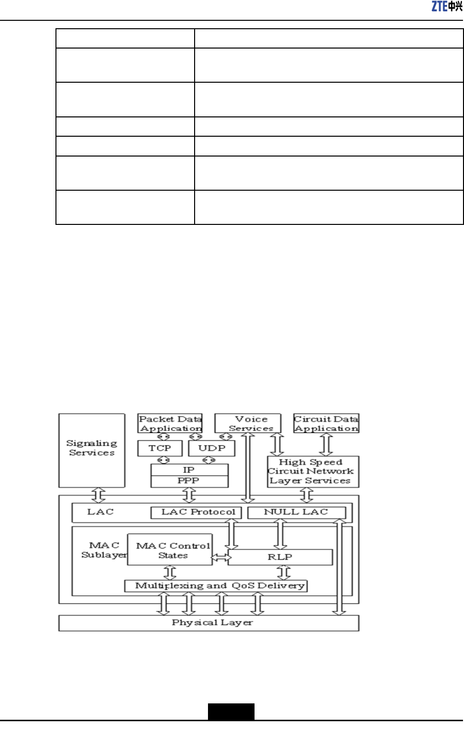
CDMA20001xUmInterface
TheCDMA20001xUminterfaceiscomposedofphysicallayer,datalinklayerand
uppermostlayer.Figure3-2showstheprotocolreferencemodel.
Figure3-2CDMA20001xUmInterfaceProtocolReferenceModel
lThephysicallayerisabottomlayer,coveringvariousphysicalchannels.Itprovides
basicradiochannelstotransmitinformationofupperlayers.
3-2
SJ-20100722143906-001|08/30/2010ZTEProprietaryandCondential
Chapter3ProtocolInterfaceDescription
lThedatalinklayercomprisesofMediumAccessControl(MAC)sublayerand
LinkAccessControl(LAC)sublayer.TheMACsublayerimplementsthemapping
betweenlogicalchannelsandphysicalchannelsanddeliverstheRadioLinkProtocol
(RLP)function.TheLACsublayerperformsauthentication,automaticrequest
retransmission,addressing,segmentandreassembly.
lTheuppermostlayerprovidessignalingservice,voiceservice,packetdataapplication
andcircuitdataapplication,andimplementsradioresource,mobilityandconnection
managementoftheairinterfacethroughsignalingservice.
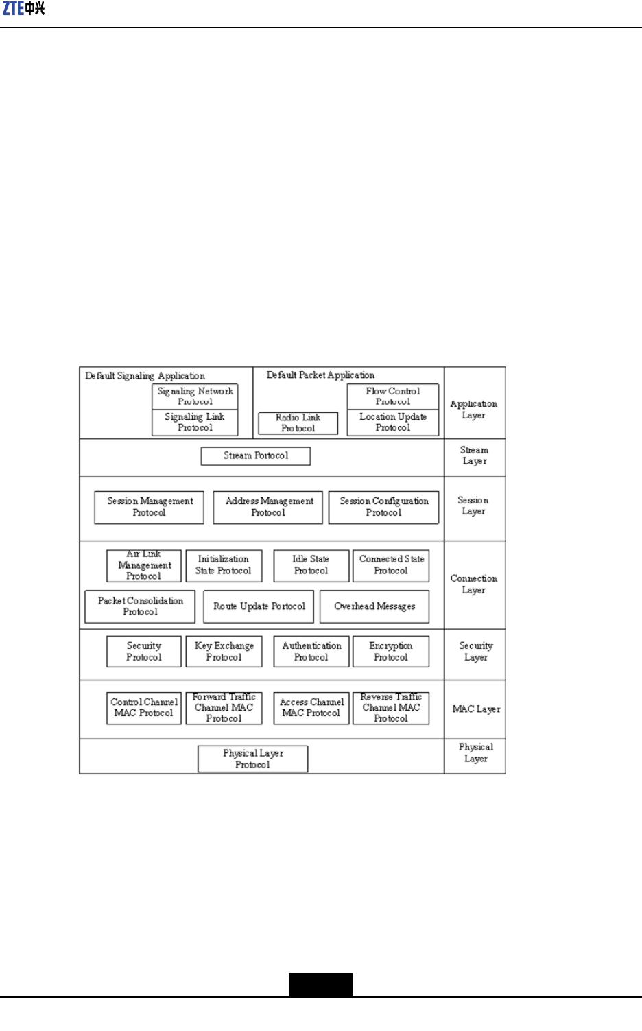
CDMA20001xEV-DOUminterface
TheCDMA20001xEV-DOUminterfaceisdividedintoapplicationlayer,streamlayer,
sessionlayer,connectionlayer,securitylayerandphysicallayer.TheUminterfacemeets
theIS-856protocolstandard.Everylayerdenesoneormoreprotocolstorealizeits
function.Figure3-3illustratestheoverallprotocolreferencemodel.
Figure3-31xEV-DOUmInterfaceProtocolReferenceModel
lApplicationlayer
Theapplicationlayerprovidesmultipleapplications,suchasDefaultSignaling
ApplicationfortransmittingairinterfacemessagesandDefaultPacketApplicationfor
transmittingdata.TheDefaultSignalingApplicationdenestwoprotocols,Signaling
NetworkProtocol(SNP)andSignalingLinkProtocol(SLP).Theprotocolsonall
layersexchangemessagesthroughSNP.SLPimplementsmessagesegment
andassembly,Best-efforttransmission,reliabletransmissionandduplicatepacket
detection.
3-3
SJ-20100722143906-001|08/30/2010ZTEProprietaryandCondential

ZXSDRR8860TechnicalManual
TheDefaultPacketApplicationprovidesabytestreamtotransmitpacketdata
betweentheterminalandthenetwork.Itincludesthreeprotocols.
àFlowControlProtocolprovidestheowcontrolfunctionfordatastream.
àRadioLinkProtocolimplementsbytestreamretransmissionandduplicatepacket
detection,andprovidesareliabledatalinkforupperapplications.
àLocationUpdateProtocolprovideslocationupdateprogramandcorresponding
messagesformobilitymanagementofpacketapplication.
lStreamlayer
Thestreamlayerdeliversthefollowingfunctions:
àItprovidesthearchitectureofdatapacketsovertheconnectionapplicationlayer
bymeansofdatastreamauthentication.
àItdistinguishesprioritiessignalsanduserservicesaccordingtothedata
encapsulationprotocoloftheconnectionlayer.
àItconnectsuserstosignalservice.
àItallocatesindependentdatastreamtoapplicationsofdifferentQoSs.
lSessionlayer
Thesessionlayercontainsaseriesofprotocolsusedforsessionnegotiationbetween
theterminalandthenetwork.Inthe1xEV-DOsystem,asessionindicatesastate
jointlymaintainedbetweenAccessT erminal(AT)andAccessNetwork(AN).Itincludes
addressUATIdistributedtotheterminal,protocolsetdeterminedbytheterminaland
thenetworkforairinterfacecommunication,protocolcongurationsintheprotocolset
andcurrentterminallocation.Thesessionlayerdenesthreeprotocols:
àSessionManagementProtocolactivatesotherprotocolsonthelayer,ensures
sessionvalidityandclosessessions.
àAddressManagementProtocolmanagesterminaladdress(UATI)distribution.
àSessionCongurationProtocol(SCP)performssessionownegotiation.Inthe
1xEV-DOsystem,SCPnegotiatestheprotocolusedforcommunicationbetween
theterminalandthenetwork,andhowtosetprotocolparameters.
lConnectionlayer
Theconnectionlayercontrolstheairlinkstate.Inthe1xEV-DOsystem,anenabled
linkbetweenATandANmeanstheATisallocatedwithRPC,RTCandFTC(FTCis
thetimedivisionchannelsharedbyallthesubscriberswithopenconnectionsinthe
sector).
lSecuritylayer
Thesecuritylayerdeliversthefollowingfunctions:
àKeyexchange.Itprovidesaprocedurefortheterminalandthenetworkto
exchangekeysthatareusedforauthenticationandencryption.
3-4
SJ-20100722143906-001|08/30/2010ZTEProprietaryandCondential

Chapter3ProtocolInterfaceDescription
àAuthentication.Itprovidesaprocedurefortheterminalandthenetworkto
authenticateover-the-airservices.
àEncryption.Itprovidesaprocedurefortheterminalandthenetworktoencrypt
over-the-airservices.
Thesecuritylayercoversfourprotocols,amongwhichKeyExchangeProtocol,
AuthenticationProtocolandEncryptionProtocoldenethethreefunctionsmentioned
aboverespectivelywhileSecurityProtocolprovidespublicvariablesforAuthentication
ProtocolandEncryptionProtocol.
lMAClayer
TheMAClayerdenestherulesformanagingcontrolchannel,accesschannel,
forwardtrafcchannelandreversetrafcchannel.Itcontainsfourprotocols,as
describedbelow:
àControlChannelMACProtocolconstructsControlchannelMAClayerpacket
fromoneormoreSecuritylayerpackets,controlspacketschedulingand
transmissionruleofchannelsandregulateshowtheterminalcapturesthe
controlchannelandreceivescontrolchannelpackets.
àAccessChannelMACProtocoldenesthattheterminalsendstimingmessages
andpowerfeaturesovertheaccesschannel.
àForwardTrafcChannel(FTC)Protocolregulateshowtocontroltherateofthe
FTCthroughtheDRCandhowtosupportthexedratemodeandvariablerate
modeoftheFTC.
àReverseTrafcChannel(RTC)Protocolregulateshowtheterminalassiststhe
networktocapturetheRTCandhowtheterminalandthenetworkchooseRFC
rate.
lPhysicallayer
Thephysicallayerdenesstructure,frequency,poweroutput,
modulation/demodulationandcoding/decodingoftheforward/reversechannel.
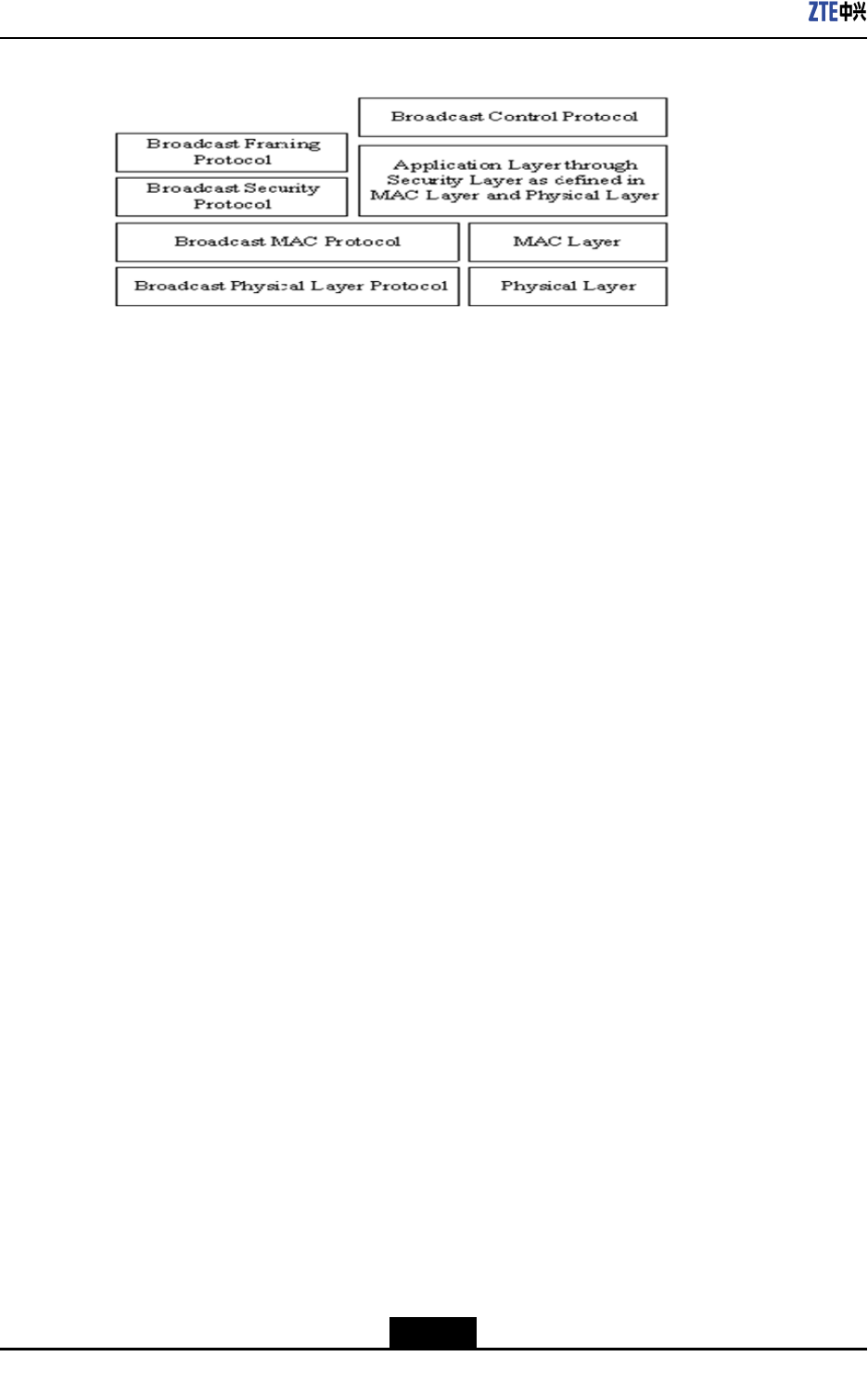
BCMCSUmInterface
TheBroadcastandMulticastService(BCMCS)Uminterfaceimplementsbroadcastand
multicastservices.Figure3-4showsthestructureoftheBCMCSUminterfaceprotocol
stack.
3-5
SJ-20100722143906-001|08/30/2010ZTEProprietaryandCondential
ZXSDRR8860TechnicalManual
Figure3-4StructureoftheBCMCSUmInterfaceProtocolStack
lBroadcastControlProtocolprocessesBCMCSstreamregistration.TheATsendsthe
streamregistrationrequesttotheANsothattheANcanbroadcastingthestream
continuously.
lBroadcastFramingProtocolencapsulates,segmentsanddelimitsupperlayerpack-
ets.
lBroadcastSecurityProtocolprovidespacketencryptionmechanism.
lBroadcastMACProtocoladdsforwarderrorcorrectingcodestoformErrorControl
Block(ECB)andrelaysMACframestothephysicallayer.Thelayerisresponsibleof
logicalchannelmapping,constructingandsendingbroadcastoverheadmessages.
lBroadcastPhysicalProtocolprovidesalogicalchannelstructure.
3.3Baseband—RFInterface
Thebaseband-RFinterfaceofZXSDRR8860complieswiththecommonpublicradio
interface(CPRI)specication.TheCPRIspecicationwasinstitutedbytheCPRIUnion,
whichisanindustrycooperationorganizationdevotingitselftoinstitutionofinternalradio
interfacespecicationsofradiobasestations.
TheCPRIspecicationdescribesthetransmission,controlandsynchronization
mechanismsofuserdataandcontrolsignaling,deningtheessentialfactorssuchas
transmission,connectionandcontrol.
Fromaviewofthespecicationsystem,theCPRIspecicationcontainsthecontents
ofphysicallayeranddatalinklayer.Itdescribescharacteristicsofelectricalandoptical
interfacesandmultiplexingmechanismsamongvariousdataowsinthematterofthe
physicallayer,andmediaaccesscontrol(MAC),owcontrolandinformationow
protectioninthematterofthedatalinklayer.
3-6
SJ-20100722143906-001|08/30/2010ZTEProprietaryandCondential

Figures
Figure1-1DistributedZTEBTSSolution..................................................................1-1
Figure1-2ZXSDRR8860PositionintheNetwork....................................................1-3
Figure1-3ZXSDRR8860CabinetAppearance........................................................1-3
Figure1-4ZXSDRR8860ExternalInterfaces...........................................................1-6
Figure1-5ZXSDRR8860Wall-MountMode.............................................................1-8
Figure1-6TwoZXSDRR8860CabinetsPole-MountMode......................................1-9
Figure1-7ThreeZXSDRR8860CabinetsPole-MountMode...................................1-9
Figure1-8ZXSDRR8860SystemStructure...........................................................1-10
Figure1-9ZXSDRR8860Baseband-RFInterfaceNetworking...............................1-11
Figure1-10ZXSDRR8860CascadeNetworking....................................................1-12
Figure1-11ZXSDRR8860FrequencyExtensionNetworking.................................1-13
Figure1-12ZXSDRR8860OperationandMaintenance–OMCMode....................1-14
Figure1-13ZXSDRR8860OperationandMaintenanceSystem(LMT
Mode)...................................................................................................1-15
Figure2-1CabinetOuterStructure...........................................................................2-2
Figure2-2ZXSDRR8860CabinetInternalStructure................................................2-3
Figure2-3DCPowerCableStructure......................................................................2-6
Figure2-4GroundingCableStructure......................................................................2-6
Figure2-5OutlineoftheAISGcontrolcable.............................................................2-7
Figure2-6FiberCableUsedtoConnectBBU...........................................................2-7
Figure2-7FiberUsedforCascadedCabinets..........................................................2-7
Figure2-8EnvironmentMonitoringCable.................................................................2-8
Figure2-9OutlineofConnector................................................................................2-8
Figure2-10CarrierSectorExtensionCable..............................................................2-9
Figure2-11RFJumperCable...................................................................................2-9
Figure2-12ZXSDRR8860ConguredwithCommonAntenna..............................2-10
Figure2-13ZXSDRR8860ConguredwithCommonAntenna,AISGDualT ower
Amplier...............................................................................................2-11
Figure2-14ZXSDRR8860ConguredwithElectricallyTunedAntenna(1)............2-12
Figure2-15ZXSDRR8860ConguredwithElectricallyTunedAntenna(2)............2-13
Figure2-16ZXSDRR8860ConguredwithElectricallyTunedAntennaandAISG
DualTowerAmplier.............................................................................2-14
Figure3-1CDMA20001xNetworkReferenceModel................................................3-1
I


Tables
Table1-1ZXSDRR8860Functions..........................................................................1-4
Table1-2ZXSDRR8860ExternalInterfacesDescription..........................................1-6
Table1-3ZXSDRR8860EngineeringIndices.........................................................1-15
Table1-4JD40K085C20H2–K1ZDCLightningBoxTechnicalIndices....................1-16
Table1-5ZXSDRR8860PerformanceIndices.......................................................1-16
Table1-6ZXSDRR8860RFIndices.......................................................................1-17
Table2-1ZXSDRR8860CabinetEnclosureDimensions..........................................2-2
Table2-2ColorsCorrespondencebetweenDCPowerCableandSignals................2-6
Table2-3EnvironmentMonitoringCablePinsandConnectingCores
Description...............................................................................................2-8
Table3-1InterfaceDescription..................................................................................3-1
III

Tables
Thispageintentionallyleftblank.

Glossary
AISG
-AntennaInterfaceStandardsGroup
AN
-AccessNetwork
BBU
-BaseBandUnit
BCMCS
-BroadcastandMulticastService
BSC
-BaseStationController
BSS
-BaseStationSystem
BTS
-BaseTransceiverStation
CDMA
-CodeDivisionMultipleAccess
CPRI
-CommonPublicRadioInterface
DRC
-DataRateControl
FL
-ForwardLink
FL
-FilterLNA
LNA
-LowNoiseAmplier
MAC
-MediumAccessControl
MSCe
-MobileSwitchingCenteremulator
PA
-PowerAmplier
PCF
-PacketControlFunction
V

ZXSDRR8860TechnicalManual
PCFisaboardwhichisresponsibleforthedataselectionbetweenmultiple
reversetrafcchannelsanddatadistributionfromaforwardtrafcchannelto
multiplecells/sectorsduringsofthandoff.
PDSN
-PacketDataServiceNode
RAB
-RadioAccessBearer
RF
-RadioFrequency
RLP
-RadioLinkProtocol
RRU
-RemoteRadioUnit
RSSI
-ReceivedSignalStrengthIndicator
TR
-Transceiver
VI