ZTE CBTSI28C CDMA2000 Compact Base Transceiver Stantion-I2 User Manual Q78 CBTSI28A
ZTE Corporation CDMA2000 Compact Base Transceiver Stantion-I2 Q78 CBTSI28A
ZTE >
User Manual
ZXC10 CBTS
CDMA2000 Compact Base Transceiver
Station
Installation Manual

ZTE CORPORATION
Values Your Comments & Suggestions!

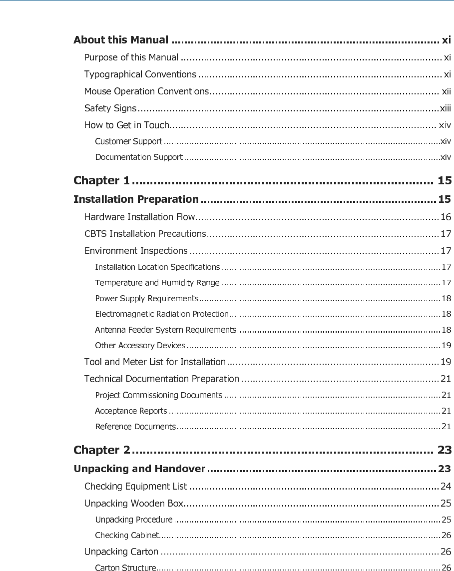
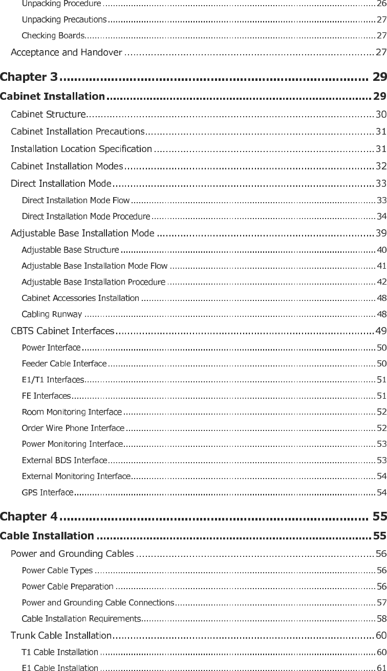
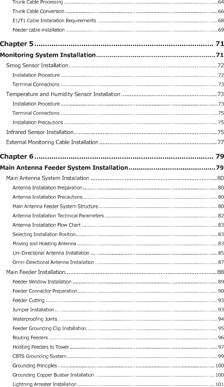
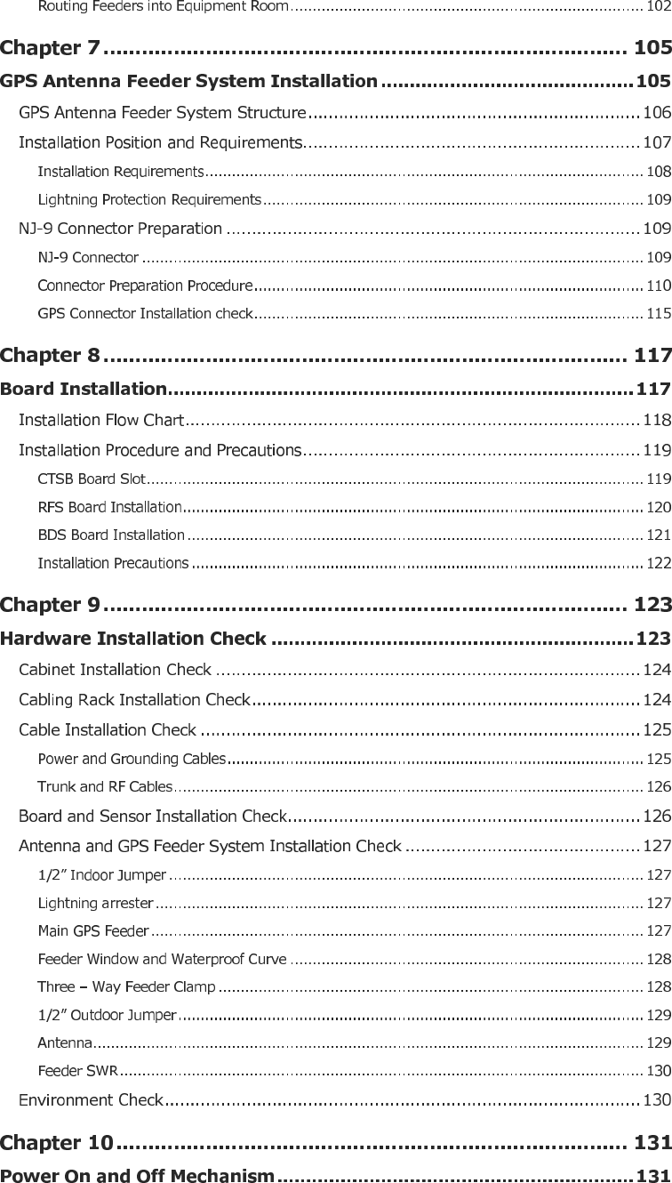
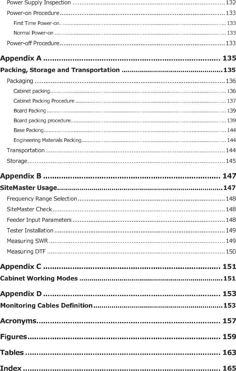
Contents

About this Manual
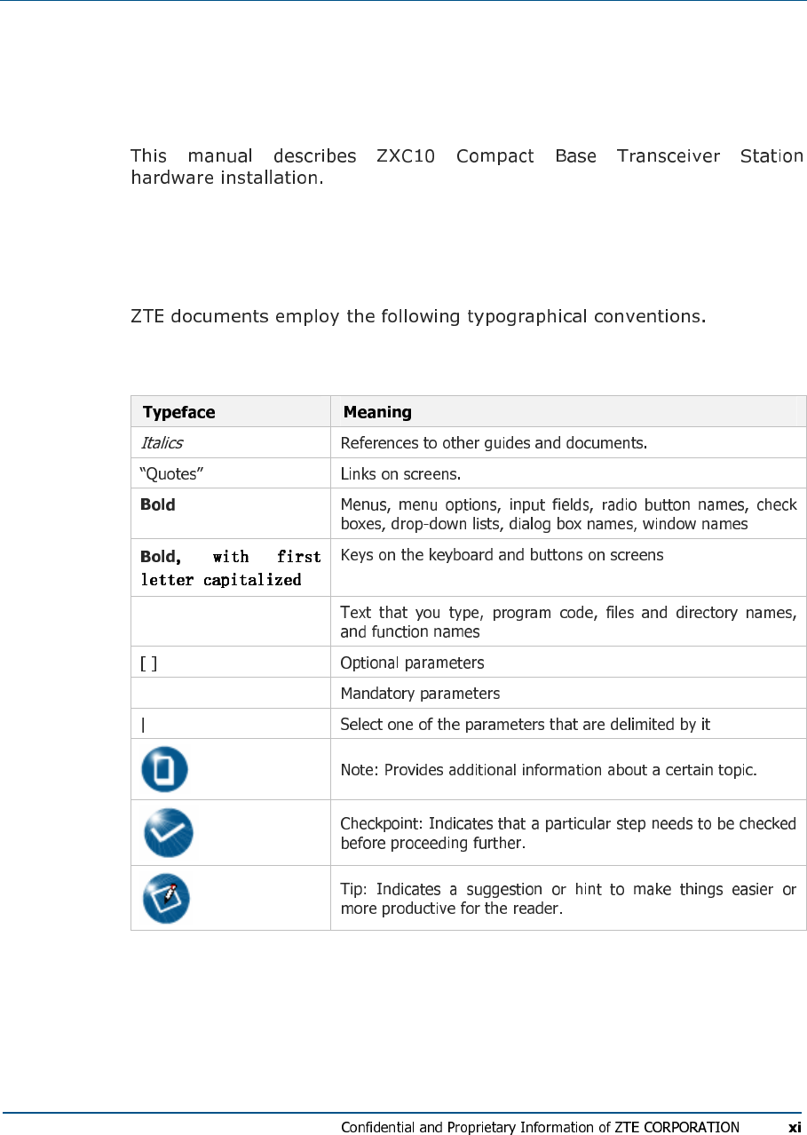
Purpose of this Manual
Typographical Conventions
TABL E 1 - TYP O G R A P H I C AL CO N V E N TI O NS
Constant width
{ }
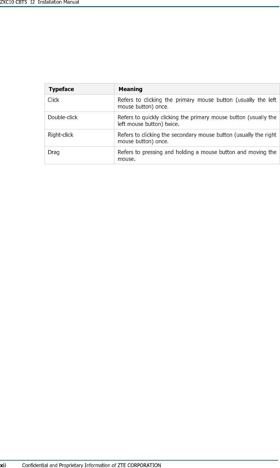
Mouse Operation Conventions
TABL E 2 - MOU S E OPE R A TI O N CO N VE N TI O N S
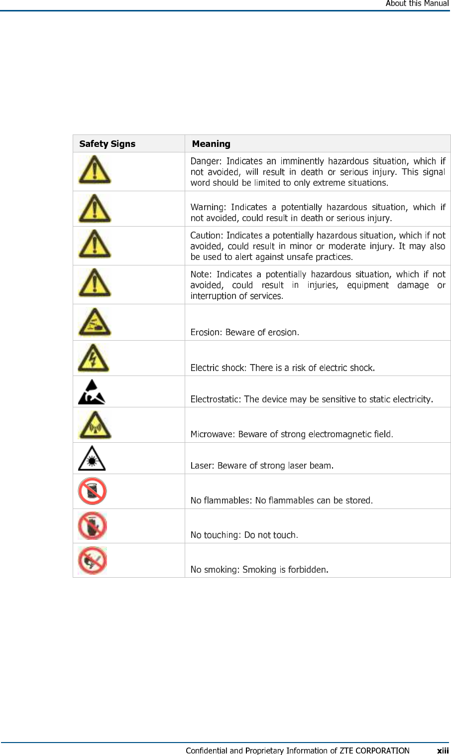
Safety Signs
TABL E 3 - SAF E T Y SI G N S
How to Get in Touch
Customer Support
Documentation Support
FCC STATEMENT
C h a p t e r 1
Installation Preparation
This chapter describes:
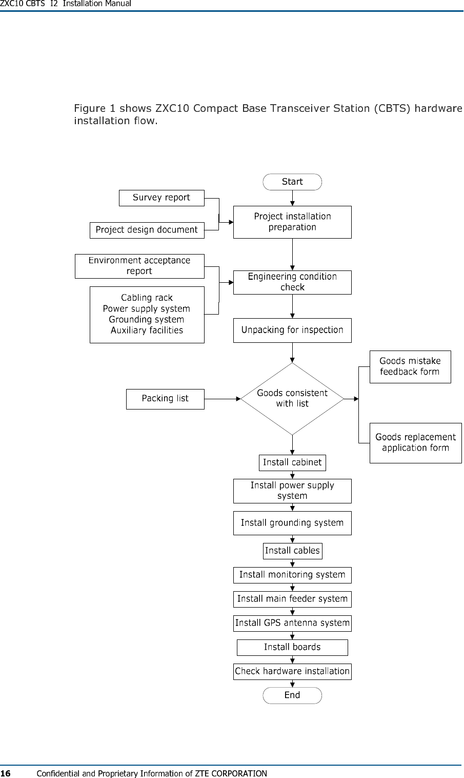
Hardware Installation Flow
FIG U R E 1 - HA R D W A R E INS T A L L AT I O N FL O W
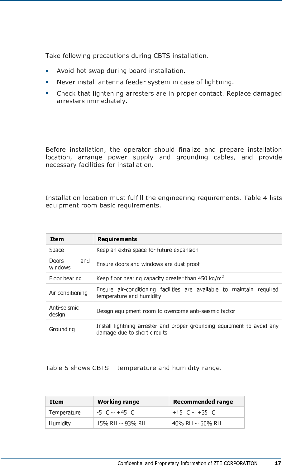
CBTS Installation Precautions
Environment Inspections
Installation Location Specifications
TABL E 4 - IN S T ALL AT I O N LO C ATI O N SP EC IF I C AT I ON S
Temperature and Humidity Range
TABL E 5 - TE M P E R ATU R E A N D HU M I D I T Y RAN G E
° ° ° °
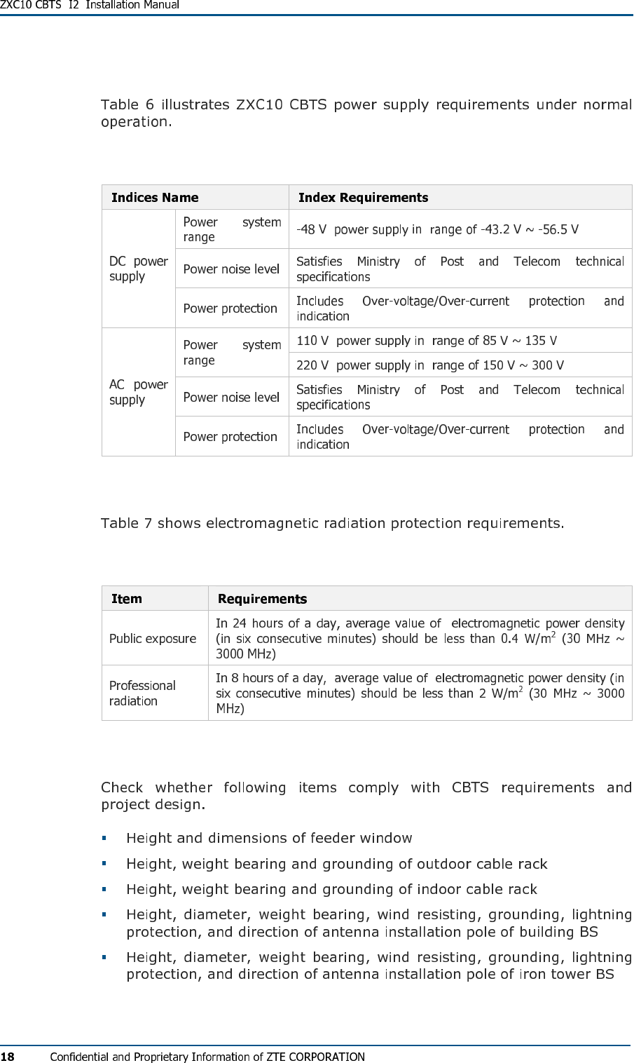
Power Supply Requirements
TABL E 6 - PO W E R SU PP L Y IND I C E S
Electromagnetic Radiation Protection
TABL E 7 - RAD I A T IO N PR O T E C TI ON RE Q U IR E M EN T S
Antenna Feeder System Requirements
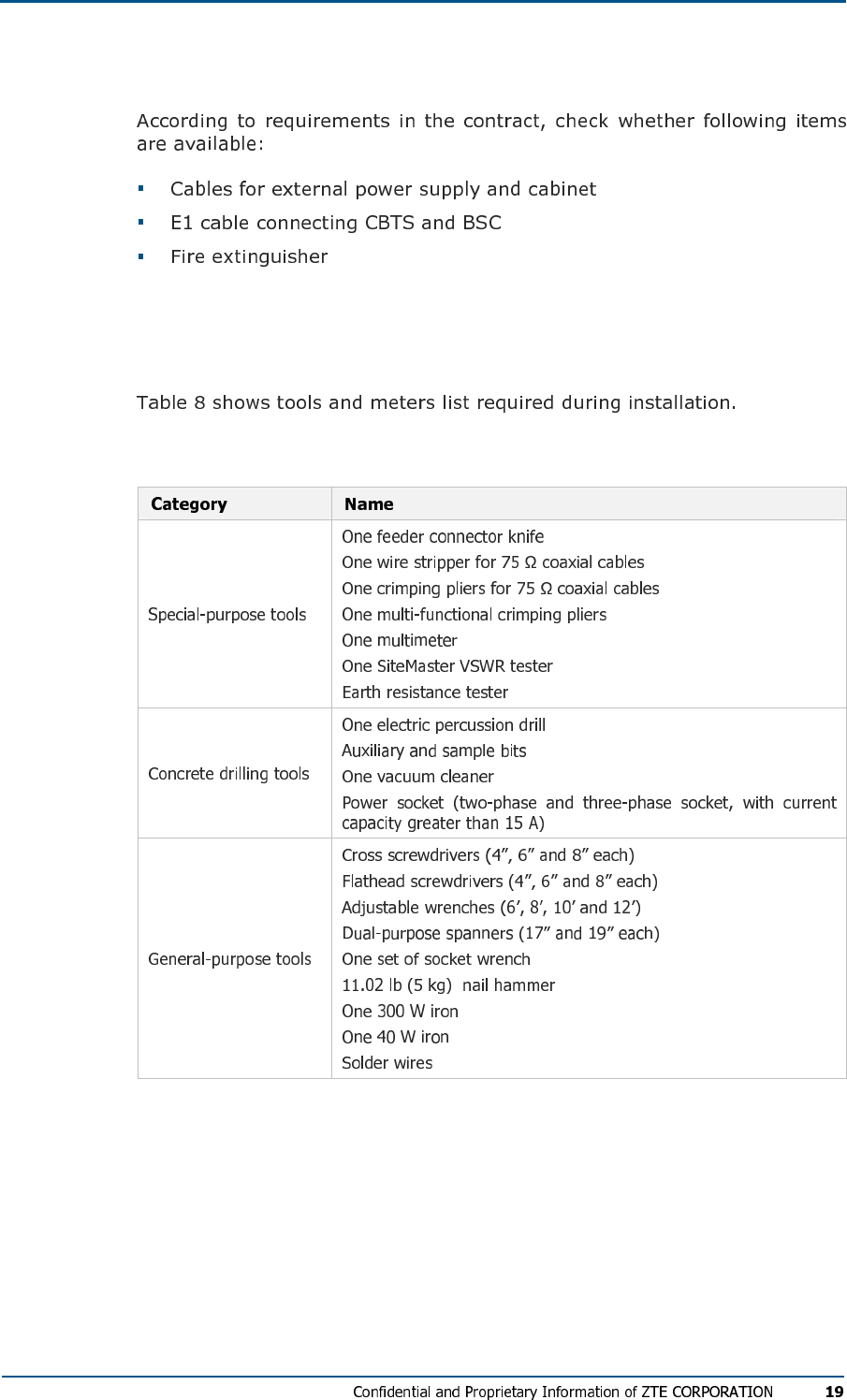
Other Accessory Devices
Tool and Meter List for Installation
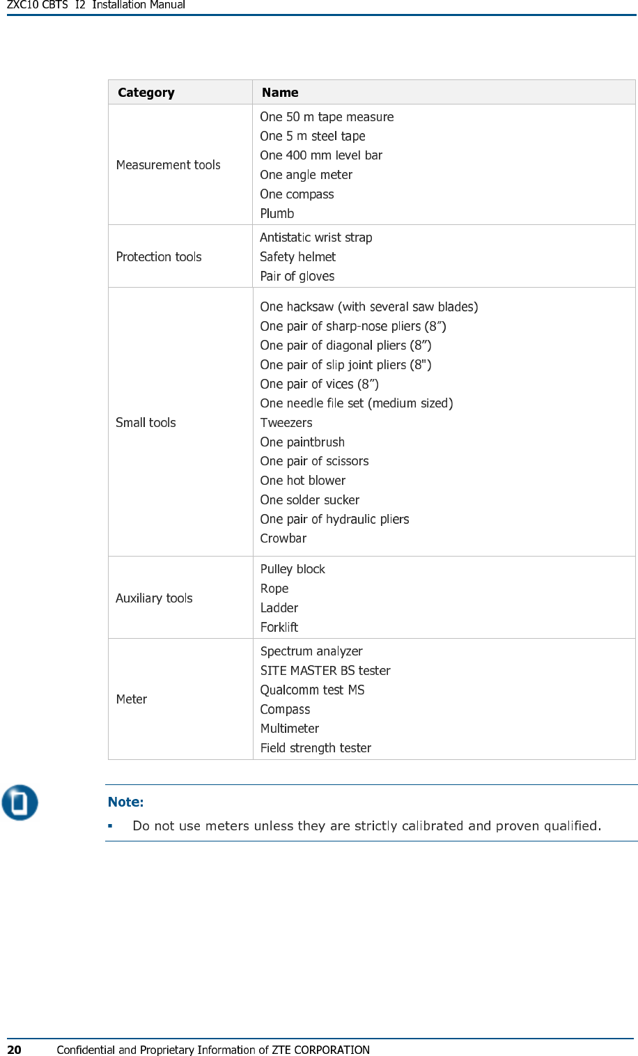
TABL E 8 - TO O L AN D MET E R LI S T
Technical Documentation
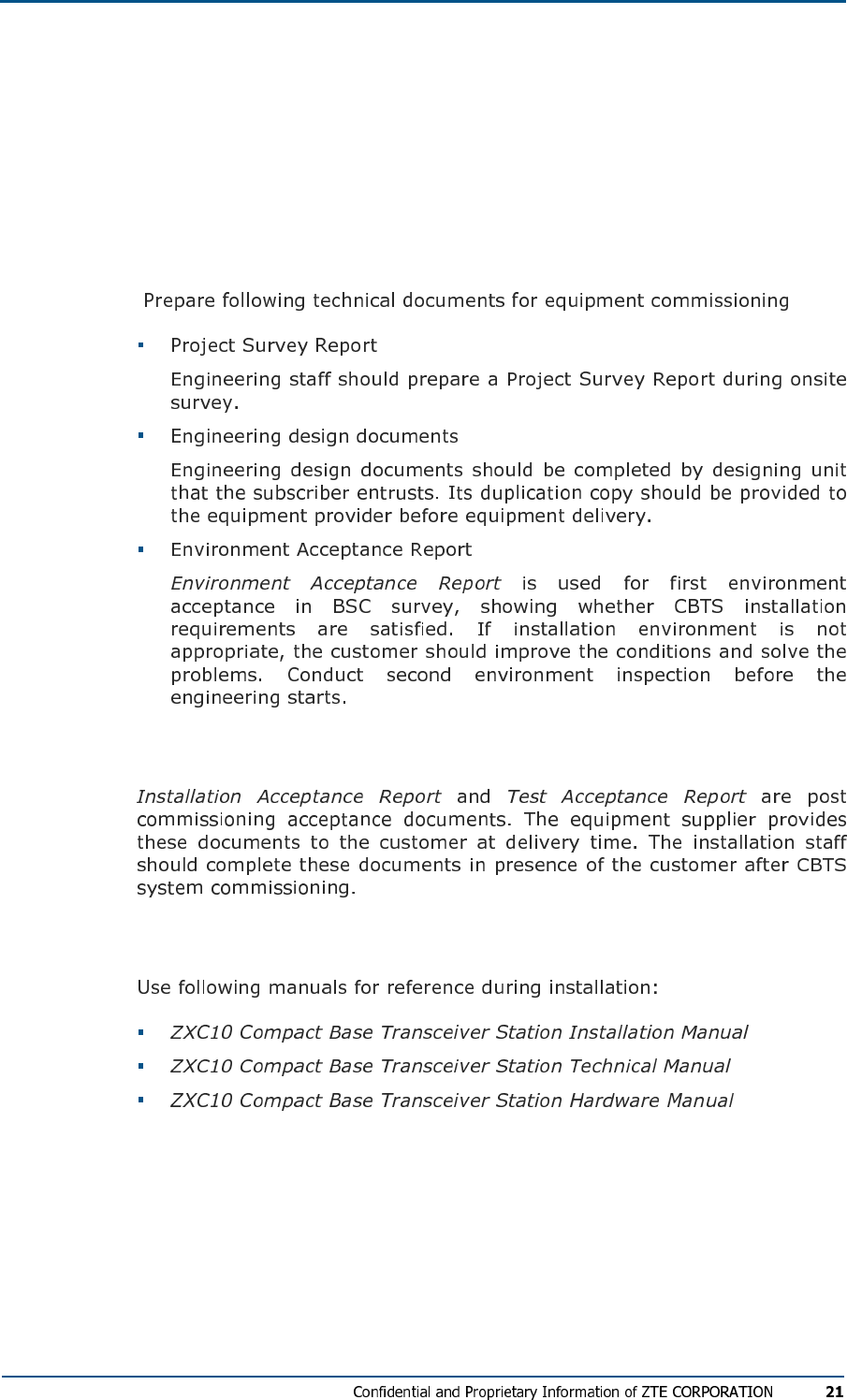
Preparation
Project Commissioning Documents
Acceptance Reports
Reference Documents

C h a p t e r 2
Unpacking and Handover
This chapter describes:
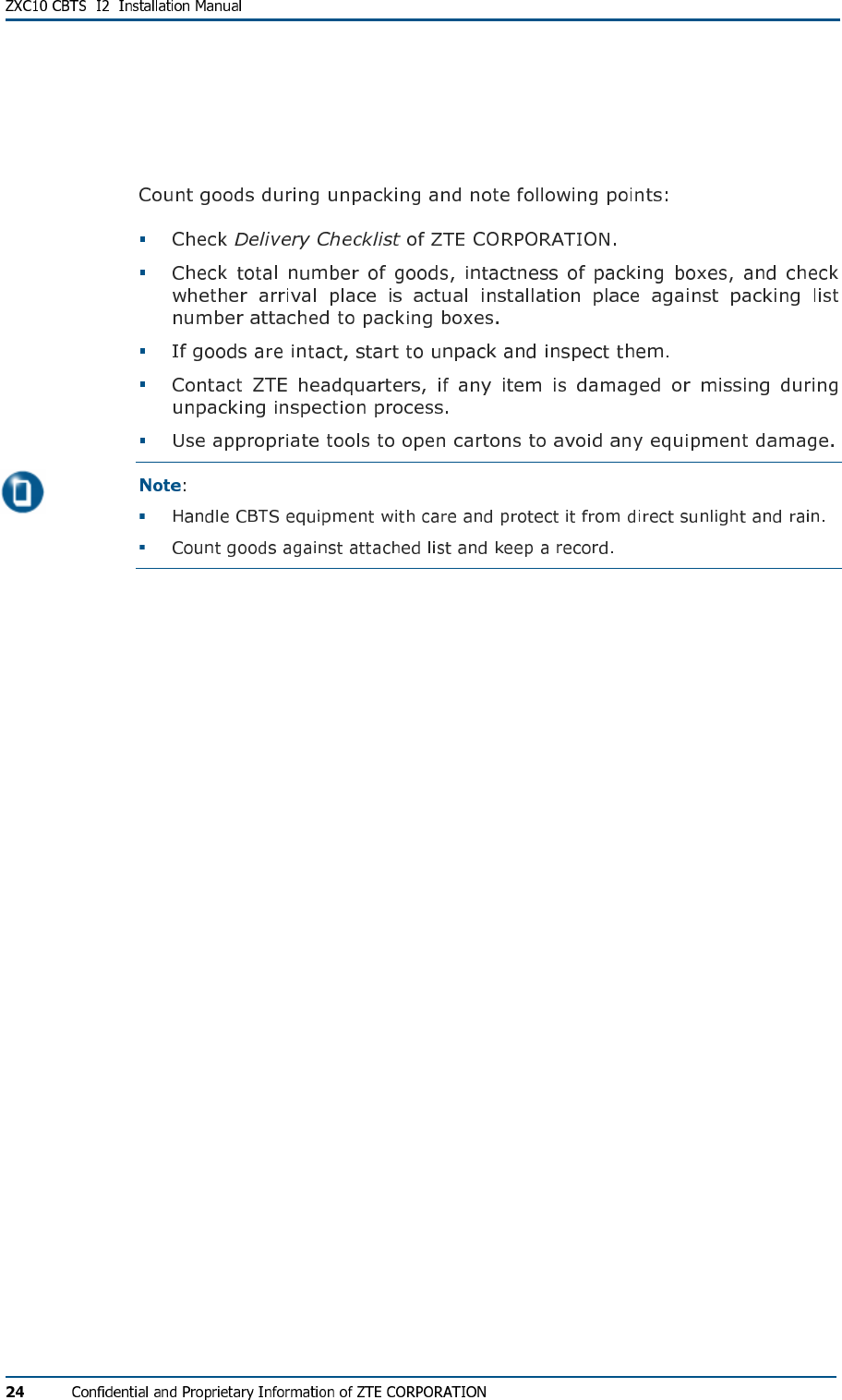
Checking Equipment List
Unpacking Wooden Box
Unpacking Procedure
Checking Cabinet
Unpacking Carton
Carton Structure
FIG U R E 2 - CA R T O N BO X
Unpacking Procedure
Unpacking Precautions
Checking Boards
Acceptance and Handover

C h a p t e r 3
Cabinet Installation
This chapter describes:
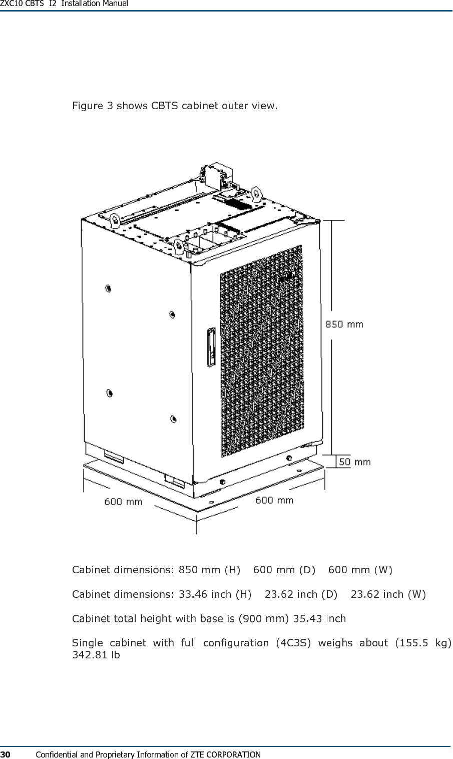
Cabinet Structure
FIG U R E 3 - CA B I NE T OU TE R VIE W
× ×
× ×
Cabinet Installation Precautions
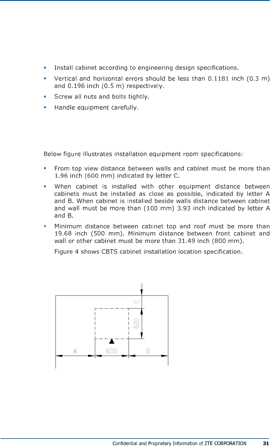
Installation Location Specification
FIG U R E 4 - IN S T AL L A TI ON LO C A T I O N SP E C I F IC A TI O N
Cabinet Installation Modes
Direct Installation Mode
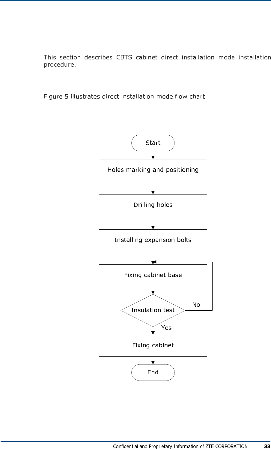
Direct Installation Mode Flow
FIG U R E 5 - DI R E C T IN S T AL L A T I O N MOD E FL O W CH A R T
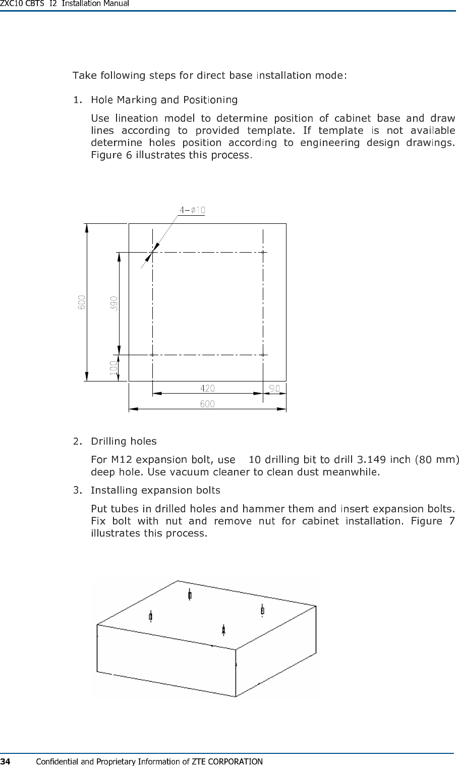
Direct Installation Mode Procedure
FIG U R E 6 - HO L E S PO S I T IO N IN DI RE CT INS T ALL AT IO N MODE (UN I T S M M)
φ
FIG U R E 7 - EX P AN S IO N BO L T S IN S T A L L AT I O N
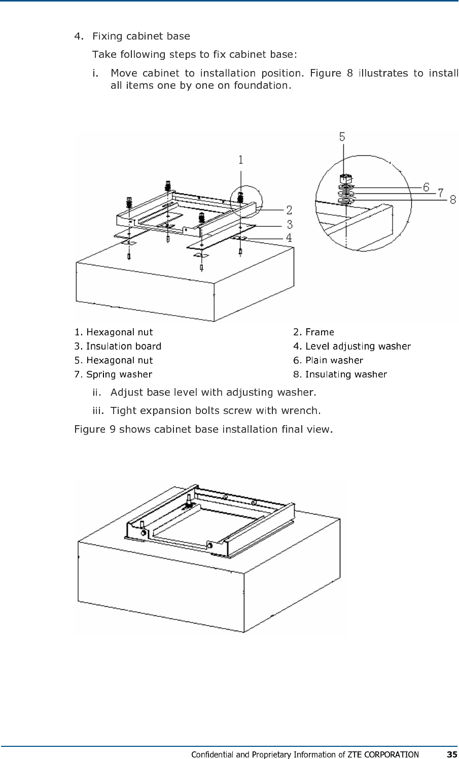
FIG U R E 8 - CA B I NE T BA S E FI XI N G
FIG U R E 9 - CA B I NE T BA S E IN S T AL L AT IO N
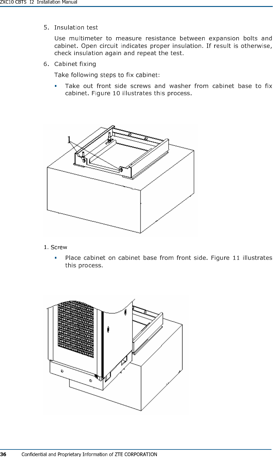
FIG U R E 10 - UN IN ST AL LI NG SCR EW S AN D WA S HE R S
FIG U R E 11 - PL AC IN G CABI NE T ON BASE
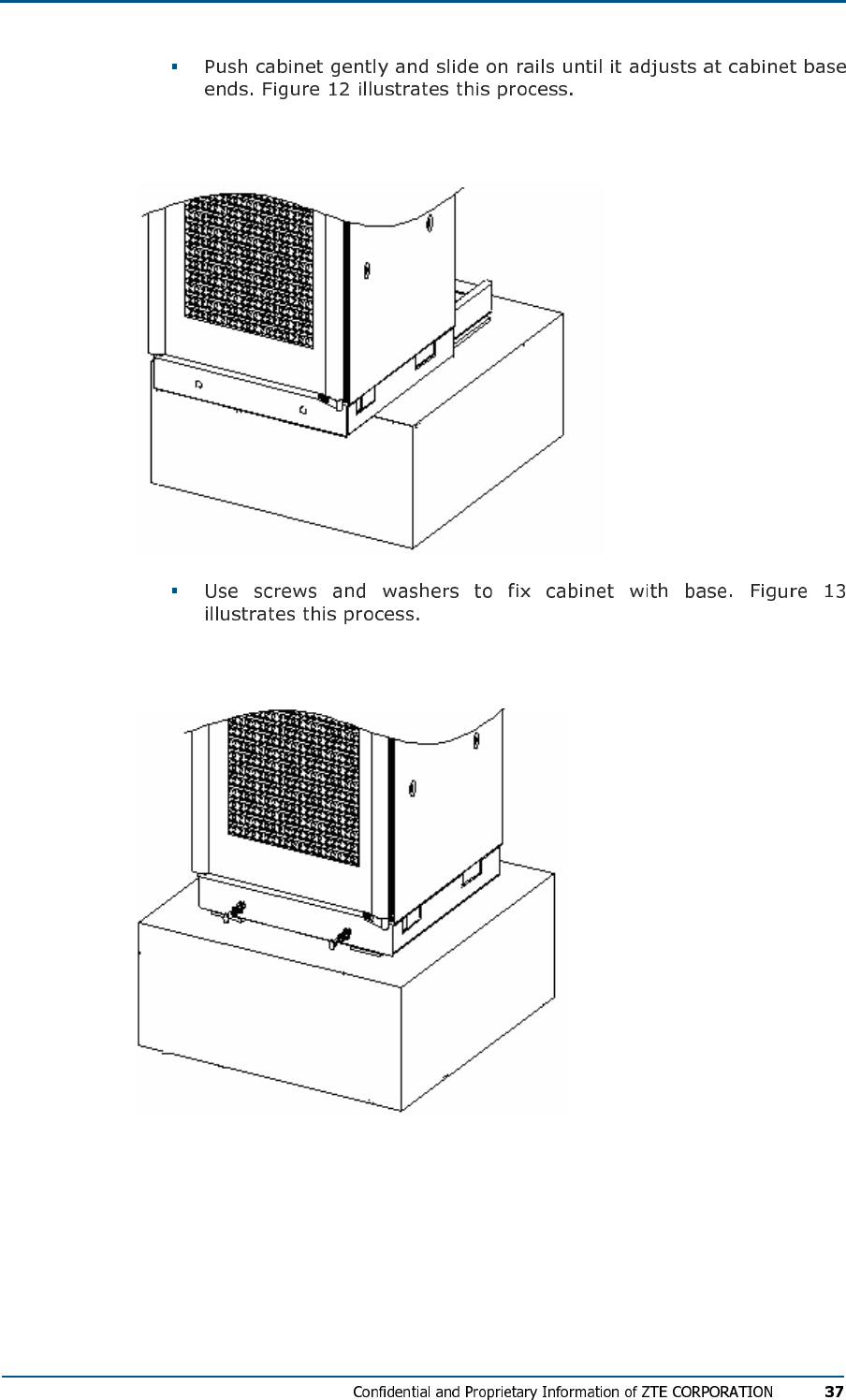
FIG U R E 12 - AD J US TIN G CAB IN ET ON BA S E
FIG U R E 13 - FI XI NG CAB I NE T AND BAS E
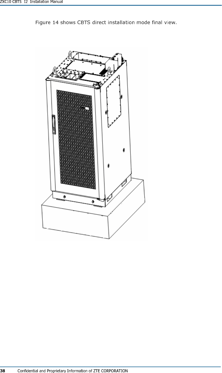
FIG U R E 14 - DI RE CT IN ST AL LAT IO N MODE FI N AL VI E W
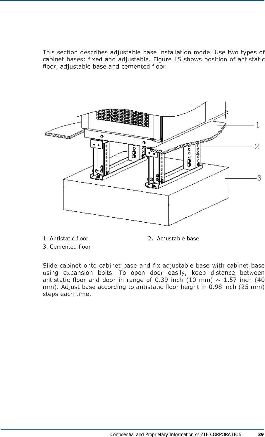
Adjustable Base Installation Mode
FIG U R E 15 - AD J US TAB LE BAS E IN ST ALL AT IO N MODE
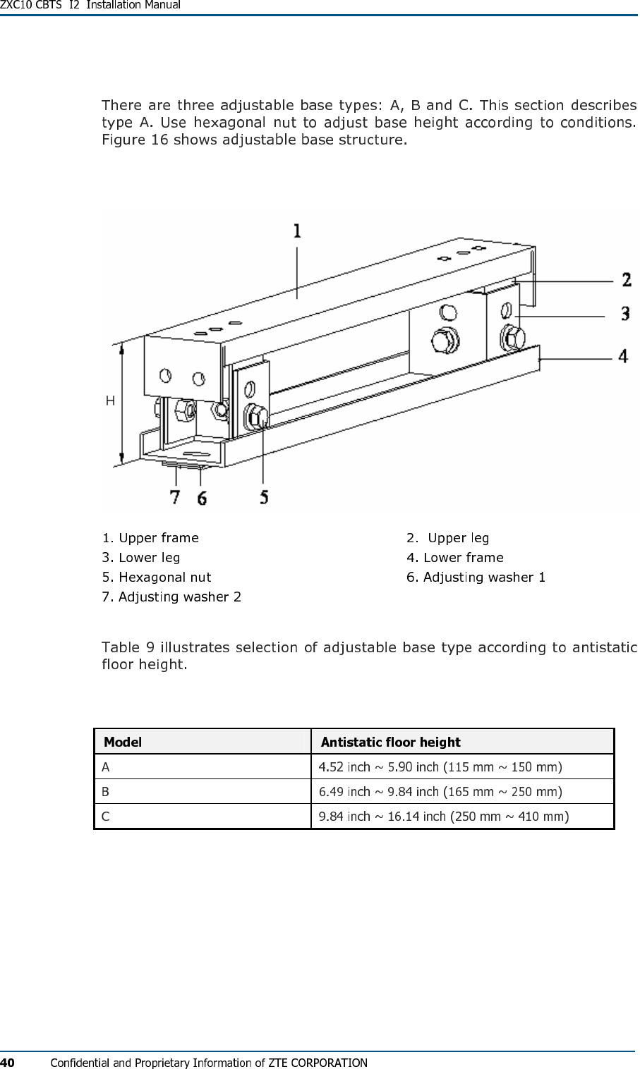
Adjustable Base Structure
FIG U R E 16 - AD J US TAB LE BA S E
TABL E 9 - AD J U S T AB L E BAS E SE L E C TI O N
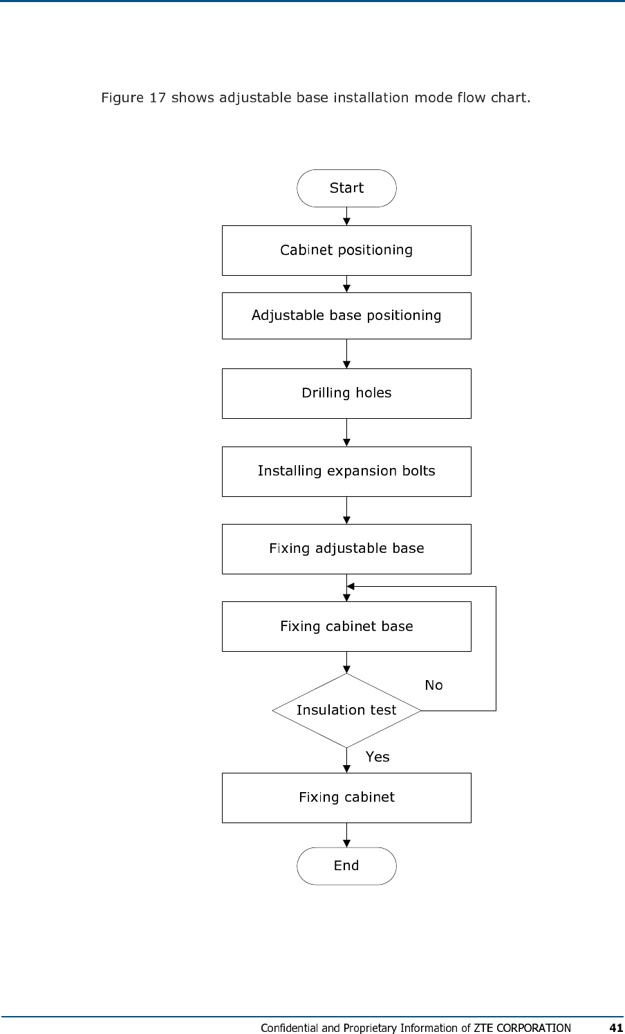
Adjustable Base Installation Mode Flow
FIG U R E 17 - AD J US TAB LE BAS E IN ST ALL AT IO N MODE FL OW CH A R T
Adjustable Base Installation Procedure
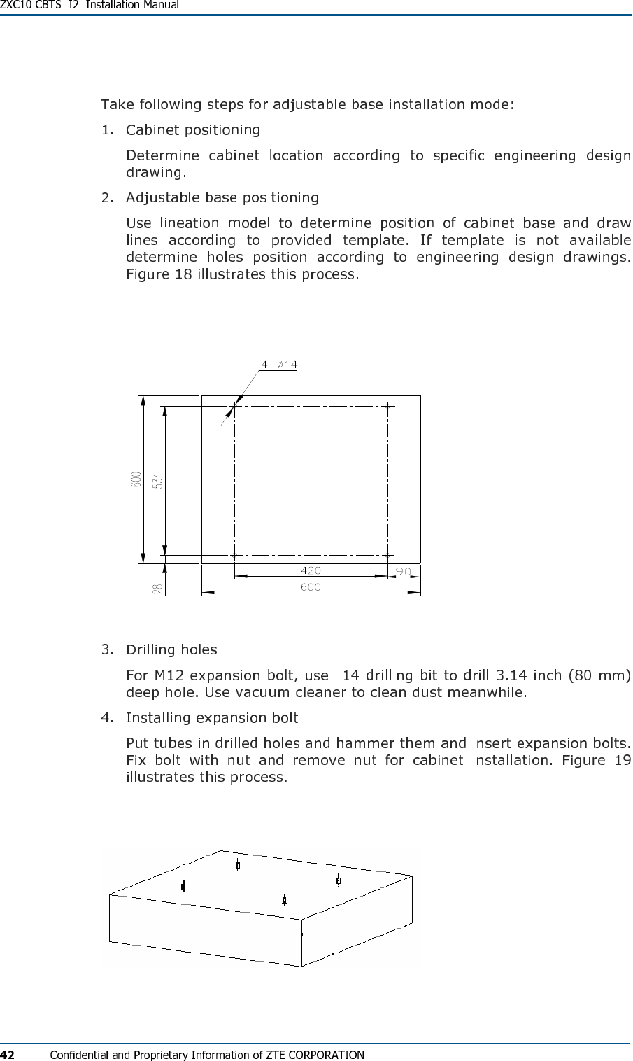
FIG U R E 18 - HO LE S PO SI TI ON I N AD JU ST AB L E BAS E IN S T A L L AT I O N MO DE (UNI TS M M)
φ
FIG U R E 19 - EX P ANS IO N BOL TS IN S T AL L A TI O N
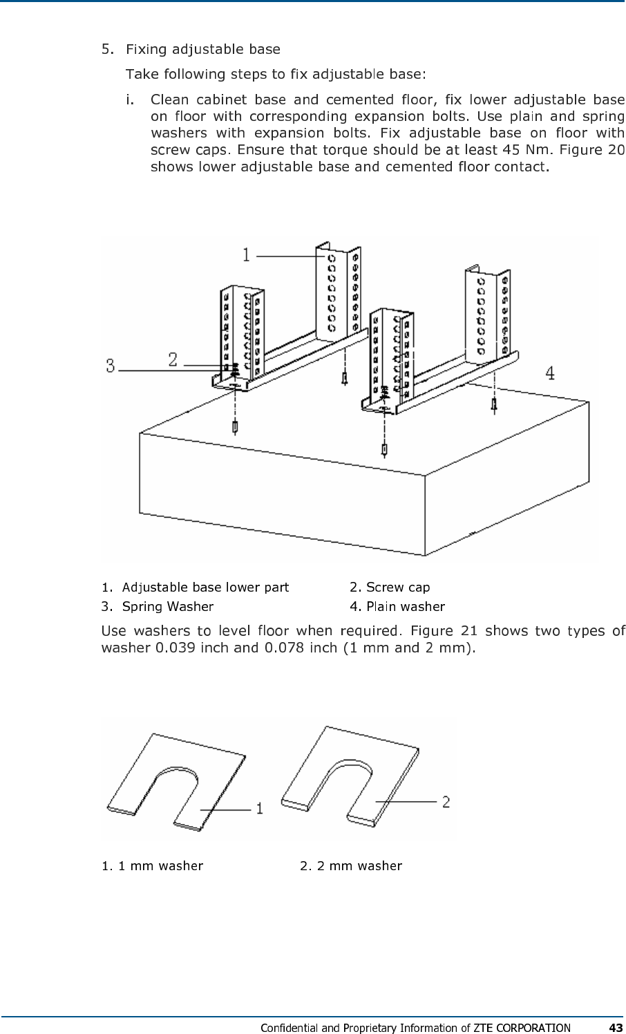
FIG U R E 20 - LO WE R AD J US TAB L E BASE AND CE ME N TED FL O O R
FIG U R E 21 - WASH ER S SP E C IF I C AT IO N S
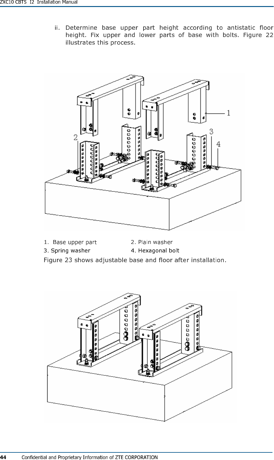
FIG U R E 22 - BAS E UPP ER PAR T IN S T AL L A TI O N
FIG U R E 23 - AD J US TAB LE BAS E AN D FLO OR IN S TAL L ATI ON FIN AL VI E W
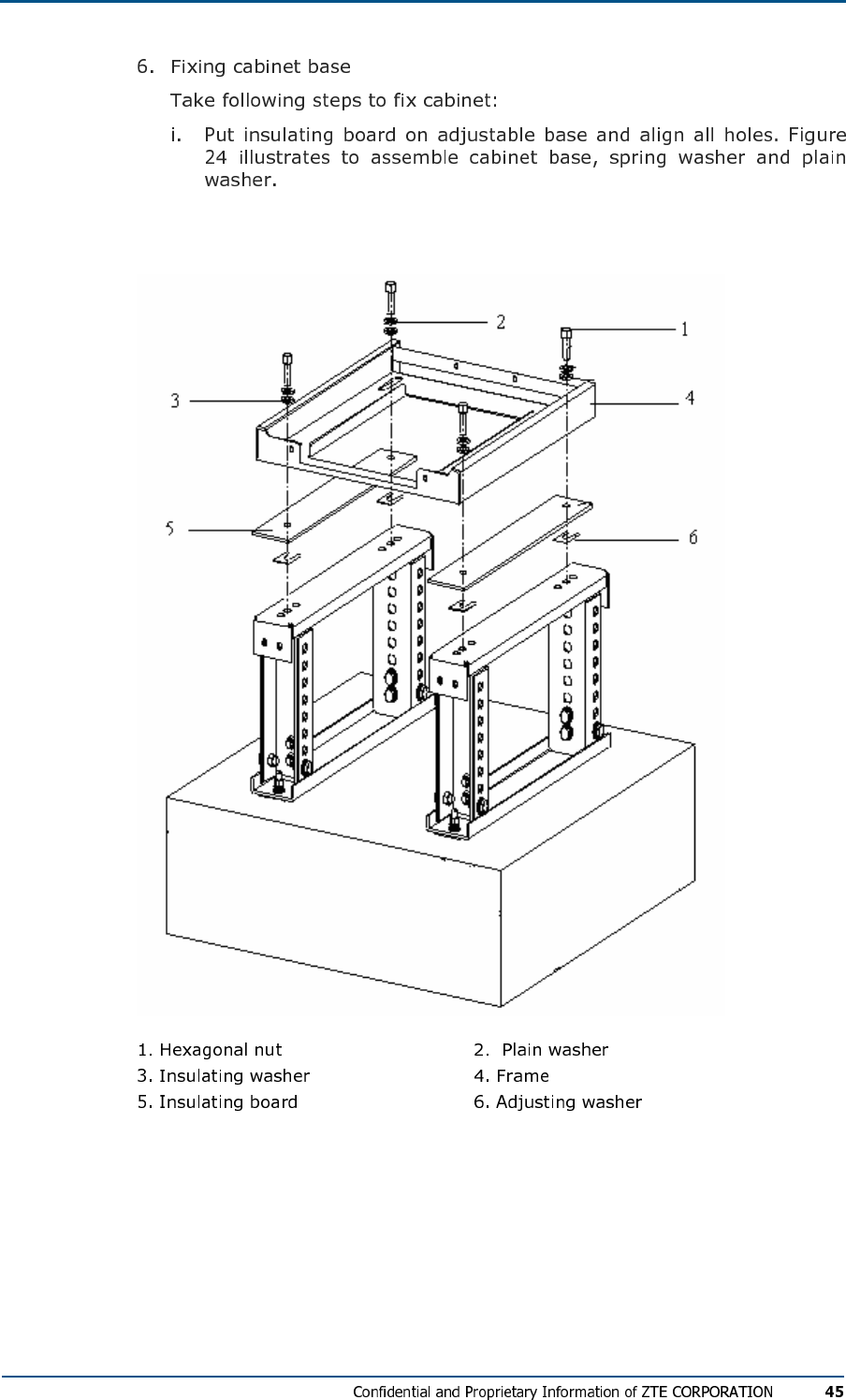
FIG U R E 24 - FI XI NG CAB I NE T BA S E
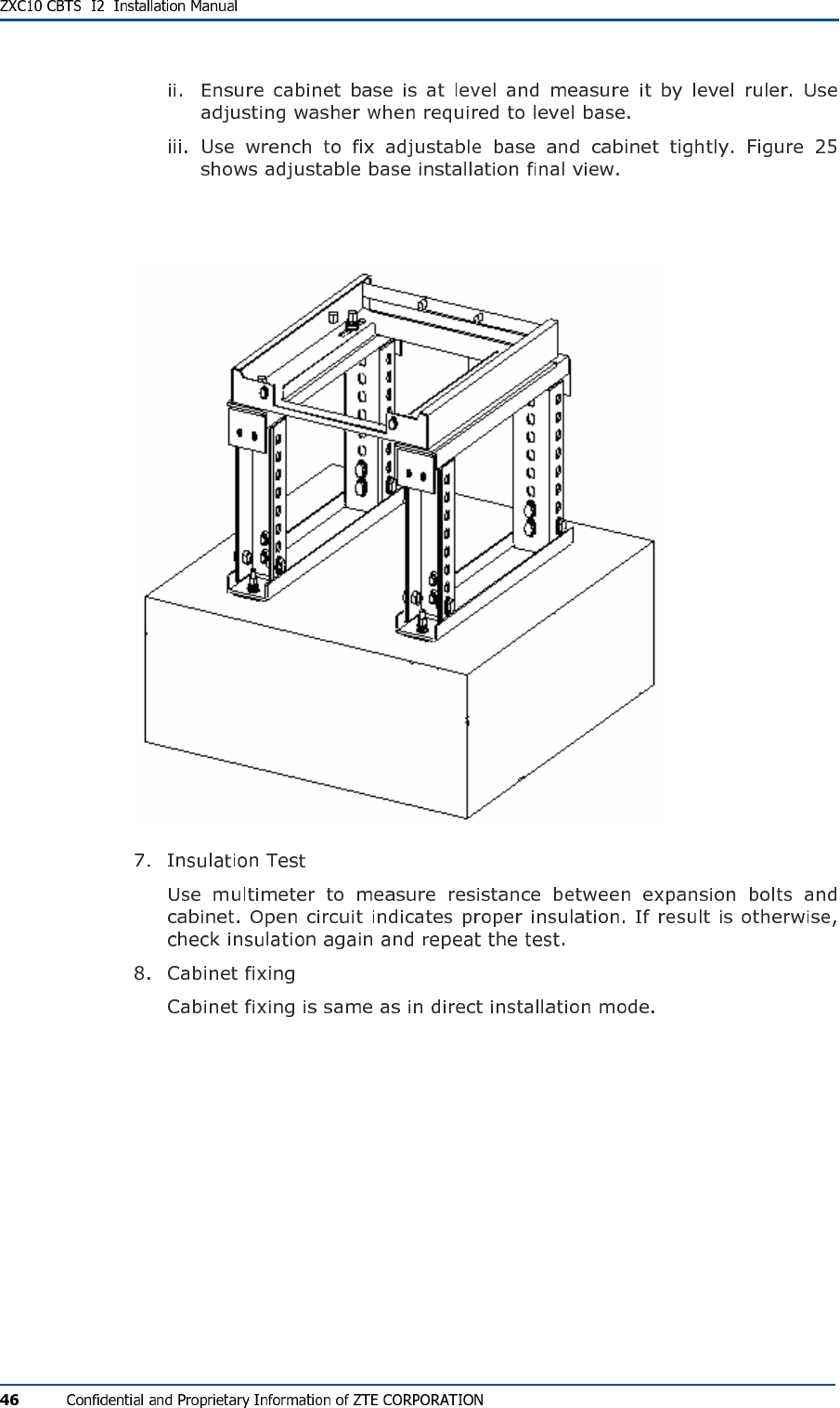
FIG U R E 25 - AD J US TAB LE BAS E I NS TAL L ATI ON FIN AL VI E W
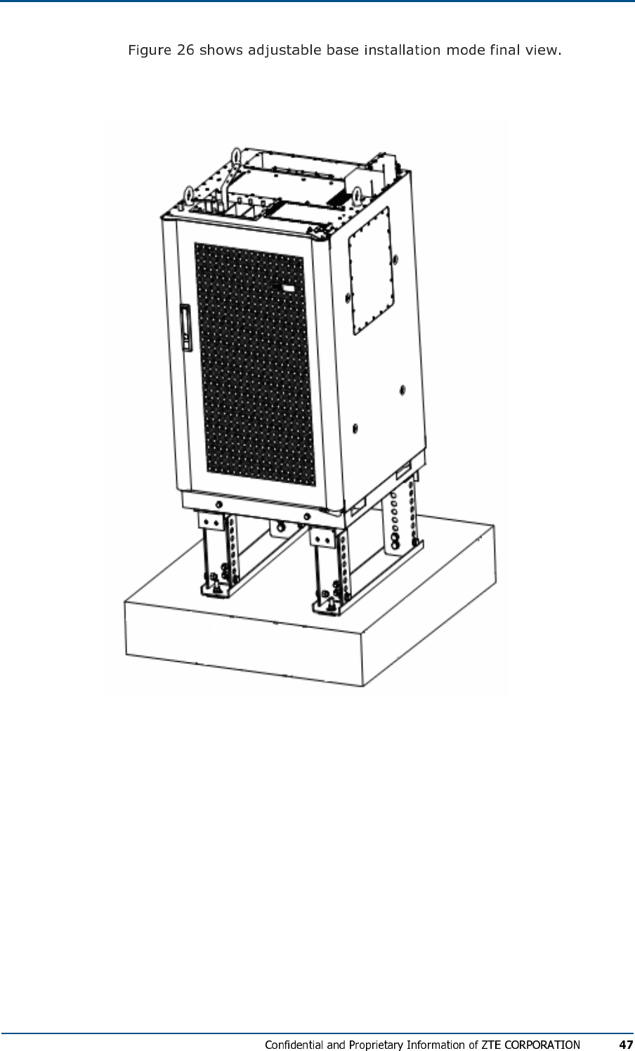
FIG U R E 26 - AD J US TAB LE BAS E IN ST ALL AT IO N MODE FI N A L VI E W
Cabinet Accessories Installation
Cabling Runway
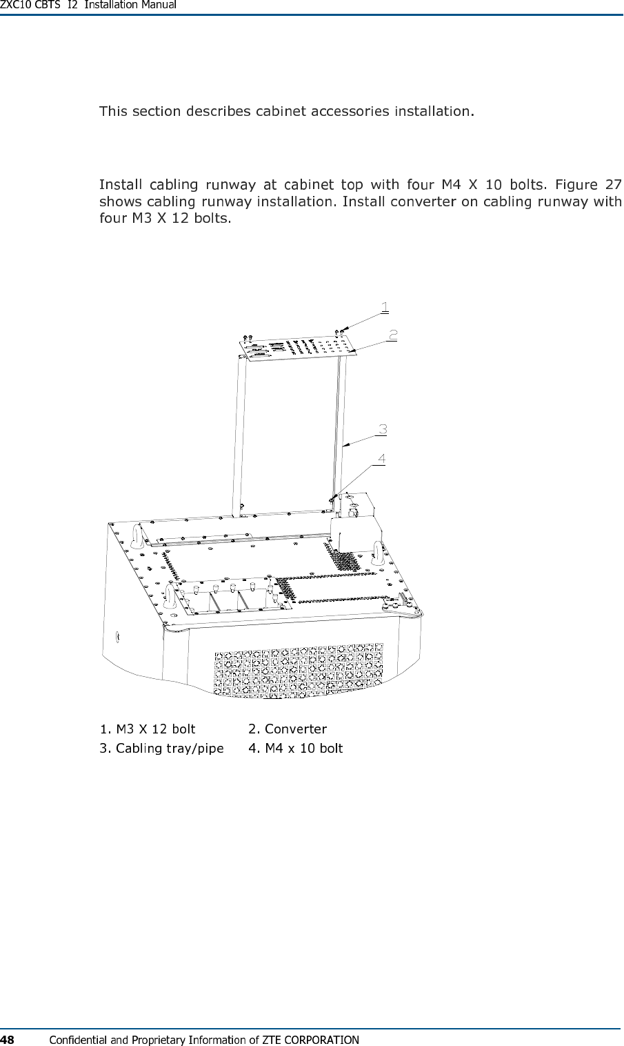
FIG U R E 27 - CAB LI NG RU N W A Y
CBTS Cabinet Interfaces
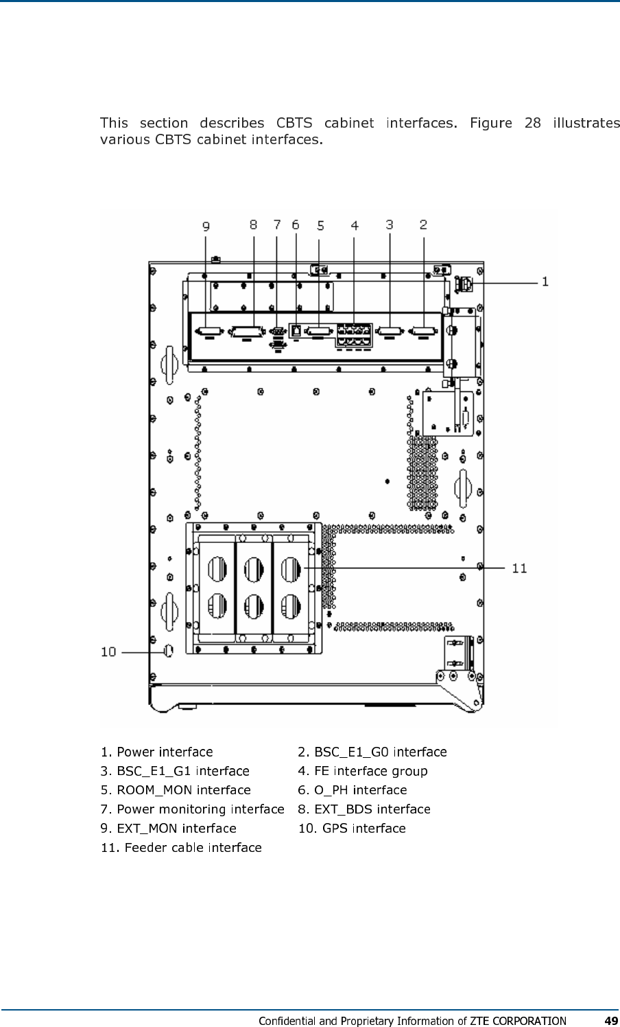
FIG U R E 28 - CBTS CAB I N E T IN T ER F AC E S
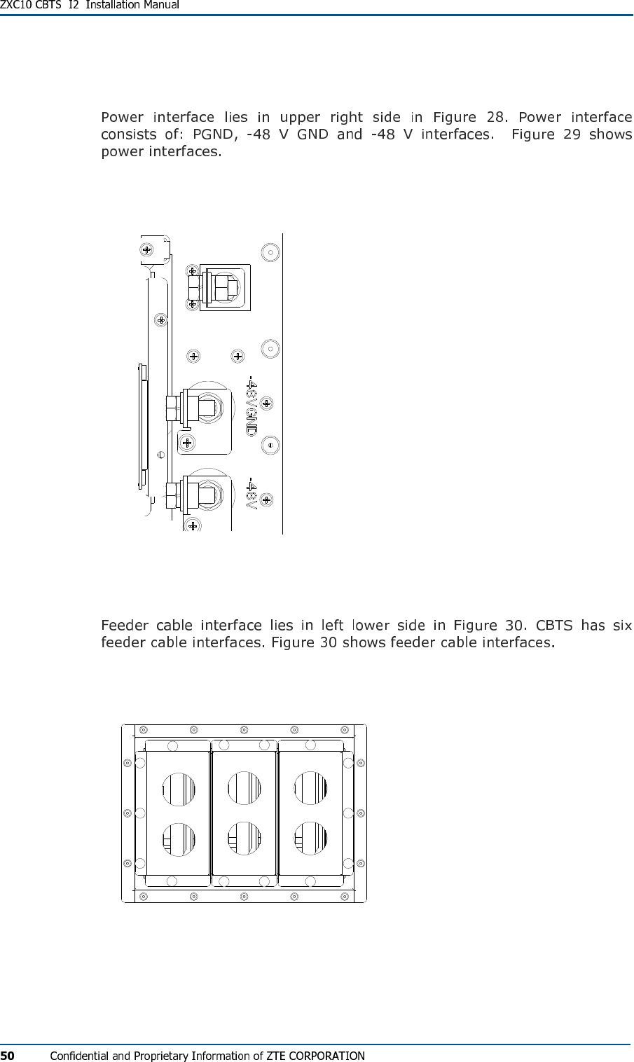
Power Interface
FIG U R E 29 - PO WE R IN T E RF AC E S
Feeder Cable Interface
FIG U R E 30 - FE ED ER CAB L E IN TE R F AC E
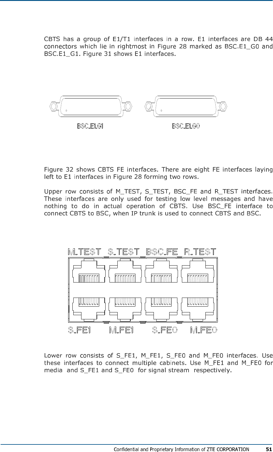
E1/T1 Interfaces
FIG U R E 31 - CBTS E1 IN T E R F AC E S
FE Interfaces
FIG U R E 32 - CBTS FE IN TE R F AC E S
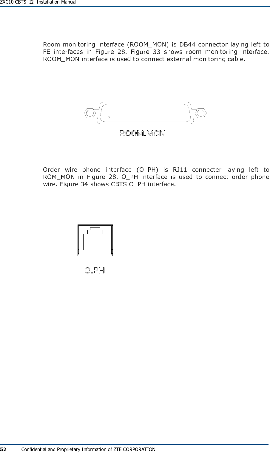
Room Monitoring Interface
FIG U R E 33 - CBTS ROO M MO NI TO RI N G IN T ER F AC E
Order Wire Phone Interface
FIG U R E 34 - CBTS ORD WE R WIR E PH O N E IN T E R F A CE
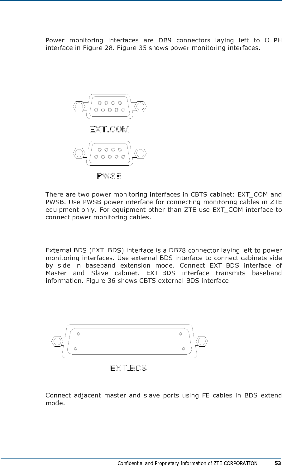
Power Monitoring Interface
FIG U R E 35 - PO WE R MONI TO RI NG IN T E R F AC E S
External BDS Interface
FIG U R E 36 - CBTS EX T E R N AL BDS IN T E R F AC E
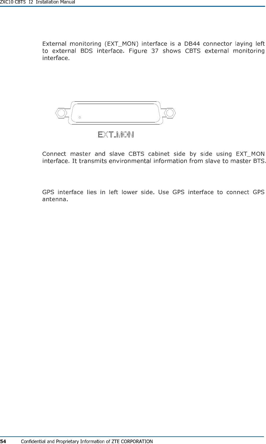
External Monitoring Interface
FIG U R E 37 - CBTS EX T E R N AL MON I T O R I N G IN T E R F A CE
GPS Interface
C h a p t e r 4
Cable Installation
This chapter describes cable installation:
Power and Grounding Cables
Power Cable Types
Power Cable Preparation
FIG U R E 38 - CR IM PI NG PL I E R S
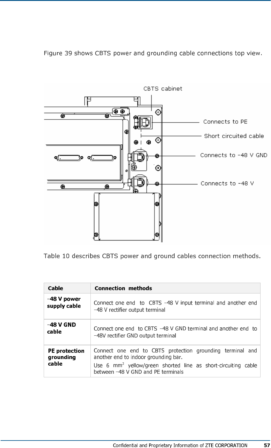
Power and Grounding Cable Connections
FIG U R E 39 - CBTS PO W E R AN D GR O U N D I N G CA B L E CO N N EC T I ON
TABL E 10 - PO WE R AN D GR OU ND IN G CABL E CON NE CTI ON
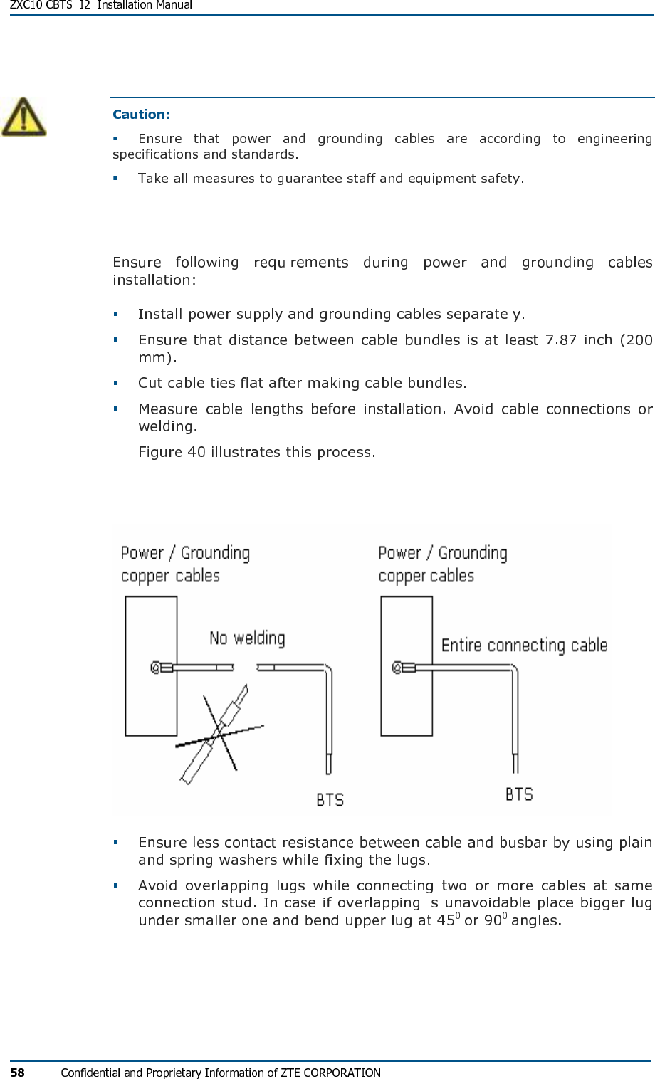
Cable Installation Requirements
FIG U R E 40 - PO WE R SUP PL Y AN D GR OU ND IN G CAB L E S
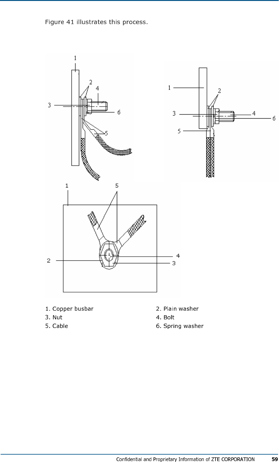
FIG U R E 41 - PO WE R SUP PL Y CABL E CO N N E C TI O NS
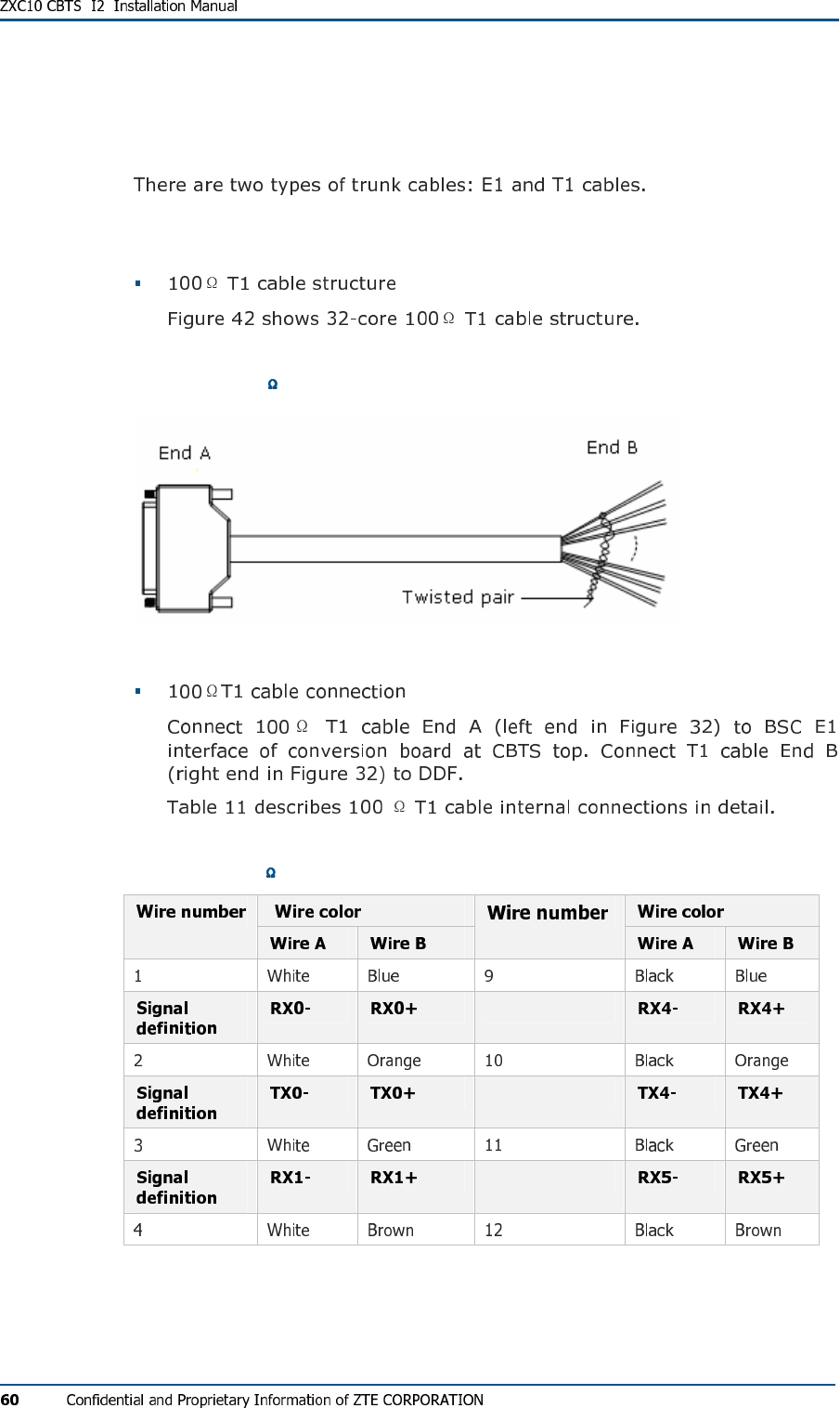
Trunk Cable Installation
T1 Cable Installation
FIG U R E 42 - 100 T1 CABL E STR U C TU R E
TABL E 11 - 100 IN TE R N AL CAB L E CO N N E C TI O NS
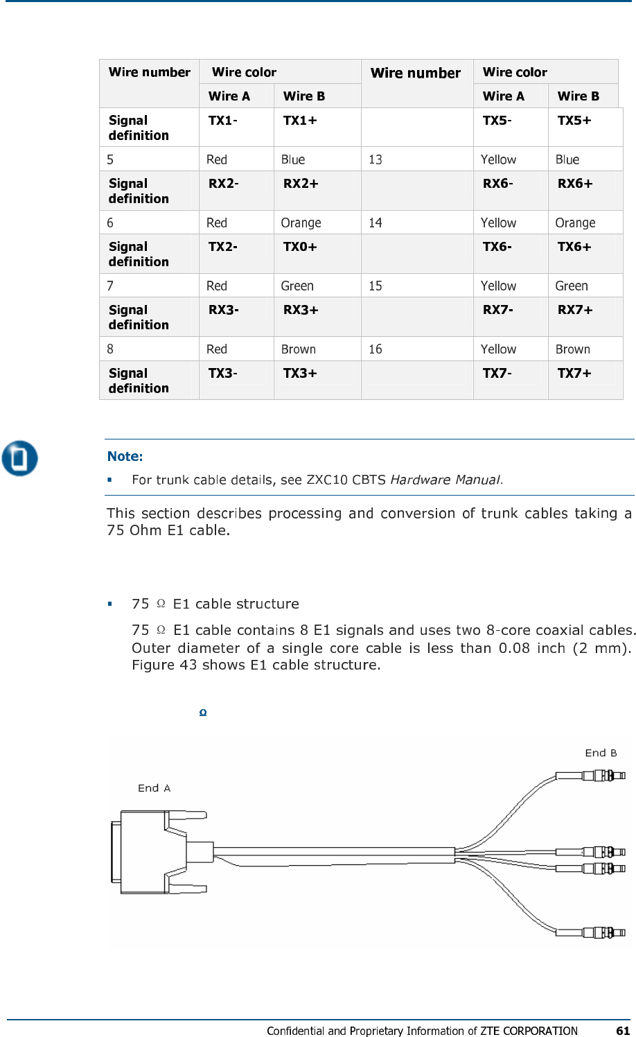
E1 Cable Installation
FIG U R E 43 - 75 E1 CABL E STR U C TU R E
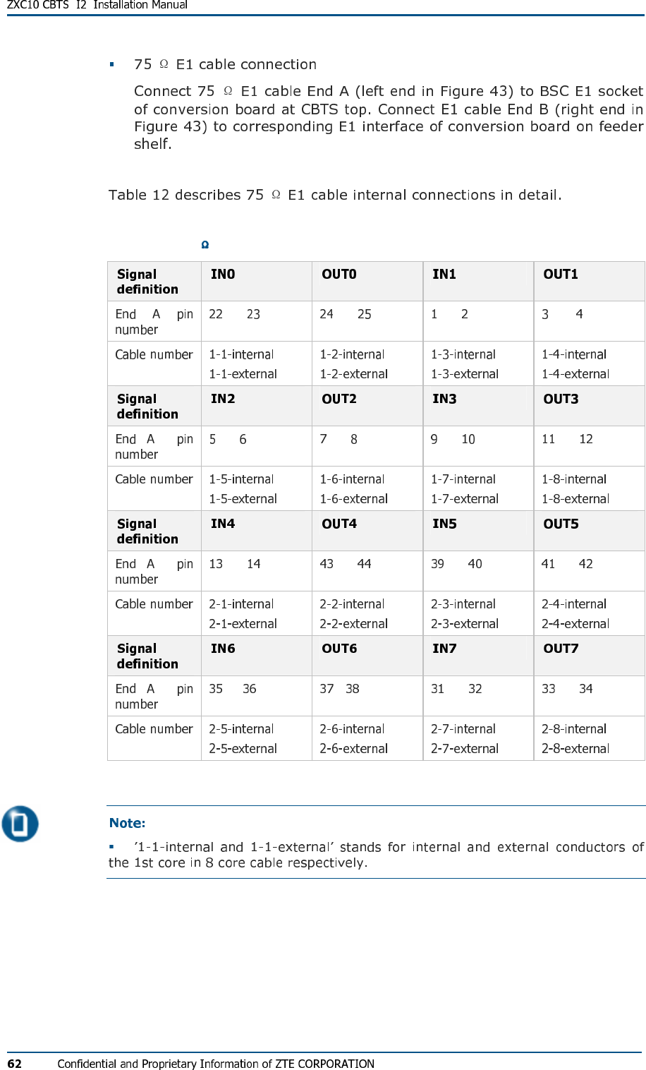
TABL E 12 - 75 E1 CABL E IN TER N AL CO N N EC T IO N S
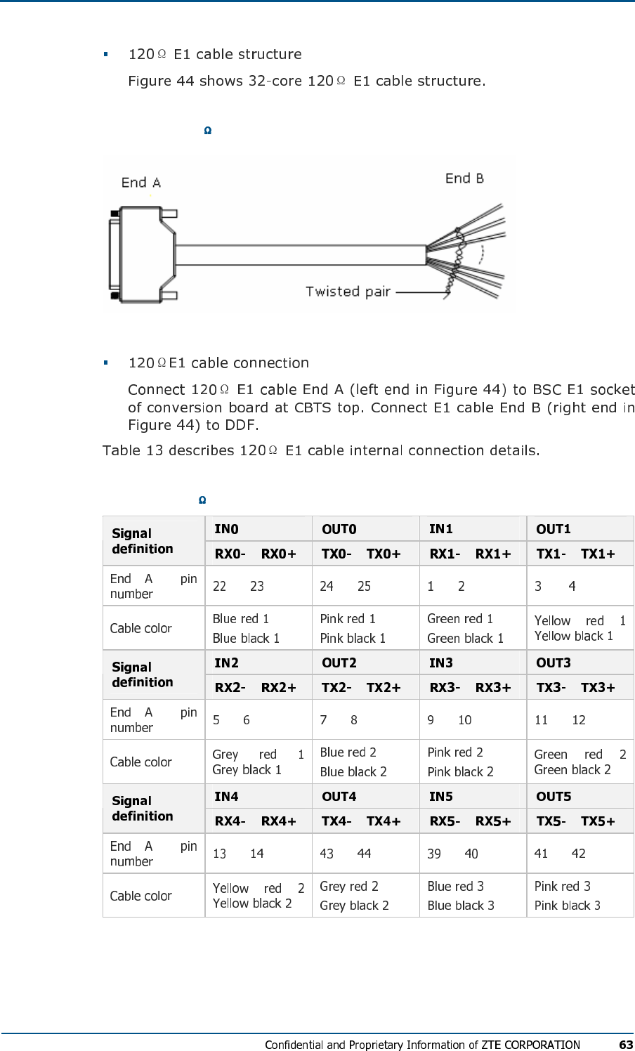
FIG U R E 44 - 120 E1 CAB L E ST RU C TU R E
TABL E 13 - 120 E1 CAB L E IN T ER N A L CO N N E C TI O N S
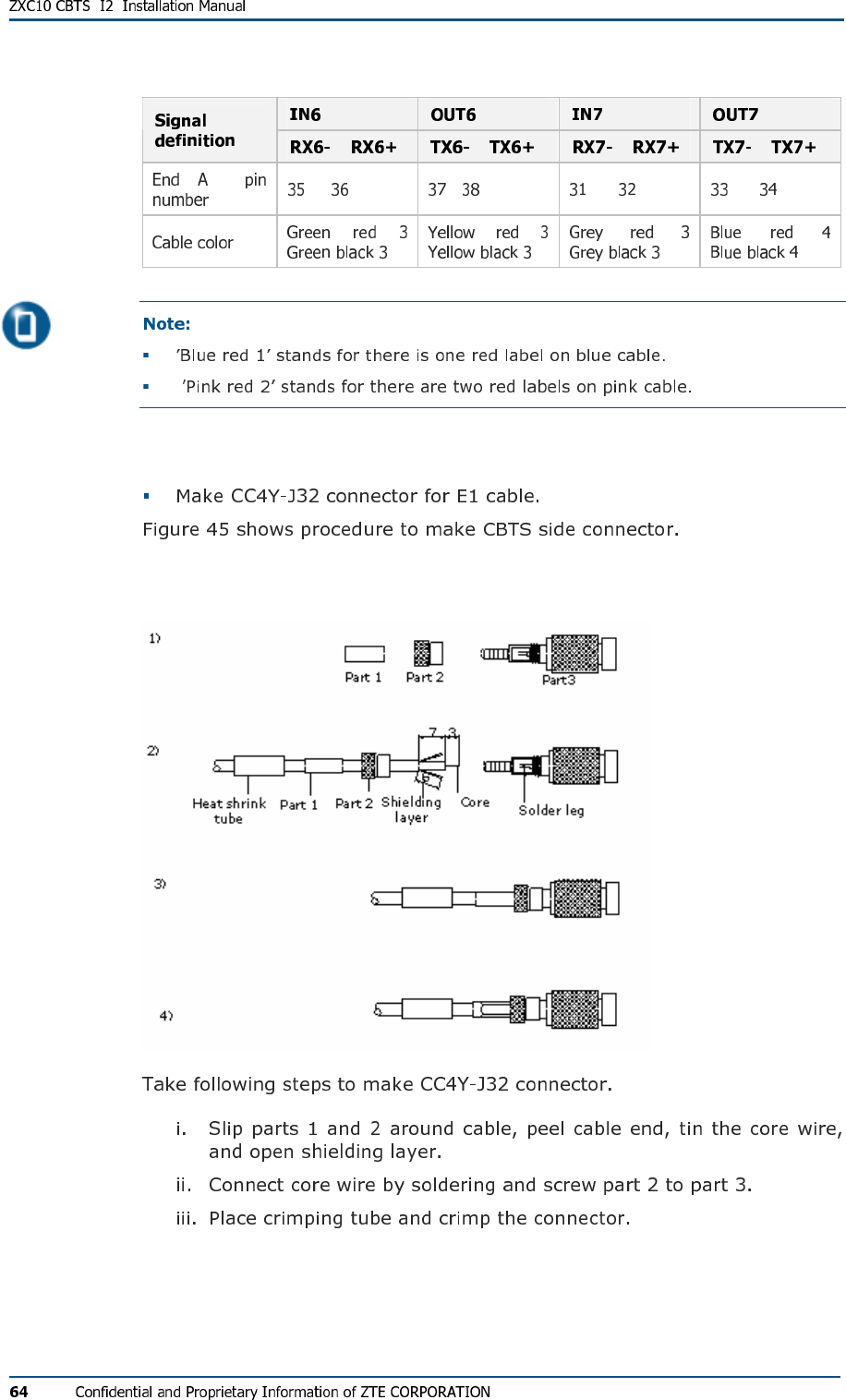
Trunk Cable Processing
FIG U R E 45 - CC4Y-J3 2 CO A XI AL CAB LE CON NE C TOR AS S E M BL Y
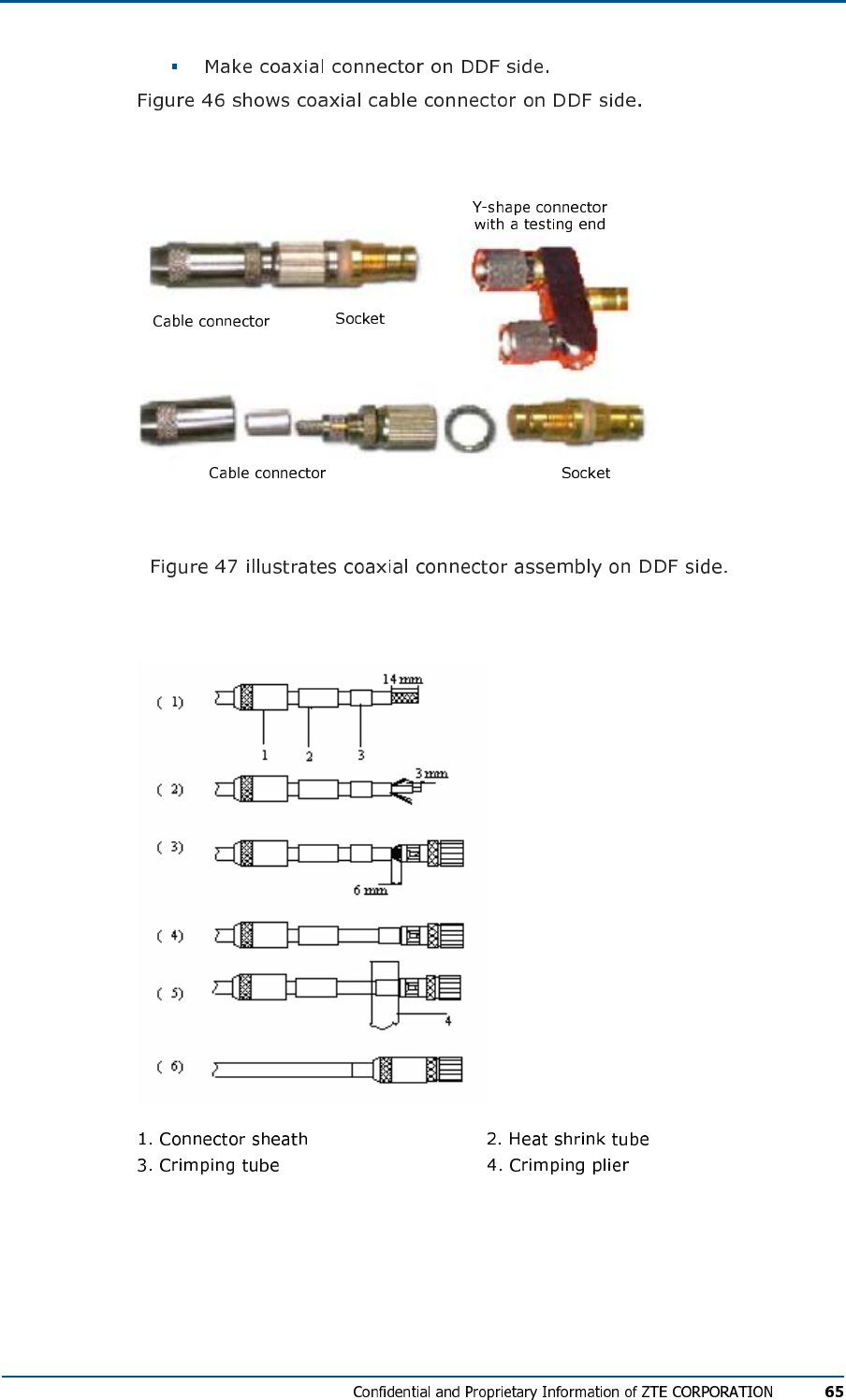
FIG U R E 46 - CO AX I AL CABL E ON DDF SI D E
FIG U R E 47 - CO AX I AL CON NE CT OR ASS EM BL Y ON DDF SI DE
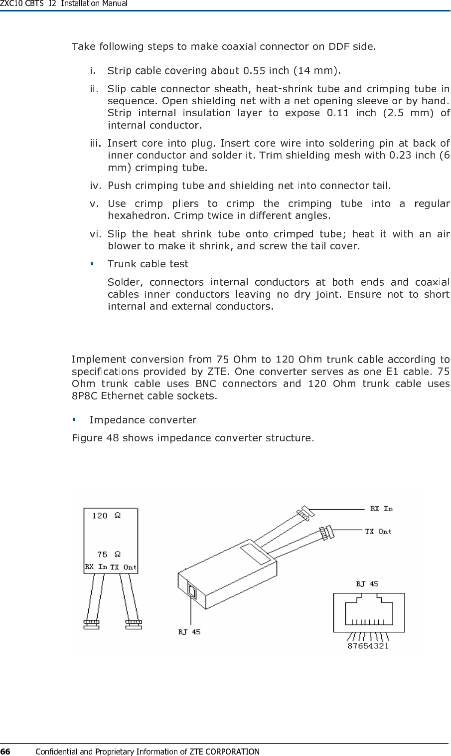
Trunk Cable Conversion
FIG U R E 48 - IM PE D ANC E CO N VE R T ER
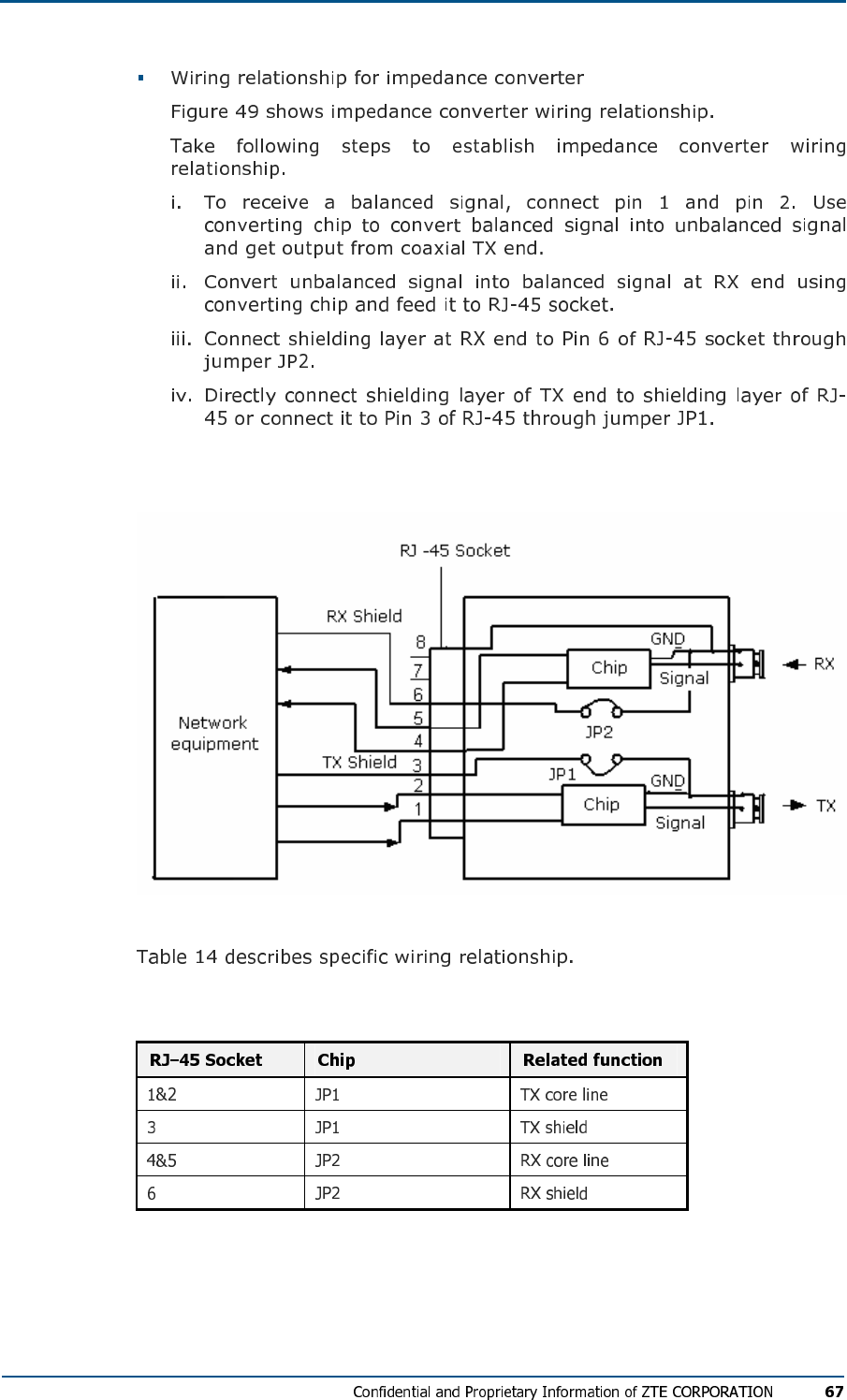
FIG U R E 49 - IM PE D ANC E CON VE RT ER WIR ING RE L A TI O N SH I P
TABL E 14 - IM PE D ANC E CON VE RT ER WIR IN G R EL AT IO N S H I P
E1/T1 Cable Installation Requirements
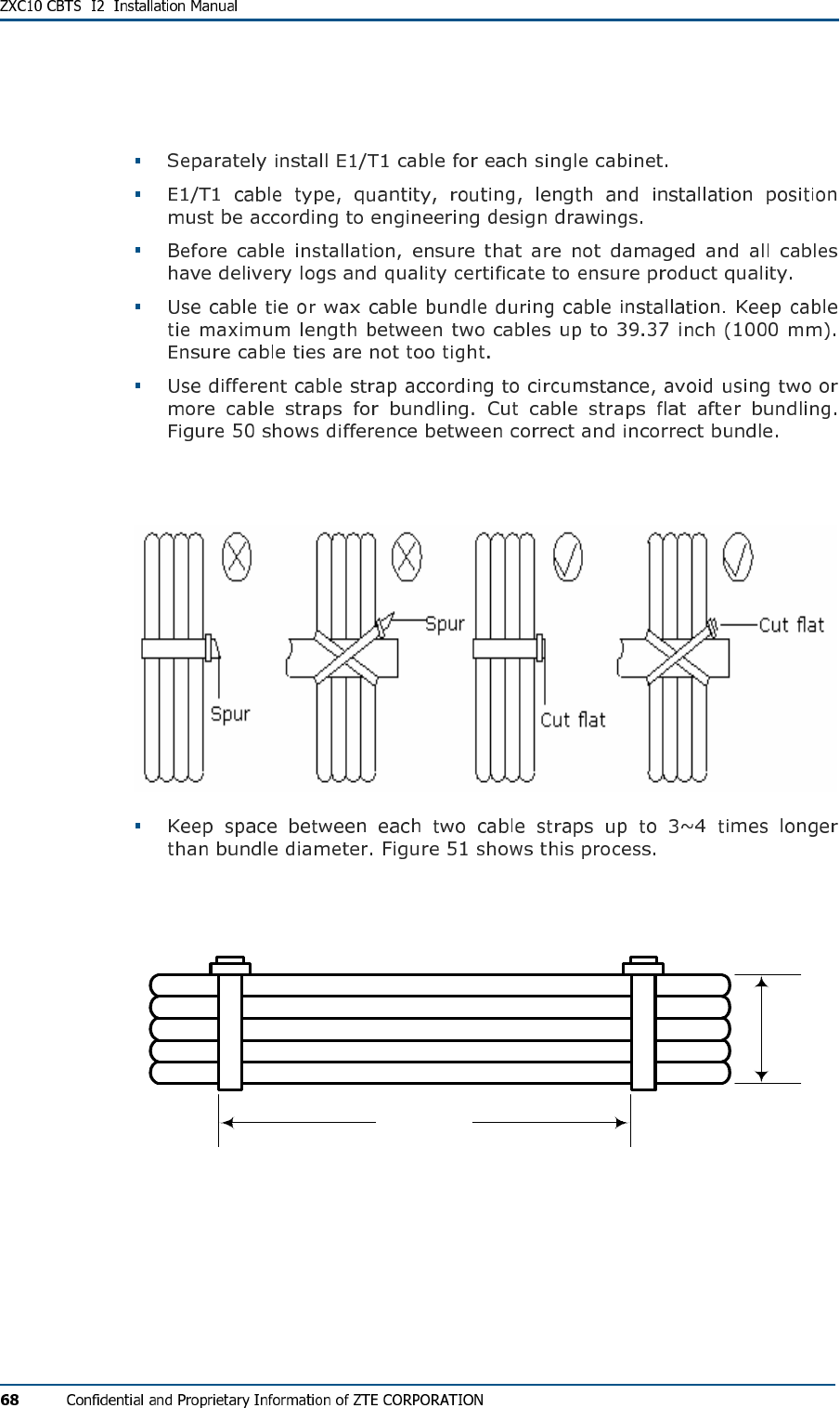
FIG U R E 50 - CAB LE STR AP S RE Q U I RE M E N TS
FIG U R E 51 - CAB LE ST R A P S
d
3d~4d
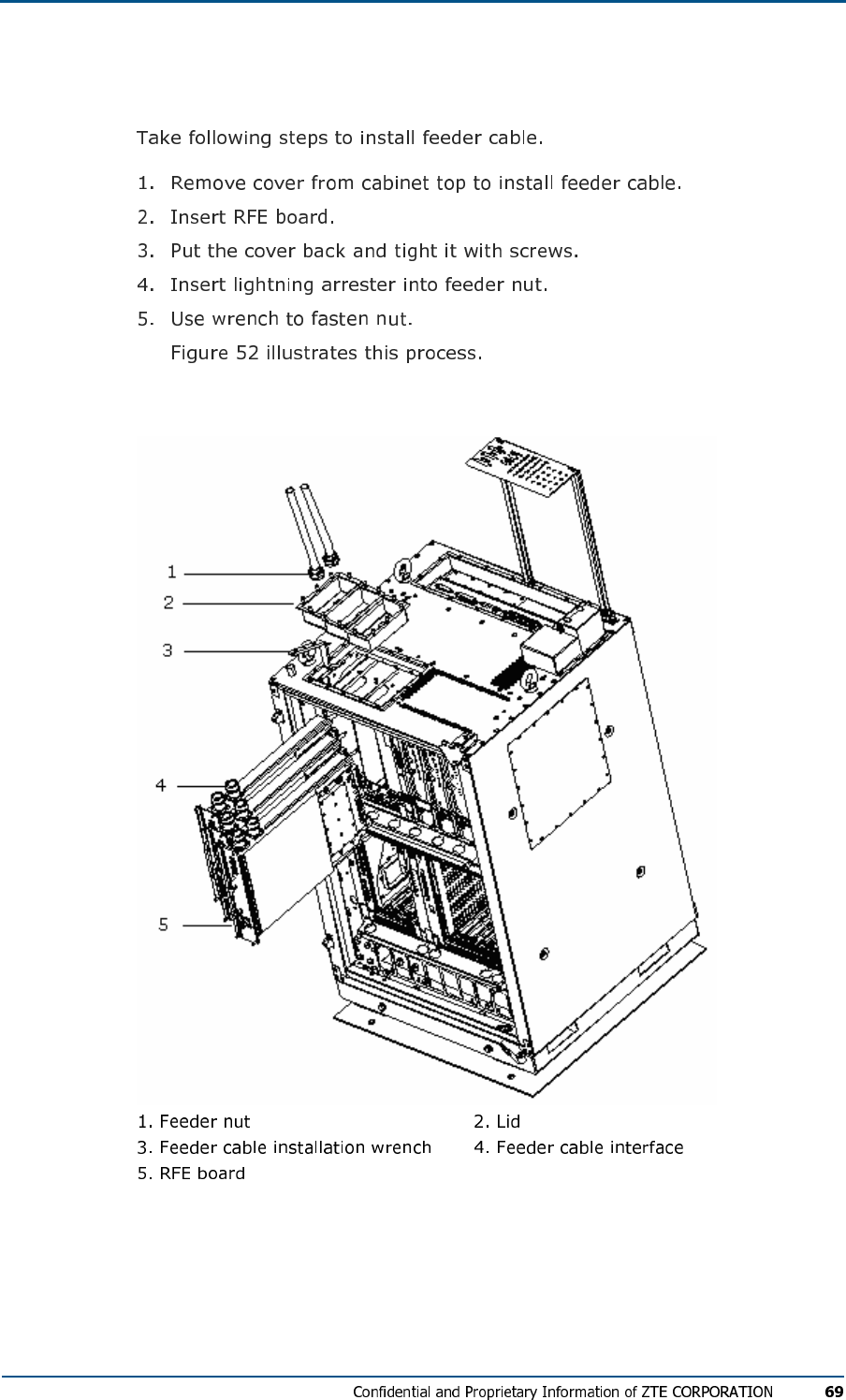
Feeder cable installation
FIG U R E 52 - FE ED ER CAB L E IN S T AL L ATI O N

C h a p t e r 5
Monitoring System Installation
This chapter describes monitoring system installation
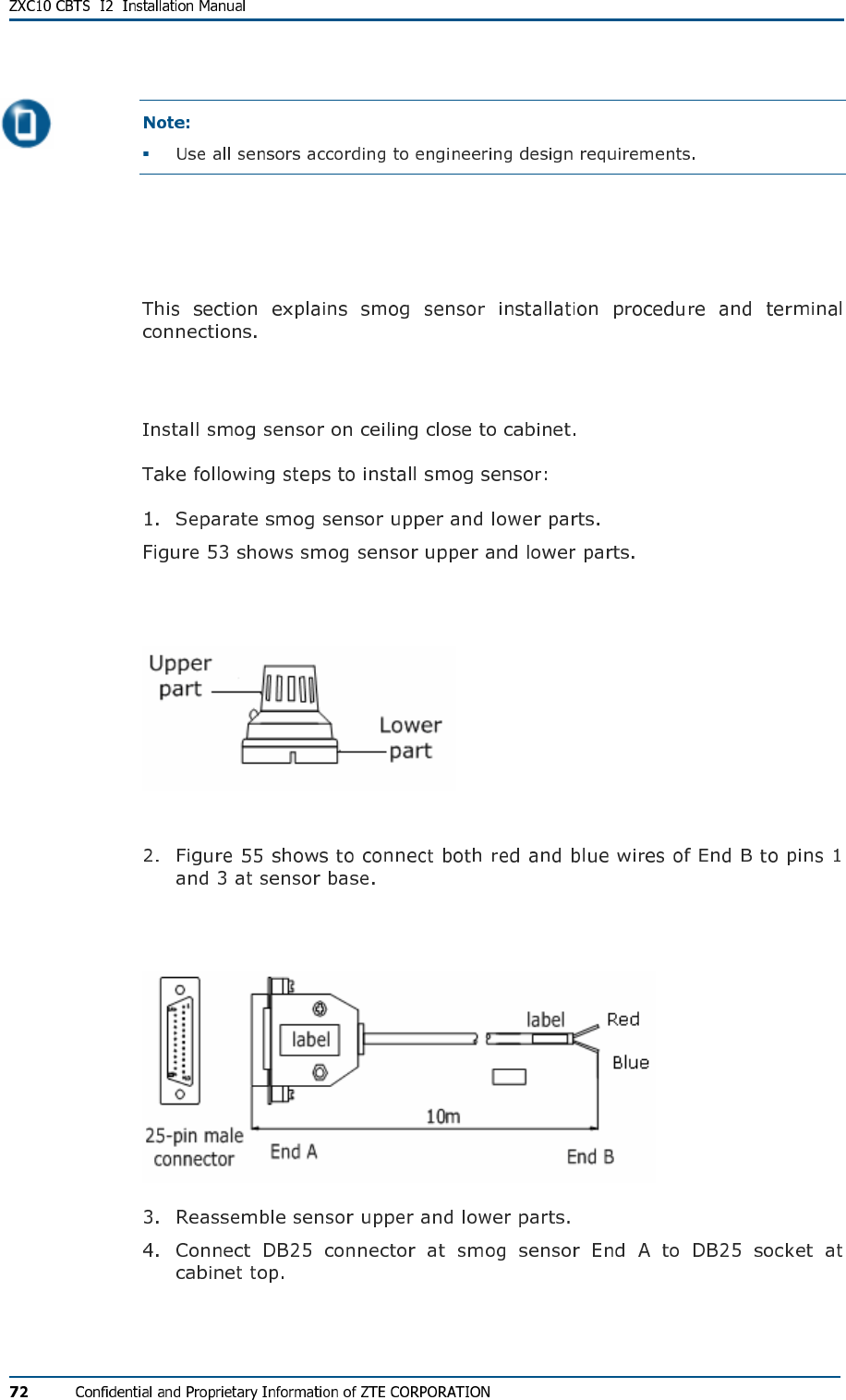
Smog Sensor Installation
Installation Procedure
FIG U R E 53 - SM OG SE N S O R
FIG U R E 54 - SM OG SEN SO R CA B LE
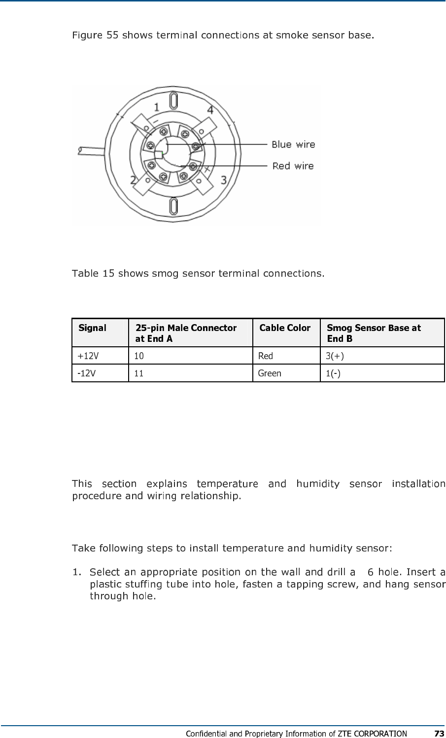
FIG U R E 55 - TE RM IN AL CO N NEC TI ON S AT SM OK E SE NS O R BA S E
Terminal Connections
TABL E 15 - TE RM IN AL CON N EC TIO NS
Temperature and Humidity
Sensor Installation
Installation Procedure
Φ
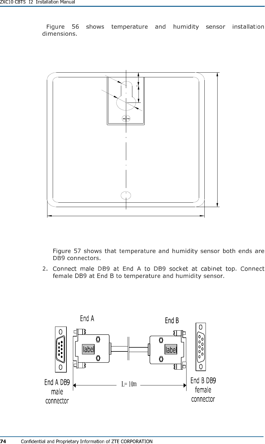
FIG U R E 56 - TE MP ER AT UR E AN D HUM IDI TY SEN SO R INS TAL L ATI ON (UN I T : MM )
R 2
610
F 2
8 4
90
FIG U R E 57 - TE MP ER AT UR E AN D HUM IDI TY SEN SO R CAB L E
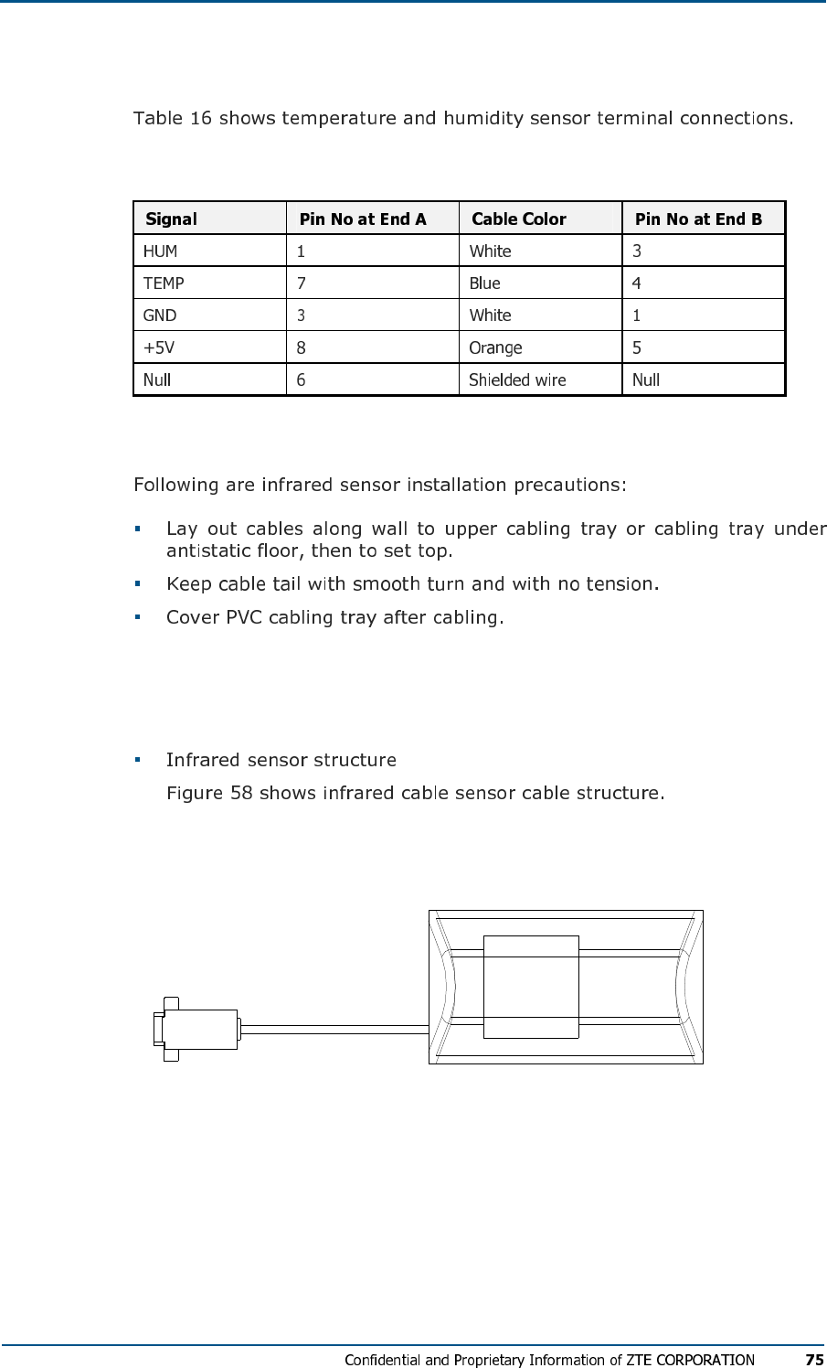
Terminal Connections
TABL E 16 - TE MP ER AT UR E AN D HUM ID IT Y SE NS OR WI RIN G R E L A T I O N S H I P
Installation Precautions
Infrared Sensor Installation
FIG U R E 58 - IN FR AR ED SE NS OR CAB LE ST R U C TU RE
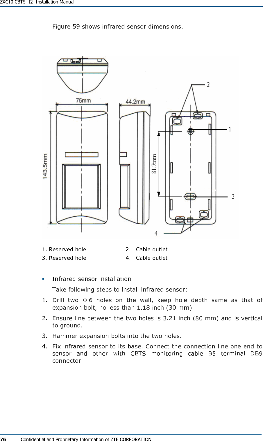
FIG U R E 59 - IN FR AR ED SE NS OR DI M E N SI O N S
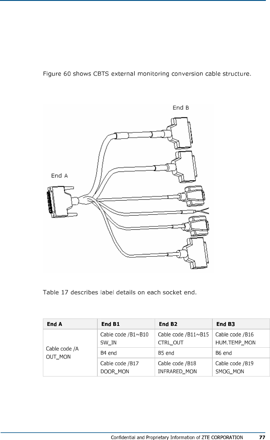
External Monitoring Cable
Installation
FIG U R E 60 - CBTS EX T E R N AL MON I T O R I N G CO N V E R S I ON CAB LE
TABL E 17 - EX TE RN AL MON IT OR IN G CON VE RS IO N CAB LE LAB EL S
C h a p t e r 6
Main Antenna Feeder System
Installation
This chapter describes main antenna feeder system installation:
Main Antenna System Installation
Antenna Installation Preparation
Antenna Installation Precautions
Main Antenna Feeder System Structure
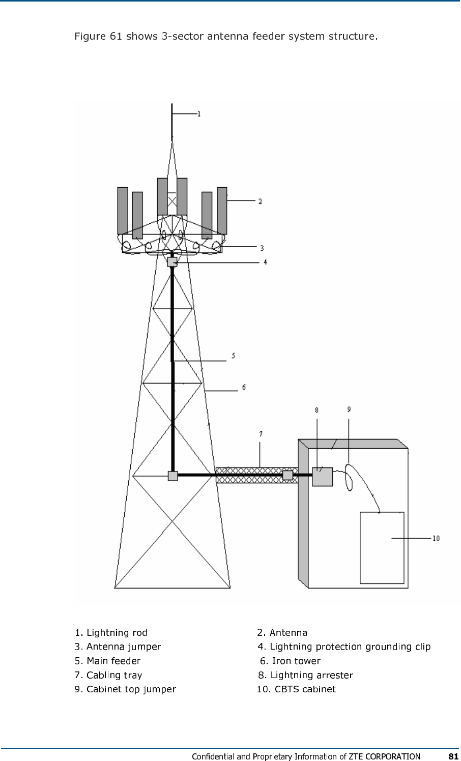
FIG U R E 61 - 3-SEC T O R AN T E NN A FE E D E R SY S T E M
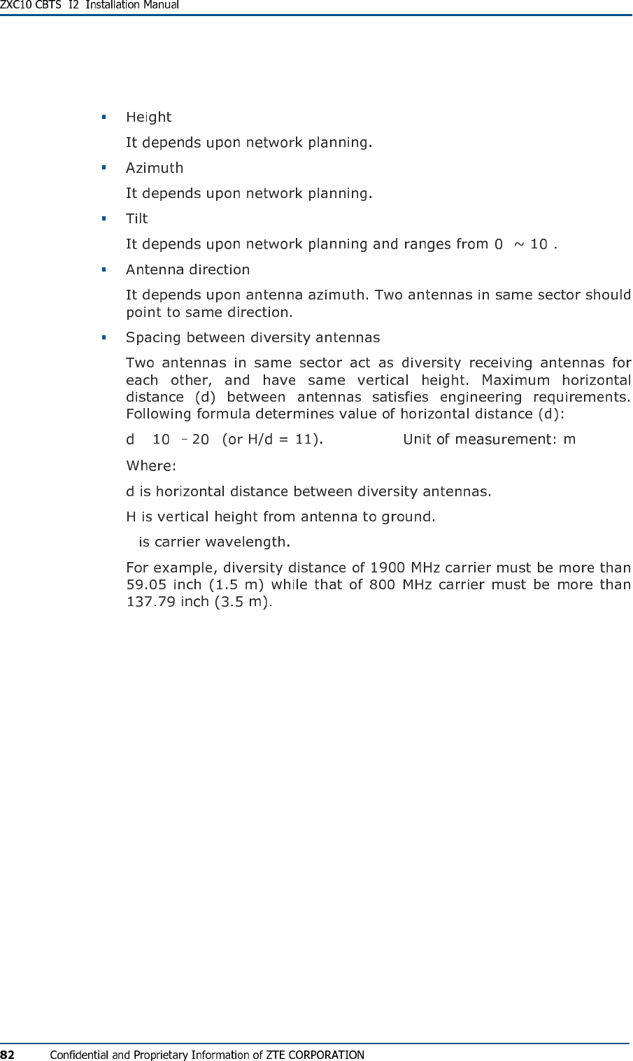
Antenna Installation Technical Parameters
° °
≥ λ λ
λ
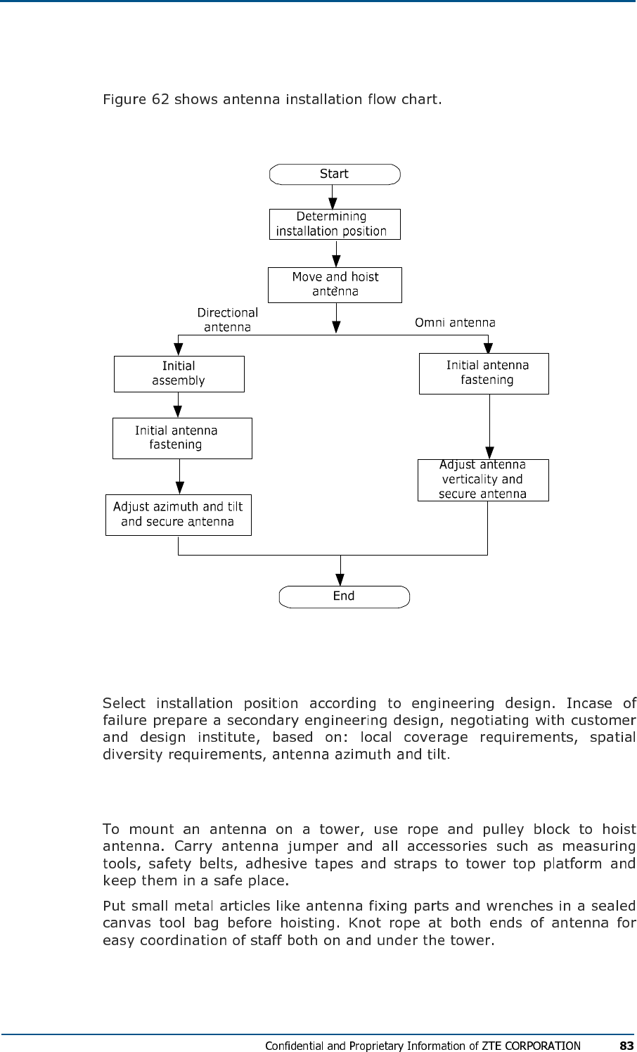
Antenna Installation Flow Chart
FIG U R E 62 - AN TE N NA INS TA LL ATI ON FLO W CH A R T
Selecting Installation Position
Moving and Hoisting Antenna
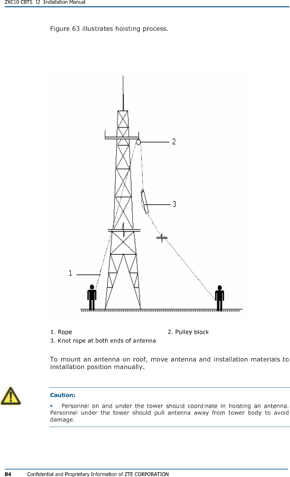
FIG U R E 63 - HO IS TI NG AN T E N N A
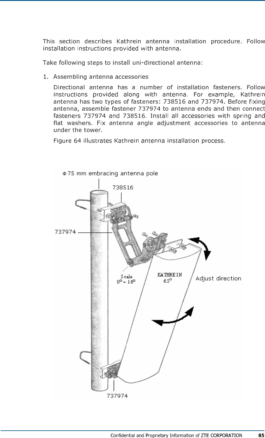
Uni-Directional Antenna Installation
FIG U R E 64 - KAT HR EI N AN TE N NA IN S T AL L A TI O N
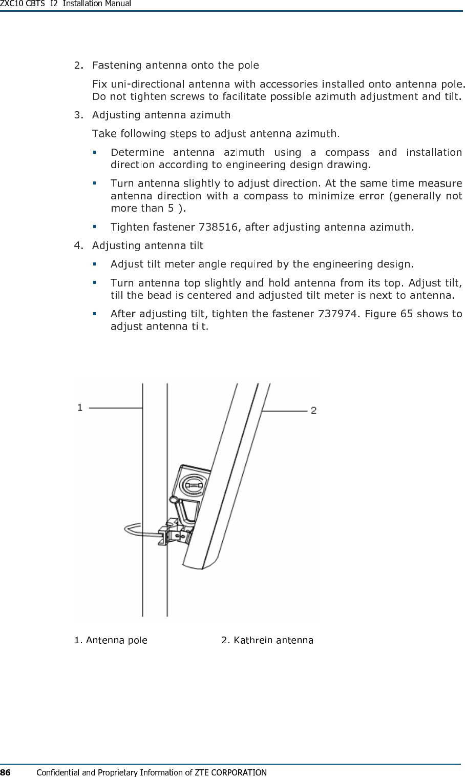
°
FIG U R E 65 - AD J US TIN G AN T EN N A TI L T
Omni-Directional Antenna Installation
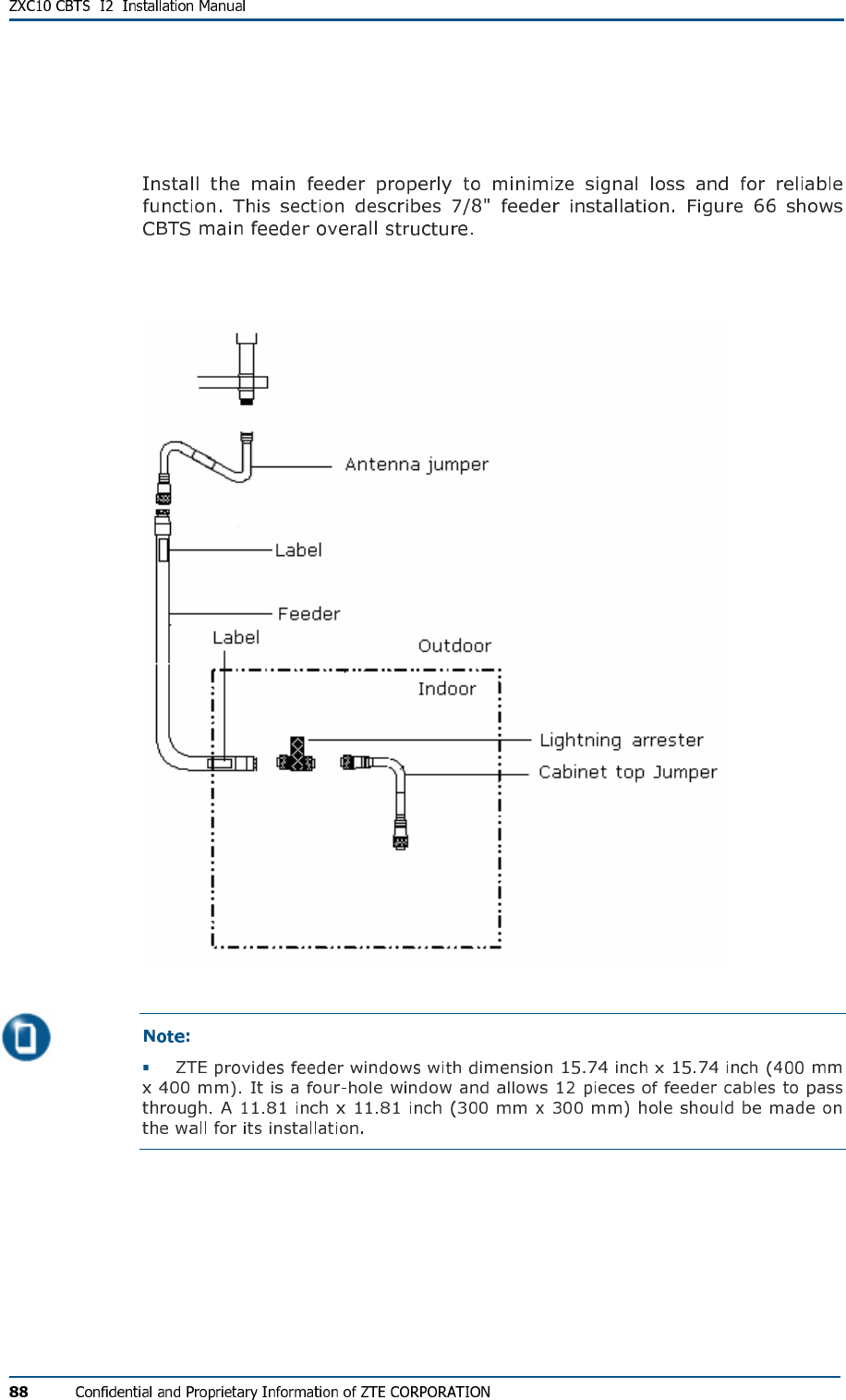
Main Feeder Installation
FIG U R E 66 - CBTS MAIN FE ED E R
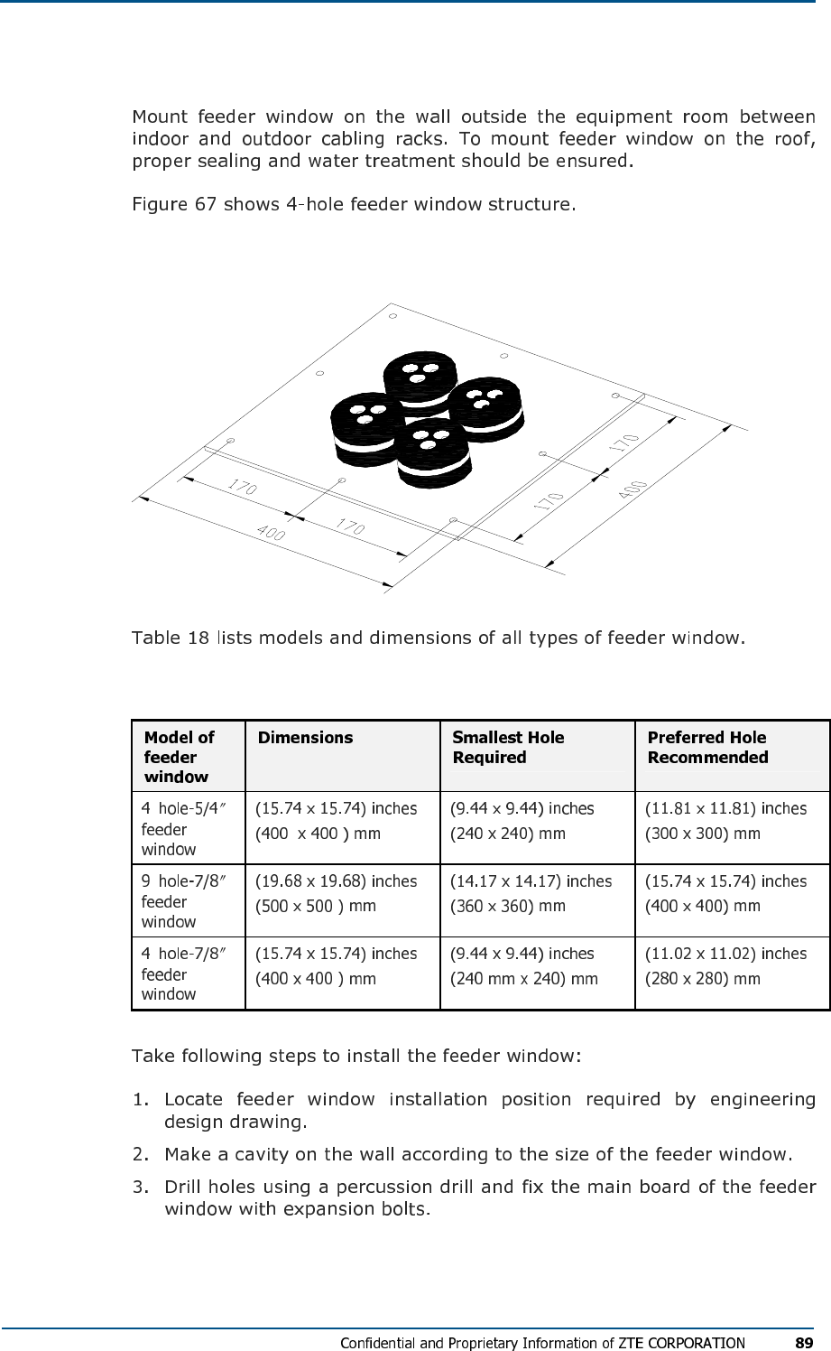
Feeder Window Installation
FIG U R E 67 - 4-HOL E FE ED ER WIN DOW (UN I T: M M)
TABL E 18 - FE ED ER MOD EL S AN D DIM EN SI ON S
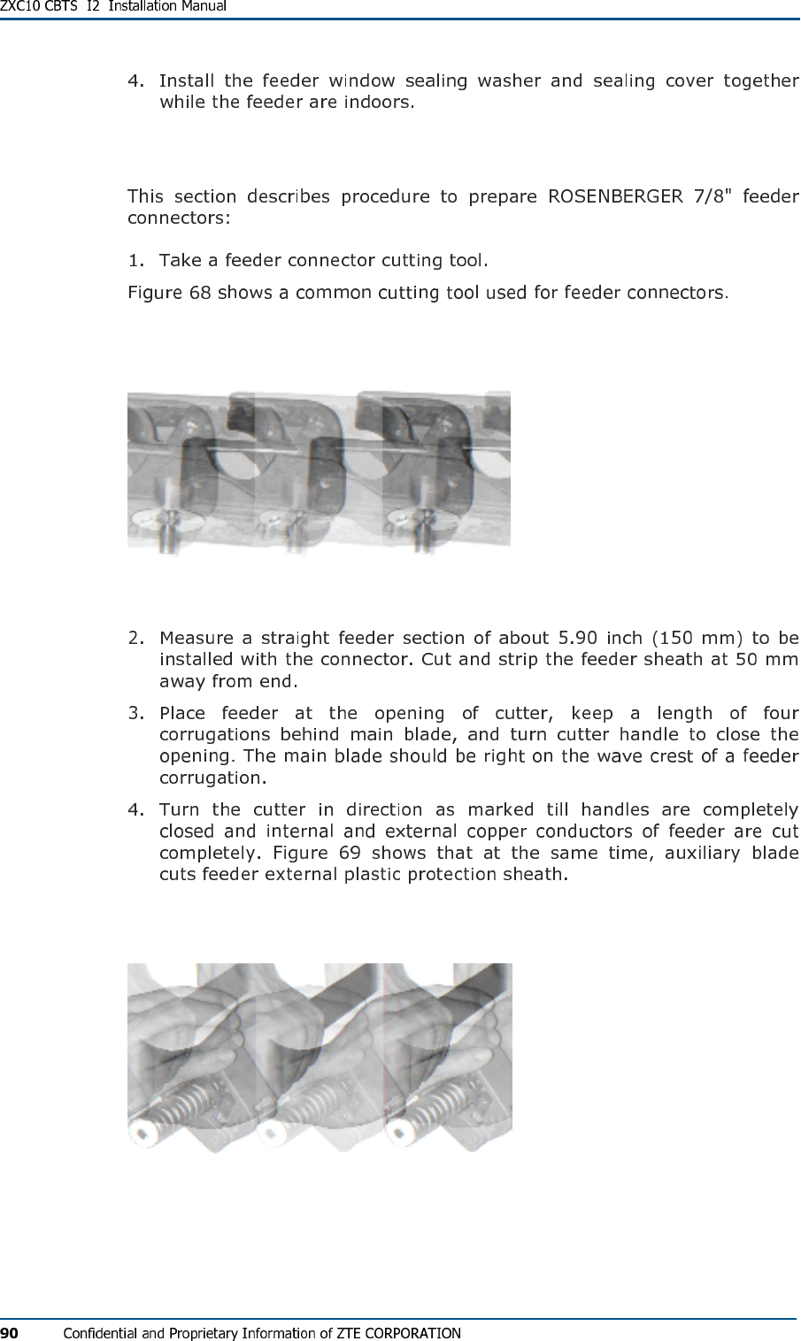
Feeder Connector Preparation
FIG U R E 68 - CU TT IN G TOO L FOR MAK IN G 7/8" FEE DE R CO NN E C TO R
FIG U R E 69 - CU TT IN G FE ED ER W IT H A CU T T E R
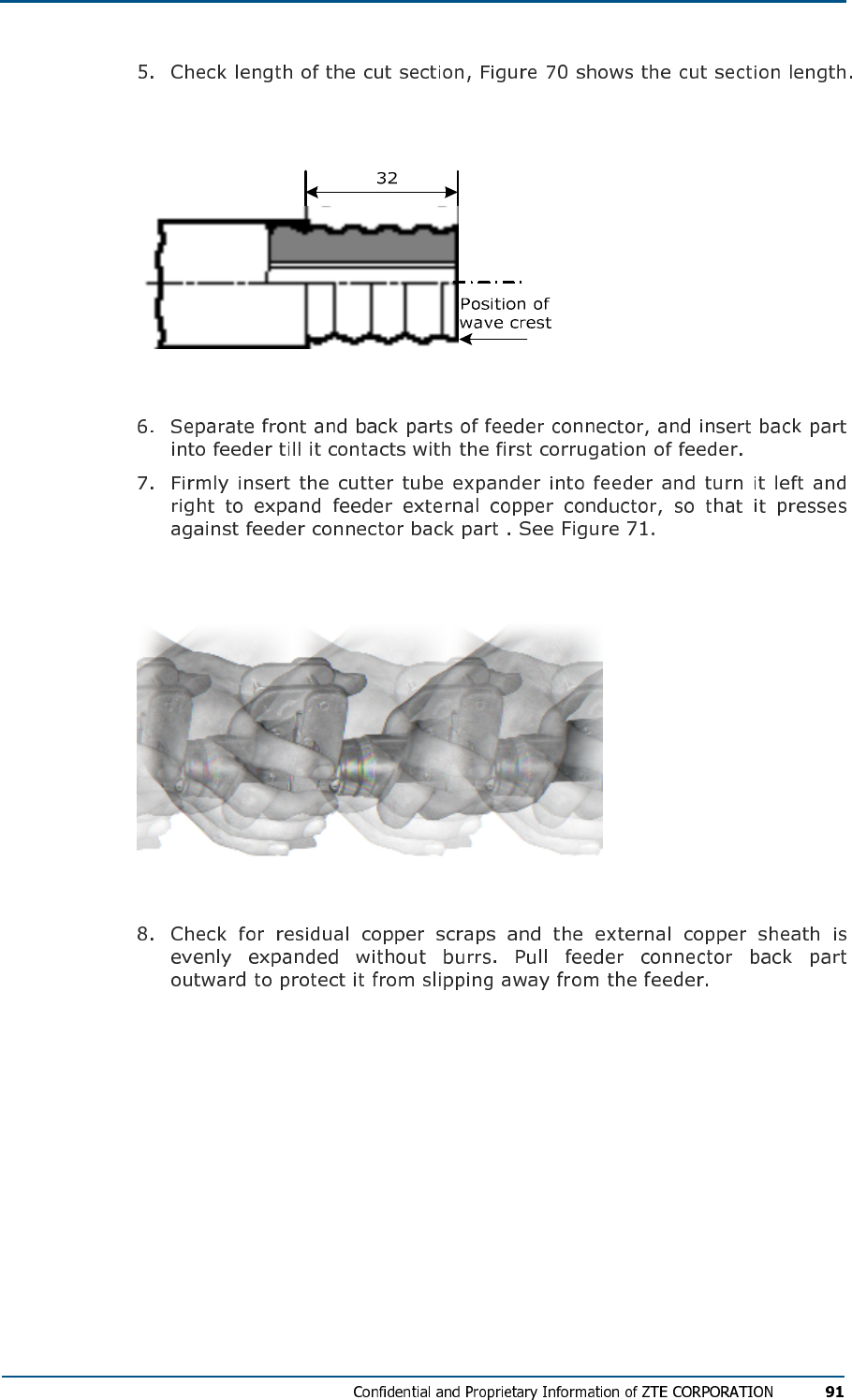
FIG U R E 70 - CH EC KI NG CU T SEC TIO N LEN GT H
FIG U R E 71 - FE ED ER EX P AND IN G EX TE RN AL CO ND UC TO R
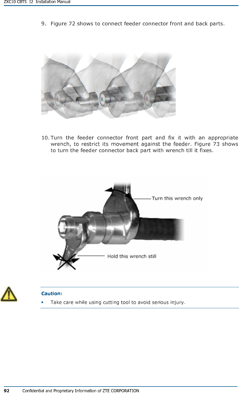
FIG U R E 72 - CO NN EC TI NG FRO NT AND BAC K PAR TS
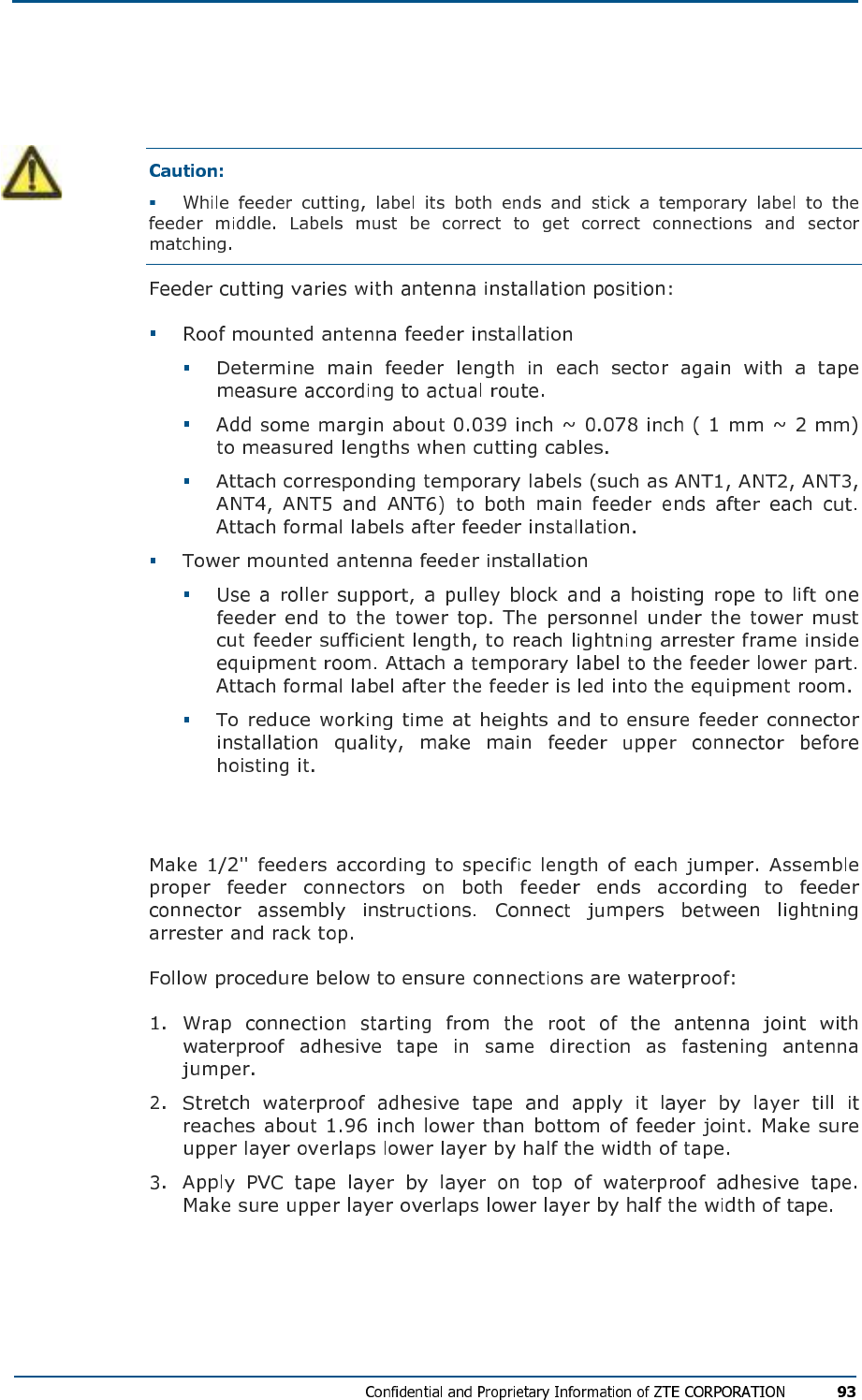
FIG U R E 73 - FI XI NG FEE DE R CON NE C TOR FR ON T AN D BACK PA R T S
Feeder Cutting
Jumper Installation
Waterproofing Joints
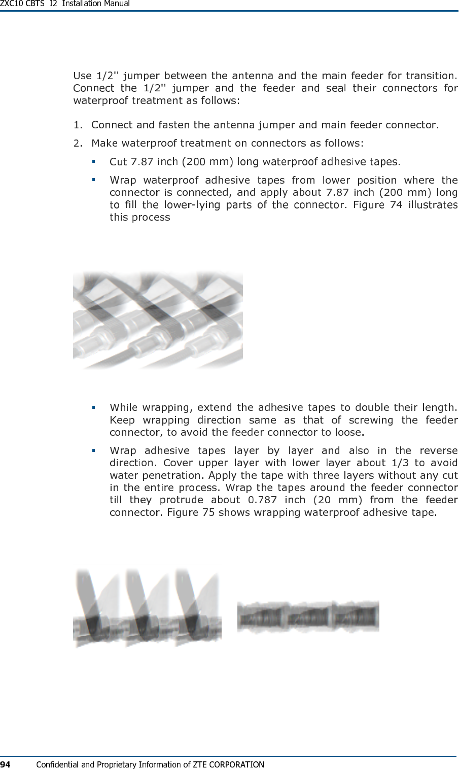
FIG U R E 74 - WR APP IN G WATE RP RO OF ADH ES IV E TAP E S (1)
FIG U R E 75 - WR APP IN G WATE RP RO OF ADH ES IV E TAP E S (2)
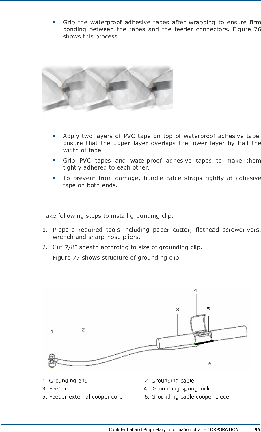
FIG U R E 76 - WR APP IN G 9 WATE RP RO OF ADH E SI VE TAP E S (3)
Feeder Grounding Clip Installation
FIG U R E 77 - GR OU ND IN G CL I P
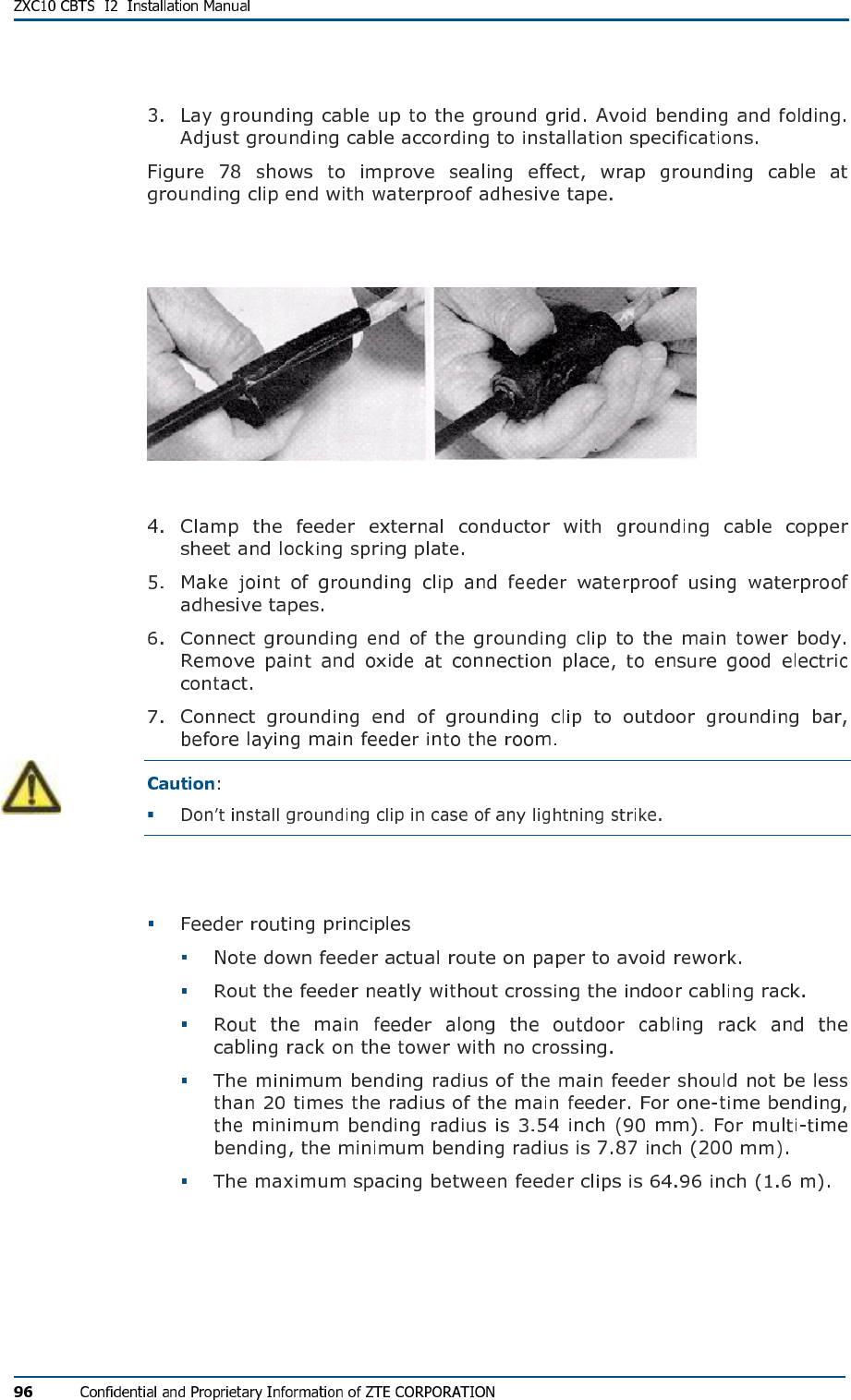
FIG U R E 78 - WR APP IN G GRO UN DI NG CAB LE
Routing Feeders
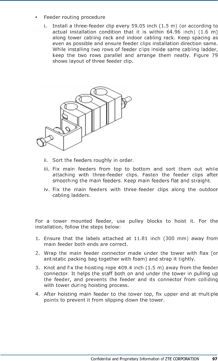
FIG U R E 79 - TH R E E -FEE DE R CL I P
Hoisting Feeders to Tower
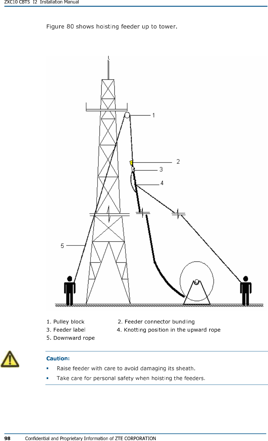
FIG U R E 80 - HO IS TI NG FE ED ER UP T O TO W E R
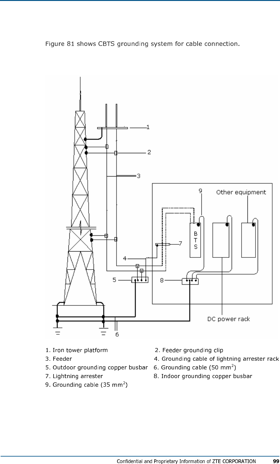
CBTS Grounding System
FIG U R E 81 - BTS GRO UN DI NG SYS TE M CABL E CON NE CT IO N
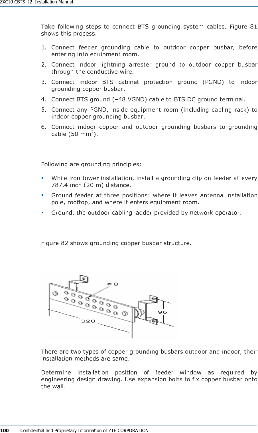
Grounding Principles
Grounding Copper Busbar Installation
FIG U R E 82 - OU TE R VIE W OF GR OU ND IN G COPP ER B US B A R (UN I TS MM )
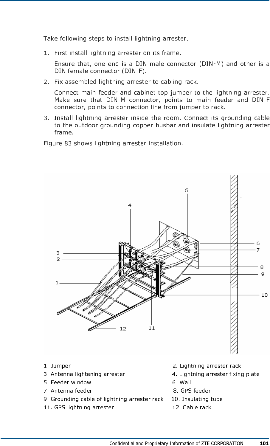
Lightning Arrester Installation
FIG U R E 83 - LI GH TN IN G AR R ES TER FR AM E IN S T AL L AT I O N
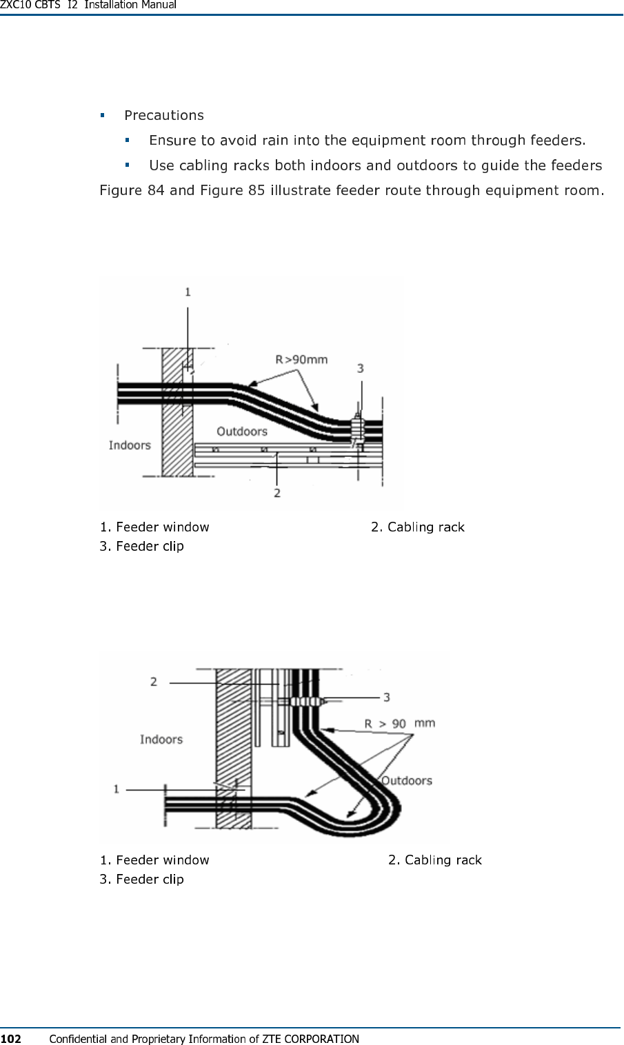
Routing Feeders into Equipment Room
FIG U R E 84 - RU NN IN G FE ED ER S IN TO EQ UIP ME N T RO O M (M E T HO D 1)
FIG U R E 85 - RU NN IN G FE ED ER S IN TO EQ UIP ME N T RO O M (M E T HO D 2)

C h a p t e r 7
GPS Antenna Feeder System
Installation
This chapter describes GPS antenna feeder system installation:
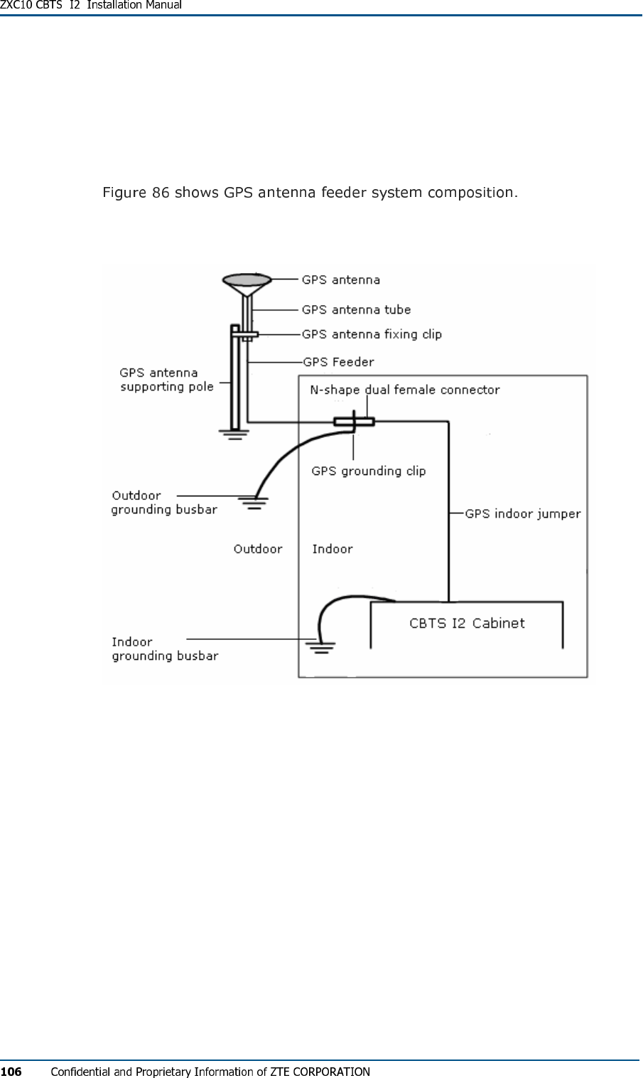
GPS Antenna Feeder System
Structure
FIG U R E 86 - GPS AN T E N N A FE ED ER SY S TE M
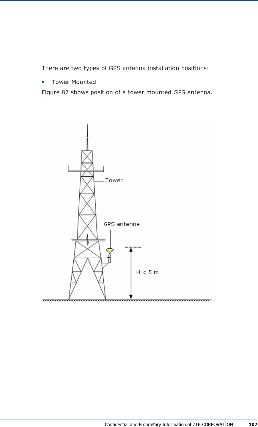
Installation Position and
Requirements
FIG U R E 87 - TO WE R MOUN TE D GPS AN T E N N A
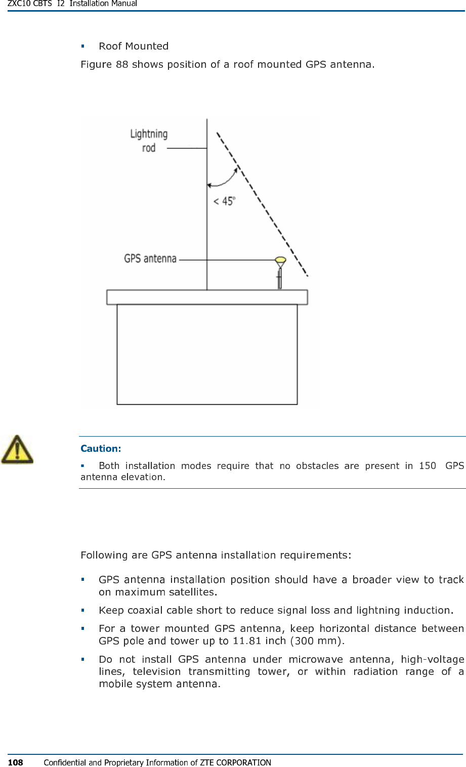
FIG U R E 88 - RO OF MOU NT ED GPS AN T E N N A
°
Installation Requirements
Lightning Protection Requirements
°
NJ-9 Connector Preparation
NJ-9 Connector
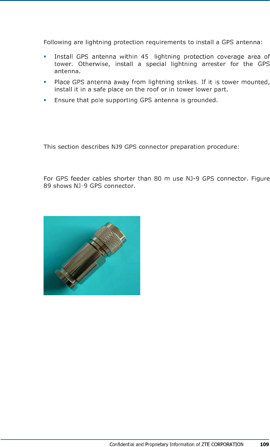
FIG U R E 89 - NJ-9 GPS CO N N E C TO R
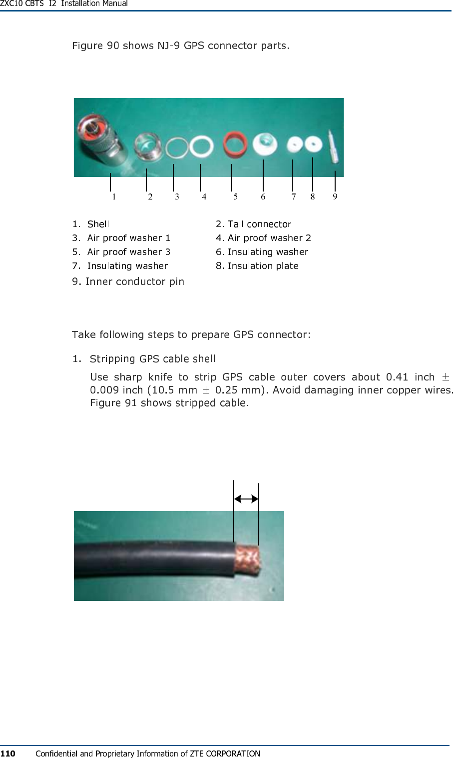
FIG U R E 90 - NJ-9 GPS CO NN EC TO R PA R T S
Connector Preparation Procedure
FIG U R E 91 - STR IP PI NG GPS CA B L E
±
10.5 mm 0.25 mm
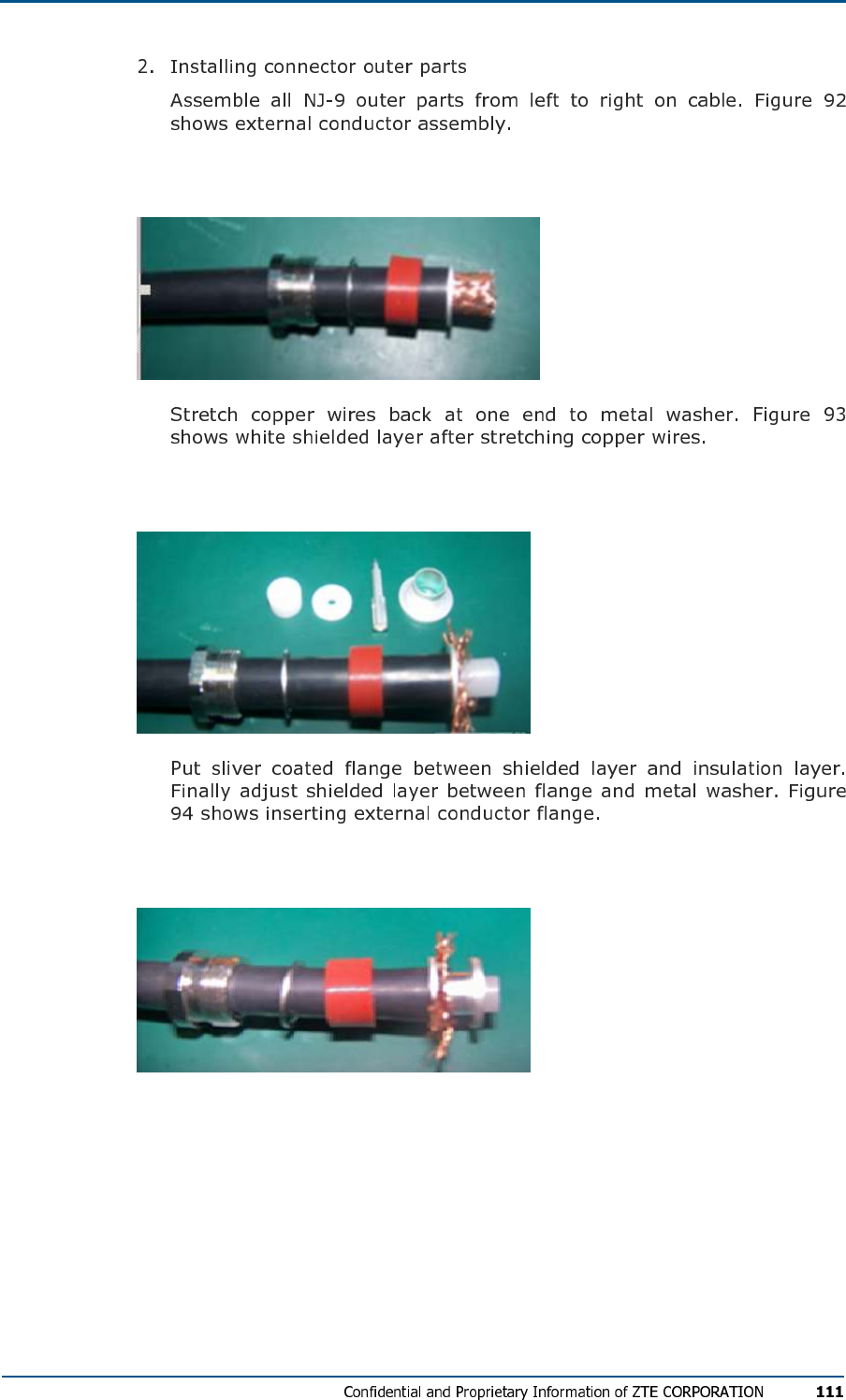
FIG U R E 92 - EX TE RN AL CO N DUC TO R AS S E M B L Y
FIG U R E 93 - SH IE LD ED LAY E R
FIG U R E 94 - IN SE R TIN G EXT ERN AL CO ND UC TO R FL A N G E
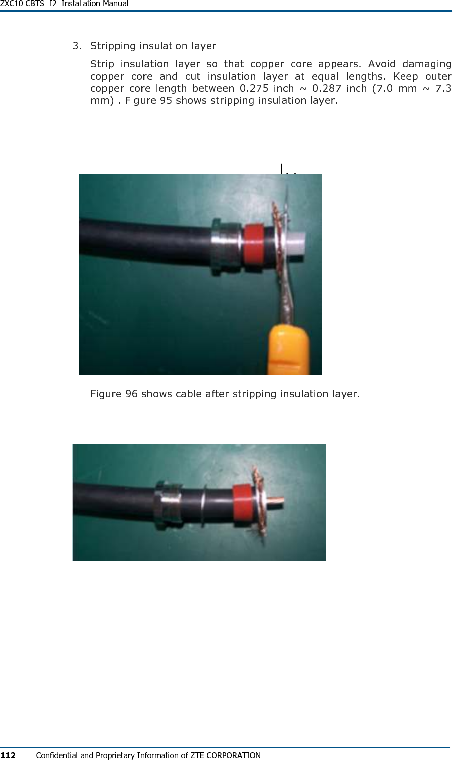
FIG U R E 95 - STR IP PI NG INS U LAT IO N LAY E R
7.0 mm ~ 7.3 mm
FIG U R E 96 - AF TE R STR IPP I NG INS UL ATI ON LA YER
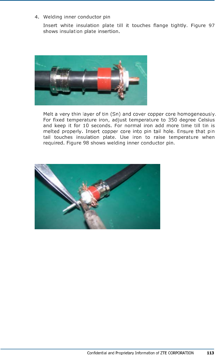
FIG U R E 97 - IN SE R TIN G INS UL ATI N G PL A T E
FIG U R E 98 - WE LDI NG IN NE R CON DU CT OR PI N
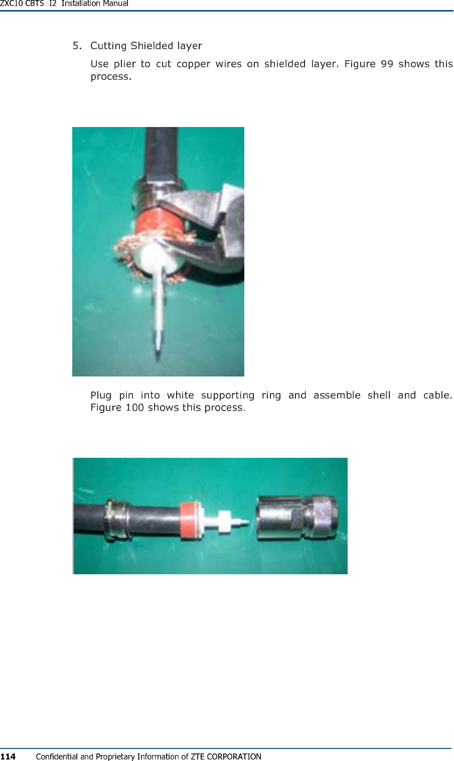
FIG U R E 99 - CU TT IN G SH IE LD ED LA Y E R
FIG U R E 100 - ASS E M BL IN G SHE L L AN D CA B LE
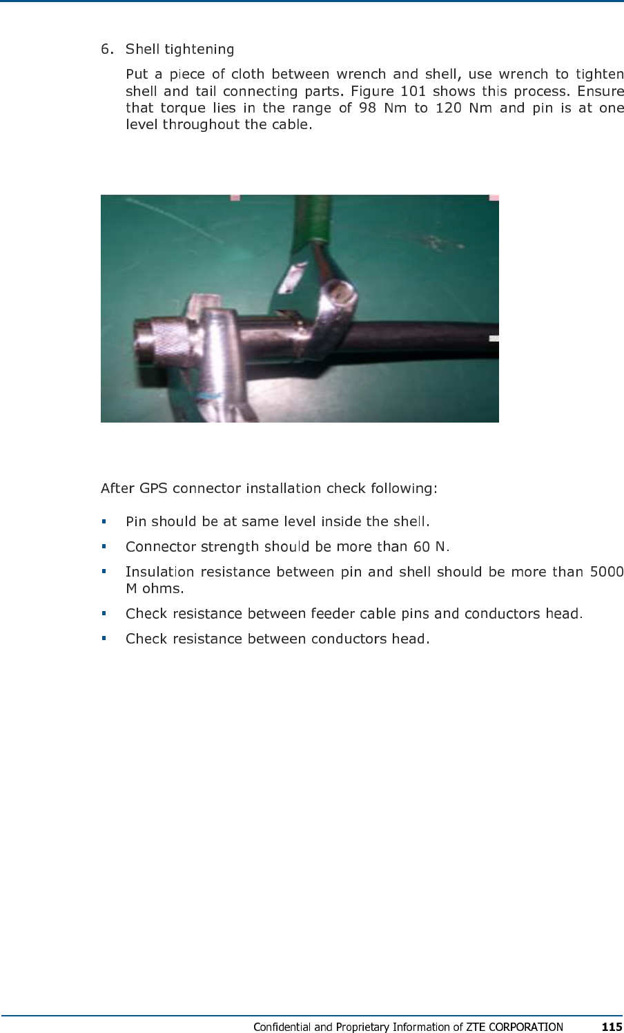
FIG U R E 101 - SHE LL TI G H TE N IN G
GPS Connector Installation check

C h a p t e r 8
Board Installation
This chapter describes CBTS board installation:
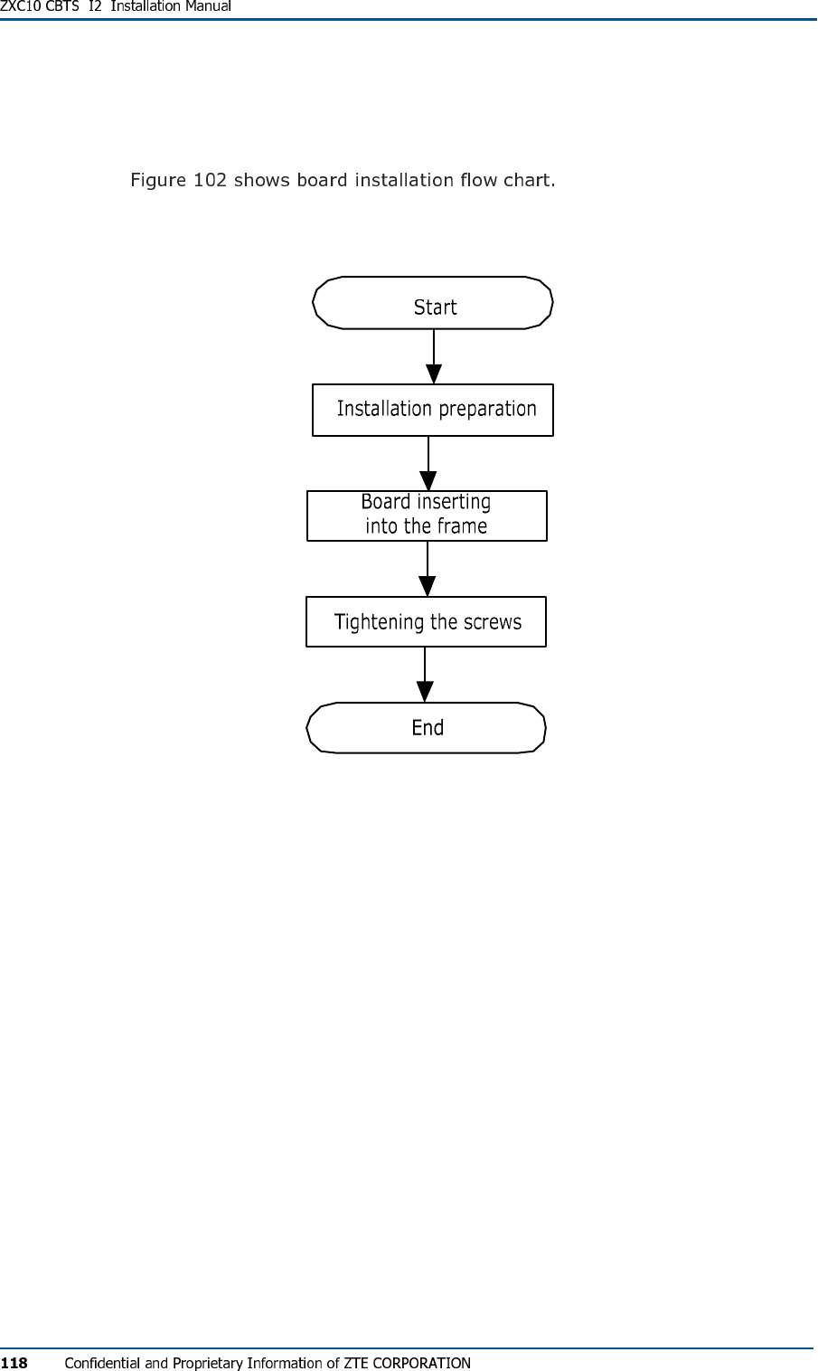
Installation Flow Chart
FIG U R E 102 - BO ARD IN ST AL L AT I O N FL O W CH A R T
Installation Procedure and
Precautions
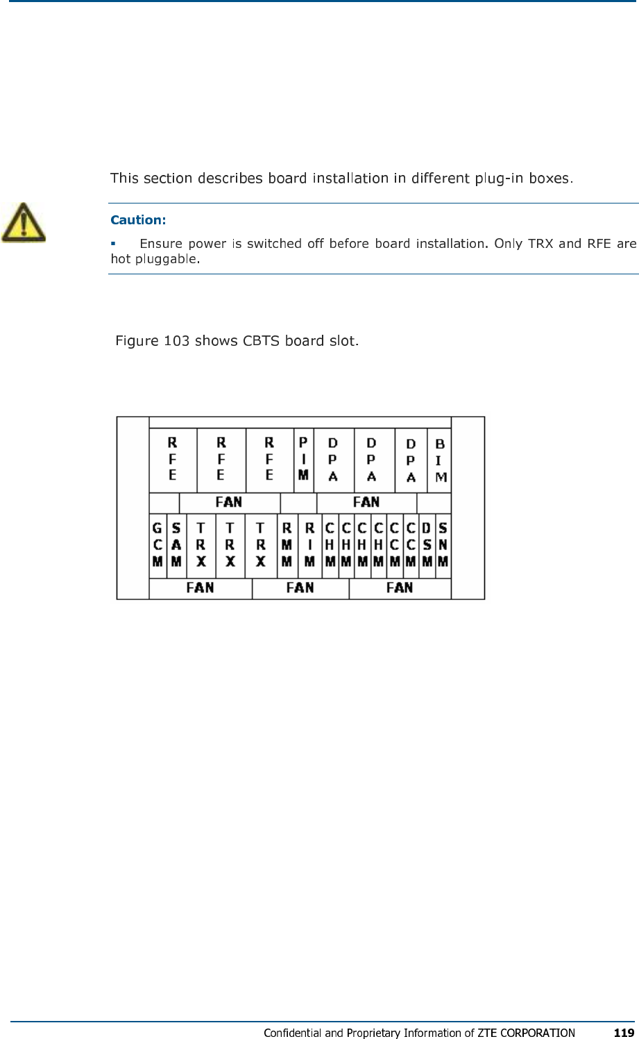
CTSB Board Slot
FIG U R E 103 - CBTS BO AR D SL O T
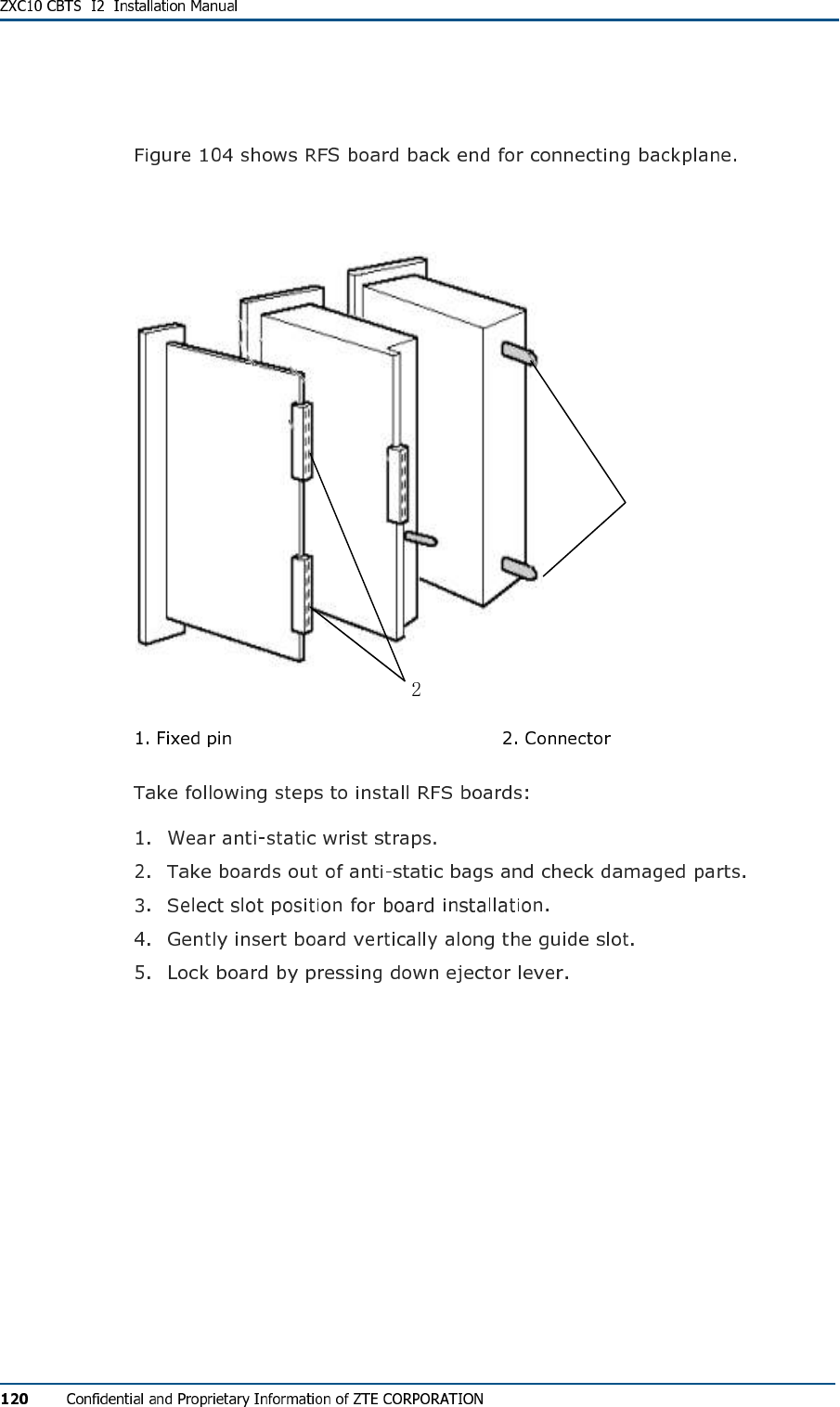
RFS Board Installation
FIG U R E 104 - RFS BOAR D BA C K -EN D
1
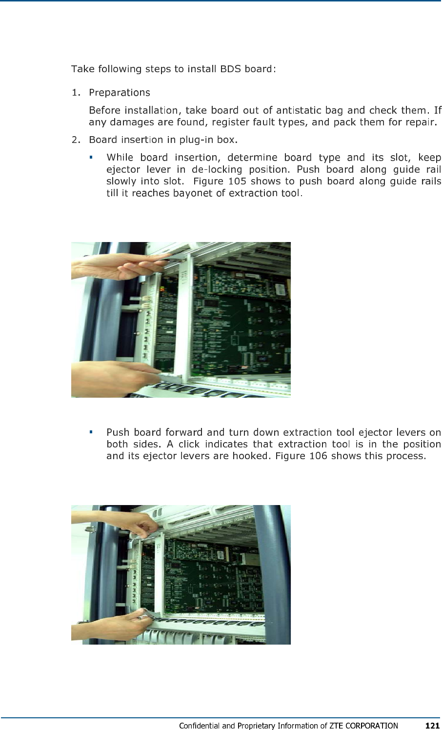
BDS Board Installation
FIG U R E 105 - BO ARD PL UG G I N G (STE P 1)
FIG U R E 106 - BO ARD PL UG G I N G (STE P 1)
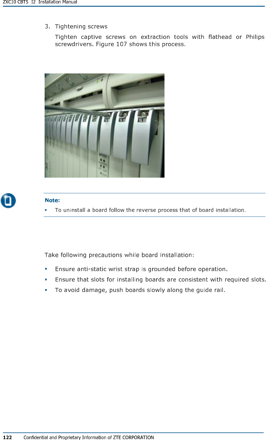
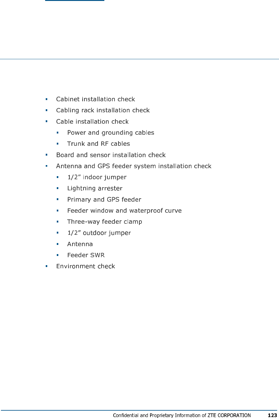
FIG U R E 107 - BO ARD PL UG G I N G (STE P 3)
Installation Precautions
C h a p t e r 9
Hardware Installation Check
This chapter describes CBTS hardware installation check:
Cabinet Installation Check
Cabling Rack Installation Check
Cable Installation Check
Power and Grounding Cables
Trunk and RF Cables
Board and Sensor Installation
Check
Antenna and GPS Feeder
System Installation Check
1/2” Indoor Jumper
Lightning arrester
Main GPS Feeder
Feeder Window and Waterproof Curve
Three – Way Feeder Clamp
1/2” Outdoor Jumper
Antenna
Feeder SWR
Environment Check
C h a p t e r 10
Power On and Off Mechanism
This chapter describes:
Power Supply Inspection
Power-on Procedure
First Time Power-on
Normal Power-on
Power-off Procedure

A p p e n d i x A
Packing, Storage and
Transportation
This appendix describes:
Packaging
Cabinet packing
FIG U R E 108 - WOOD E N PAC KI N G BO X F O R CA B I N E T
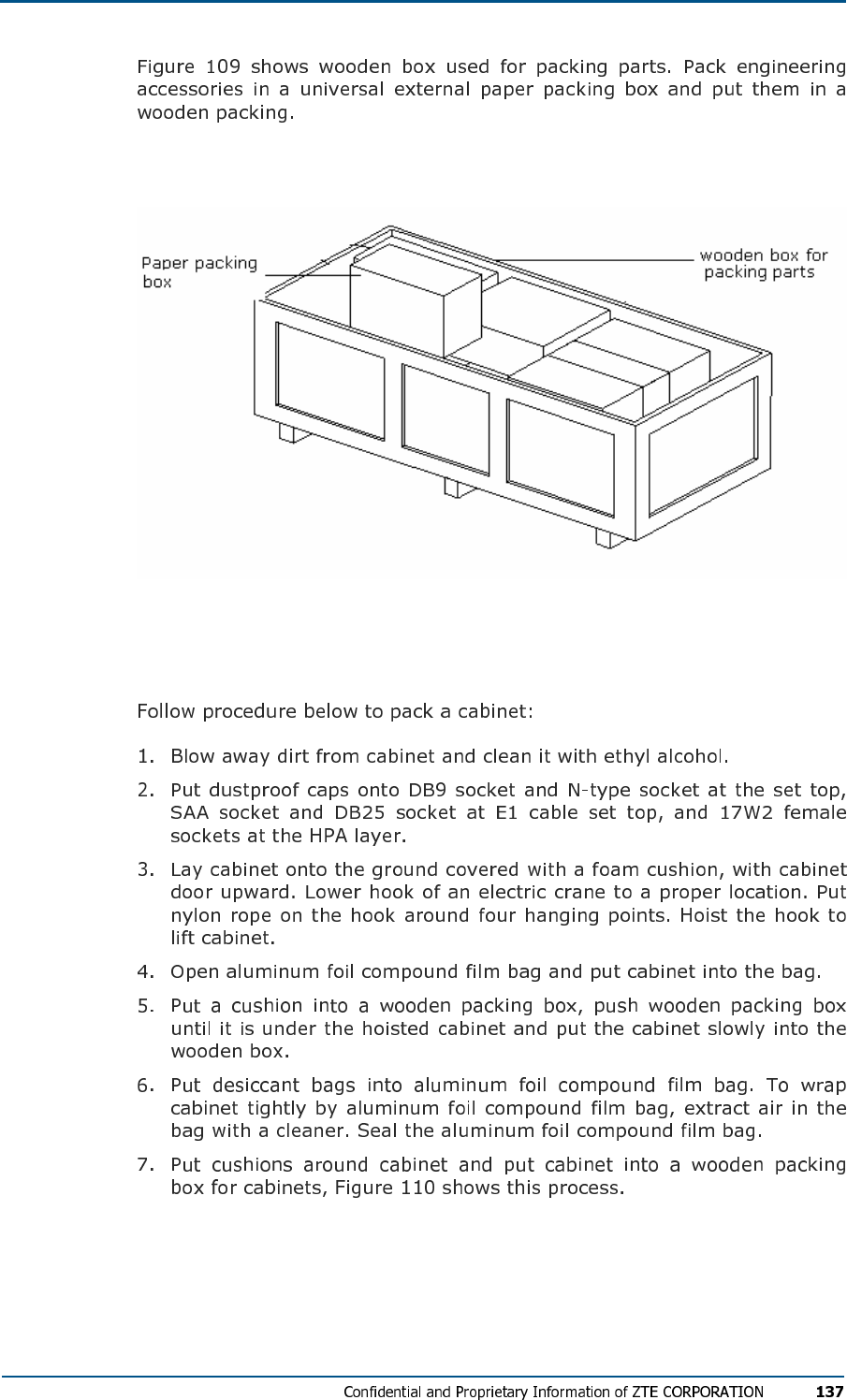
FIG U R E 109 - WOOD E N PAC KI N G BO X F O R PA R T S
Cabinet Packing Procedure
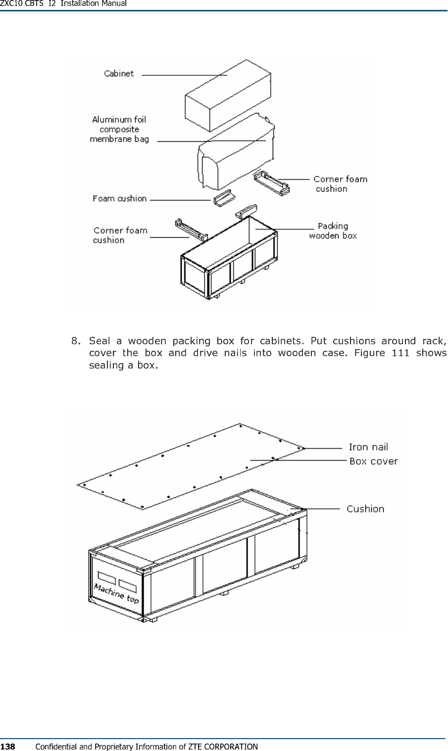
FIG U R E 110 - CABI NE T PA C K I N G
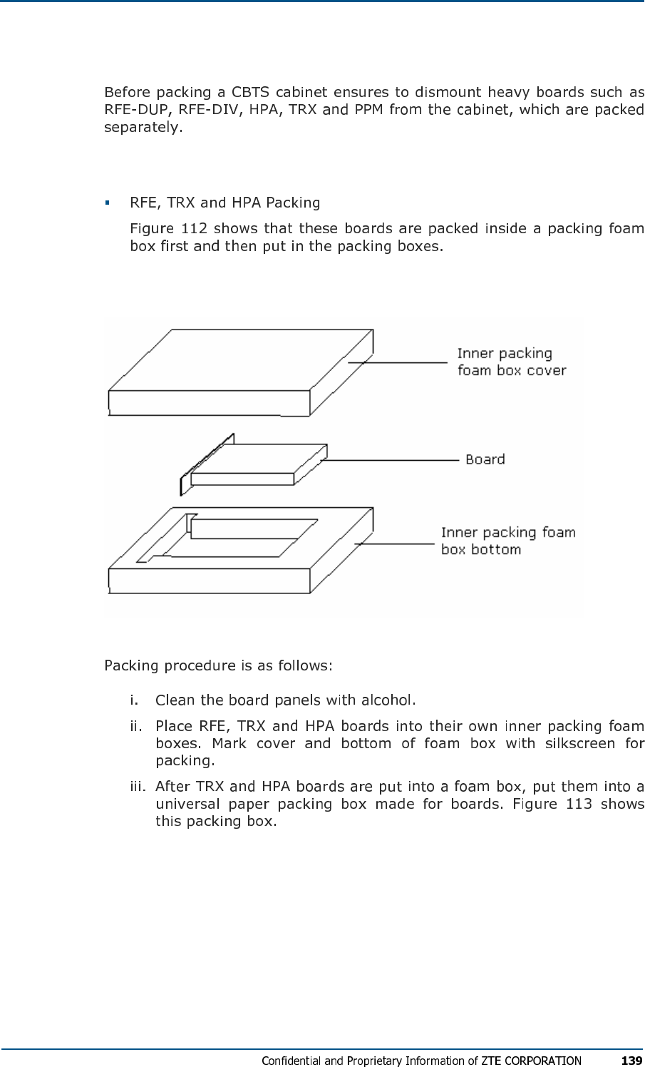
FIG U R E 111 - SE ALI N G A BO X
Board Packing
Board packing procedure
FIG U R E 112 - INNER PACK IN G FO A M BO X
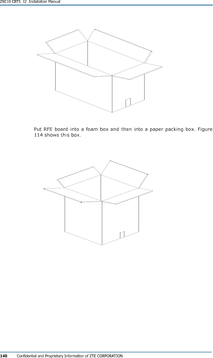
FIG U R E 113 - GEN ER AL PAP E R PA C K I N G BO X F O R BO AR D S
FIG U R E 114 - PAPE R PA C K I N G BO X F O R RFE BO A R D S
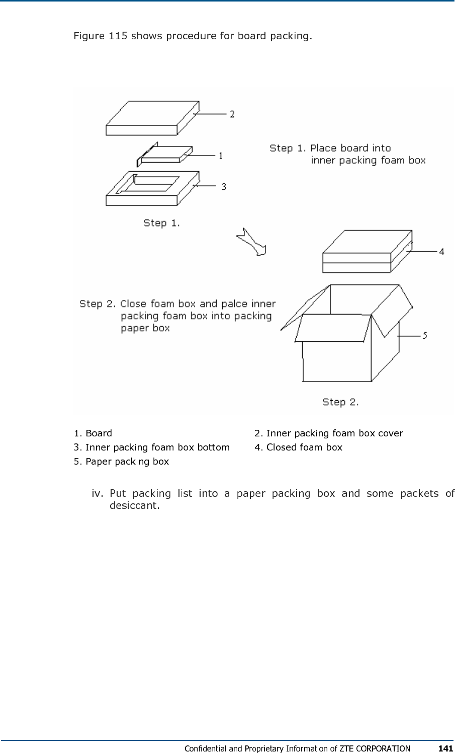
FIG U R E 115 - PACK IN G RFE, HP A AN D TRX BO A R D
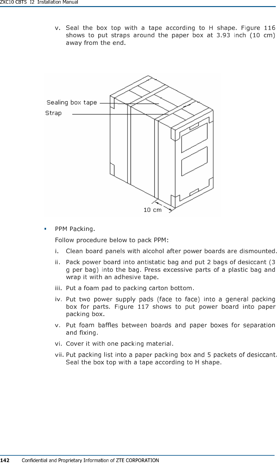
FIG U R E 116 - SE ALI N G A N D PA C K IN G
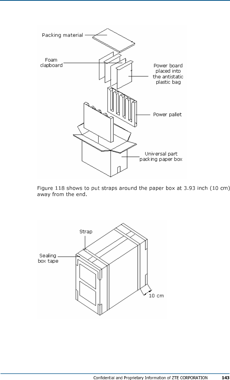
FIG U R E 117 - PACK IN G PO W ER BO AR D
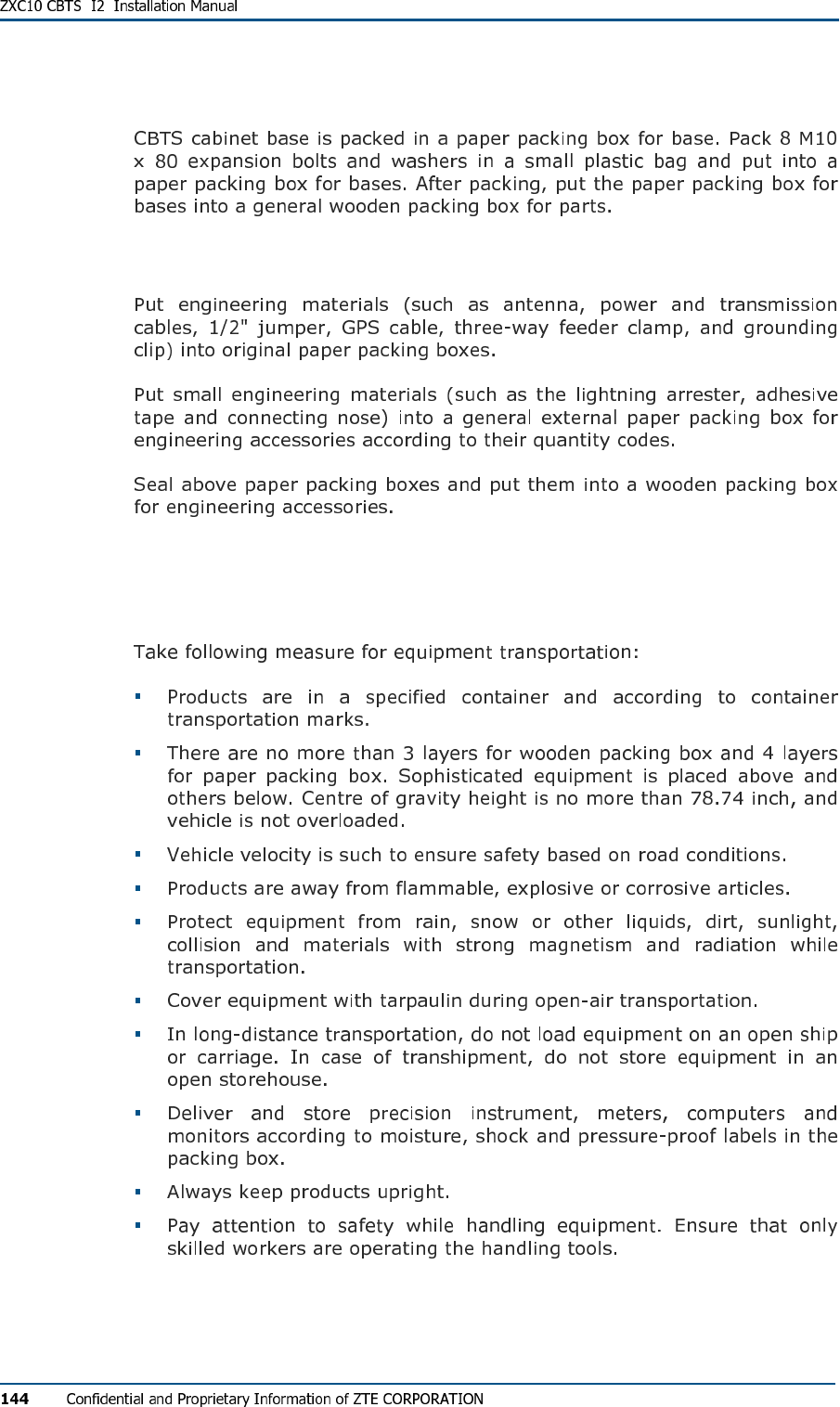
FIG U R E 118 - SE ALI N G PO W E R BO A R D PAC K I N G BOX
Base Packing
Engineering Materials Packing
Transportation
Storage

A p p e n d i x B
SiteMaster Usage
This appendix describes SiteMaster usage:
Frequency Range Selection
SiteMaster Check
Feeder Input Parameters
Tester Installation
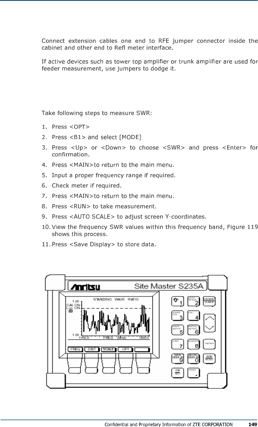
Measuring SWR
FIG U R E 119 - AN TEN N A FE E D ER SWR TEST
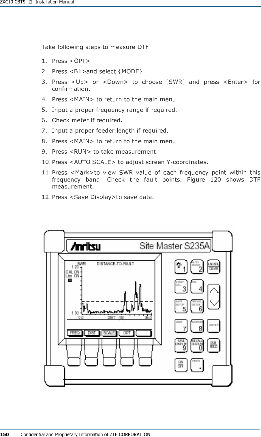
Measuring DTF
FIG U R E 120 - MEAS UR EM EN T O F AN T E N N A FE ED ER DTF
A p p e n d i x C
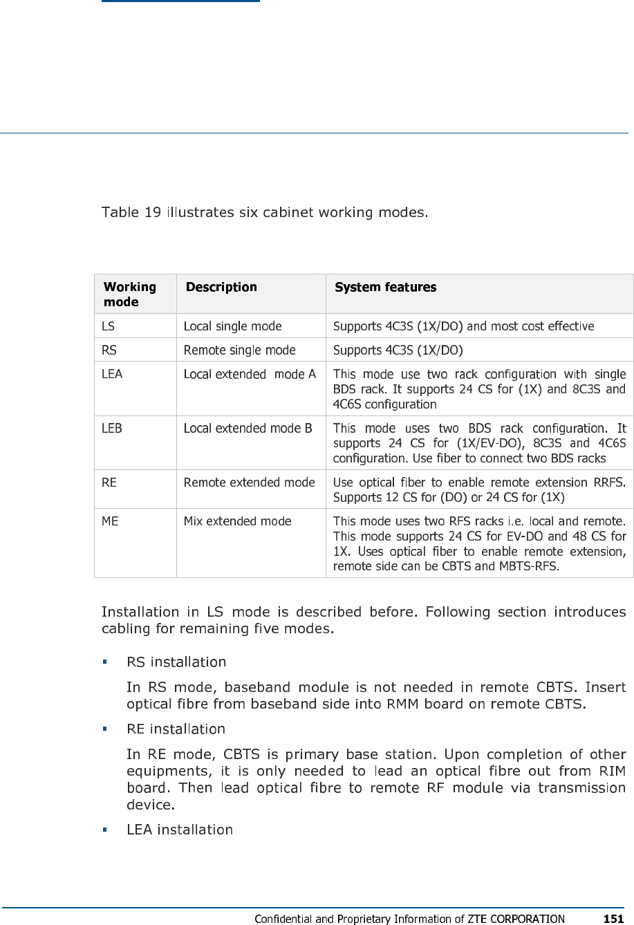
Cabinet Working Modes
This appendix describes cabinet working modes.
TABL E 19 - CBTS WOR K IN G MOD E S
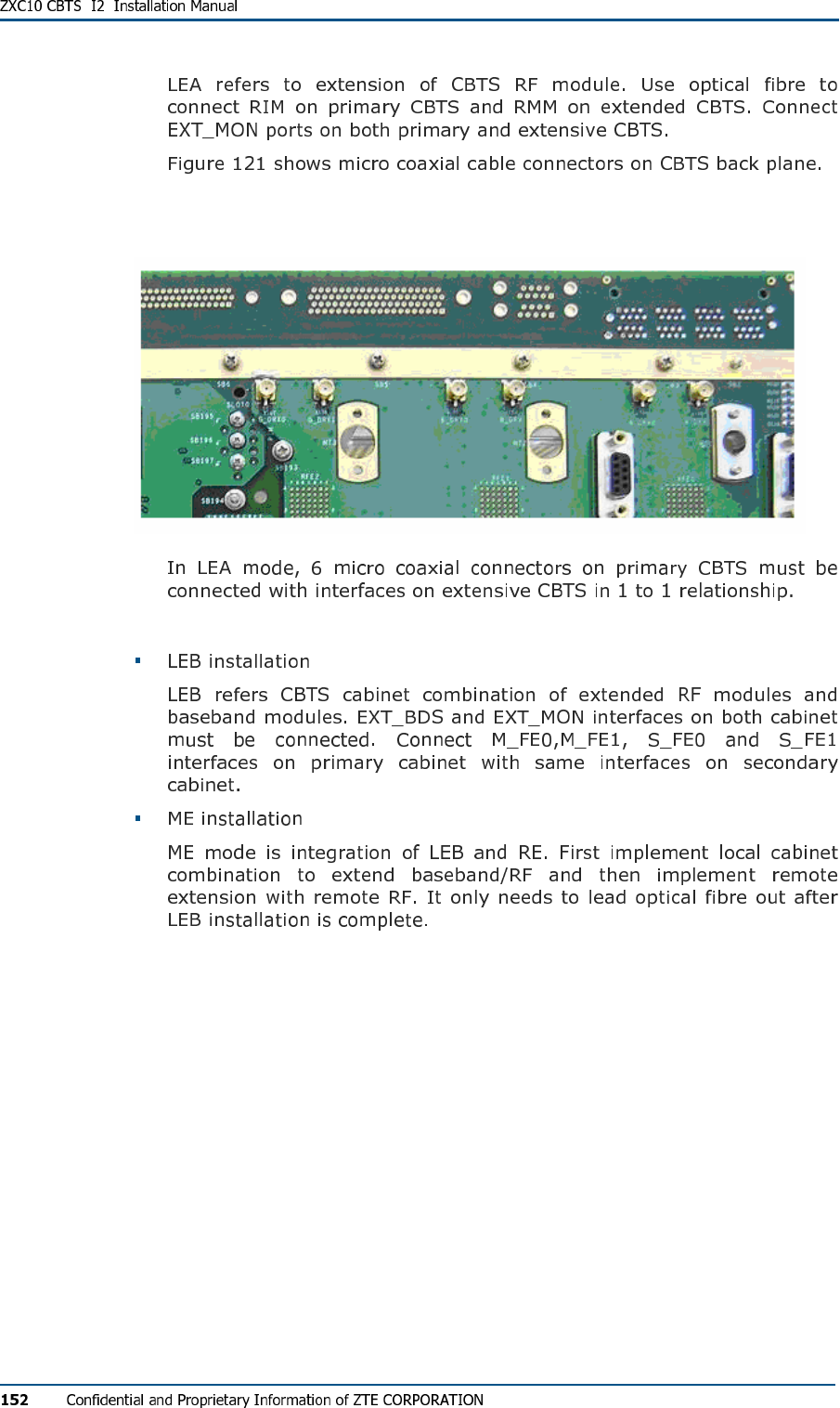
FIG U R E 121 - MICR O CO AXI AL CO N N E C T OR S
A p p e n d i x D
Monitoring Cables Definition
This section describes signal definition of four external monitoring
cables used in CBTS.
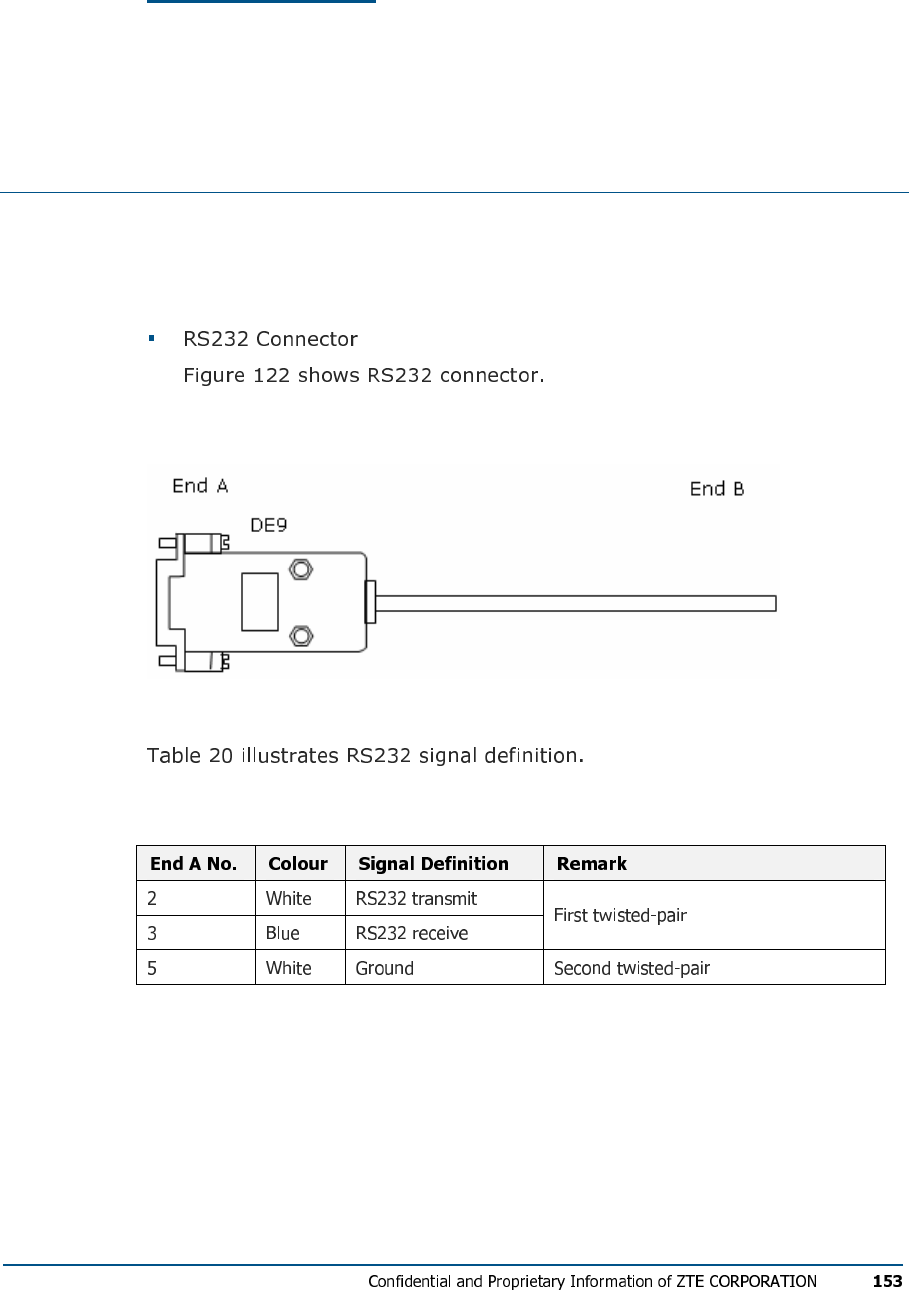
FIG U R E 122 - RS232 CO N N E C TO R
TABL E 20 - RS232 SI GN AL DE F I N I TI O N
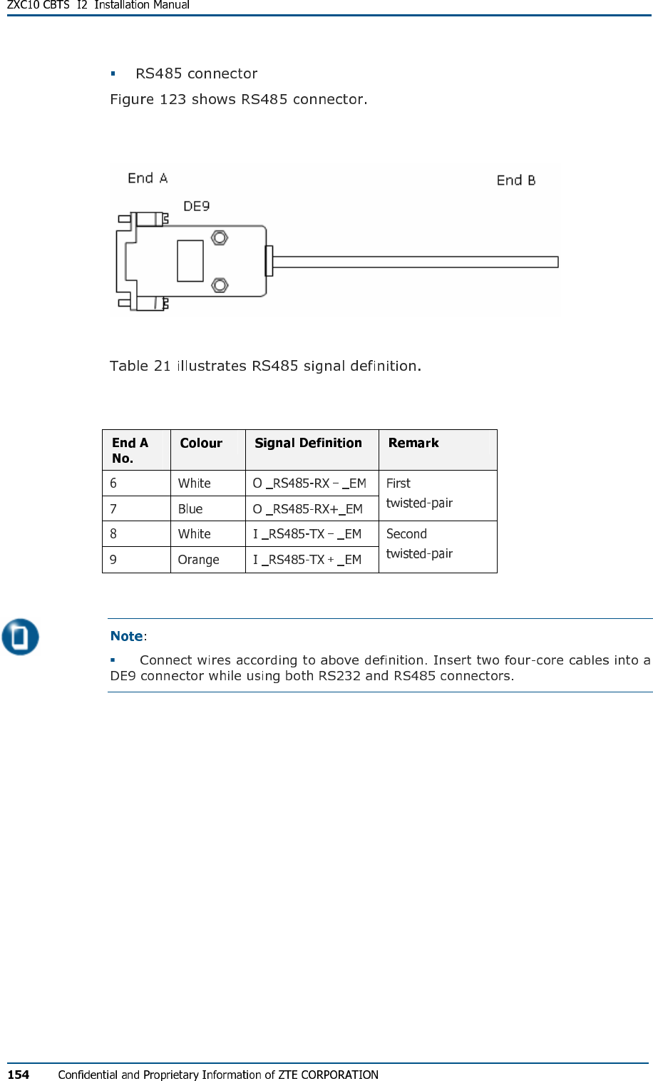
FIG U R E 123 - RS485 CO N N E C TO R
TABL E 21 - RS485 SI GN AL DE F I N I TI O N
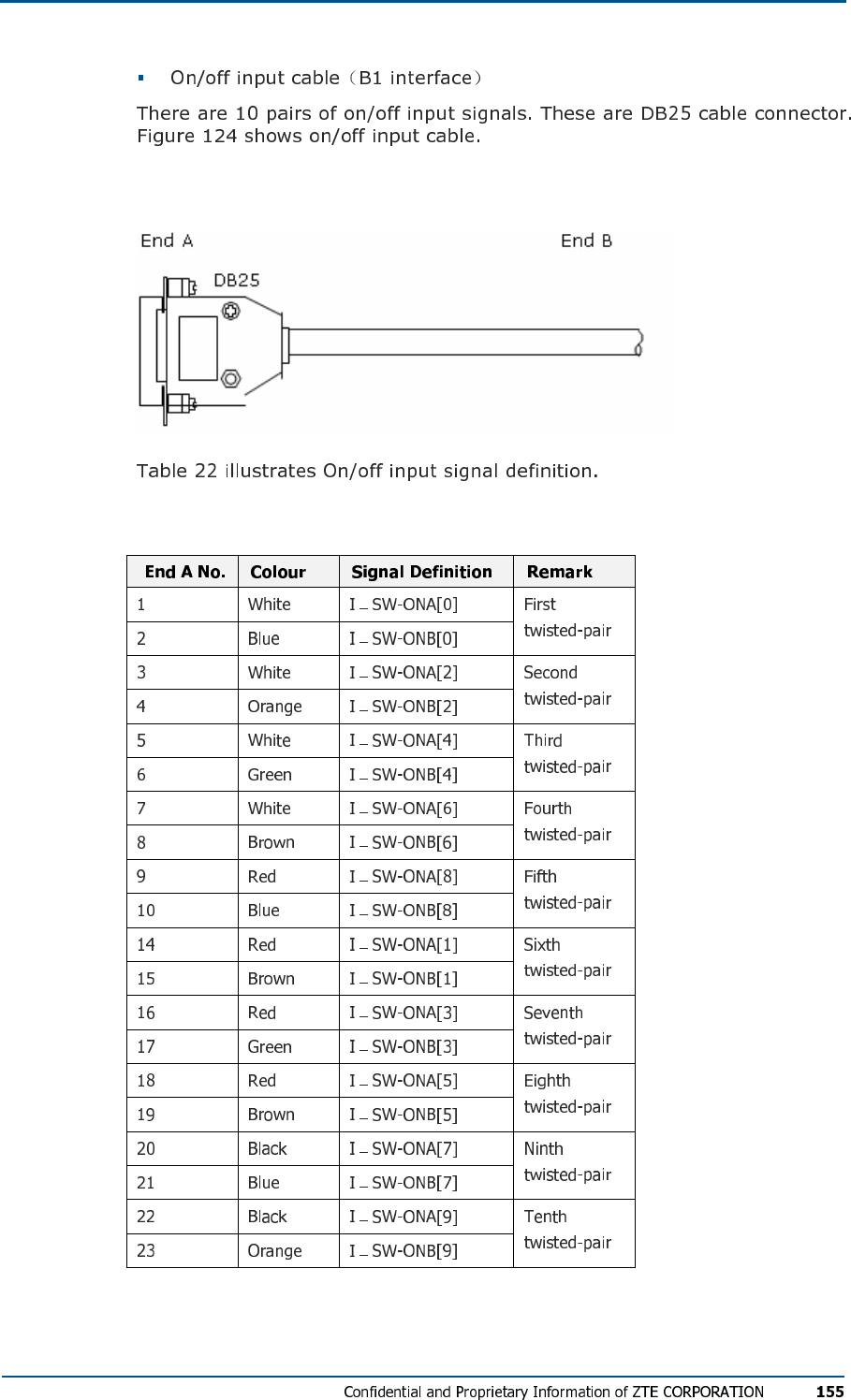
FIG U R E 124 - ON/OF F INP UT CA B L E
TABL E 22 - ON/OF F IN PU T SI GN AL DE F I NI T IO N
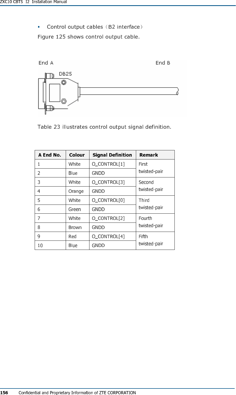
FIG U R E 125 - CON TR OL OU T P U T CA B LE
TABL E 23 - CO N TRO L OUTP U T SI GN AL DE F I N I T IO N
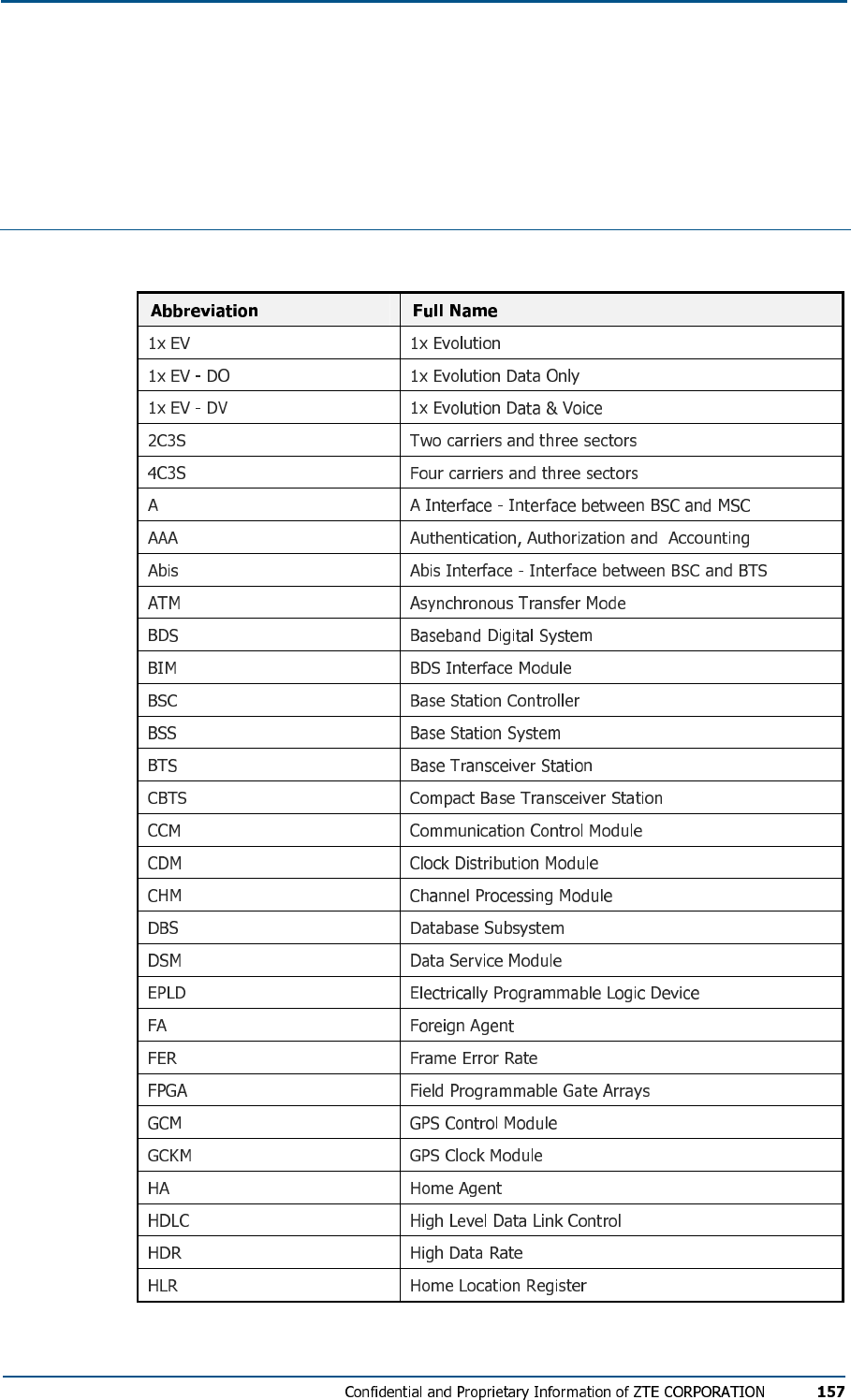
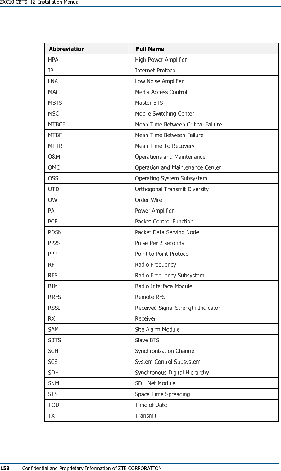
Acronyms
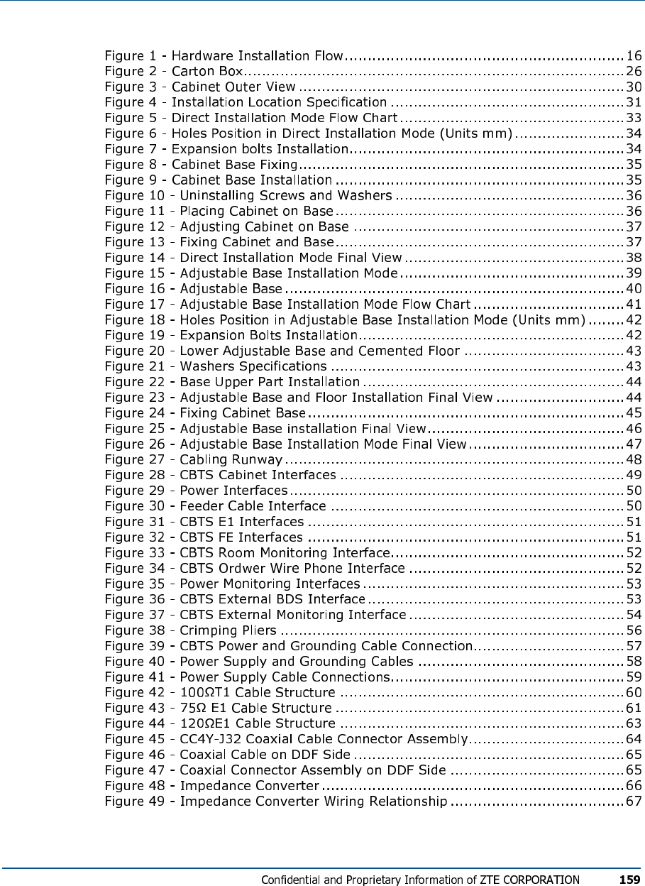
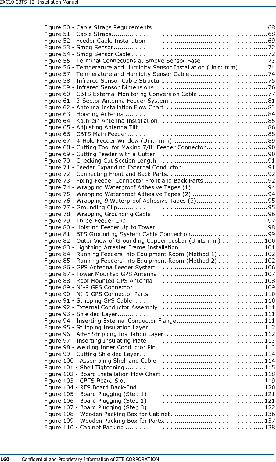
Figures
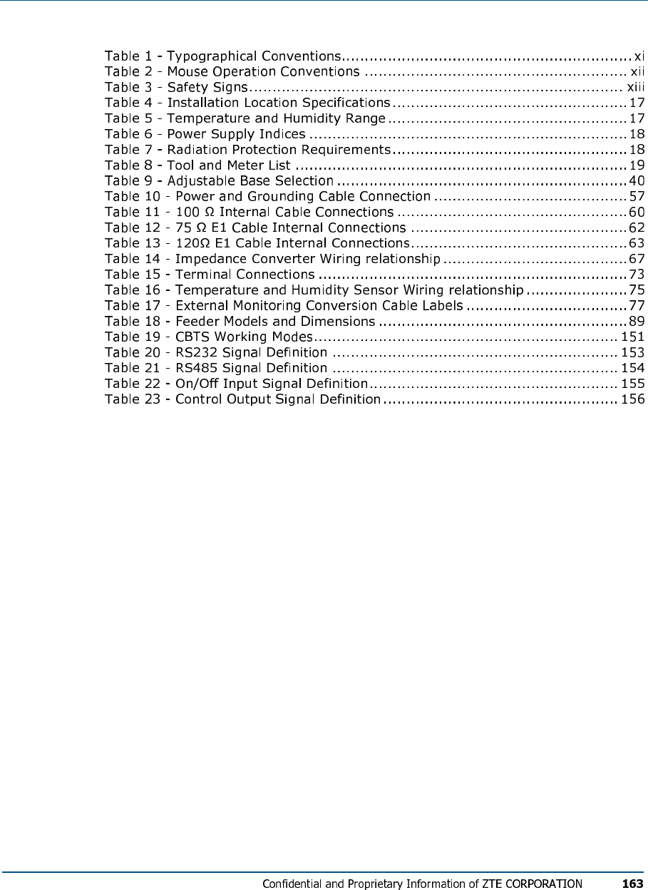
Tables

Index
4C3S 30 157
AAA 157
AC18 125 132 133
ANT1 93
ATM 157
B 39 60 61 62 63 72 73 74 75
147 151 153
BDS 29 52 53 117 121 157
BIM 157
BS18 20
BSC 19 21 50 60 62 63 157
BSS 80 157
BTS 53 99 100 157 158
CBTS1315 16 17 18 19 21 24
25 29 30 31 32 37 48 49 50
51 52 53 56 57 60 61 62 63
64 76 77 78 79 80 81 88 99
117 119 123 124 125 133 139
144 157
CC4Y-J32 64
CCM 157
CDMA2000 1 2
CHM 157
COM 52
DB50
DB25 72 137
DB44 51 53
DB9 52 74 76 137
DBS 157
DC18 100 132 133
DIN-F 101
DIN-M 101
DOOR 77
DOOR_MON 77
DSM 157
DUP 126
DV157
E1 3 27 125 148 149 150
E119 29 50 55 60 61 62 63 64
66 68 137
E1/T1 68
EPLD 157
EV157
EXT_MON 53
FA157
FE29 50 51
FER 157
FPGA 157
FREQ 148
GCM 157
GND 49 57 75
GPS 29 53 101 105 106 107 108
109 110 115 123 127 128 129
144 157
HA157
HDLC 157
HDR 157
HLR 157
INFORMATION 2
INFRARED 77
IP50 158
LEGAL 2
LNA 158
LOSS 148
MAC 158
MAIN 149 150
MASTER 20
MODE 149 150
MS20
MSC 157 158
MTBCF 158
MTBF 158
MTTR 158
N/A 3
O&M 158
OFF 132
OMC 158
OPEN 148
OSS 158
OTD 158
OUT 77
OW158
P13158
PA133 139 158
PCF 158
PDSN 158
PGND 49 100 125
PMM 133
PP2S 158
PPM 139 142
PPP 158
PRM 133
PWS 132 133
PWSB 52
R&D 3
R12
RF123 126 127 129 158
RFE 119 136 139 140 141 149
RFE-DIV 139
RFE-DUP 139
RFS 117 120 158
RIM 158
RJ11 51
ROOM 51 78
ROSENBERGER 90
RSSI 158
RX67 158
RX0 60 63
RX1 60 63
SAM 158
SCALE 149 150
SCH 158
SCS 158
SDH 158
SHORT 148
SITE 20
SMOG 77
SNM 158
STS 158
SWR 103 123 127 130 147 149 150
TEST 50
TOD 158
TRX 119 126 136 139 141
TX67 158
URL 1
V18 49 56 57 125 132 133 148
VGND 100
VSWR 19 130
ZXC10 13xi 16 18 21 31 61
Warning:
This device complies with part 15 of the FCC Rules. Operation is subject
to the following two conditions:
(1) This device may not cause harmful interference, and (2) this device must accept
any interference received, including interference that may cause undesired operation.
Changes or modifications to this unit not expressly approved by the
party responsible for compliance will void the user’s authority to
operate the equipment. Any change to the equipment will void FCC grant.
This equipment has been tested and found to comply with the limits
for a Class B digital device,pursuant to part 15 of the FCC Rules. These
limits are designed to provide reasonable protection against harmful
interference in a residential installation. This equipment generates,
uses and can radiate radio frequency energy and, if not installed
used in accordance with the instructions, may cause harmful interference
to radio communications. However, there is no guarantee that
interference will not occur in a particular installation. If this equipment
does cause harmful interference to radio or television reception, which
can be determined by turning the equipment off and on, the user is
encouraged to try to correct the interference by one or more of the
following measures:
--Reorient or relocate the receiving antenna.
--Increase the separation between the equipment and receiver.
--Connect the equipment into an outlet on a circuit different from that to which the
receiver is connected.
--Consult the dealer or an experienced radio/TV technician for help.
The equipment compliance with FCC radiation exposure limit set forth for
uncontrolled Environment