ZTE CBTSO18A CDMA2000 Outdoor Compact BTS-O1 User Manual
ZTE Corporation CDMA2000 Outdoor Compact BTS-O1 Users Manual
ZTE >
Users Manual

ZXC10 CBTS O1
CDMA2000 Outdoor Compact BTS - O1
Installation Manual
ZTE CORPORATION
ZTE Plaza, Keji Road South,
Hi-Tech Industrial Park,
Nanshan District, Shenzhen,
P. R. China
518057
Tel: (86) 755 26771900 800-9830-9830
Fax: (86) 755 26772236
URL: http://support.zte.com.cn
E-mail: doc@zte.com.cn

LEGAL INFORMATION
Copyright © 2005 ZTE CORPORATION.
The contents of this document are protected by copyright laws and international treaties. Any reproduction or distribution of
this document or any portion of this document, in any form by any means, without the prior written consent of ZTE
CORPORATION is prohibited. Additionally, the contents of this document are protected by contractual confidentiality
obligations.
All company, brand and product names are trade or service marks, or registered trade or service marks, of ZTE
CORPORATION or of their respective owners.
This document is provided “as is”, and all express, implied, or statutory warranties, representations or conditions are
disclaimed, including without limitation any implied warranty of merchantability, fitness for a particular purpose, title or non-
infringement. ZTE CORPORATION and its licensors shall not be liable for damages resulting from the use of or reliance on
the information contained herein.
ZTE CORPORATION or its licensors may have current or pending intellectual property rights or applications covering the
subject matter of this document. Except as expressly provided in any written license between ZTE CORPORATION and its
licensee, the user of this document shall not acquire any license to the subject matter herein.
The contents of this document and all policies of ZTE CORPORATION, including without limitation policies related to support
or training are subject to change without notice.
Revision History
Date Revision No. Serial No. Description
04/18/2006 R1.XX S.N (sjzlyyyyxxxx) CDMA2000 Outdoor Compact BTS- O1 - English Contents

ZTE CORPORATION
Values Your Comments & Suggestions!
Your opinion is of great value and will help us improve the quality of our
product documentation and offer better services to our customers.
Please fax to: (86) 755-26772236; or mail to Publications R&D
Department, ZTE CORPORATION, ZTE Plaza, A Wing, Keji Road South,
Hi-Tech Industrial Park, Shenzhen, P. R. China 518057.
Thank you for your cooperation!
Document
Name ZXC10 CBTS O1 CDMA2000 Outdoor Compact BTS - O1
Product
Version Document
Revision Number
Equipment Installation Date
Presentation:
(Introductions, Procedures, Illustrations, Completeness, Level of Detail, Organization,
Appearance)
Good Fair Average Poor Bad N/A
Accessibility:
(Contents, Index, Headings, Numbering, Glossary)
Good Fair Average Poor Bad N/A
Your evaluation
of this
documentation
Intelligibility:
(Language, Vocabulary, Readability & Clarity, Technical Accuracy, Content)
Good Fair Average Poor Bad N/A
Your
suggestions for
improvement
of this
documentation
Please check the suggestions which you feel can improve this documentation:
Improve the overview/introduction Make it more concise/brief
Improve the Contents Add more step-by-step procedures/tutorials
Improve the organization Add more troubleshooting information
Include more figures Make it less technical Add more examples
Add more/better quick reference aids Add more detail Improve the index
Other suggestions
___________________________________________________________________________
___________________________________________________________________________
___________________________________________________________________________
___________________________________________________________________________
___________________________________________________________________________
# Please feel free to write any comments on an attached sheet.
If you wish to be contacted regarding your comments, please complete the following:
Name Company
Postcode Address
Telephone E-mail
This page is intentionally blank.

Contents
About this Manual .....................................................................................xi
Purpose of this Manual ........................................................................................... xi
Typographical Conventions..................................................................................... xi
Mouse Operation Conventions.................................................................................xii
Safety Signs.........................................................................................................xiii
How to Get in Touch .............................................................................................xiv
Customer Support ................................................................................................................xiv
Documentation Support........................................................................................................ xiv
Chapter 1 ...................................................................................... 15
Installation Preparation.......................................................................... 15
Hardware Installation Flow .................................................................................... 16
CBTS O1 Installation Precautions ........................................................................... 17
Environment Inspections ....................................................................................... 17
Installation Location Specifications ......................................................................................... 17
Temperature and Humidity Range.......................................................................................... 17
Power Supply Requirements .................................................................................................. 18
Power Consumption Requirements......................................................................................... 18
Electromagnetic Radiation Protection...................................................................................... 19
Antenna Feeder System Requirements................................................................................... 19
Other Requirements ..............................................................................................................19
Tool and Meter List for Installation.......................................................................... 20
Technical Documentation Preparation..................................................................... 22
Project Commissioning Documents ........................................................................................ 22
Acceptance Reports ...............................................................................................................22
Reference Documents ........................................................................................................... 22
Chapter 2 ...................................................................................... 23
Unpacking and Handover........................................................................ 23
Checking Equipment List ....................................................................................... 24
Unpacking Wooden Box ........................................................................................ 25
Wooden Box Structure...........................................................................................................25
Unpacking Procedure.............................................................................................................25
Checking Cabinet ..................................................................................................................26
Unpacking Carton ................................................................................................. 26
Carton Structure ...................................................................................................................26
Unpacking Procedure.............................................................................................................26
Unpacking Precautions...........................................................................................................27
Checking Boards ...................................................................................................................27
Acceptance and Handover ..................................................................................... 27
Chapter 3 ...................................................................................... 29
Cabinet Installation................................................................................. 29
Cabinet Structure ................................................................................................. 30
Cabinet Installation Precautions.............................................................................................. 32
Ground Installation Mode ...................................................................................... 32
Ground Installation Mode Flow ............................................................................................... 33
Cabinet Accessories Installation ............................................................................. 39
Heat Exchanger.....................................................................................................................39
Shutter .................................................................................................................................40
Power Subrack ...................................................................................................................... 41
Windshield Cover Board.........................................................................................................42
Chapter 4 ...................................................................................... 45
Cable Installation .................................................................................... 45
Power and Grounding Cables ................................................................................. 46
Power Cable Installation ........................................................................................ 46
External Cable Installation ..................................................................................... 48
Antenna Feeder RF Cable.......................................................................................................50
Battery Cables.......................................................................................................................51
Optical Cable & Microwave Intermediate Frequency Cable ....................................................... 51
E1/T1 Cable ..........................................................................................................................52
Cable Installation Requirements ............................................................................................. 53
Chapter 5 ...................................................................................... 55
Main Antenna Feeder System Installation ............................................. 55
Main Antenna Feeder System Installation ............................................................... 56
Antenna Installation Preparation ............................................................................................56
Antenna Installation Precautions ............................................................................................ 56
Main Antenna Feeder System Structure.................................................................................. 56
Antennas Types ....................................................................................................................58
Super Flexible Jumper ...........................................................................................................58
Main Feeder Cable.................................................................................................................59
Grounding Kit........................................................................................................................ 59
Lightning Arrester..................................................................................................................60
Antenna Feeder System Connectors....................................................................................... 61
Antenna Installation Technical Parameters..............................................................................63
Antenna Installation Flow Chart.............................................................................................. 64
Selecting Installation Position .................................................................................................64
Moving and Hoisting Antenna.................................................................................................64
Uni-Directional Antenna Installation........................................................................................ 66
Omni-Directional Antenna Installation .................................................................................... 70
Main Feeder Installation.........................................................................................................71
Antenna Jumpers Installation ................................................................................................. 72
Feeder Cable Installation........................................................................................................73
Lightning Arrester Installation ................................................................................................75
Grounding Kit Installation ......................................................................................................77
Cabinet Jumper Installation....................................................................................................79
Testing Antenna Feeder System............................................................................................. 79
Waterproofing Connectors ..................................................................................................... 80
Chapter 6 ...................................................................................... 81
GPS Antenna Feeder System Installation .............................................. 81
GPS Antenna Feeder System Structure................................................................... 82
Installation Position and Requirements ................................................................... 83
Installation Requirements ......................................................................................................84
Lightning Protection Requirements ......................................................................................... 85
NJ-9 Connector Preparation ................................................................................... 85
NJ-9 Connector .....................................................................................................................85
Connector Preparation Procedure ........................................................................................... 86
GPS Connector Installation Check ..........................................................................................91
Chapter 7 ...................................................................................... 93
Board Installation ................................................................................... 93
Installation Flow Chart .......................................................................................... 94
Installation Procedure and Precautions ................................................................... 95
Installation Precautions.......................................................................................................... 95
CBTS O1 Board Slot ..............................................................................................................95
RFS Board Installation ...........................................................................................................96
BDS Board Installation...........................................................................................................96
Chapter 8 ...................................................................................... 99
Hardware Installation Check .................................................................. 99
Cabinet Installation Check ................................................................................... 100
Cabling Rack Installation Check ........................................................................... 100
Cable Installation Check ...................................................................................... 101
Power and Grounding Cables ............................................................................................... 101
Trunk and RF Cables ........................................................................................................... 102
Board and Sensor Installation Check .................................................................... 102
Antenna and GPS Feeder System Installation Check .............................................. 103
1/2” Indoor Jumper ............................................................................................................. 103
Lightning arrester ................................................................................................................ 103
Main GPS Feeder ................................................................................................................. 103
Three – Way Feeder Clamp.................................................................................................. 104
1/2” Outdoor Jumper........................................................................................................... 104
Antenna.............................................................................................................................. 105
Feeder SWR ........................................................................................................................ 105
Environment Check............................................................................................. 106
Chapter 9 .................................................................................... 107
Power On and Off Mechanism .............................................................. 107
Power Supply Inspection ..................................................................................... 108
Precautions ........................................................................................................ 108
Power-on Procedure............................................................................................ 108
Power-off Procedure............................................................................................ 109
Appendix A ................................................................................. 111
Packing, Storage and Transportation................................................... 111
Packaging .......................................................................................................... 112
Cabinet packing .................................................................................................................. 112
Cabinet Packing Procedure................................................................................................... 113
Board Packing ..................................................................................................................... 115
Board packing procedure ..................................................................................................... 115
Base Packing....................................................................................................................... 118
Engineering Materials Packing .............................................................................................. 118
Transportation.................................................................................................... 119
Storage ............................................................................................................. 119
Appendix B ................................................................................. 121
SiteMaster Usage................................................................................... 121
Frequency Range Selection.................................................................................. 122
SiteMaster Check................................................................................................ 122
Feeder Input Parameters..................................................................................... 122
Tester Installation............................................................................................... 123
Measuring SWR .................................................................................................. 123
Measuring DTF ................................................................................................... 124
Acronyms ................................................................................... 125
Figures........................................................................................ 127
Tables ......................................................................................... 129
Index .......................................................................................... 131
This page is intentionally blank.

Confidential and Proprietary Information of ZTE CORPORATION xi
About this Manual
Purpose of this Manual
This manual describes ZXC10 Outdoor Compact Base Transceiver Station
O1 hardware installation.
Typographical Conventions
ZTE documents employ the following typographical conventions.
TABLE 1 - TYPOGRAPHICAL CONVENTIONS
Typeface Meaning
Italics
References to other guides and documents.
“Quotes” Links on screens.
Bold Menus, menu options, input fields, radio button names, check
boxes, drop-down lists, dialog box names, window names
Bold, with first
letter capitalized
Keys on the keyboard and buttons on screens
Constant width Text that you type, program code, files and directory names,
and function names
[ ] Optional parameters
{ } Mandatory parameters
| Select one of the parameters that are delimited by it
Note: Provides additional information about a certain topic.
Checkpoint: Indicates that a particular step needs to be checked
before proceeding further.
Tip: Indicates a suggestion or hint to make things easier or
more productive for the reader.

ZXC10 CBTS O1 Hardware Installation Manual
xii Confidential and Proprietary Information of ZTE CORPORATION
Mouse Operation Conventions
TABLE 2 - MOUSE OPERATION CONVENTIONS
Typeface Meaning
Click Refers to clicking the primary mouse button (usually the left
mouse button) once.
Double-click Refers to quickly clicking the primary mouse button (usually the
left mouse button) twice.
Right-click Refers to clicking the secondary mouse button (usually the right
mouse button) once.
Drag Refers to pressing and holding a mouse button and moving the
mouse.
About this Manual
Confidential and Proprietary Information of ZTE CORPORATION xiii
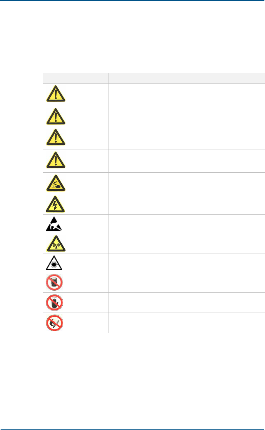
Safety Signs
TABLE 3 - SAFETY SIGNS
Safety Signs Meaning
Danger: Indicates an imminently hazardous situation, which if
not avoided, will result in death or serious injury. This signal
word should be limited to only extreme situations.
Warning: Indicates a potentially hazardous situation, which if
not avoided, could result in death or serious injury.
Caution: Indicates a potentially hazardous situation, which if not
avoided, could result in minor or moderate injury. It may also
be used to alert against unsafe practices.
Note: Indicates a potentially hazardous situation, which if not
avoided, could result in injuries, equipment damage or
interruption of services.
Erosion: Beware of erosion.
Electric shock: There is a risk of electric shock.
Electrostatic: The device may be sensitive to static electricity.
Microwave: Beware of strong electromagnetic field.
Laser: Beware of strong laser beam.
No flammables: No flammables can be stored.
No touching: Do not touch.
No smoking: Smoking is forbidden.

ZXC10 CBTS O1 Hardware Installation Manual
xiv Confidential and Proprietary Information of ZTE CORPORATION
How to Get in Touch
The following section provides information on how to obtain support for
the documentation and the software.
Customer Support
If you have problems, questions, comments, or suggestions regarding
your product, contact us by e-mail at support@zte.com.cn. You can also
call our customer support center at (86) 755 26771900 and (86) 800-
9830-9830.
Documentation Support
ZTE welcomes your comments and suggestions on the quality and
usefulness of this document. For further questions, comments, or
suggestions on the documentation, you can contact us by e-mail at
doc@zte.com.cn; or you can fax your comments and suggestions to (86)
755 26772236. You can also explore our website at
http://support.zte.com.cn, which contains various interesting subjects like
documentation, knowledge base, forum and service request.
FCC STATEMENT
Before using this CDMA ZXC10 CBTS I28A and CBTS I219, read this
important RF energy awareness and control information and operational
instructions to ensure compliance with the FCC RF exposure guidelines.
NOTICE: Working with the equipment while in operation, may expose the
technician to RF electromagnetic fields that exceed FCC rules for human
exposure. Visit the FCC website at www.fcc.gov/oet/rfsafety to learn more
about the effects of exposure to RF electromagnetic fields.
Changes or modifications to this unit not expressly approved by the party
responsible for compliance will void the user’s authority to operate the
equipment. Any change to the equipment will void FCC grant.
This equipment has been tested and found to comply with the limits for a
Class A digital device, pursuant to the FCC Rules. This equipment
generates, uses and can radiate radio frequency energy and, if not
installed and used in accordance with the instructions, may cause harmful
interference to radio communications. However, there is no guarantee that
interference will not occur in a particular installation.

Confidential and Proprietary Information of ZTE CORPORATION 15
Chapter 1
Installation Preparation
This chapter describes:
Hardware installation flow
CBTS O1 installation precautions
Environment inspections
Installation location specifications
Temperature and humidity requirements
Power supply requirements
Power consumption requirements
Electromagnetic radiation protection
Antenna feeder system requirements
Other requirements
Tool and meter list for installation
Technical documentation preparation
Project commissioning documents
Acceptance reports
Reference documents
ZXC10 CBTS O1 Hardware Installation Manual
16 Confidential and Proprietary Information of ZTE CORPORATION
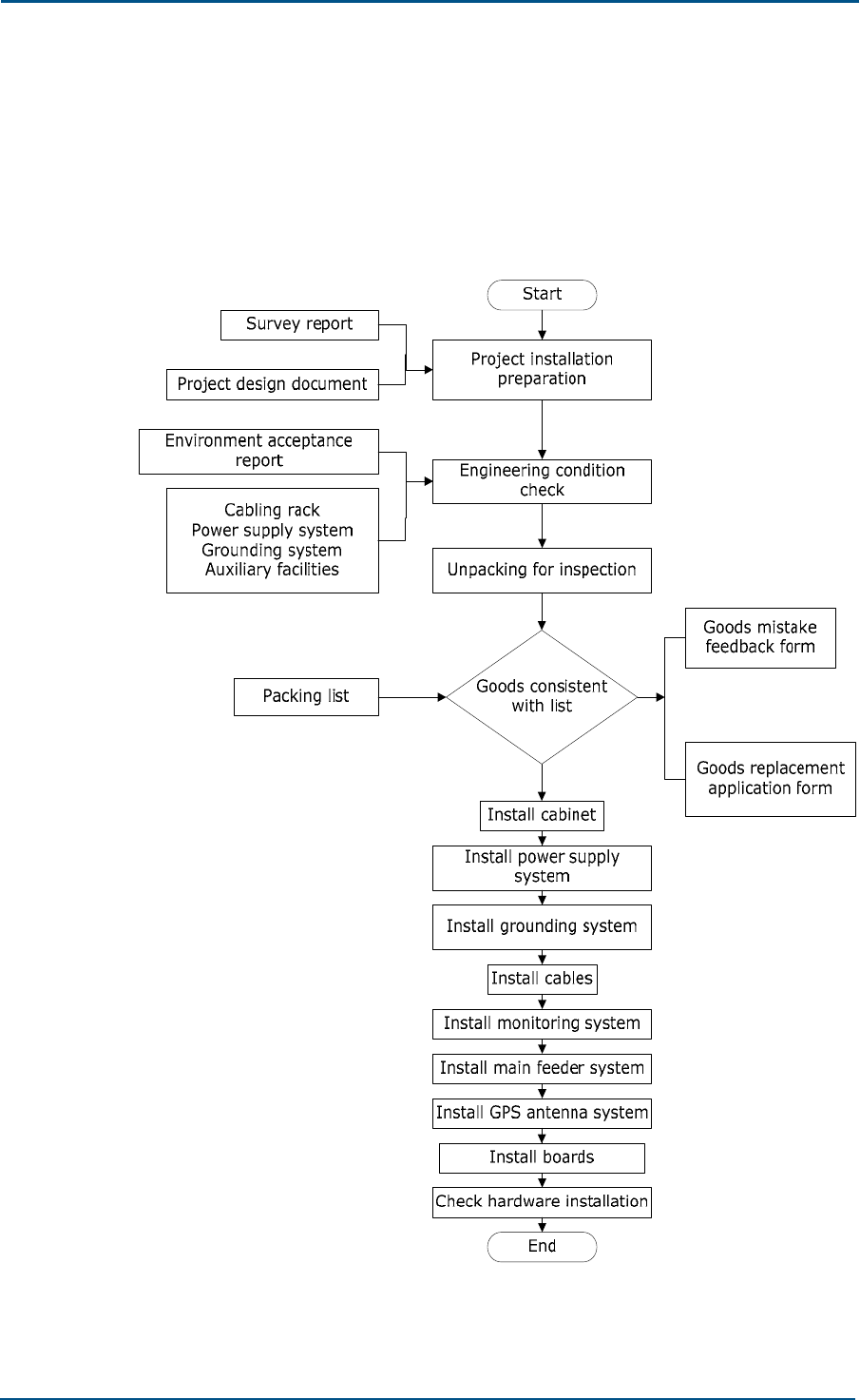
Hardware Installation Flow
Figure 1 shows ZXC10 Compact BTS (CBTS O1) hardware installation flow.
FIGURE 1 - HARDWARE INSTALLATION FLOW

Chapter 1 - Installation Preparation
Confidential and Proprietary Information of ZTE CORPORATION 17
CBTS O1 Installation Precautions
Take following precautions during CBTS O1 installation.
Avoid hot swap during board installation.
Never install antenna feeder system in case of lightning.
Check that lightening arresters are in proper contact. Replace damaged
arresters immediately.
Wear antistatic wrist strap during installation.
Only qualified person should do installation.
Follow specific manual provided by ZTE for installation.
Environment Inspections
Before installation, the operator should finalize and prepare installation
location, arrange power supply and grounding cables, and provide
necessary facilities for installation.
Installation Location Specifications
Installation location must fulfill the engineering requirements. Table 4 lists
equipment room basic requirements.
TABLE 4 - INSTALLATION LOCATION SPECIFICATIONS
Item Requirements
Grounding Install lightning arrester and proper grounding equipment to avoid any
damage due to short circuits
Temperature and Humidity Range
Table 5 shows CBTS O1 temperature and humidity range.
TABLE 5 - TEMPERATURE AND HUMIDITY RANGE
Item Working range Recommended range
Temperature -40 °C ~ +55 °C +15 °C ~ +35 °C
Humidity 5% RH ~ 98% RH 40% RH ~ 60% RH

ZXC10 CBTS O1 Hardware Installation Manual
18 Confidential and Proprietary Information of ZTE CORPORATION
Power Supply Requirements
Table 6 and Table 7 illustrate ZXC10 CBTS O1 power supply and power
consumption requirements respectively.
TABLE 6 - POWER SUPPLY INDICES
Indices Name Index Requirements
Power system
range -48 V power supply in range of -43.2 V ~ -56.5 V
Power noise level Satisfies Ministry of Post and Telecom technical
specifications
DC power
supply
Power protection Includes Over-voltage/Over-current protection and
indication
220 V power supply in range of 130 V ~ 300 V
Power system
range 110 V power supply in range of 90 V ~ 140 V
Not included now, but under consider for future
Power noise level Satisfies Ministry of Post and Telecom technical
specifications
Power protection Includes Over-voltage/Over-current protection and
indication
AC power
supply
Frequency range Supports frequency range from 45 Hz ~ 65 Hz.
Recommended frequency is 50 Hz.
Note:
DC power is supplied with battery group (UPS). There is no direct DC supply.
Power Consumption Requirements
TABLE 7 - POWER CONSUMPTION REQUIREMENTS
System Description Power consumption (W) Remarks
Main equipment with full
configuration
2000 Power amplifier’s power
consumption is 60 W
Heater 2400
Total 4400
Note:
To configure a storage battery group, calculate corresponding power
consumption according to storage battery group capability. It is recommended to
configure 200 AH or 400 AH storage battery group. Former can supply power
continuously for 4 hours, and latter can supply 8 hours. During charging, 400 AH
storage battery group power consumption is about 2000W.

Chapter 1 - Installation Preparation
Confidential and Proprietary Information of ZTE CORPORATION 19
Electromagnetic Radiation Protection
Ensure following Electromagnetic Radiation Protection Requirements. Table
8 shows electromagnetic radiation protection requirements.
TABLE 8 - RADIATION PROTECTION REQUIREMENTS
Item Requirements
Public exposure In 24 hours of a day, average value of electromagnetic power density
(in six consecutive minutes) < 0.4 W/m2 (30 MHz ~ 3000 MHz)
Professional
radiation
In 8 hours of a day, average value of electromagnetic power density (in
six consecutive minutes) < 2 W/m2 (30 MHz ~ 3000 MHz)
Antenna Feeder System Requirements
Check whether following items comply with CBTS O1 requirements and
project design.
Height and dimensions of feeder window
Height, weight bearing and grounding of outdoor cable rack
Height, weight bearing and grounding of indoor cable rack
Height, diameter, weight bearing, wind resisting, grounding, lightning
protection, and direction of antenna installation pole of building BS
Height, diameter, weight bearing, wind resisting, grounding, lightning
protection, and direction of antenna installation pole of iron tower BS
Other Requirements
According to contract, check whether following requirements are fulfilled:
Cables for external power supply and cabinet are available
E1 cable connecting CBTS O1 and BSC is present
Fire extinguisher is available
CBTS O1 cabinet mechanical intensity meets the requirement of ETSI
300 019-2-4 class 4M3
Atmospheric pressure is in the range of 70 kPa ~ 106 kPa
Wind resistance should not be less than 200 km/h
Cabinet temperature variation must be less than 1° C/min
Cabinet must be resistant to all atmospheric conditions like: rain, dust,
moisture. It must comply with IP protection level of IP55
CBTS O1 does not have internal transmission equipments such as SDH
equipments and microwave equipments which must be supplied
according requirements

ZXC10 CBTS O1 Hardware Installation Manual
20 Confidential and Proprietary Information of ZTE CORPORATION
Tool and Meter List for Installation
Table 9 shows tools and meters list required during installation.
TABLE 9 - TOOL AND METER LIST
Category Name
Special-purpose tools
One feeder connector knife
One wire stripper for 75 Ω coaxial cables
One crimping pliers for 75 Ω coaxial cables
One multi-functional crimping pliers
One multimeter
One SiteMaster VSWR tester
Earth resistance tester
Concrete drilling tools
One electric percussion drill
Auxiliary and sample bits
One vacuum cleaner
Power socket (two-phase and three-phase socket, with current
capacity greater than 15 A)
General-purpose tools
Cross screwdrivers (4”, 6” and 8” each)
Flathead screwdrivers (4”, 6” and 8” each)
Adjustable wrenches (6’, 8’, 10’ and 12’)
Dual-purpose spanners (17” and 19” each)
One set of socket wrench
11.02 lb (5 kg) nail hammer
One 300 W iron
One 40 W iron
Solder wires
Measurement tools
One 50 m tape measure
One 5 m steel tape
One 400 mm level bar
One angle meter
One compass
Plumb
Protection tools
Antistatic wrist strap
Safety helmet
Pair of gloves

Chapter 1 - Installation Preparation
Confidential and Proprietary Information of ZTE CORPORATION 21
Category Name
Small tools
One hacksaw (with several saw blades)
One pair of sharp-nose pliers (8”)
One pair of diagonal pliers (8”)
One pair of slip joint pliers (8")
One pair of vices (8”)
One needle file set (medium sized)
Tweezers
One paintbrush
One pair of scissors
One hot blower
One solder sucker
One pair of hydraulic pliers
Crowbar
Auxiliary tools
Pulley block
Rope
Ladder
Forklift
Meter
Spectrum analyzer
SITE MASTER BS tester
Qualcomm test MS
Compass
Multimeter
Field strength tester
Note:
Do not use meters unless they are strictly calibrated and proven qualified.

ZXC10 CBTS O1 Hardware Installation Manual
22 Confidential and Proprietary Information of ZTE CORPORATION
Technical Documentation
Preparation
Project Commissioning Documents
Prepare following technical documents for equipment commissioning
Project Survey Report
Engineering staff should prepare a Project Survey Report during onsite
survey.
Engineering design documents
Engineering design documents should be completed by designing unit
that the subscriber entrusts. Its replication copy should be provided to
the equipment provider before equipment delivery.
Environment Acceptance Report
Environment Acceptance Report is used for first environment
acceptance in BSC survey, showing whether CBTS O1 installation
requirements are satisfied. If installation environment is not
appropriate, the customer should improve the conditions and solve the
problems. Conduct second environment inspection before the
engineering starts.
Acceptance Reports
Installation Acceptance Report and Test Acceptance Report are post
commissioning acceptance documents. The equipment supplier provides
these documents to the customer at delivery time. The installation staff
should complete these documents in presence of the customer after CBTS
O1 system commissioning.
Reference Documents
Use following manuals for reference during installation:
ZXC10 Outdoor Compact BTS O1 Technical Manual
ZXC10 Outdoor Compact BTS O1 Hardware Manual
ZXC10 Outdoor Compact BTS O1 Hardware Installation Manual

Confidential and Proprietary Information of ZTE CORPORATION 23
Chapter 2
Unpacking and Handover
This chapter describes:
Checking equipment list
Unpacking wooden case
Wooden case structure
Unpacking procedure
Checking cabinet
Unpacking carton
Carton structure
Unpacking procedure
Unpacking precautions
Checking boards
Acceptance and handover

ZXC10 CBTS O1 Hardware Installation Manual
24 Confidential and Proprietary Information of ZTE CORPORATION
Checking Equipment List
Count goods during unpacking and note following points:
Check Delivery Checklist of ZTE CORPORATION.
Check total number of goods, intactness of packing boxes, and check
whether arrival place is actual installation place against packing list
number attached to packing boxes.
If goods are intact, start to unpack and inspect them.
Contact ZTE headquarters, if any item is damaged or missing during
unpacking inspection process.
Use appropriate tools to open cartons to avoid any equipment damage.
Note:
Handle CBTS O1 equipment with care and protect it from direct sunlight and
rain.
Count goods against attached list and keep a record.
Chapter 2 - Unpacking and Handover
Confidential and Proprietary Information of ZTE CORPORATION 25
Unpacking Wooden Box
Wooden Box Structure
Figure 2 shows CBTS O1 cabinet wooden box structure.
FIGURE 2 - WOODEN BOX
Unpacking Procedure
Take following steps to unpack a wooden box:
1. Arrange appropriate tools such as nail hammer, pliers, straight
screwdriver and crowbar.
2. Insert a flat-tip screwdriver into slit between case and front cover
board to make it loose. Then insert a crowbar to unclench cover board.
3. Erect wooden case. Make sure that supports are at the bottom and pull
cabinet out from case gently.
4. Remove packing adhesive cabinet tape.
Note:
Handle CBTS O1 cabinet with care during movement to avoid damage.

ZXC10 CBTS O1 Hardware Installation Manual
26 Confidential and Proprietary Information of ZTE CORPORATION
Checking Cabinet
Check cabinet according to packing list and ensure following:
There are no dents, bulges, scratches, peels, blithers, blisters or
smudges on outer surface of cabinets.
Busbars, fans and installation positions on cabinets are free from
damage or distortion.
Cabinet slots for plug-in frames are intact. Guide rails of plug-in slots
are not damaged.
Installation slot labels are intact.
Fastening screws are not loosen, disconnected, or mistakenly placed.
Accessories and fittings needed for cabinet installation are complete.
Unpacking Carton
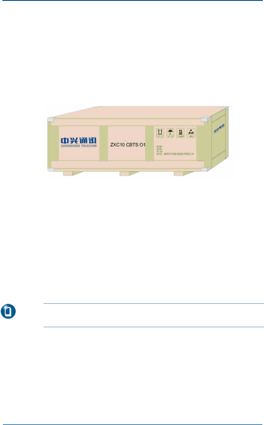
Carton Structure
Figure 3 shows carton box structure.
FIGURE 3 - CARTON BOX
ZXC10 CBTS O1
Unpacking Procedure
Take following steps to unpack a carton:
1. Use diagonal pliers to cut packing straps.
2. Use a paper knife to cut adhesive tape along slits on carton covers.

Chapter 2 - Unpacking and Handover
Confidential and Proprietary Information of ZTE CORPORATION 27
Unpacking Precautions
Take following precautions to unpack carton:
Take anti-static measures to avoid equipment damage.
To avoid damage to goods, do not cut too deep.
Wait for 30 minutes before unpacking equipment, when equipment is
moved from a colder and drier place to a hotter and damper place.
Properly recycle desiccants.
Checking Boards
Check quality, quantity, type, cracks and model of all boards inside carton
against packing list provided by ZTE office.
Acceptance and Handover
Upon completion of unpacking, representative of customer and project
supervisor should sign Unpacking for Inspection Report to acknowledge
acceptance. Each party should have a copy of Unpacking for Inspection
Report.

ZXC10 CBTS O1 Hardware Installation Manual
28 Confidential and Proprietary Information of ZTE CORPORATION
This page is intentionally blank

Confidential and Proprietary Information of ZTE CORPORATION 29
Chapter 3
Cabinet Installation
This chapter describes:
Cabinet structure
Cabinet installation precautions
Ground installation mode
Ground installation mode flow
ZXC10 CBTS O1 Hardware Installation Manual
30 Confidential and Proprietary Information of ZTE CORPORATION
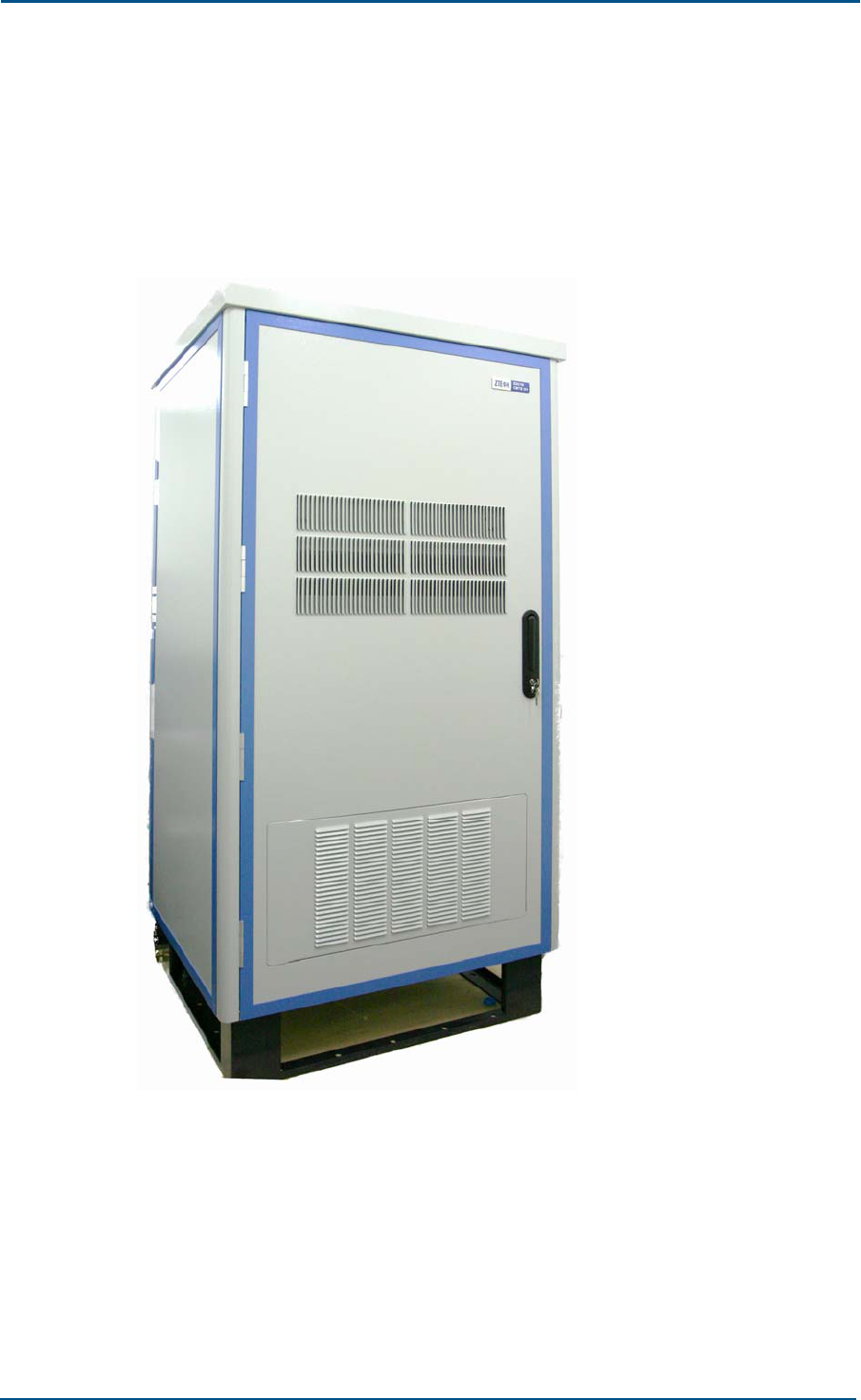
Cabinet Structure
FIGURE 4 - CABINET OUTER VIEW
Figure 4 shows CBTS O1 cabinet outer view.
Cabinet dimensions: 900 mm (W) × 780 mm (D) × 1800 mm (H)
Cabinet dimensions: 35.43 inch (W) × 30.70 inch (D) × 70.86 inch (H)
Chapter 3 - Cabinet Installation
Confidential and Proprietary Information of ZTE CORPORATION 31
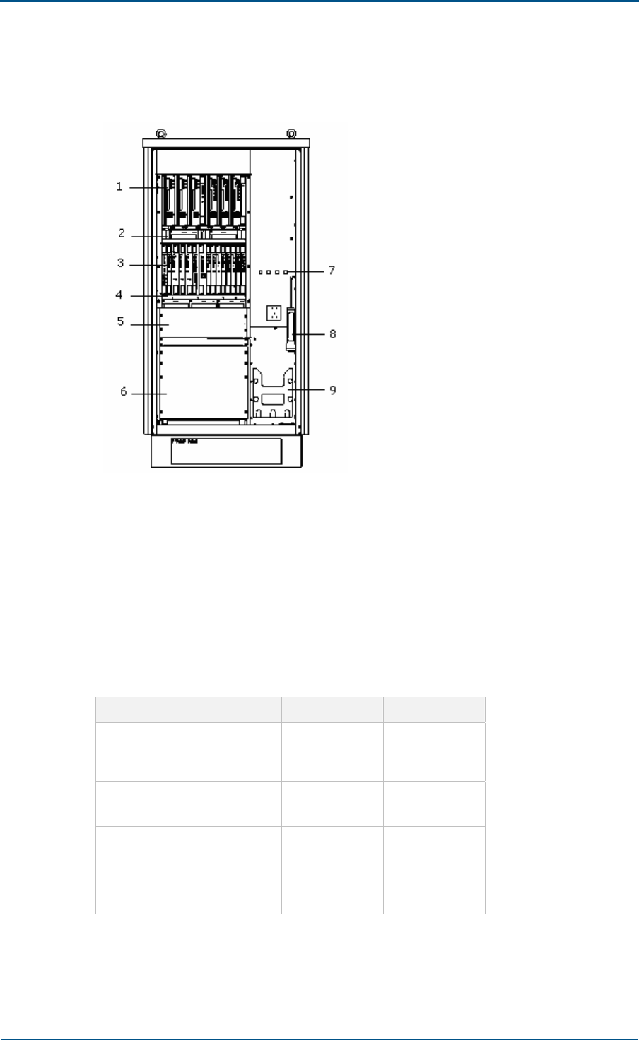
Figure 5 shows CBTS O1 cabinet front view.
FIGURE 5 - CABINET FRONT VIEW
1. Upper shelf 2. Fan group 1
3. Lower shelf 4. Fan group 2
5. Transmission shelf 6. Power shelf
7. Test port and O_PH 8. Flashlight
9. Battery group
Table 10 illustrates CBTS O1 weights with different configurations.
TABLE 10 - CABINET WEIGHT
System Description Weight (lb)Weight (kg)
Cabinet (including a heat
exchanger, rack and base)
562.17 255
Imbedded power module
55.11 25
4C1S modules
70.54 32
4C3S modules
134.48 61

ZXC10 CBTS O1 Hardware Installation Manual
32 Confidential and Proprietary Information of ZTE CORPORATION
Cabinet Installation Precautions
Install cabinet according to engineering design specifications.
Vertical error should be less than 0.118 inch (0.3 m).
Screw all nuts and bolts tightly.
Handle equipment carefully.
Ground Installation Mode
Ground installation modes involve CBTS O1 installation under a tower plat
form or on a roof. During installation under a tower plat form build a
safety wall around CBTS O1 system.
Chapter 3 - Cabinet Installation
Confidential and Proprietary Information of ZTE CORPORATION 33
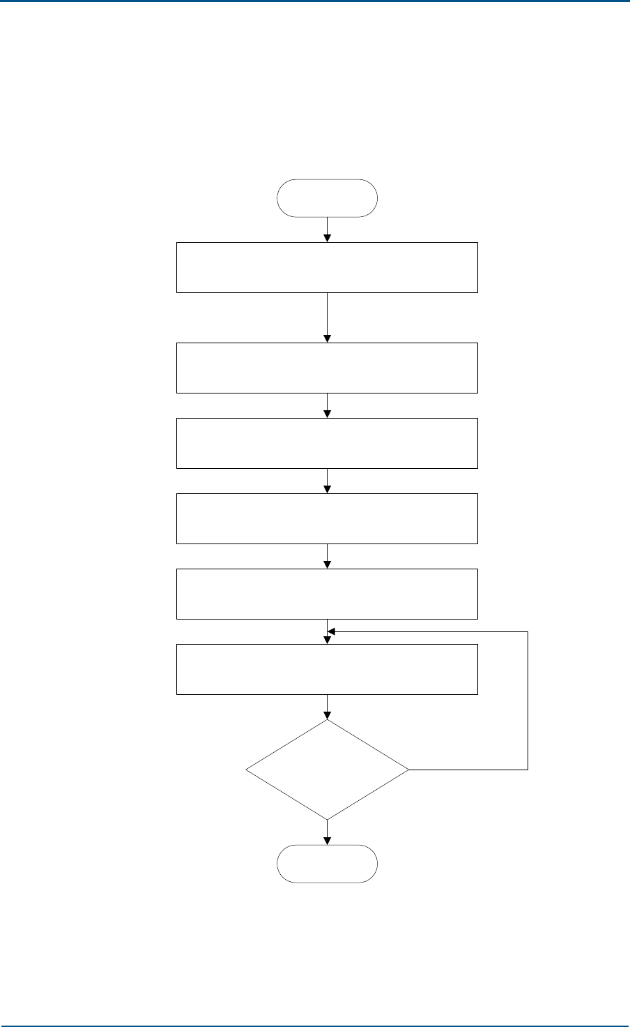
Ground Installation Mode Flow
Figure 6 illustrates ground installation mode flow chart.
FIGURE 6 - GROUND INSTALLATION MODE FLOW
Start
Building a concrete platform
Drawing lines
Drilling holes
Installing expansion bolt
Fixing channel steel
Fixing cabinet
Insulation test
End
No
Yes
ZXC10 CBTS O1 Hardware Installation Manual
34 Confidential and Proprietary Information of ZTE CORPORATION
Take following steps for CBTS O1 ground installation:
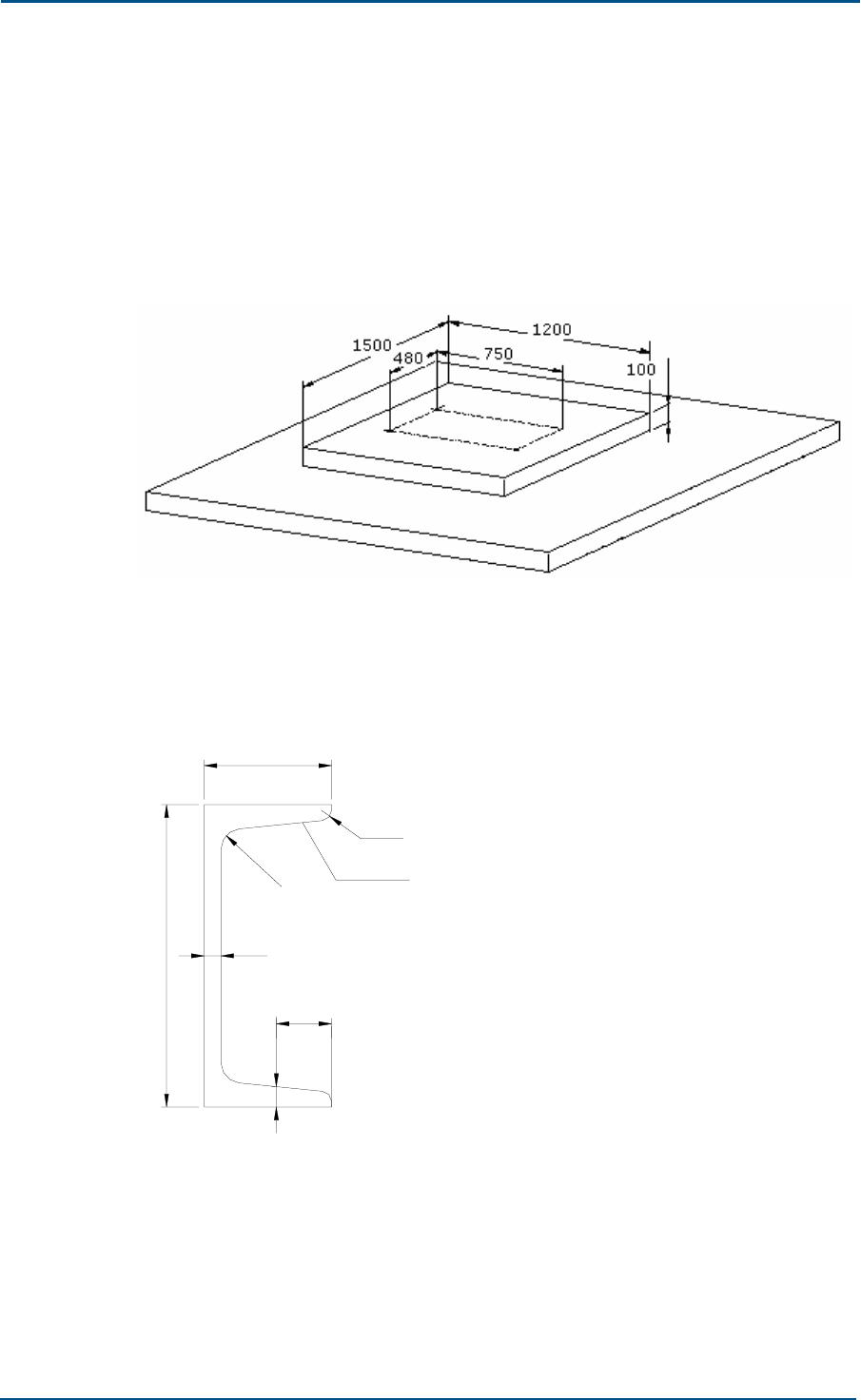
1. Building a concrete platform
Build a 47.24 inch x 59.05 inch x 3.39 inch (1200 mm × 1500 mm ×
100 mm) concrete platform. Figure 7 shows expansion bolt holes
dimensions 29.52 inch x 18.89 inch (750 mm × 480 mm) to install two
channel steel bars.
FIGURE 7 - SINGLE CABINET CONCRETE PLATFORM (UNITS MM)
Figure 8 shows 14b (GB/T707-1998) channel steel cross section.
FIGURE 8 - CHANNEL STEEL CROSS SECTION (UNITS MM)
Tilt 1:10
R9.5
60
9.5
26
R4.8
8
140
Chapter 3 - Cabinet Installation
Confidential and Proprietary Information of ZTE CORPORATION 35
2. Determine positions of four holes for installing channel steel according
to engineering design drawing. See Figure 9 for single.
FIGURE 9 - DRAWING LINES FOR SINGLE CABINET TOP VIEW (UNITS MM)
After drawing lines, measure lines once again to verify them.
3. Drilling holes
Drill φ14 holes, each 3.54 inch (90 mm) depth at marked positions for
ground expansion bolt holes. Keep drill bit vertical while drilling holes
with a percussion drill. Hold driller firmly and press downwards. Use
vacuum cleaner to clean dust while drilling.
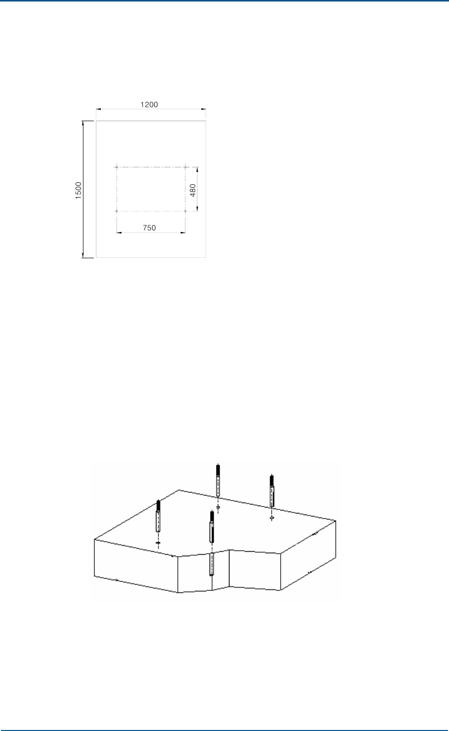
4. Expansion Bolt Installation
Put expansion bolt with tube in drilled hole and hammer it. Fix bolt
with nut using spanner and remove nut for cabinet installation. Torque
should not exceed 45 N-m. Figure 10 shows this process.
FIGURE 10 - EXPANSION BOLT INSTALLATION
ZXC10 CBTS O1 Hardware Installation Manual
36 Confidential and Proprietary Information of ZTE CORPORATION
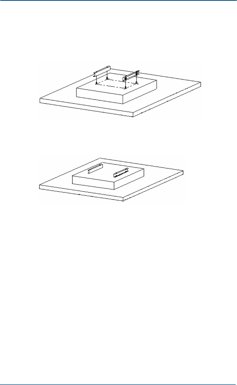
5. Fixing channel steel
Figure 11 shows to fix channel steel on concrete platform using
expansion bolts.
FIGURE 11 - FIXING CHANNEL STEEL
Figure 12 shows complete installation of channel steel.
FIGURE 12 - CHANNEL STEEL INSTALLATION
Chapter 3 - Cabinet Installation
Confidential and Proprietary Information of ZTE CORPORATION 37
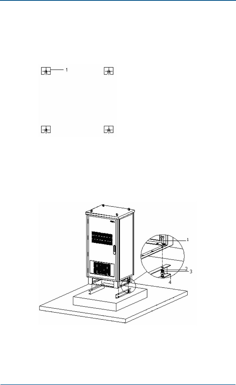
After channel steel installation, check its level with horizontal ruler.
Horizontal error should not more than 0.039 inch (1 mm). Figure 13
shows to minimize horizontal error according to ground level using
washers.
FIGURE 13 - MINIMIZING ERROR WITH WASHER
1. Adjusting Washer
6. Fixing cabinet
Move cabinet to installation position and fix it onto channel steel with 4
bolts. Figure 14 shows fixing cabinet.
FIGURE 14 - FIXING CABINET
1. Screw 2. Flat washer
3. Spring washer 4. Nut
ZXC10 CBTS O1 Hardware Installation Manual
38 Confidential and Proprietary Information of ZTE CORPORATION
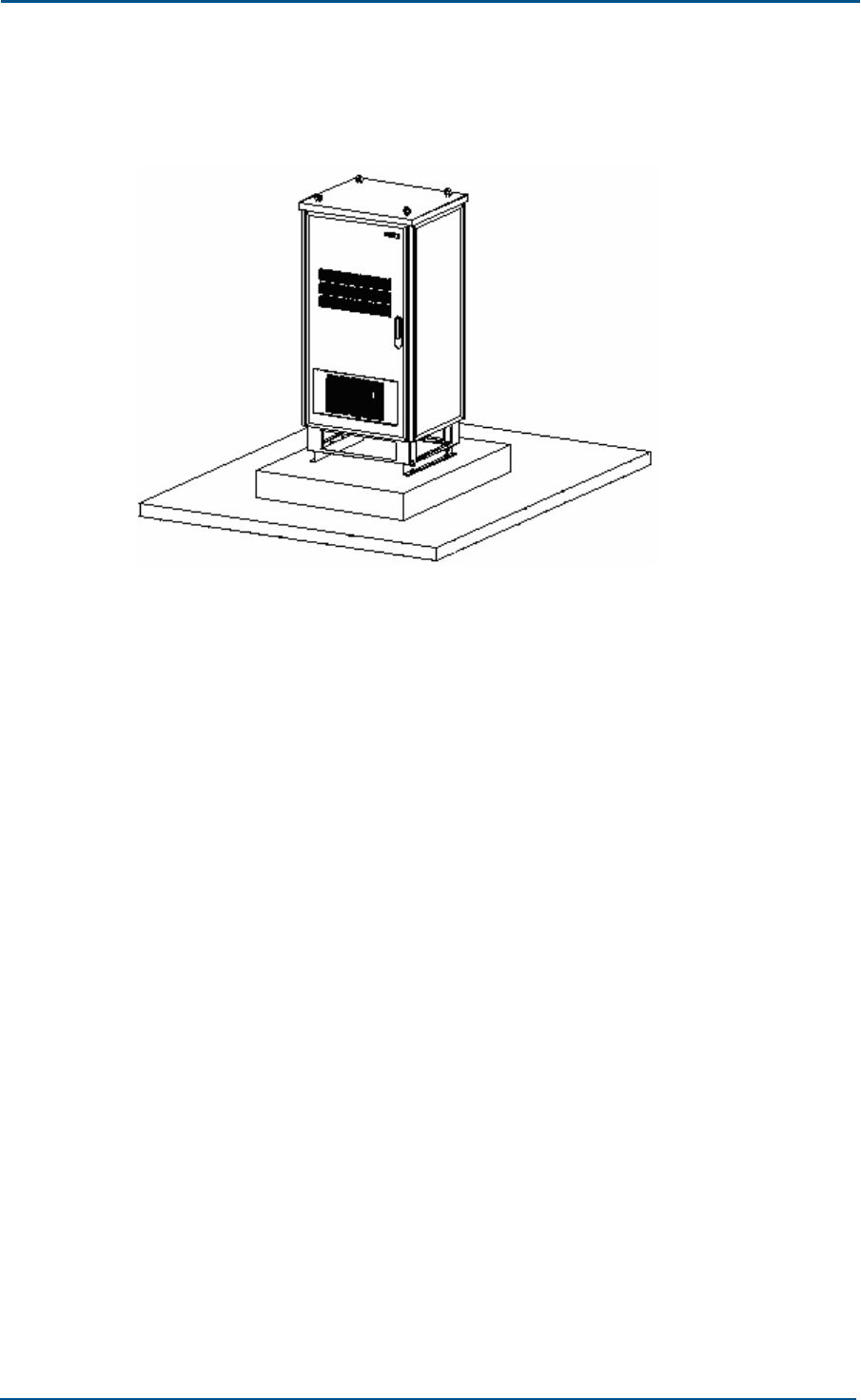
Figure 15 shows view of single cabinet after installation.
FIGURE 15 - SINGLE CABINET INSTALLATION
7. Insulation test
Use multimeter to measure resistance between expansion bolts and
cabinet. Open circuit indicates proper insulation. If result is otherwise,
check insulation again and repeat the test.
Chapter 3 - Cabinet Installation
Confidential and Proprietary Information of ZTE CORPORATION 39
Cabinet Accessories Installation
This section describes cabinet accessories installation. Following are
cabinet accessories:
Heat exchanger
Shutter
Power subrack
Windshield cover board
Heat Exchanger
Heat exchanger is already installed and is debugged before delivery.
Following section describes heat exchanger dismantling and installation
during maintenance.
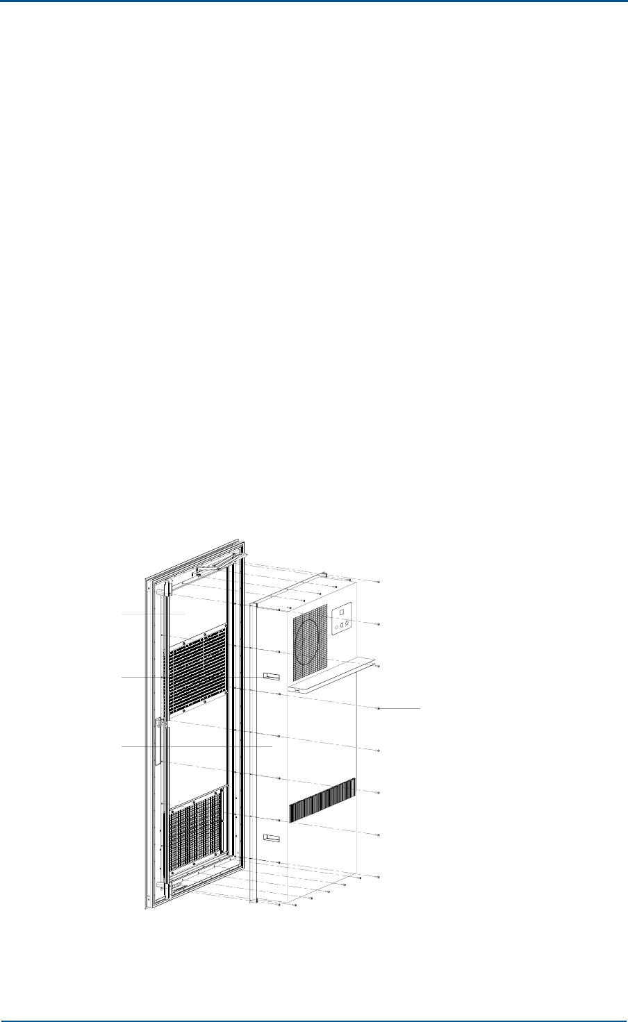
1. Dismante
After opening the front door, power off the heat exchanger and unplug
all the sockets. Remove twenty-six screws at the pressed edge, and
take out heat exchanger by holding the side handle. Figure 16 shows
this process.
FIGURE 16 - HEAT EXCHANGER DISMANTLING
4
3
2
1
1. Front door 2. Handle
3. Heat exchanger 4. Screw
ZXC10 CBTS O1 Hardware Installation Manual
40 Confidential and Proprietary Information of ZTE CORPORATION
2. Installation
Fix heat exchanger on front door with the removed twenty-six screws;
make sure to fasten the screws.
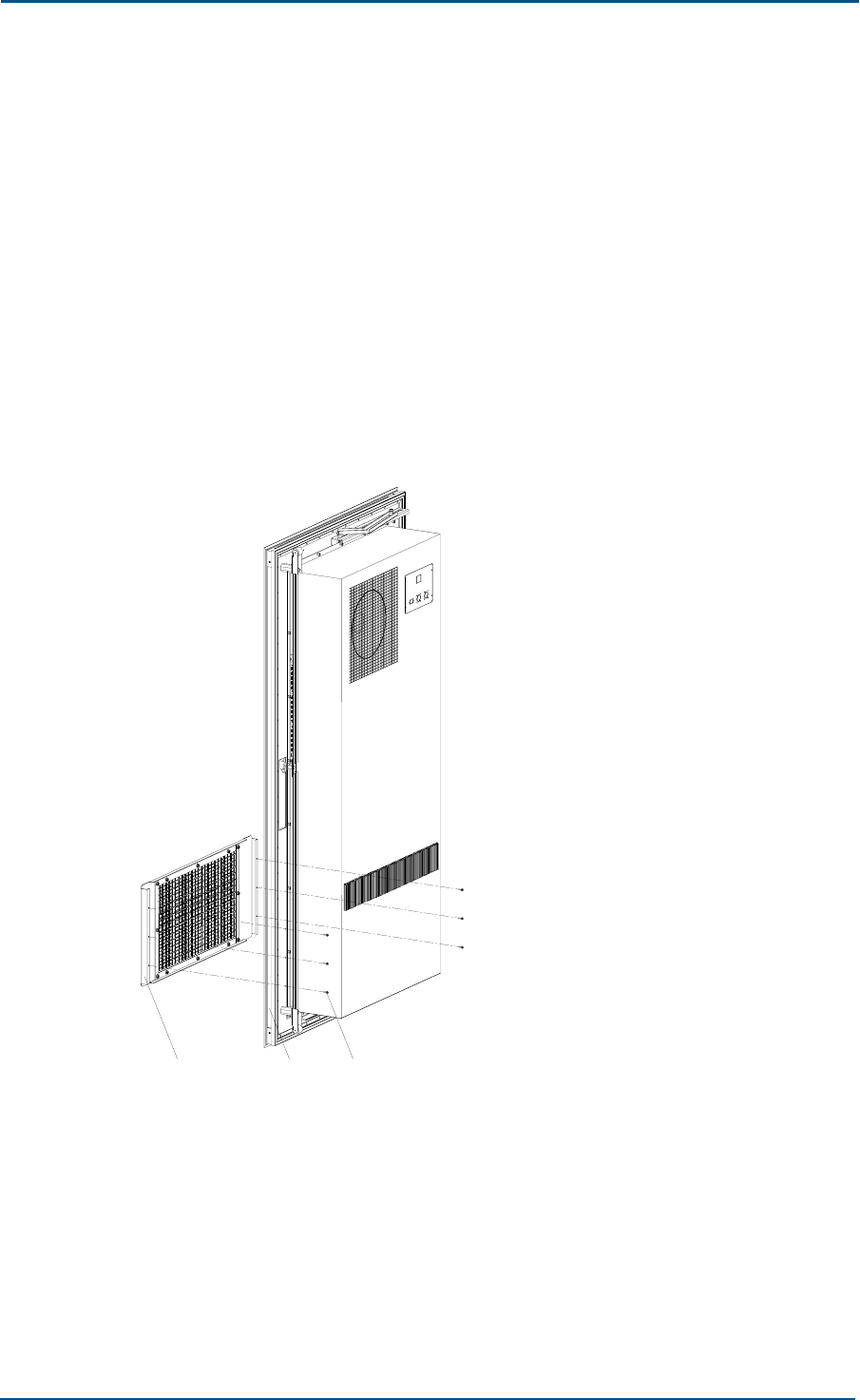
Shutter
Follow procedure below to remove and install shutter during maintenance.
1. Remove
After opening front door, remove the six screws inside the front door.
Figure 17 shows this process. Take out shutter directly through front
door. Heat exchanger is removal is optional.
FIGURE 17 - SHUTTER DISMANTLING
321
1. Shutter 2. Front door
3. Screw
2. Installation
Fix shutter on outside front door with the removed six screws and
make sure to fasten the screws.
Chapter 3 - Cabinet Installation
Confidential and Proprietary Information of ZTE CORPORATION 41
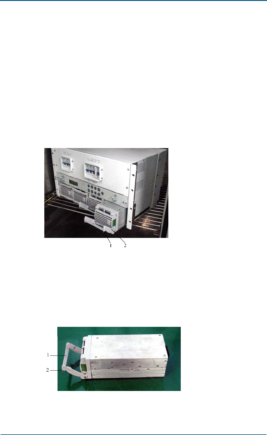
Power Subrack
Power subrack is already installed and is debugged before delivery.
Following section describes method for rectifier module installation in
subrack during maintenance.
Install power subrack with a maximum of four rectifier modules, in 3+1
backup mode and accept hot plugging.
1. Dismantle
i. Loosen both side screws on module handle and put handle into
OPEN state.
ii. Hold handle and take out module, Figure 18 shows this process.
FIGURE 18 - TAKING OUT RECTIFIER MODULE
1. Screw 2. Handle
2. Installation
Loosen both side screws on module handle and put handle into OPEN
state, Figure 19 shows this process.
FIGURE 19 - RECTIFIER MODULE – HANDLE IN OPEN STATE
1. Handle 2. Screw
ZXC10 CBTS O1 Hardware Installation Manual
42 Confidential and Proprietary Information of ZTE CORPORATION
i. Insert module into the cabinet along the guide rail.
ii. After module is inserted, press handle into right position (so that it
touches backplane properly), and fasten screws on both sides of
handle.
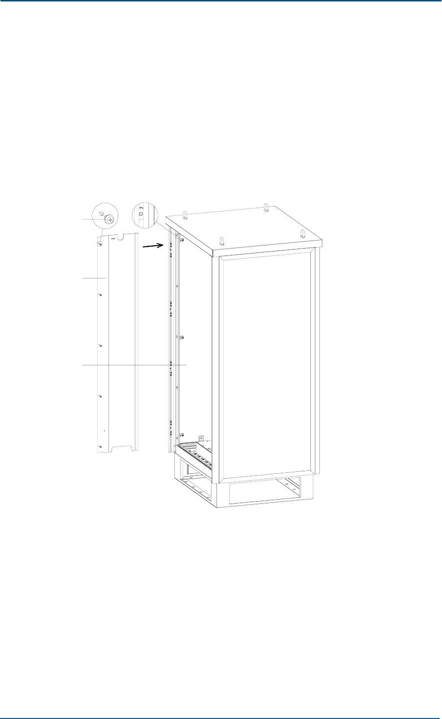
Windshield Cover Board
Install windshield cover board after internal cable installation. Put cover
board into cabinet according to arrow direction, and fix it onto right
position with 5 screws, Figure 20 shows this process.
FIGURE 20 - WINDSHIELD COVER BOARD INSTALLATION
3
2
1
1. Screw 2. Windshield cover board
3. Cabinet
Chapter 3 - Cabinet Installation
Confidential and Proprietary Information of ZTE CORPORATION 43
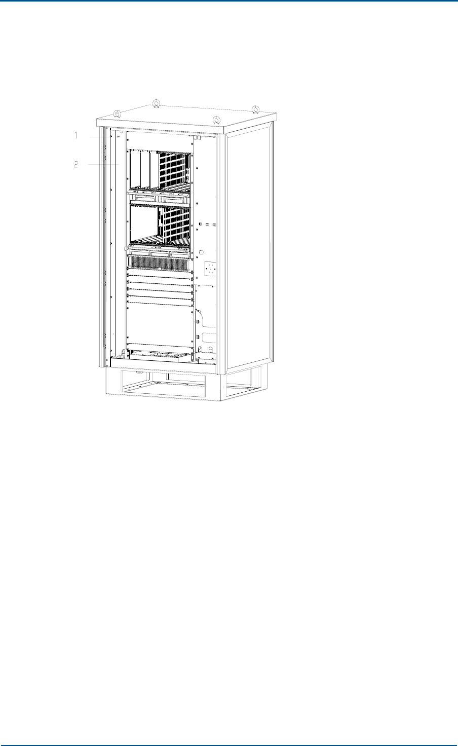
Figure 21 Completing Installation shows complete installation.
FIGURE 21 COMPLETING INSTALLATION
1. Screw 2. Windshield cover board

ZXC10 CBTS O1 Hardware Installation Manual
44 Confidential and Proprietary Information of ZTE CORPORATION
This page is intentionally blank.

Confidential and Proprietary Information of ZTE CORPORATION 45
Chapter 4
Cable Installation
This chapter describes cable installation:
Power and grounding cables
Power cable installation
External cable installation
Cable installation requirements

ZXC10 CBTS O1 Hardware Installation Manual
46 Confidential and Proprietary Information of ZTE CORPORATION
Power and Grounding Cables
ZXC10 CBTS O1 power and grounding cables are located at cabinet bottom.
Power cable
Power cables have cross section area of 16 mm2 and are fed with 220V
AC. Live wire is brown and neutral wire is black.
PE protection ground cable
Ground cable has cross section area of 35 mm² and is yellowish green.
Power Cable Installation
CBTS O1 internal cables are already installed in factory, install external AC
power and ground cables on site according to specific engineering design
drawing Connect main power cable from cabinet bottom to AC_IN interface
according to marked polarities. Refer to Cabinet External Cable Installation
section for details. Table 11 describes power cable interface signals.
TABLE 11 - AC 220 V INTERFACE
Pin Signal
Definition Signal Description End-A Entity End-B
Entity
1 L AC live wire L, with maximum
current of 60A
AC power distribution
device ACCU unit
2 N AC neutral wire N, with
maximum current of 60A
3 PE AC protection ground PE
Caution:
Ensure that power and grounding cables are according to engineering
specifications and standards.
Take all measures to guarantee staff and equipment safety.
Chapter 4 - Cable Installation
Confidential and Proprietary Information of ZTE CORPORATION 47
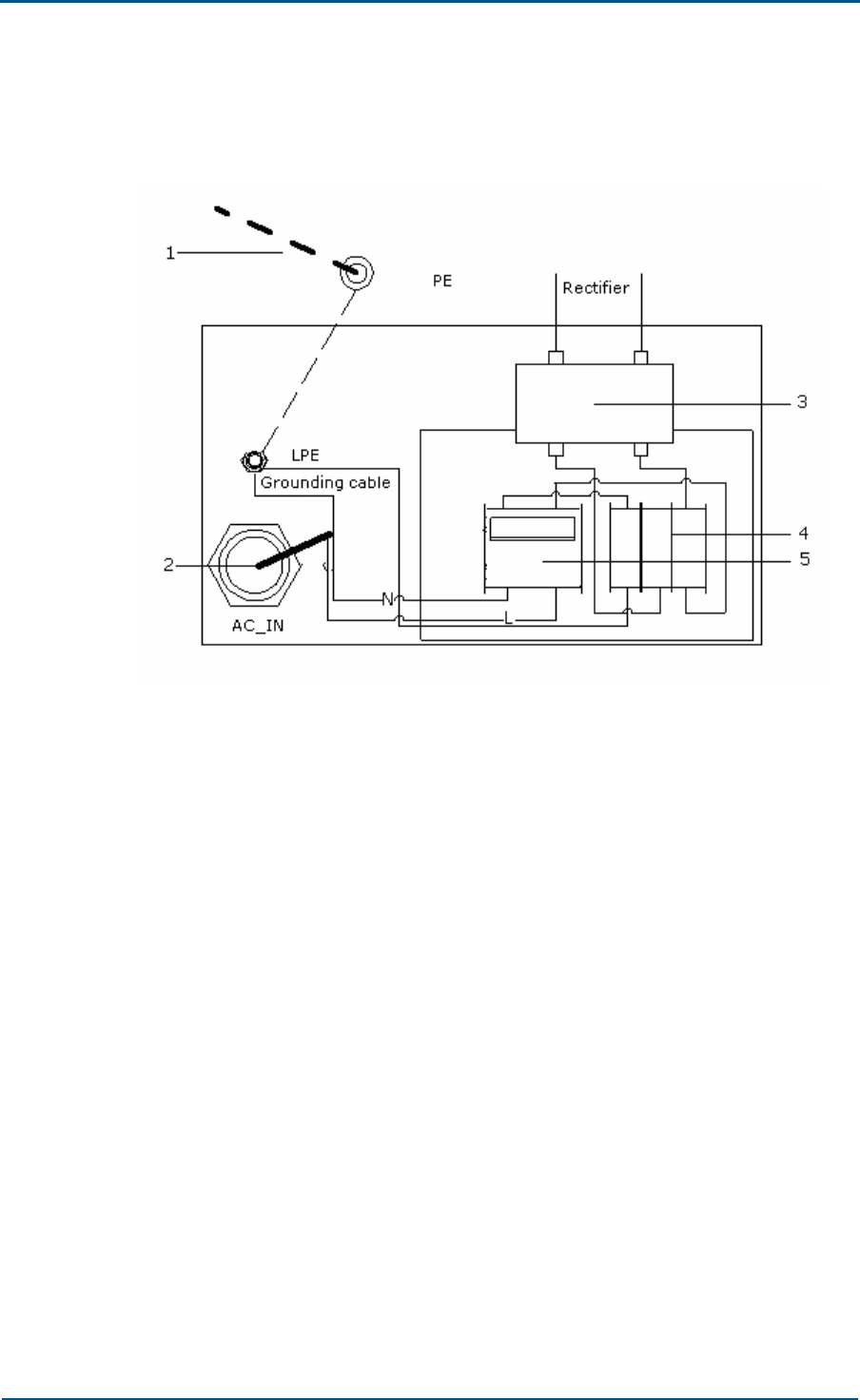
Connect power and grounding cables according to engineering design
drawing. Figure 22 shows power and grounding cable connections.
FIGURE 22 - POWER AND GROUNDING CABLE CONNECTIONS
1. Grounding cable 2. AC power cable
3. AC power filter 4. Lightning arrester
5. AC switch
ZXC10 CBTS O1 Hardware Installation Manual
48 Confidential and Proprietary Information of ZTE CORPORATION
External Cable Installation
Connect all external cables through interface at cabinet bottom. Following
are external cable types:
AC_IN power cable
Battery power cable
E1/T1 cable
Optical cable and microwave intermediate frequency cable
PE ground cable
RF cable
GPS Antenna feeder RF cable
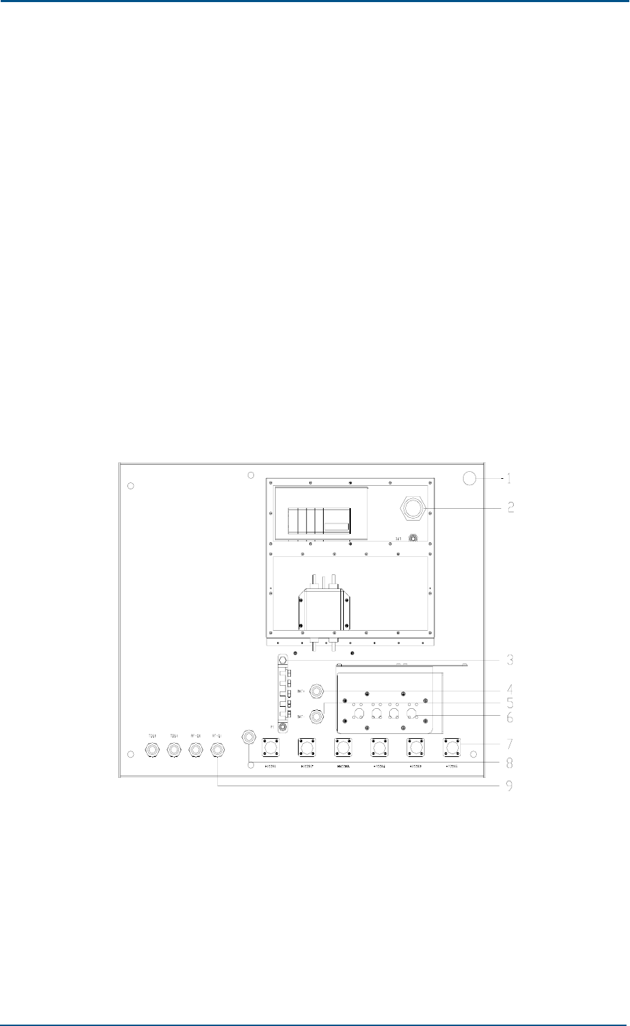
Figure 23 shows CBTS O1 cabinet bottom interface top view. Ensure that
all external connections are waterproof and corrosion resistive.
FIGURE 23 - CABINET BOTTOM INTERFACE TOP VIEW
1. GPS antenna 2. AC power cable
3. PE protection ground 4. Battery positive terminal
5. Battery negative terminal 6. E1/ T1
7. Main feeder cable 8. Ventilation hole
9. Optical fiber
Chapter 4 - Cable Installation
Confidential and Proprietary Information of ZTE CORPORATION 49
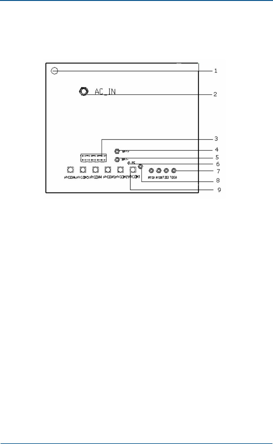
Figure 24 shows cabinet bottom interfaces bottom view
FIGURE 24 - CABINET BOTTOM INTERFACE BOTTOM VIEW
1. GPS antenna 2. AC power cable
3. Protection ground 4. Battery positive terminal
5. Battery negative terminal 6. E1/ T1
7. Main feeder cable 8. Ventilation hole
9. Optical fiber
For GPS cable installation refer to corresponding chapter.

ZXC10 CBTS O1 Hardware Installation Manual
50 Confidential and Proprietary Information of ZTE CORPORATION
Table 12 shows cable connection relationship
TABLE 12 - CABLE CONNECTION RELATIONSHIP
S.N. Interface
Name
Socket
Type
External cable
name Quantity End A End B
1 HYCOM1 ~
HYCOM 6
7/16-hole
socket
Antenna feeder
RF cable 6 RFE Antenna
2 AC_IN Hummel
connector
AC_IN power
cable 1 ACCU unit
AC power
distribution
device
3 PE Ground pole
PE cabinet
protection
ground cable
1
Cabinet PE
connecting
terminal
Protection
grounding
busbar
4 Fiber 1 ~
4
Cable
traverser
Optical cable and
microwave trunk 2 Transmissi
on Unit
Remote
transmission
5 BAT+ Hummel
connector
+ Battery rack
power cable 1 Battery rack
6 BAT- Hummel
connector
- Battery rack
power cable 1
DCCU unit
Battery rack
7 GPS N-F
connector GPS cable 1 GCM board GPS antenna
8 ABIS Cable
traverser
Abis interface E1/
T1 cable 2 Master
cabinet
External
transmission
device or BSC
Antenna Feeder RF Cable
Um interface implements radio signal transmission by employing antenna.
There are 6 antenna feeder interfaces at CBTS O1 cabinet bottom:
HYCOM1 ~ HYCOM6. Connect cabinet external interface to antenna feeder
jumper and internal interface to ANT port of corresponding RFE board.
Antenna feeder interfaces transmits RF carrier signals between BTS and
MS. Use 7/16 female socket connector. Table 13 illustrates antenna feeder
interfaces.
TABLE 13 - ANTENNA FEEDER INTERFACES
Pin Signal
Definition Signal Description End-A Entity End-B Entity
HYCOM TX-RF
Internal
conductor HYCOM RX-RF
Shielding layer GND -
RFE Antenna
Chapter 4 - Cable Installation
Confidential and Proprietary Information of ZTE CORPORATION 51
Battery Cables
CBTS O1 cabinet has small battery setup due to volume restrictions. Use
external battery for uninterrupted power supply in case of main AC failure
for longer time. There are two battery terminals marked as BAT+ and
BAT- on cabinet for external connection.
Optical Cable & Microwave Intermediate
Frequency Cable
There are four entrance points for optical fiber cable at cabinet bottom
marked as FIBER 1, FIBER 2, FIBER 3 and FIBER 4.
Fiber splice tray provides 2 pairs of FC/PC interfaces (flange) and meets
requirements for fiber fusion and coiling. Use it to connect fiber end inside
the cabinet and optical cable outside the cabinet. Fiber splice tray is
installed on cabinet backplane left side. Figure 25 shows fiber splice tray
FIGURE 25 - FIBER SPLICE TRAY
1
1. Flange installation jack
Route the external optical cables into cabinet from cabling hole at cabinet
bottom. Splice internal fiber cable and FC connector with fiber splicer to
connect fiber to flange. Route the fiber tail from cabinet to corresponding
ZXSM T150 optical interface for connections.
ZXC10 CBTS O1 Hardware Installation Manual
52 Confidential and Proprietary Information of ZTE CORPORATION
E1/T1 Cable
Abis interface adopts E1/T1 interface.
E1/T1 cable connects external transmission device or BSC through Abis
interface. There are two types of E1 cables, 75 ohm and 120 ohm
impedance cables.
Figure 26 shows 75 ohm E1 cable interface with eight ports. Route all
external E1 cables through these ports.
FIGURE 26 - E1 CABLE INTERFACE
T4
R4 T3 R3 T2 R2
T1 R1
R8 T8
R7T7 R6 T6
R5 T5
Figure 27shows 120 ohm E1 and 100 ohm T1 interface. CBTS O1 cabinet
transmits signals via DB44 connectors. All internal cables are assembled in
factory, only install external cables through specific route. Connect E1/T1
cables to aviation plugs on converter bottom. Figure 27 - 120 OHM E1 and
100 OHM T1 Interface shows interfaces.

Chapter 4 - Cable Installation
Confidential and Proprietary Information of ZTE CORPORATION 53
FIGURE 27 - 120 OHM E1 AND 100 OHM T1 INTERFACE
ZXC10 CBTS O1 Hardware Installation Manual
54 Confidential and Proprietary Information of ZTE CORPORATION
Cable Installation Requirements
Ensure following requirements during cable installation:
Install power supply and grounding cables separately.
Ensure that distance between cable bundles is at least 7.87 inch (200
mm).
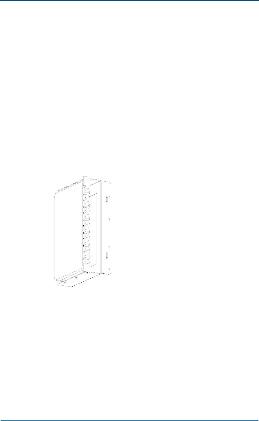
Cut cable ties flat after making cable bundles.
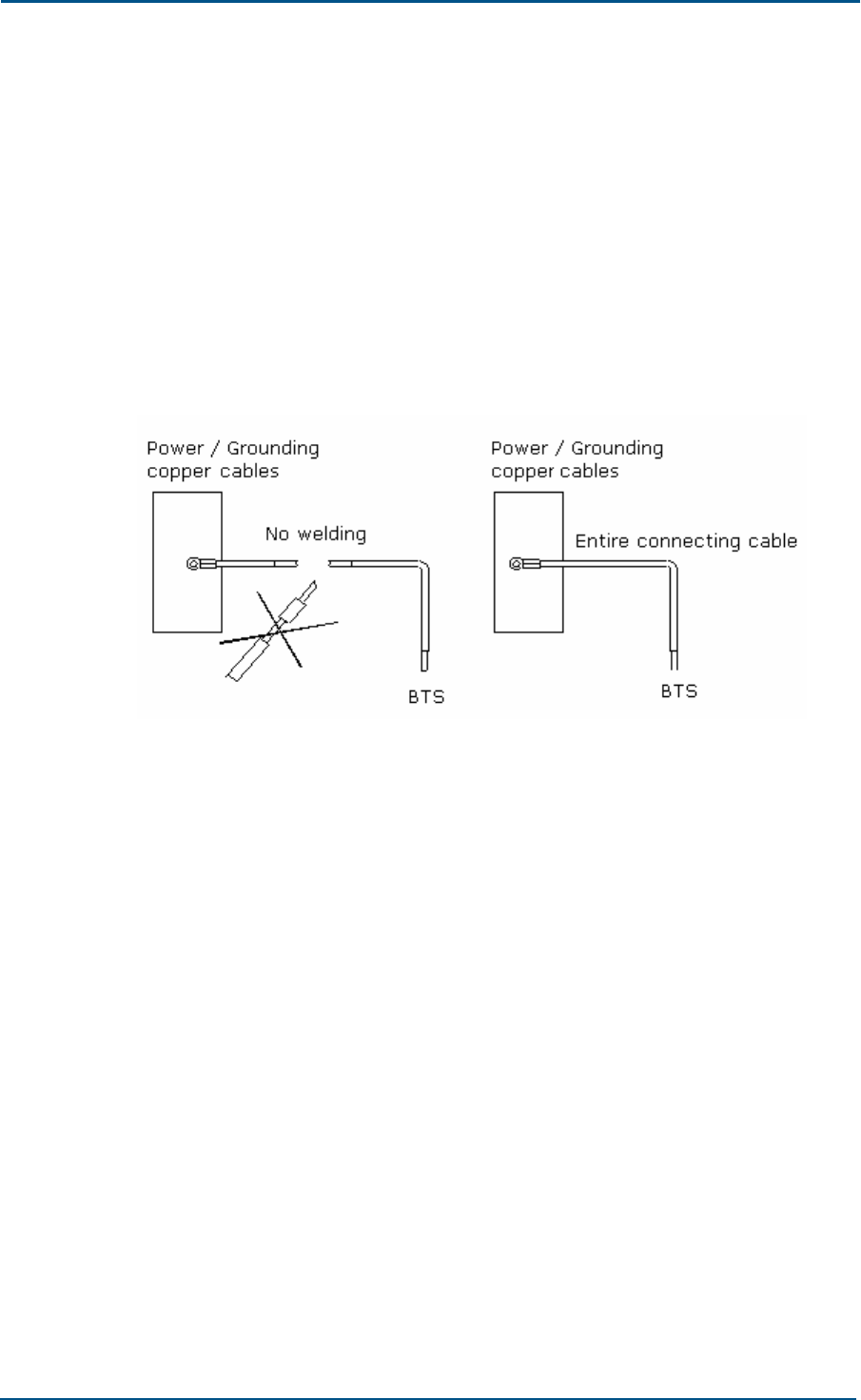
Measure cable lengths before installation. Avoid cable connections or
welding. Figure 28 illustrates this process.
FIGURE 28 - POWER SUPPLY AND GROUNDING CABLES
Ensure less contact resistance between cable and busbar by using plain
and spring washers while fixing the lugs.
Separately install E1 / T1 cables for each single cabinet.
Cable type, quantity, routing, length and installation position must be
according to engineering design drawings.
Before cable installation, ensure that are not damaged and all cables
have delivery logs and quality certificate to ensure product quality.
Use cable tie or wax cable bundle during cable installation. Keep cable
tie maximum length between two cables up to 39.37 inch (1 m).
Ensure cable ties are not too tight.
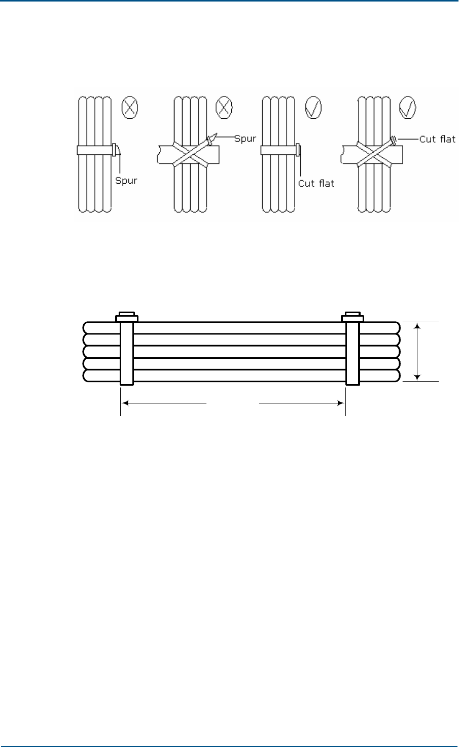
Use different cable strap according to circumstance, avoid using two or
more cable straps for bundling. Cut cable straps flat after bundling.
Chapter 4 - Cable Installation
Confidential and Proprietary Information of ZTE CORPORATION 55
Figure 29 shows difference between correct and incorrect bundle.
FIGURE 29 - CABLE STRAPS REQUIREMENTS
Keep space between each two cable straps up to 3~4 times longer
than bundle diameter. Figure 30 shows this process.
FIGURE 30 - CABLE STRAPS
d
3d ~4d

Confidential and Proprietary Information of ZTE CORPORATION 56
Chapter 5
Main Antenna Feeder System
Installation
This chapter describes main antenna feeder system installation:
Main antenna feeder system installation
Antenna installation preparation
Antenna installation precautions
Main antenna feeder system structure
Antenna types
Super flexible jumper
Main feeder cable
Grounding kit
Lightning arrester
Antenna feeder system connectors
Antenna installation technical parameters
Antenna installation flow chart
Selecting installation position
Moving and hoisting antenna
Uni-directional antenna installation
Omni-directional antenna installation
Main feeder installation
Antenna jumper installation
Feeder cable installation
Lightning arrester installation
Grounding kit installation
Cabinet jumper installation
Testing antenna feeder system
Waterproofing connectors

Chapter 5 - Main Antenna Feeder System Installation
Confidential and Proprietary Information of ZTE CORPORATION 57
Main Antenna Feeder System
Installation
Antenna Installation Preparation
Proper antenna installation ensures BSS system reliable operation. Install
antenna according to specific network planning engineering design. Install
antenna in correct direction, elevation, gain and diversity reception modes
including correct tilt and azimuth for each sector. Ensure antennas wind
resistance capability maximum up to 150 km/h.
Before antenna system installation, ensure that installation personnel
working at tower height are qualified. Inspect installation tools and feeder
equipment.
Antenna Installation Precautions
Take necessary measures for personal and equipment safety.
Operator on tower must wear safety belt.
Personnel under tower must wear safety helmets.
Never climb tower with loose clothes and wet/slippery shoes.
While active antenna adjustment, wear radiation-shielding clothing and
turn off high power amplifier to avoid radiation effects.
Main Antenna Feeder System Structure
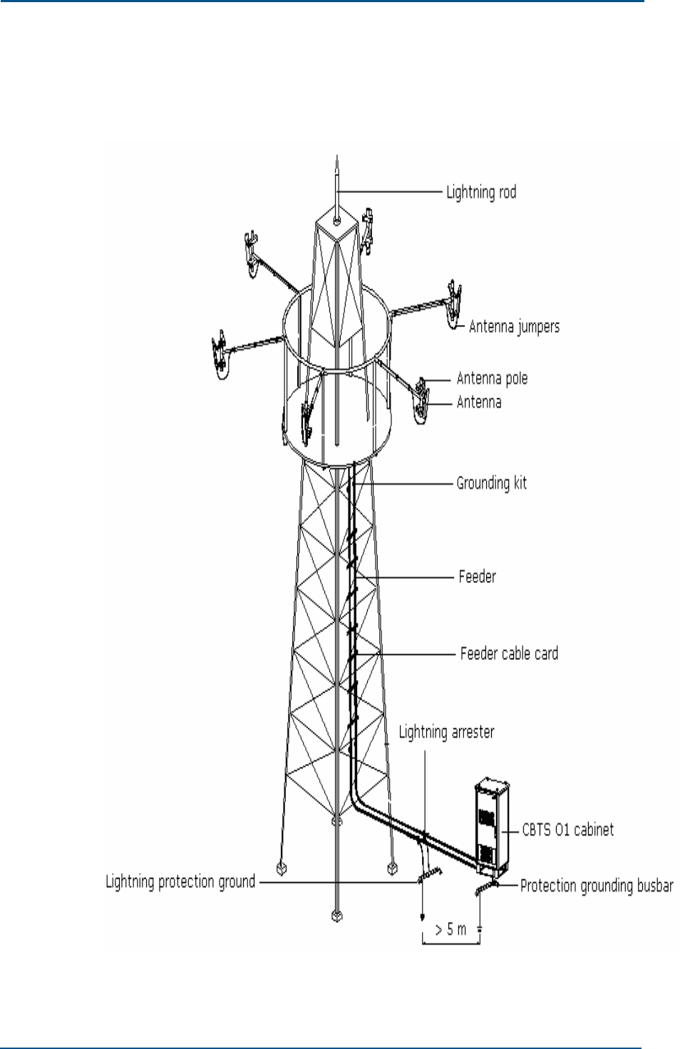
The main antenna feeder system consists of:
Lightening rod
Antenna jumpers
Antenna pole
Antennas
Grounding kit
Feeder
Feeder cable card
Grounding kit
Lightning rod
Lightning protection ground
CBTS O1 cabinet
Protection grounding busbar
ZXC10 CBTS O1 Hardware Installation Manual
58 Confidential and Proprietary Information of ZTE CORPORATION
Figure 31 shows 3-sector antenna feeder system structure.
FIGURE 31 - 3-SECTOR ANTENNA FEEDER SYSTEM
Chapter 5 - Main Antenna Feeder System Installation
Confidential and Proprietary Information of ZTE CORPORATION 59
Antennas Types
There are two main CBTS O1 antenna types:
Uni-directional
Omni-directional
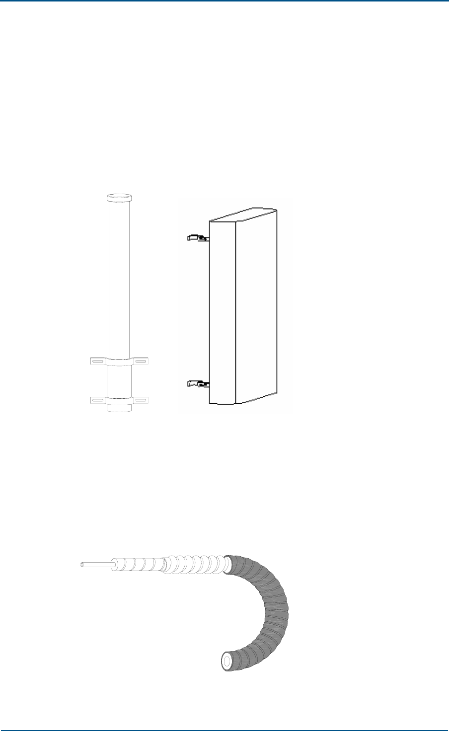
Figure 32 shows directional antenna on right side and omni-directional
antenna on left side.
FIGURE 32 - OMNI AND UNI-DIRECTIONAL ANTENNAS
Super Flexible Jumper
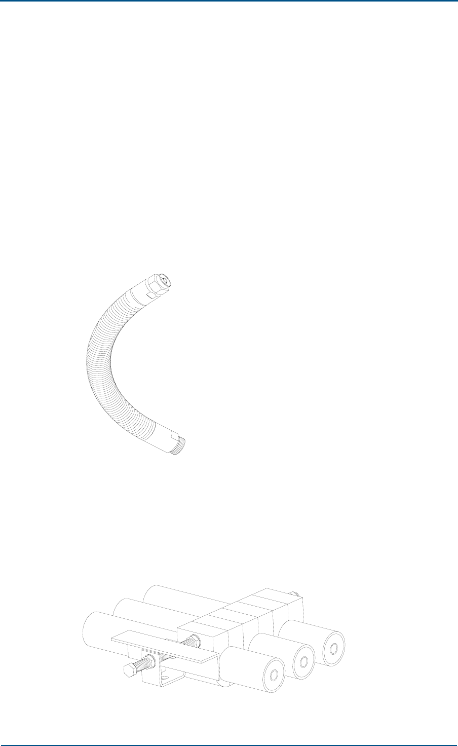
Use super-flexible jumper where a small bending radius is required.
Threads on its surface make it highly flexible and able to resist pressure.
Use 1/2" super-flexible jumpers to connect antenna to main feeder cable
and main feeder to cabinet. Figure 33 shows super flexible cable.
FIGURE 33 - SUPER FLEXIBLE JUMPER
ZXC10 CBTS O1 Hardware Installation Manual
60 Confidential and Proprietary Information of ZTE CORPORATION
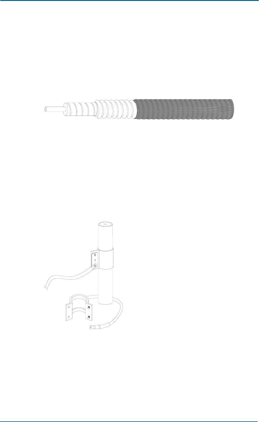
Main Feeder Cable
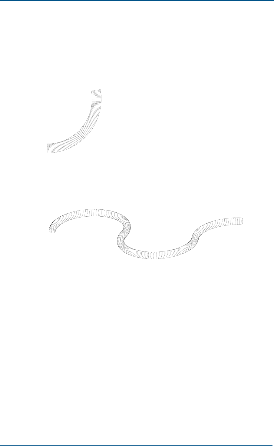
Use 7/8" feeder cable between antenna jumper and cabinet top jumper.
Figure 34 shows main feeder cable, common foam insulating feeder cable
consists of internal and external conductors. Internal conductor is wrapped
with low-loss foam insulator. Feeder cable is covered with a fire and
smoke proof sheath.
FIGURE 34 - MAIN FEEDER CABLE
Grounding Kit
Use grounding kit to protect antenna feeder cables and other devices
against lightning. Mount grounding kit according to conditions such as: on
tower top, tower bottom and at transceiver entrance for grounding. Figure
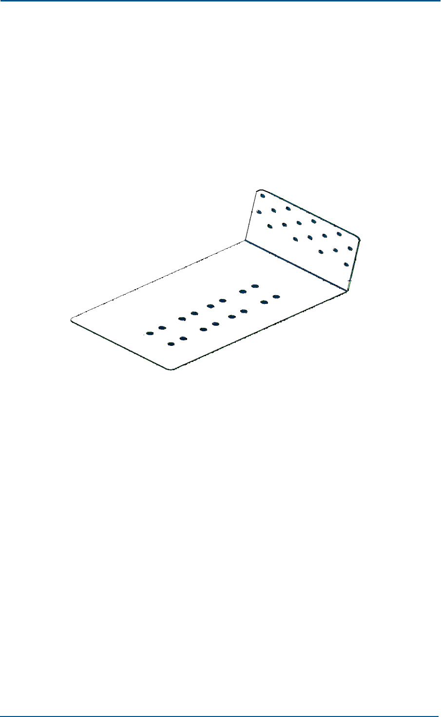
35 shows grounding kit.
FIGURE 35 - GROUNDING KIT
Chapter 5 - Main Antenna Feeder System Installation
Confidential and Proprietary Information of ZTE CORPORATION 61
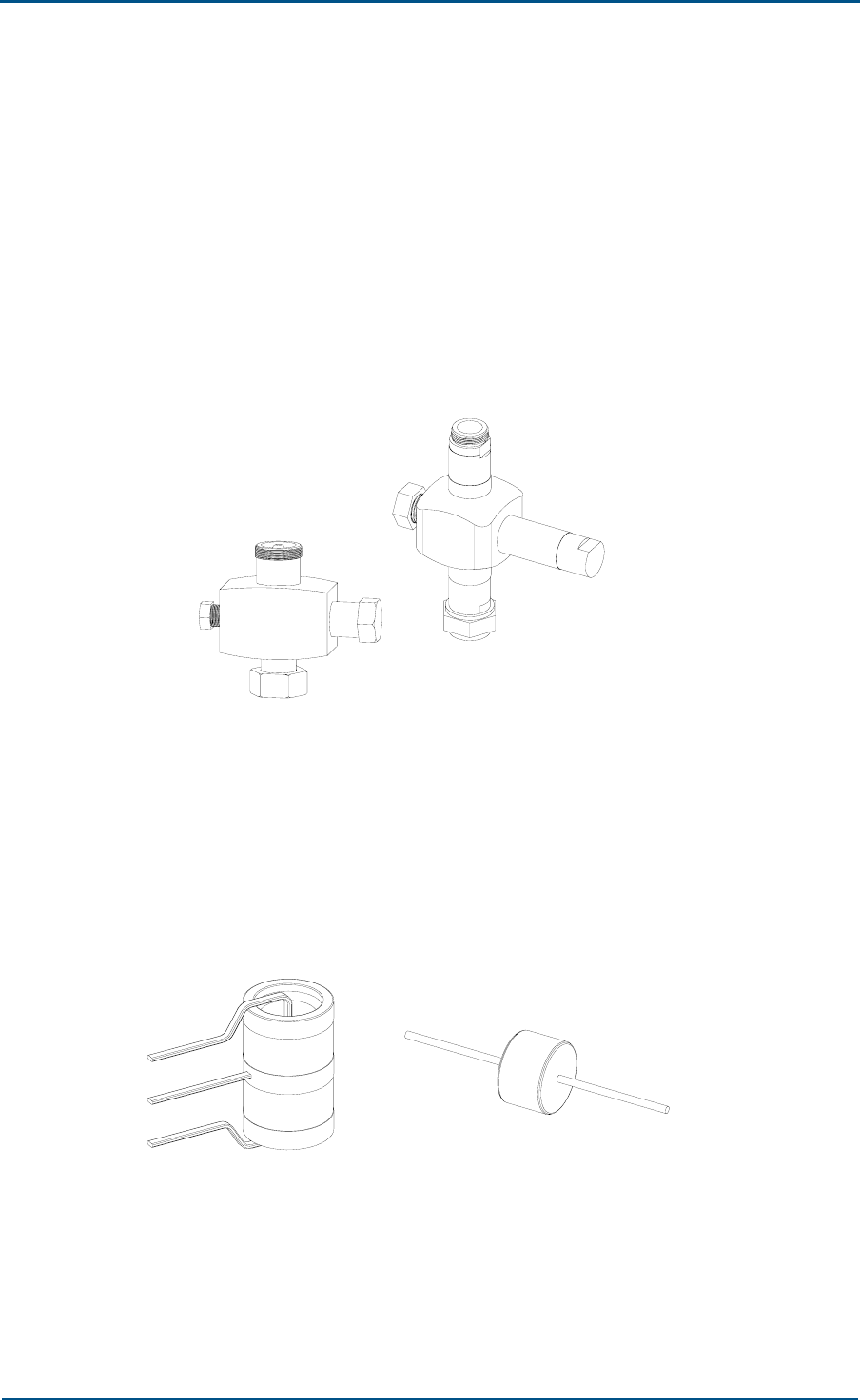
Lightning Arrester
Use lightning arrester to protect cable against lightning.
There are two types of common lightning arresters:
λ/4 stub lightning arrester
Figure 36 shows λ/4 stubs, it is a tri-port passive coaxial component.
Length of each third port is one quarter of wavelength and its external
and internal conductors are short-circuited. Its working principle is
similar to that of band pass filter.
FIGURE 36 - λ/4 STUB LIGHTNING ARRESTER
Graviton lightning arrester
Graviton is a short-circuited protection part encapsulated in ceramics
or glass and filled with low-pressure inert gas. Figure 37 shows two
types of graviton lightning arresters: three electrode on left and dual
electrode graviton on right side.
FIGURE 37 - GRAVITON LIGHTNING ARRESTERS
The basic working principle of the graviton is gas discharge. Do not
use graviton in case of excessive currents more 10 kA. Usually, a
graviton has a life of 5 years.
ZXC10 CBTS O1 Hardware Installation Manual
62 Confidential and Proprietary Information of ZTE CORPORATION
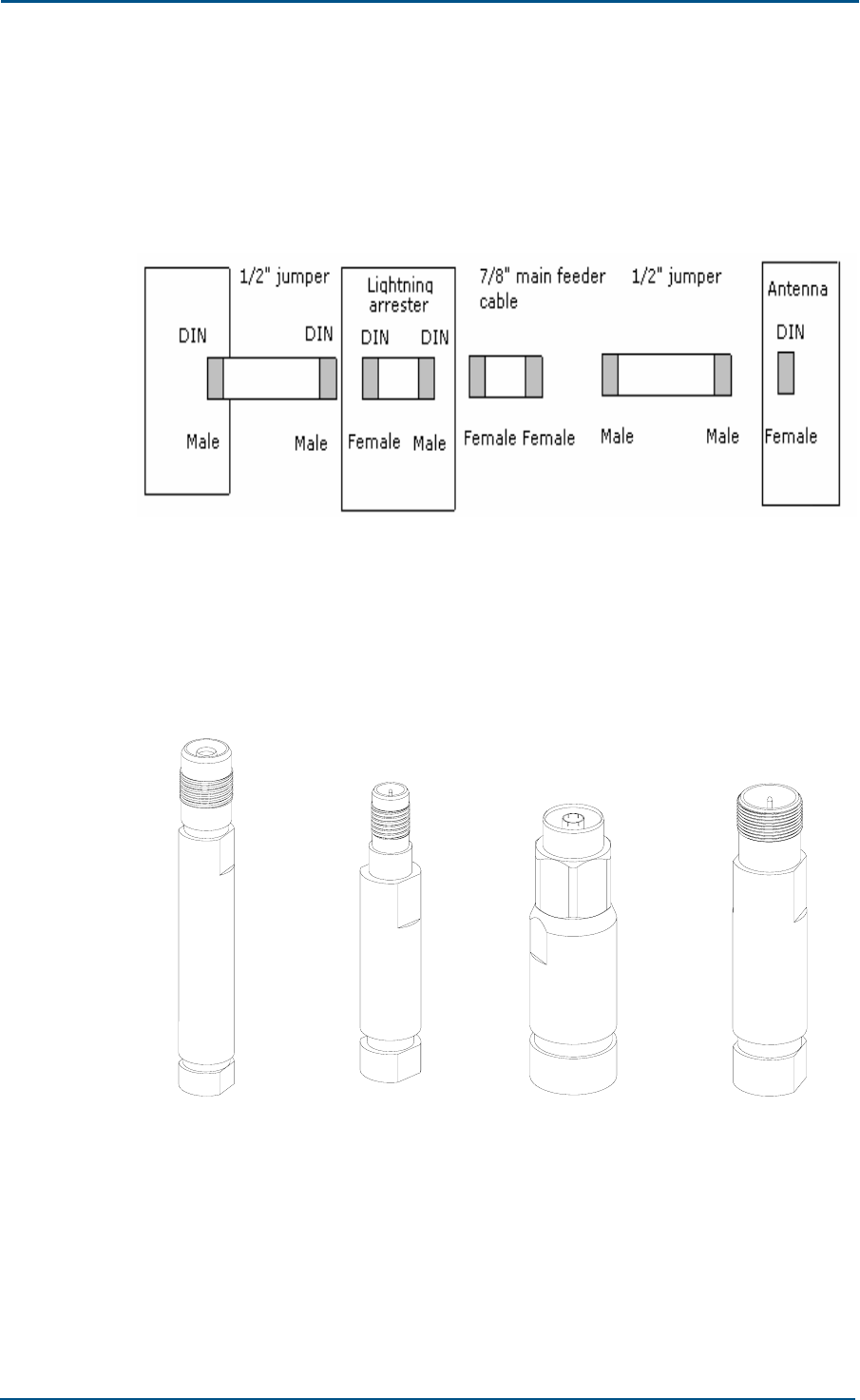
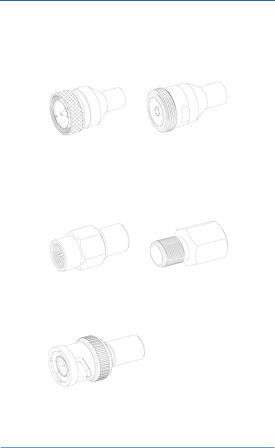
Antenna Feeder System Connectors
Figure 38 shows all connectors in antenna feeder system. Following
sections describes antenna feeder system connectors.
FIGURE 38 - CONNECTORS IN ANTENNA FEEDER SYSTEM
DIN series connectors are medium and large power connectors with
threads. Use DIN series connectors to connect RF coaxial cables in
vibration and adverse environments. Figure 39 shows 1/2" connector
on left and 7/8" connector on right side.
FIGURE 39 - DIN CONNECTORS
Chapter 5 - Main Antenna Feeder System Installation
Confidential and Proprietary Information of ZTE CORPORATION 63
Figure 40 shows 7/16 type series big threaded water proof coaxial
connectors, male connector on left and female connector on right side.
Use 7/16 type connectors as outdoor connectors for transmitting
medium and high energy.
FIGURE 40 - 7/16 CONNECTORS
Figure 41 shows SMA series threaded connectors with a characteristic
impedance of 50 Ω. Male connector is on left and female connector on
right side. External conductor inner diameter is 162.59 inch (4130
mm). Use SMA series RF coaxial connectors with semi-rigid and flexible
RF cables to situations requiring high performance microwave.
FIGURE 41 - SMA CONNECTORS
Figure 42 shows BNC connectors, which are bayonet socket RF coaxial
cable connectors manufactured according to MIL-C-39012 and IEC
169-8 specifications. Use BNC connectors as trunk connectors.
FIGURE 42 - BNC CONNECTOR (M)

ZXC10 CBTS O1 Hardware Installation Manual
64 Confidential and Proprietary Information of ZTE CORPORATION
Antenna Installation Technical Parameters
Height
It depends upon network planning.
Azimuth
It depends upon network planning.
Tilt
It depends upon network planning and ranges from 0° ~ 10°.
Antenna direction
It depends upon antenna azimuth. Two antennas in same sector should
point to same direction.
Spacing between diversity antennas
Two antennas in same sector act as diversity receiving antennas for
each other, and have same vertical height. Maximum horizontal
distance (d) between antennas satisfies engineering requirements.
Following formula determines value of horizontal distance (d):
d ≥ 10λ–20λ (or H/d = 11). Unit of measurement: m
Where:
d is horizontal distance between diversity antennas.
H is vertical height from antenna to ground.
λ is carrier wavelength.
For example, diversity distance of 1900 MHz carrier must be more than
59.055 inch (1.5 m) while that of 800 MHz carrier must be more than
137.79 inch (3.5 m).
Chapter 5 - Main Antenna Feeder System Installation
Confidential and Proprietary Information of ZTE CORPORATION 65
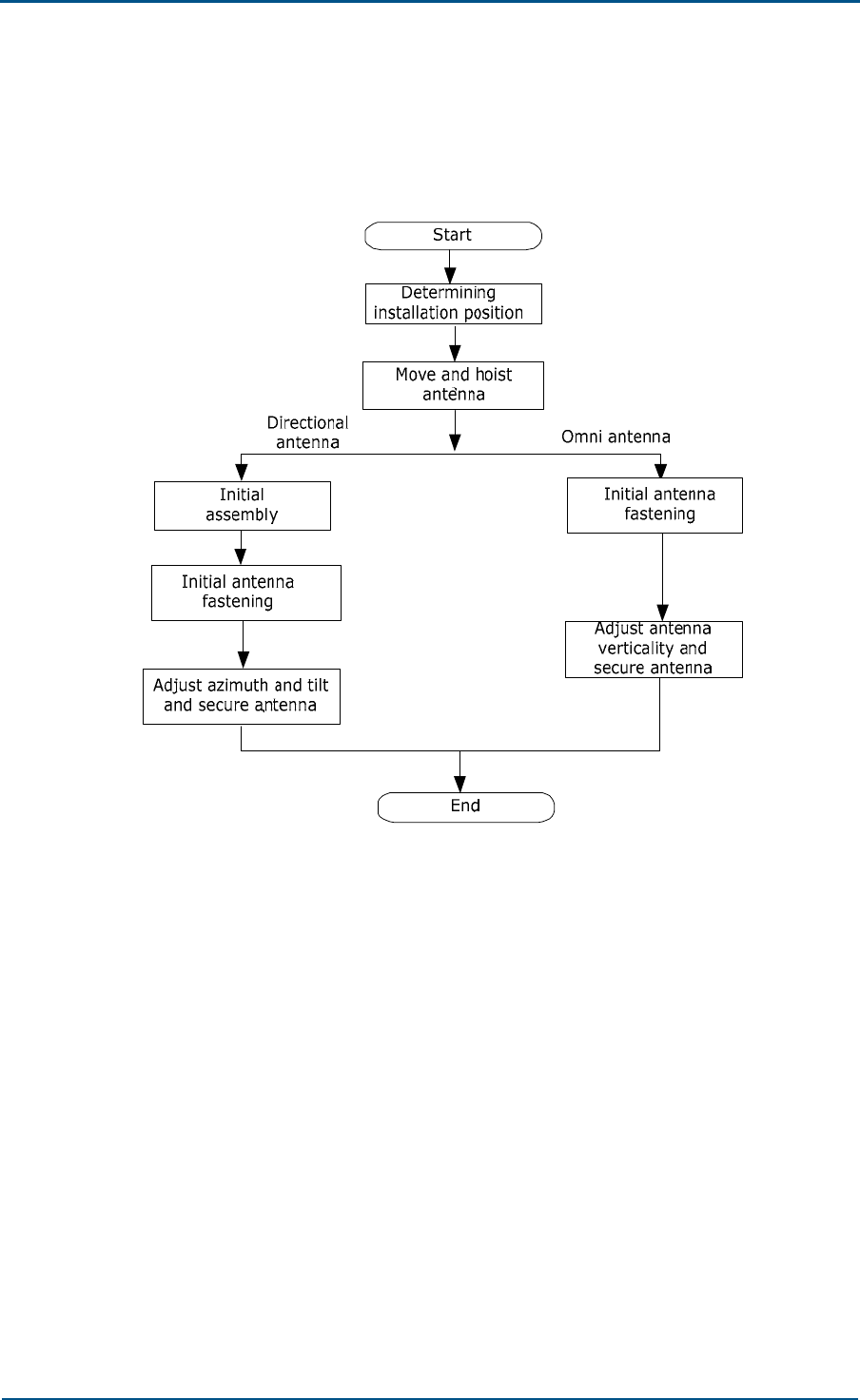
Antenna Installation Flow Chart
Figure 43 shows antenna installation flow chart.
FIGURE 43 - ANTENNA INSTALLATION FLOW CHART
Selecting Installation Position
Select installation position according to engineering design. Incase of
failure prepare a secondary engineering design, negotiating with customer
and design institute, based on: local coverage requirements, spatial
diversity requirements, antenna azimuth and tilt.
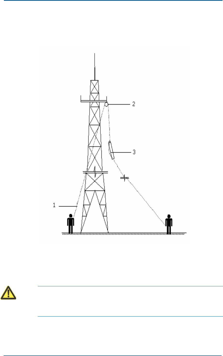
Moving and Hoisting Antenna
To mount an antenna on a tower, use rope and pulley block to hoist
antenna. Carry antenna jumper and all accessories such as measuring
tools, safety belts, adhesive tapes and straps to tower top platform and
keep them in a safe place.
Put small metal articles like antenna fixing parts and wrenches in a sealed
canvas tool bag before hoisting. Knot rope at both ends of antenna for
easy coordination of staff both on and under the tower.
ZXC10 CBTS O1 Hardware Installation Manual
66 Confidential and Proprietary Information of ZTE CORPORATION
Figure 44 illustrates hoisting process.
FIGURE 44 - HOISTING AN ANTENNA
1. Rope 2. Pulley block
3. Knot rope at both ends of antenna
To mount an antenna on roof, move antenna and installation materials to
installation position manually.
Caution:
Personnel on and under the tower should coordinate in hoisting an antenna.
Personnel under the tower should pull antenna away from tower body to avoid
damage.
Chapter 5 - Main Antenna Feeder System Installation
Confidential and Proprietary Information of ZTE CORPORATION 67
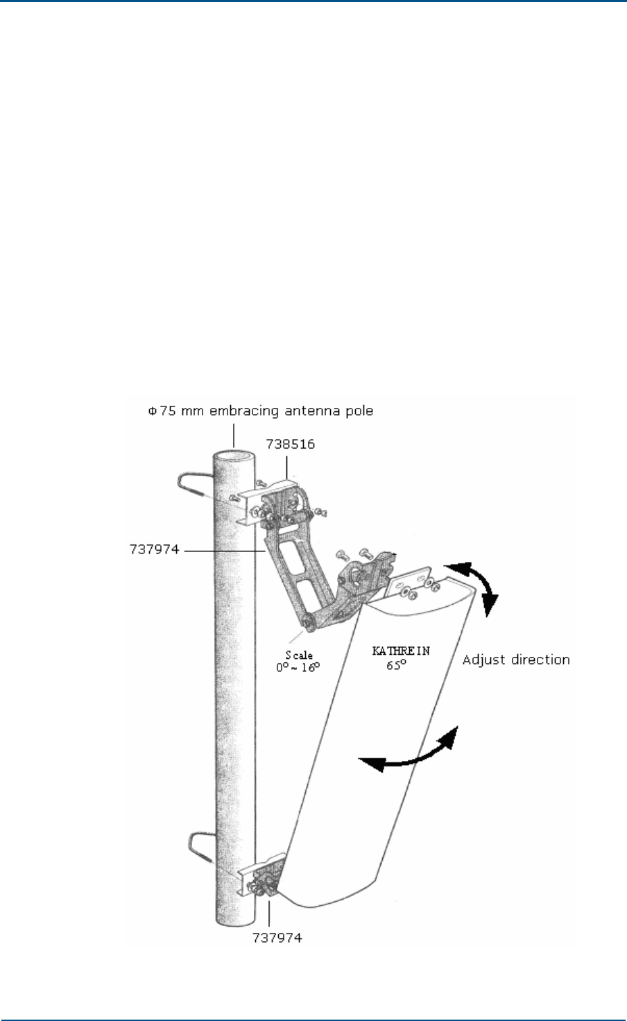
Uni-Directional Antenna Installation
This section describes Kathrein antenna installation procedure. Follow
installation instructions provided with antenna.
Take following steps to install uni-directional antenna:
1. Assembling antenna accessories
Directional antenna has a number of installation fasteners. Follow
instructions provided along with antenna. For example, Kathrein
antenna has two types of fasteners: 738516 and 737974. Before fixing
antenna, assemble fastener 737974 to antenna ends and then connect
fasteners 737974 and 738516. Install all accessories with spring and
flat washers. Fix antenna angle adjustment accessories to antenna
under the tower.
Figure 45 illustrates Kathrein antenna installation process.
FIGURE 45 - KATHREIN ANTENNA INSTALLATION
ZXC10 CBTS O1 Hardware Installation Manual
68 Confidential and Proprietary Information of ZTE CORPORATION
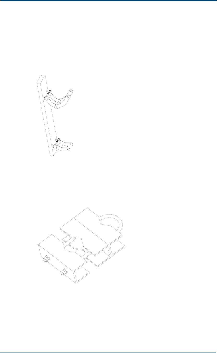
2. Fastening antenna onto the pole
Fix uni-directional antenna with accessories installed onto antenna pole.
Do not tighten screws to facilitate possible azimuth adjustment and tilt.
Figure 46 shows antenna fixing supports.
FIGURE 46 - ANTENNA FIXING SUPPORT
Adjust antennas to appropriate height, Figure 47 shows use U-shaped
bolts to fix antenna tilt angle, so that input and output ports of
antennas face downwards.
FIGURE 47 - U-SHAPED BOLT
Chapter 5 - Main Antenna Feeder System Installation
Confidential and Proprietary Information of ZTE CORPORATION 69
3. Adjusting antenna azimuth
Take following steps to adjust antenna azimuth.
i. Determine antenna azimuth using a compass and installation
direction according to engineering design drawing.
ii. Turn antenna slightly to adjust direction. At the same time measure
antenna direction with a compass to minimize error (generally not
more than 5°).
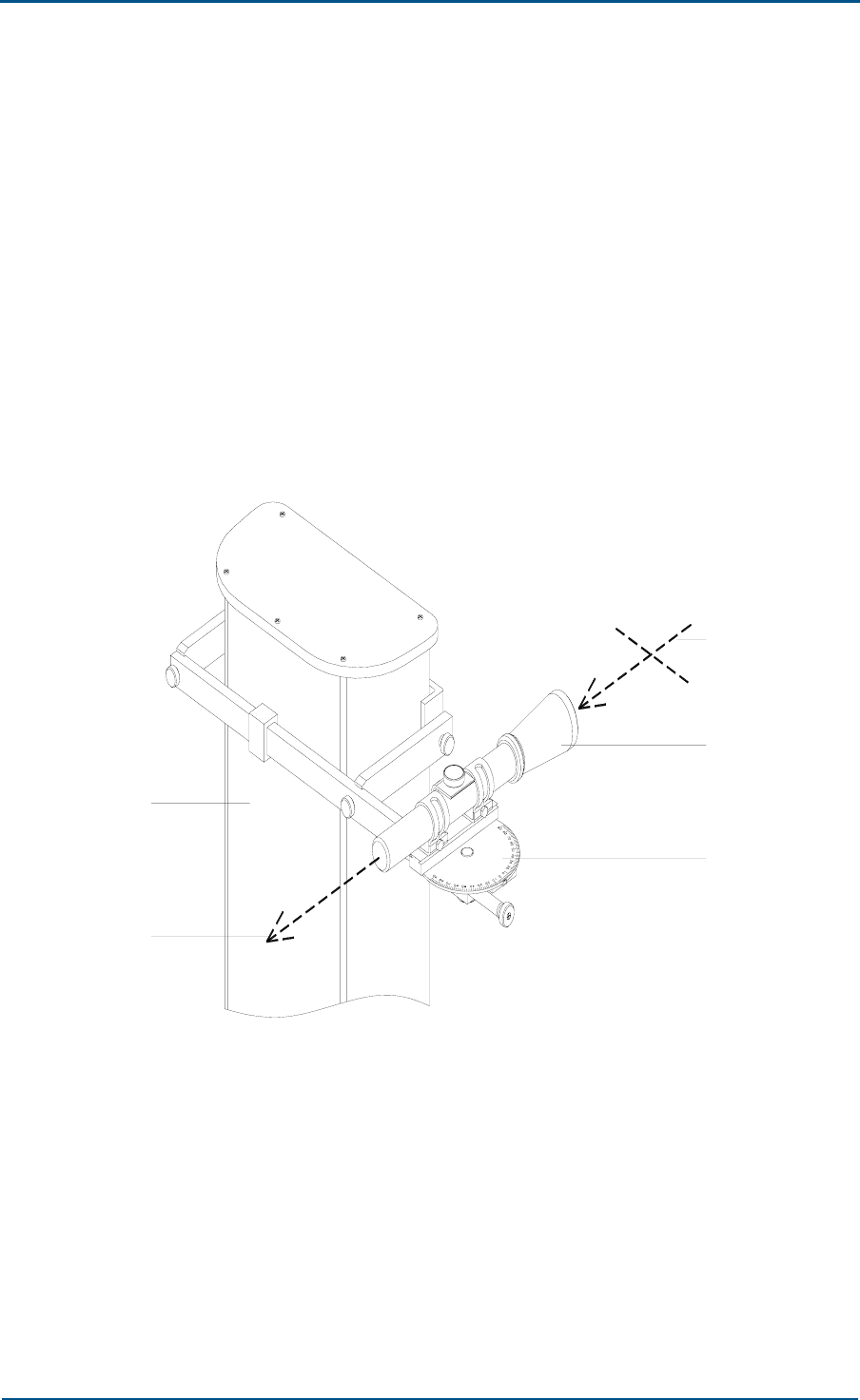
iii. Put special adjusting tool on antenna, aiming at target through
telescope, and turn antenna to acquire designed angle. Figure 48
shows this process.
iv. Tighten fastener 738516, after adjusting antenna azimuth.
FIGURE 48 - AZIMUTH ADJUSTING TOOL
5
4
3
2
1
1. Antenna 2. Target direction
3. Observation direction 4. Telescope
5. Dial
ZXC10 CBTS O1 Hardware Installation Manual
70 Confidential and Proprietary Information of ZTE CORPORATION
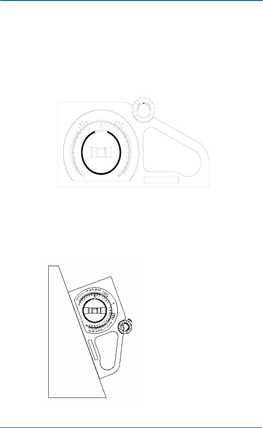
4. Adjusting antenna tilt
Take following steps to adjust antenna tilt
i. Adjust tilt meter angle required by the engineering design.
ii. Turn antenna top slightly and hold antenna from its top. Adjust tilt,
till the bead is centered and adjusted tilt meter is next to antenna.
Figure 49 shows angle gauge.
FIGURE 49 - AZIMUTH GAUGE
0
10
20
30
40
50
60
70
80
90
80
70
60
50
50
60
70
80
90
80
70
60
50
40
30
20
10
4
3
2
1
0
5
7
6
8
8
7
6
5
4
3
2
1
0
1
2
3
4
5
6
7
8
8
7
6
5
4
3
2
1
2
15
12
1
15
2
12
1
DIAL
Figure 50 shows detailed procedure:
Rotate dial to required set angle.
Press object to be measured against the dial chassis firmly, and move
them together until bubble in air bleeder stays in middle of two
indication rings.
FIGURE 50 - ADJUSTING TILT ANGLE
Chapter 5 - Main Antenna Feeder System Installation
Confidential and Proprietary Information of ZTE CORPORATION 71
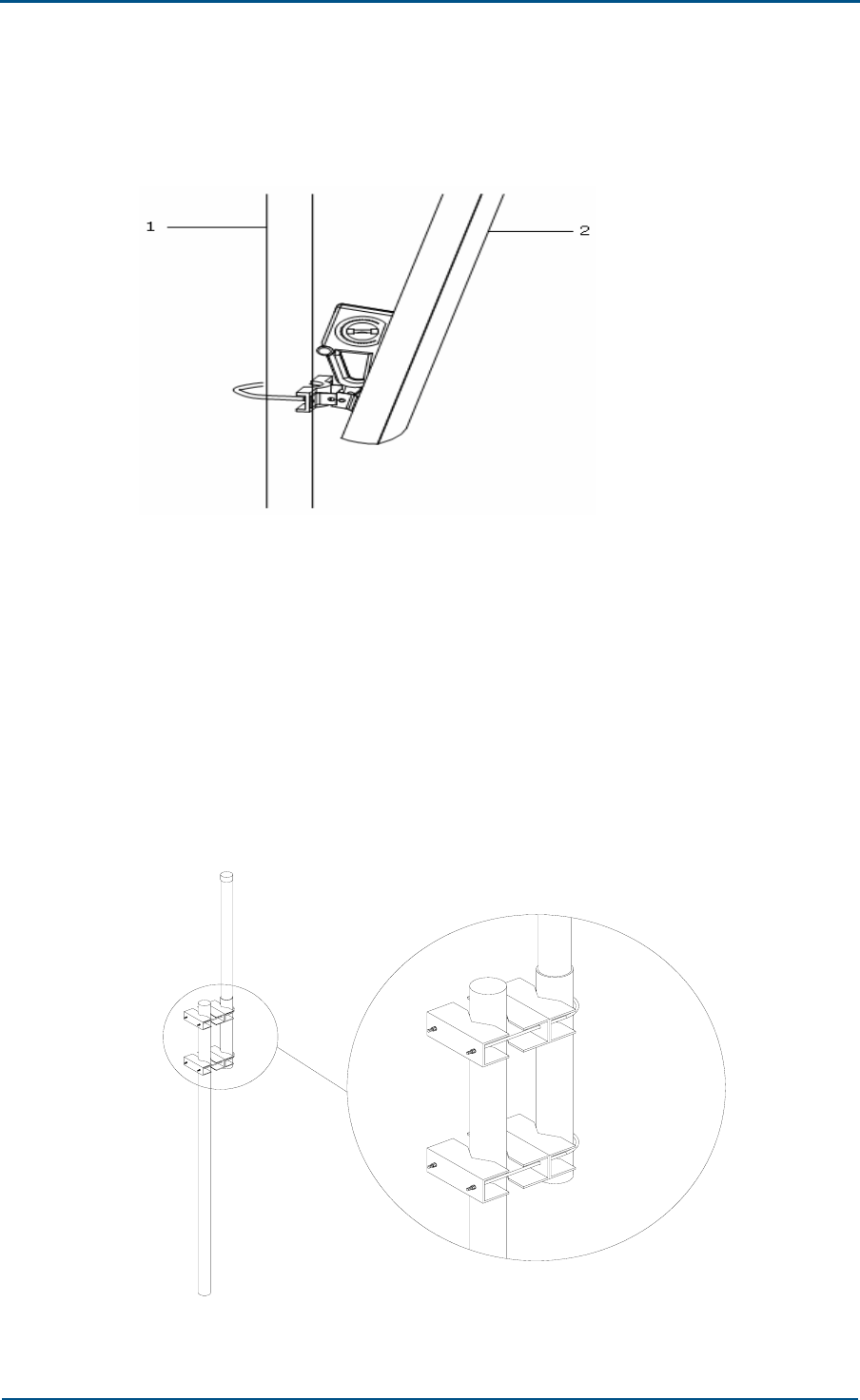
iii. After adjusting tilt, tighten the fastener 737974. Figure 51 shows to
adjust antenna tilt.
FIGURE 51 - ADJUSTING ANTENNA TILT
1. Antenna pole 2. Kathrein antenna
Omni-Directional Antenna Installation
Take following steps to install an omni-directional antenna:
1. Adjust antennas to appropriate height. Figure 52 shows to use U-
shaped bolts to fix antenna onto the antenna pole. Ensure that
antennas input and output ports face downwards.
FIGURE 52 - OMNI-DIRECTIONAL ANTENNA INSTALLATION
ZXC10 CBTS O1 Hardware Installation Manual
72 Confidential and Proprietary Information of ZTE CORPORATION
2. Measure verticality of antenna and ensure that antenna is vertical.
3. Fasten screws with a spanner.
Note:
To reduce working time at heights and to improve joint connection and
waterproof quality. Connect jumper and antenna, and conduct waterproof
treatment on the joint before fixing antenna on the pole.
Main Feeder Installation
Install the main feeder properly to minimize signal loss and for reliable
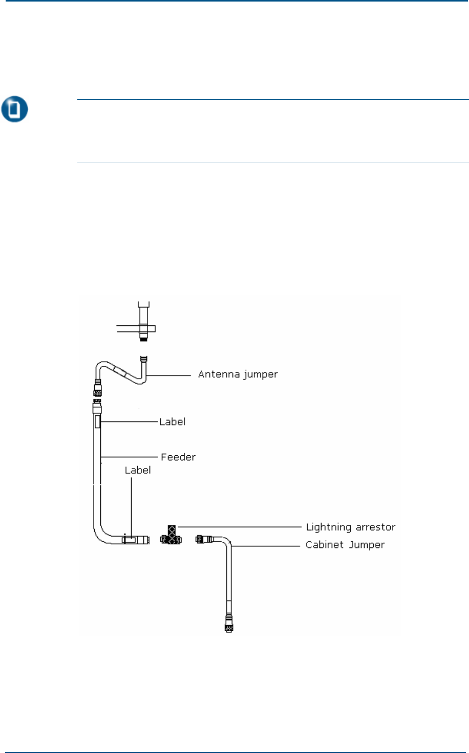
function. Figure 53 shows CBTS O1 main feeder overall structure.
FIGURE 53 - CBTS O1 MAIN FEEDER
Chapter 5 - Main Antenna Feeder System Installation
Confidential and Proprietary Information of ZTE CORPORATION 73
Antenna Jumpers Installation
Antenna jumper is a super-flexible jumper connecting antenna and main
feeder cable. Use 1/2" super-flexible jumper for BTS system. Jumper
connectors depend on antenna and main feeder cable. Usually, two
connectors are male DIN connectors.
Following section describes antenna jumper installation:
1. Select an appropriate path for jumper by taking into consideration
factors as: reliability, convenience, proper length and proper water
drainage.
2. Fix antenna connector and jumper with appropriate torque (typical
value for DIN connector is 1.7 N m ~ 2.3 N m). Figure 54 shows
connecting jumper.
FIGURE 54 - CONNECTING JUMPER
3. Similarly fix main feeder cable connector and jumper with an
appropriate torque.
4. Figure 55 shows to fix jumper with feeder cable clips with maximum
space of 29.921 inch (760 mm). Ensure minimum space between
feeder cable clips when wind speed is over 160 km/h.
FIGURE 55 - FIXING JUMPERS WITH FEEDER CABLE CLIPS
ZXC10 CBTS O1 Hardware Installation Manual
74 Confidential and Proprietary Information of ZTE CORPORATION
5. Ensure antenna and feeder cable performance and seal connectors with
waterproof self-adhesive tape and PVC tape.
While installing 1/2" super-flexible jumper, ensure following:
Minimum bending radius of one-time bend is 4.921 inch (125 mm).
Figure 56 shows one bend jumper.
FIGURE 56 - ONE BEND
Minimum bending radius of repeated bend is 7.87 inch (200 mm).
Figure 57 shows multiple bend jumpers.
FIGURE 57 - MULTIPLE BEND
Feeder Cable Installation
Connect main feeder cable to two jumpers, one to antenna and other to
cabinet using 7/8" foamed feeder cable. Both connectors are female DIN
connectors.
Ensure following mechanical properties while feeder cable installation:
Minimum bending radius of one-time bend is 15.74 inch (400 mm).
Minimum bending radius of repeated bend is 17.71 inch (450 mm).
Maximum hoisting length for feeder cable by the hoisting trawl is
2362.20 inch (60 m).
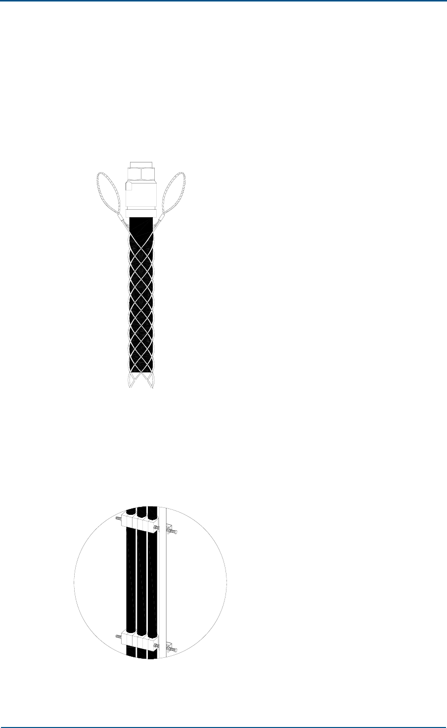
Chapter 5 - Main Antenna Feeder System Installation
Confidential and Proprietary Information of ZTE CORPORATION 75
Take following steps for feeder cable installation:
1. Ensure cable required length and cut off extra cable.
2. Prepare main feeder DIN connector at antenna side.
3. Use a pulley or hoisting trawl to hoist feeder cables to tower. Figure 58
shows hoisting trawl.
FIGURE 58 - CABLE HOISTING TRAWL
4. Make main feeder DIN connector at the other side.
5. Use feeder cable clips at every 47.24 inch (1.2 m), and add more
according to requirement, so that feeder lies closely against installation
pole. Figure 59 shows to fix feeder cable.
FIGURE 59 - FIXING FEEDER CABLE

ZXC10 CBTS O1 Hardware Installation Manual
76 Confidential and Proprietary Information of ZTE CORPORATION
6. For floor mounted BTS tower, ensure feeder cable is properly grounded
at 19.68 inch ~ 39.37 inch a (500 mm ~ 1000 mm) above the bend
where it connects antenna and leaves tower body, and outside the
entrance to the equipment room. For feeder cable longer than 2362.20
inch (60 m), ground it in the middle and connect its metallic outer
layer to grounding busbar through grounding kit. Lead a tin plated
copper wire with a cross section area more than 95 mm2 or zinc-plated
flat steel out of busbar to connect corresponding grounding tower point.
Ensure following while connector installation:
Keep feeder cable always straight.
Use special-purpose tools for cutting feeder cables.
Measure cable length precisely.
Use knife to strip the sheath of feeder cable avoid scratching external
conductor.
Keep plug-in components firm while tightening connector with spanner.
Turn connector fastener so that connector is fastened firmly.
Attach labels on both ends of main feeder cable before it is placed onto
the tower.
Lightning Arrester Installation
Connect all cables coming out of BTS antenna equipment room to lightning
arrester, which are connected to ground cable. There are various lightning
arresters, this section describes λ/4 stub as an example.
Take following steps to install lightening arrester:
1. Install lightning arrester between 7/8" main feeder cable and 1/2"
cabinet-top jumper after main feeder cable enters equipment room.
Lightening arrester has two DIN connectors, one is positive and other
is negative. Keep maximum installation torque for lightning arrester
with DIN connectors up to 25 N m, and with N connectors up to 1.7 N
m. Use adjustable torque spanner to adjust torque to specified value.
2. Lightning arrester has four RF ports, which connects to 7/8" main
feeder cable and 1/2" cabinet-top jumper. RF ports can be connected
either to antenna or to BTS, which provides protection against lightning.
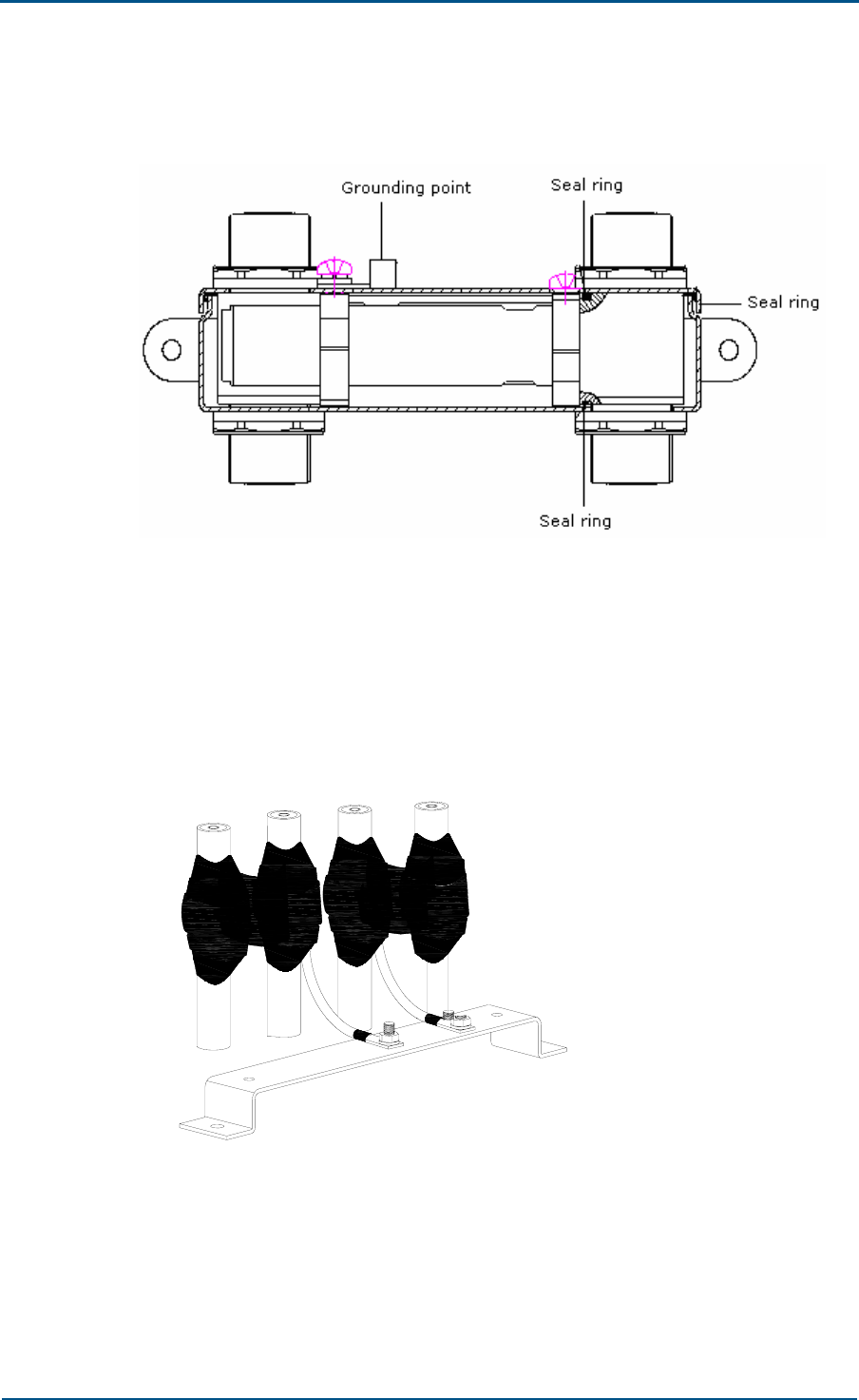
Chapter 5 - Main Antenna Feeder System Installation
Confidential and Proprietary Information of ZTE CORPORATION 77
Figure 60 shows lightning arrester side view.
FIGURE 60 - LIGHTNING ARRESTER SIDE VIEW
3. Connect lightning arrester grounding pole to main grounding pole or
system grounding ring, with a minimum possible grounding resistance.
4. Do not seal connectors before feeder cable performance test. Seal
connectors with self-adhesive tape if test result is satisfactory. Figure
61 shows this process.
FIGURE 61 - SEALING LIGHTNING ARRESTER
Lightning arrester installation precautions:
Do not expose RF ports outdoors.
During installation, make sure that all grounding contact surfaces are
clean, dry and not oxidized.
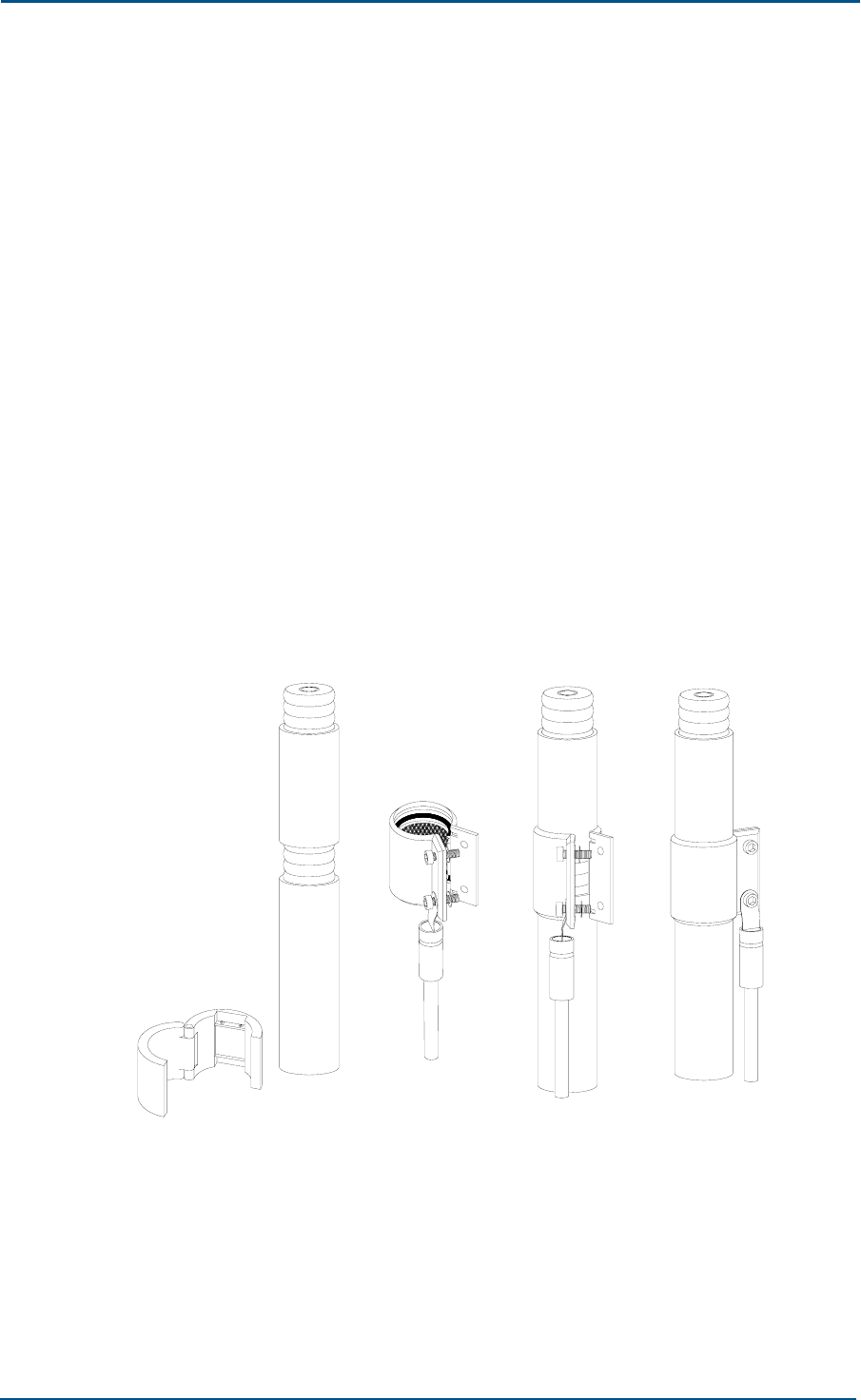
ZXC10 CBTS O1 Hardware Installation Manual
78 Confidential and Proprietary Information of ZTE CORPORATION
Make sure that grounding port of the lightning arrester is connected to
main grounding pole or grounding ring of system to ensure minimum
grounding resistance.
Install lightning arrester properly.
Make sure that working frequency marked on lightning arrester is
complies working frequency of BTS system.
Grounding Kit Installation
Grounding kit serves to connect feeder cable external conductor and tower
frame. Install grounding kit at feeder cable top near antenna and at feeder
cable end near tower bottom. For a feeder cable longer than 2362.20 inch,
connect a grounding clip in the middle.
Take following steps to install grounding kit:
1. Fix grounding kit grounding end. Mark corresponding position on 7/8"
feeder cable where grounding kit is installed, and strip 7/8" feeder
cable sheath at installation position.
2. Put grounding kit grip ring around feeder cable external conductor, and
then buckle the ring. Figure 62 shows this process.
FIGURE 62 - BUCKLING GRIP RING
3. Use waterproof self-adhesive tape to wrap entire connecting place.
Overlap each layer as half of the previous layer each time. Figure 63
shows this process. Keep wrapping direction same as buckling direction
of grip ring to make connection secure. Press adhesive tape along
grounding kit edge to make tape fit in closely with grip ring of
grounding kit.
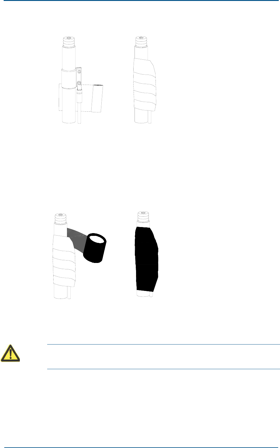
Chapter 5 - Main Antenna Feeder System Installation
Confidential and Proprietary Information of ZTE CORPORATION 79
FIGURE 63 - WINDING WATERPROOF ADHESIVE TAPE
4. Use electrically insulated tapes to wrap entire connecting place. Wind
in semi-overlapping mode so that one layer is 0.984 inch higher than
previous layer. Figure 64 shows this process. Overlap electrically
insulated adhesive taps by half that of previous for each loop. Pull tape
to a proper length to avoid folding. Press tape with both hands to make
sure that layers are in good contact.
FIGURE 64 - WINDING ELECTRICALLY INSULATED ADHESIVE TAPE
5. Connect grounding kit grounded end to tower body or special wiring
pole. Remove paint and oxide around connection place with a 0.511
inch radius (13 mm). Apply antioxidant grease to clean area to ensure
proper electrical contact.
Warning:
Never install grounding kit during lightning to avoid personal injury.

ZXC10 CBTS O1 Hardware Installation Manual
80 Confidential and Proprietary Information of ZTE CORPORATION
Cabinet Jumper Installation
Connect cabinet and main feeder cable by a 1/2" super-flexible feeder
cable. Jumper connector depends on cabinet and main feeder cable.
Usually both connectors are positive DIN connectors.
Connect antenna feeder jumper to one of fixed antenna feeder bases
(HYCOM1 ~ HYCOM6) on cabinet bottom.
Testing Antenna Feeder System
Test antenna feeder to check whether antenna matches feeder cable and
works properly. This test involves receiver and transmitter indexes. Main
tests are voltage standing wave ratio (VSWR) and RF transmit power test.
Ensure that following conditions are satisfied before antenna feeder
system test:
Antennas and feeder cables are installed and interfaces connected to
antennas are disconnected.
Feeder cable and connectors are in good condition and not damaged,
and connectors are connected properly, and antennas point to right
directions.
Connectors are not sealed with adhesive tapes.
Warning:
Avoid high-intensity microwave radiations during high-intensity RF signal
device operation.
Do not screw off connectors of transmitter output feeder or antenna feeder
cable during operation.
VSWR Test
VSWR test refers to voltage standing wave ratio (VSWR) test of TX
antenna. BTS tester SITE MASTER 332B is recommended for test. VSWR
must be smaller than 1.5 otherwise check antenna feeder system again.
BTS system generates primary and secondary alarms for VWSR more than
1.5.
RF Transmit Power Test
RF transmit power refers to average RF carrier power. Carry out RF
transmit power test to determine power at input end of combiner and
verify average transmit RF carrier power. Use site test instrument for test.
BTS tester MASTER 332B is recommended. Conduct test at input end of
combiner (output end of power amplification module).

Chapter 5 - Main Antenna Feeder System Installation
Confidential and Proprietary Information of ZTE CORPORATION 81
Waterproofing Connectors
Seal the connectors of each cable after ensuring that antenna feeder
system test is complete and result is OK. Use two types of adhesive tapes
for sealing: waterproof self-adhesive insulated tape and electrically
insulated adhesive tape. First wrap connectors with electrically insulated
adhesive tapes and then with waterproof adhesive tapes, and finally with
electrically insulated tapes again.
Electrically insulated adhesive tapes must be fire and cold-resistant and
corrosion-proof, and must be able to work under a voltage of 600 V.
Ensure maximum working temperature does not exceed 80°C.

Confidential and Proprietary Information of ZTE CORPORATION 82
Chapter 6
GPS Antenna Feeder System
Installation
This chapter describes GPS antenna feeder system installation:
GPS antenna feeder system structure
Installation position and requirements
Installation requirements
Lightning protection requirements
GPS connector preparation
NJ-9 GPS connector
GPS connector preparation procedure
GPS connector installation check
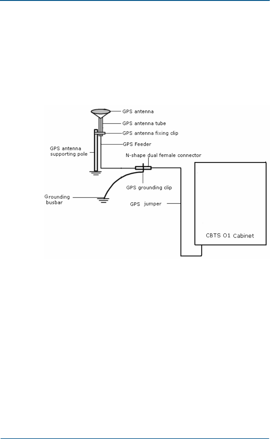
Chapter 6 - GPS Antenna Feeder System Installation
Confidential and Proprietary Information of ZTE CORPORATION 83
GPS Antenna Feeder System
Structure
Figure 65 shows GPS antenna feeder system composition.
FIGURE 65 - GPS ANTENNA FEEDER SYSTEM
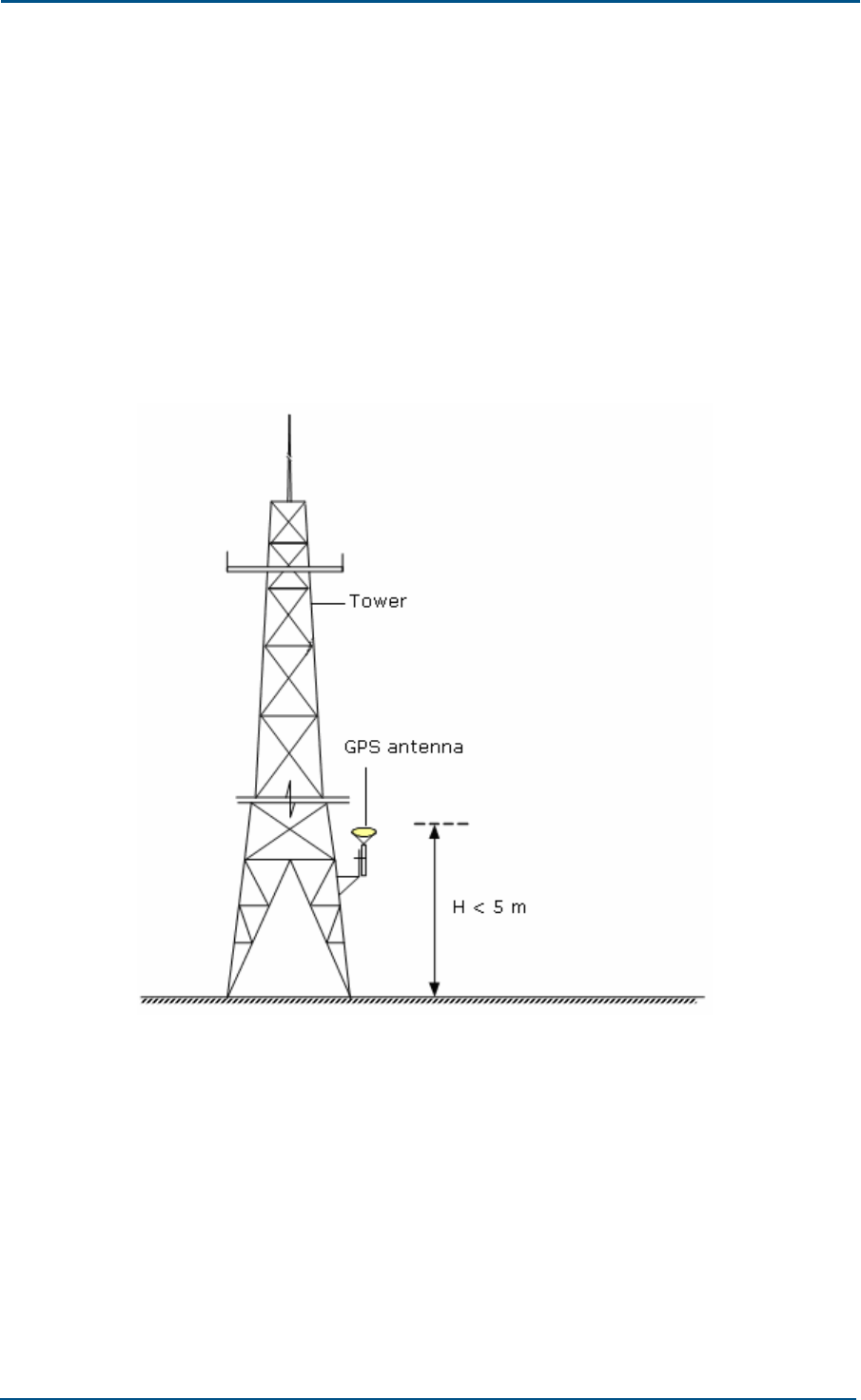
ZXC10 CBTS O1 Hardware Installation Manual
84 Confidential and Proprietary Information of ZTE CORPORATION
Installation Position and
Requirements
There are two types of GPS antenna installation positions:
Tower Mounted
Figure 66 shows position of a tower mounted GPS antenna.
FIGURE 66 - TOWER MOUNTED GPS ANTENNA
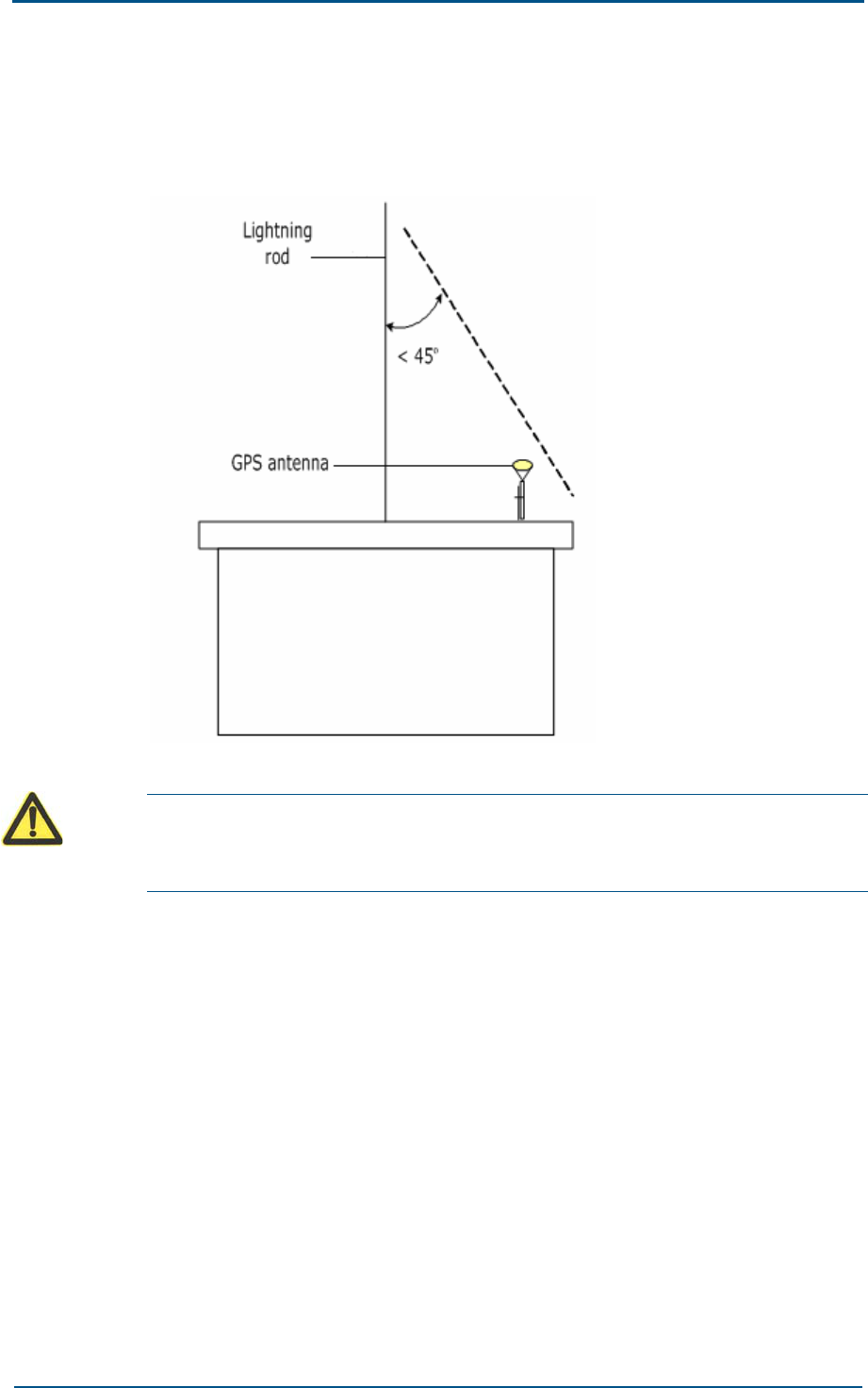
Chapter 6 - GPS Antenna Feeder System Installation
Confidential and Proprietary Information of ZTE CORPORATION 85
Roof Mounted
Figure 67 shows position of a roof mounted GPS antenna.
FIGURE 67 - ROOF MOUNTED GPS ANTENNA
Caution:
Both installation modes require that no obstacles are present in 150° GPS
antenna elevation.
Installation Requirements
Following are GPS antenna installation requirements:
GPS antenna installation position should have a broader view to track
on maximum satellites.
Keep coaxial cable short to reduce signal loss and lightning induction.
For a tower mounted GPS antenna, keep horizontal distance between
GPS pole and tower up to 11.81 inch (300 mm).
Do not install GPS antenna under microwave antenna, high-voltage
lines, television transmitting tower, or within radiation range of a
mobile system antenna.
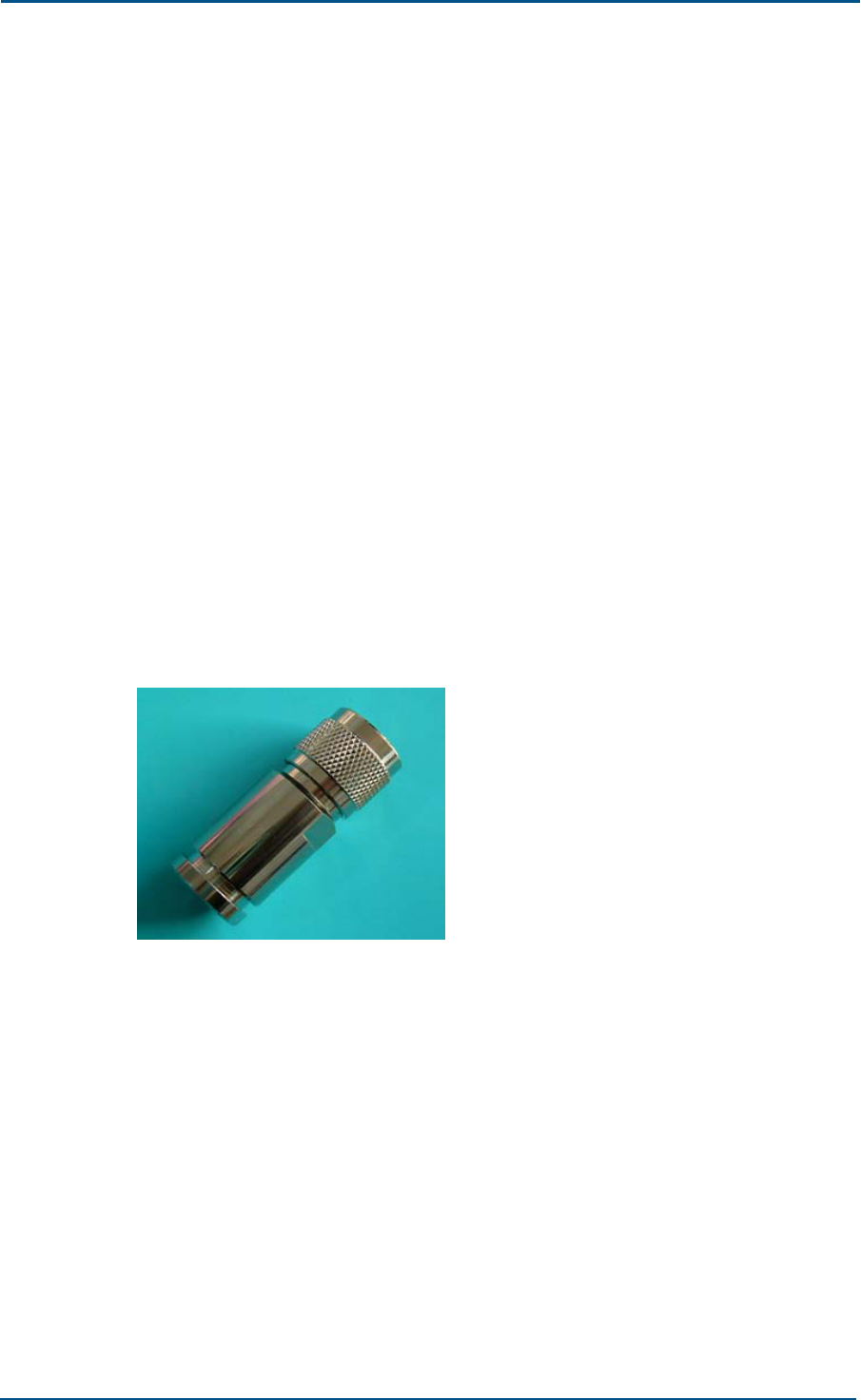
ZXC10 CBTS O1 Hardware Installation Manual
86 Confidential and Proprietary Information of ZTE CORPORATION
Lightning Protection Requirements
Following are lightning protection requirements to install a GPS antenna:
Install GPS antenna within 45° lightning protection coverage area of
tower. Otherwise, install a special lightning arrester for the GPS
antenna.
Place GPS antenna away from lightning strikes. If it is tower mounted,
install it in a safe place on the roof or in tower lower part.
Ensure that pole supporting GPS antenna is grounded.
NJ-9 Connector Preparation
This section describes NJ-9 GPS connector preparation procedure:
NJ-9 Connector
For GPS feeder cables shorter than 80 m use NJ-9 GPS connector. Figure
68 shows NJ-9 GPS connector.
FIGURE 68 - NJ-9 GPS CONNECTOR
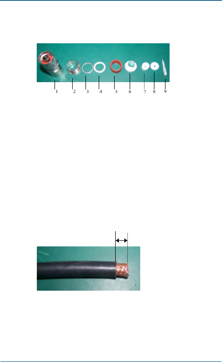
Chapter 6 - GPS Antenna Feeder System Installation
Confidential and Proprietary Information of ZTE CORPORATION 87
Figure 69 shows NJ-9 GPS connector parts.
FIGURE 69 - NJ-9 GPS CONNECTOR PARTS
1. Shell 2. Tail connector
3. Air proof washer 1 4. Air proof washer 2
5. Air proof washer 3 6. Insulating washer
7. Insulating washer 8. Insulation plate
9. Inner conductor pin
Connector Preparation Procedure
Take following steps to prepare GPS connector:
1. Stripping GPS cable shell
Use sharp knife to strip GPS cable outer covers about 0.41 inch ±
0.009 inch (10.5 mm ±0.25 mm). Avoid damaging inner copper wires.
Figure 70 shows stripped cable.
FIGURE 70 - STRIPPING GPS CABLE
±
10.5 mm 0.25 mm
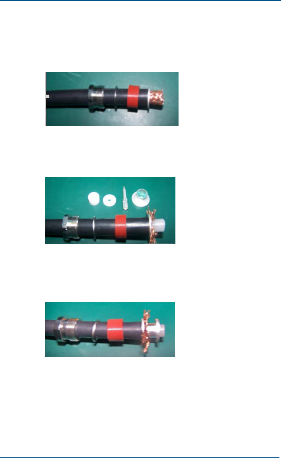
ZXC10 CBTS O1 Hardware Installation Manual
88 Confidential and Proprietary Information of ZTE CORPORATION
2. Installing connector outer parts
Assemble all NJ-9 outer parts from left to right on cable. Figure 71
shows external conductor assembly.
FIGURE 71 - EXTERNAL CONDUCTOR ASSEMBLY
Stretch copper wires back at one end to metal washer. Figure 72
shows white shielded layer after stretching copper wires.
FIGURE 72 - SHIELDED LAYER
Put sliver coated flange between shielded layer and insulation layer.
Finally adjust shielded layer between flange and metal washer. Figure
73 shows inserting external conductor flange.
FIGURE 73 - INSERTING EXTERNAL CONDUCTOR FLANGE
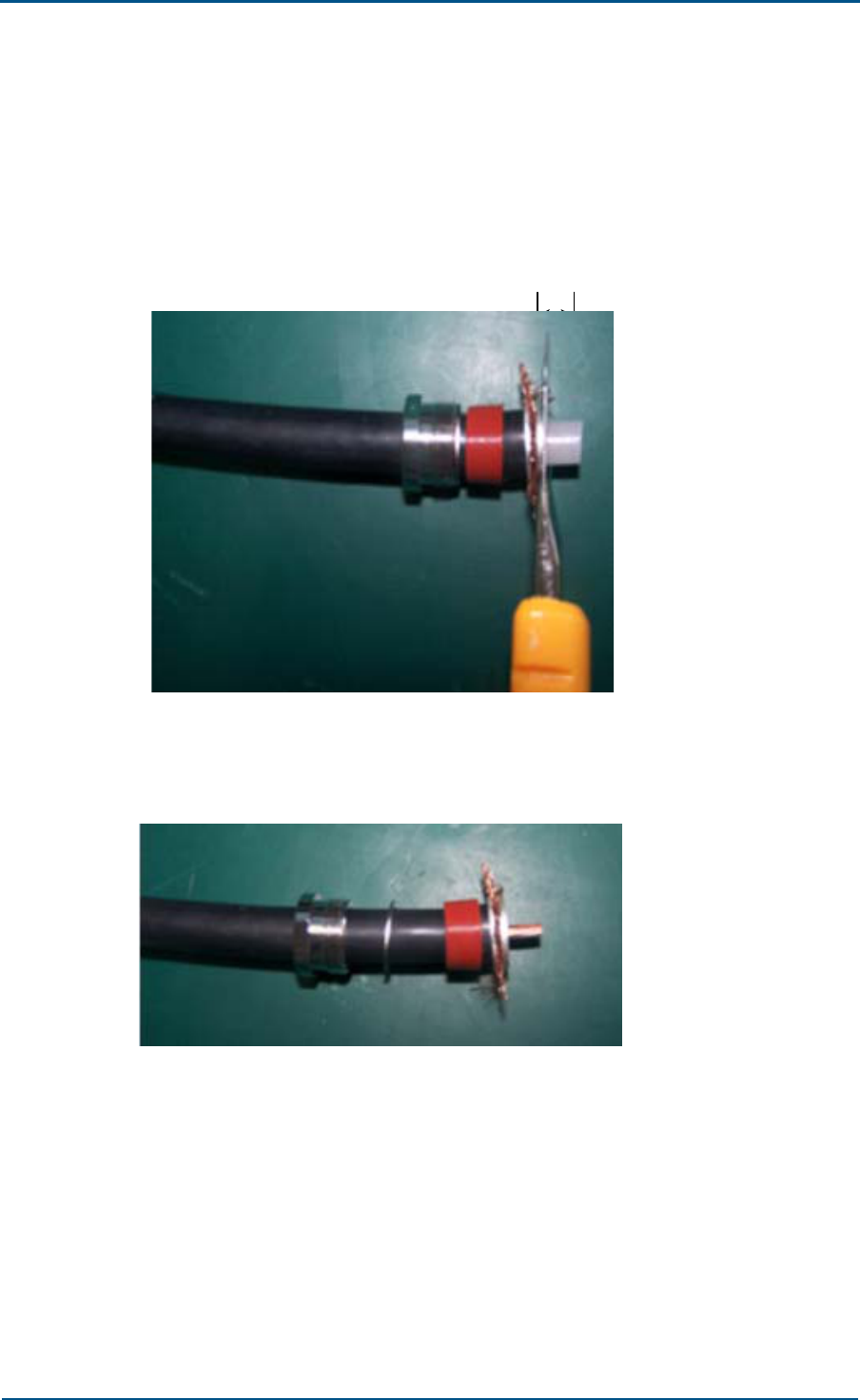
Chapter 6 - GPS Antenna Feeder System Installation
Confidential and Proprietary Information of ZTE CORPORATION 89
3. Stripping insulation layer
Strip insulation layer so that copper core appears. Avoid damaging
copper core and cut insulation layer at equal lengths. Keep outer
copper core length between 0.27 inch to 0.287 inch (7 mm to 7.3 mm).
Figure 74 shows stripping insulation layer.
FIGURE 74 - STRIPPING INSULATION LAYER
7.0 mm ~ 7.3 mm
Figure 75 shows cable after stripping insulation layer.
FIGURE 75 - AFTER STRIPPING INSULATION LAYER
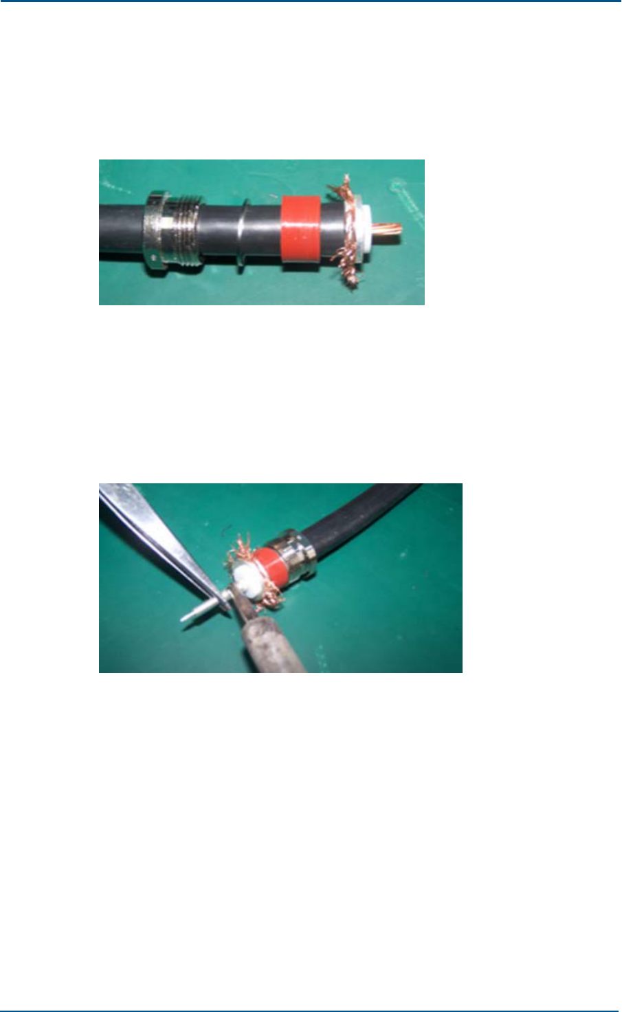
ZXC10 CBTS O1 Hardware Installation Manual
90 Confidential and Proprietary Information of ZTE CORPORATION
4. Welding inner conductor pin
Insert white insulation plate till it touches flange tightly. Figure 76
shows insulation plate insertion.
FIGURE 76 - INSERTING INSULATING PLATE
Melt a very thin layer of tin (Sn) and cover copper core homogeneously.
For fixed temperature iron, adjust temperature to 350 degree Celsius
and keep it for 10 seconds. For normal iron add more time till tin is
melted properly. Insert copper core into pin tail hole. Ensure that pin
tail touches insulation plate. Use iron to raise temperature when
required. Figure 77 shows welding inner conductor pin.
FIGURE 77 - WELDING INNER CONDUCTOR PIN
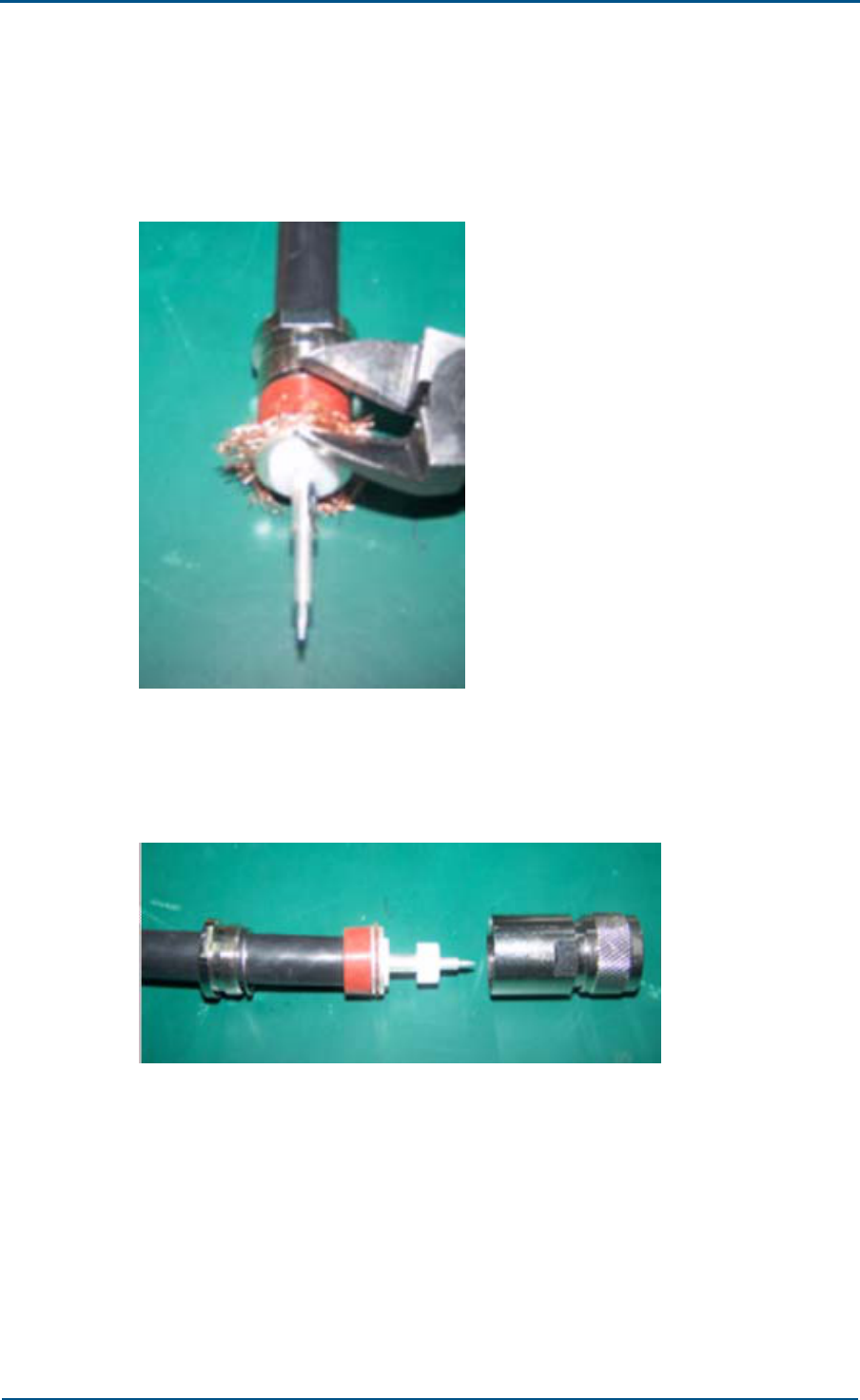
Chapter 6 - GPS Antenna Feeder System Installation
Confidential and Proprietary Information of ZTE CORPORATION 91
5. Cutting Shielded layer
Use plier to cut copper wires on shielded layer. Figure 78 shows this
process.
FIGURE 78 - CUTTING SHIELDED LAYER
Plug pin into white supporting ring and assemble shell and cable.
Figure 79 shows this process.
FIGURE 79 - ASSEMBLING SHELL AND CABLE
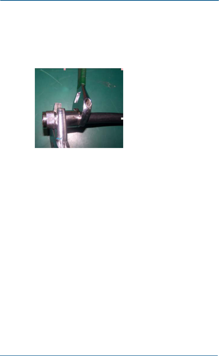
ZXC10 CBTS O1 Hardware Installation Manual
92 Confidential and Proprietary Information of ZTE CORPORATION
6. Shell tightening
Put a piece of cloth between wrench and shell, use wrench to tighten
shell and tail connecting parts. Figure 80 shows this process. Ensure
that torque lies in the range of 98 Nm to 120 Nm and pin is at one
level inside the cable.
FIGURE 80 - SHELL TIGHTENING
GPS Connector Installation Check
After GPS cable installation check following:
Pin should be at same level inside the shell.
Connector strength must be more than 60 N.
Insulation resistance between pin and shell must be more than 5000 M
ohms.
Check resistance between feeder cable pins and conductors head.
Check resistance between conductors head.

Chapter 6 - GPS Antenna Feeder System Installation
Confidential and Proprietary Information of ZTE CORPORATION 93
This page is intentionally blank.

Confidential and Proprietary Information of ZTE CORPORATION 94
Chapter 7
Board Installation
This chapter describes CBTS O1 board installation:
Installation flow chart
Installation procedure and precautions
Installation precautions
CBTS O1 board slot
RFS board installation
BDS boards installation
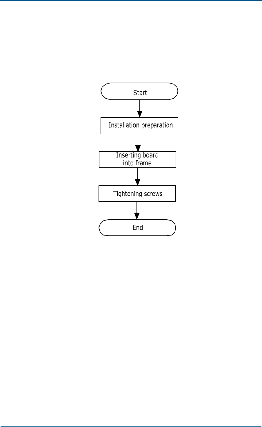
Chapter 7 - Board Installation
Confidential and Proprietary Information of ZTE CORPORATION 95
Installation Flow Chart
Figure 81 shows board installation flow chart.
FIGURE 81 - BOARD INSTALLATION FLOW CHART
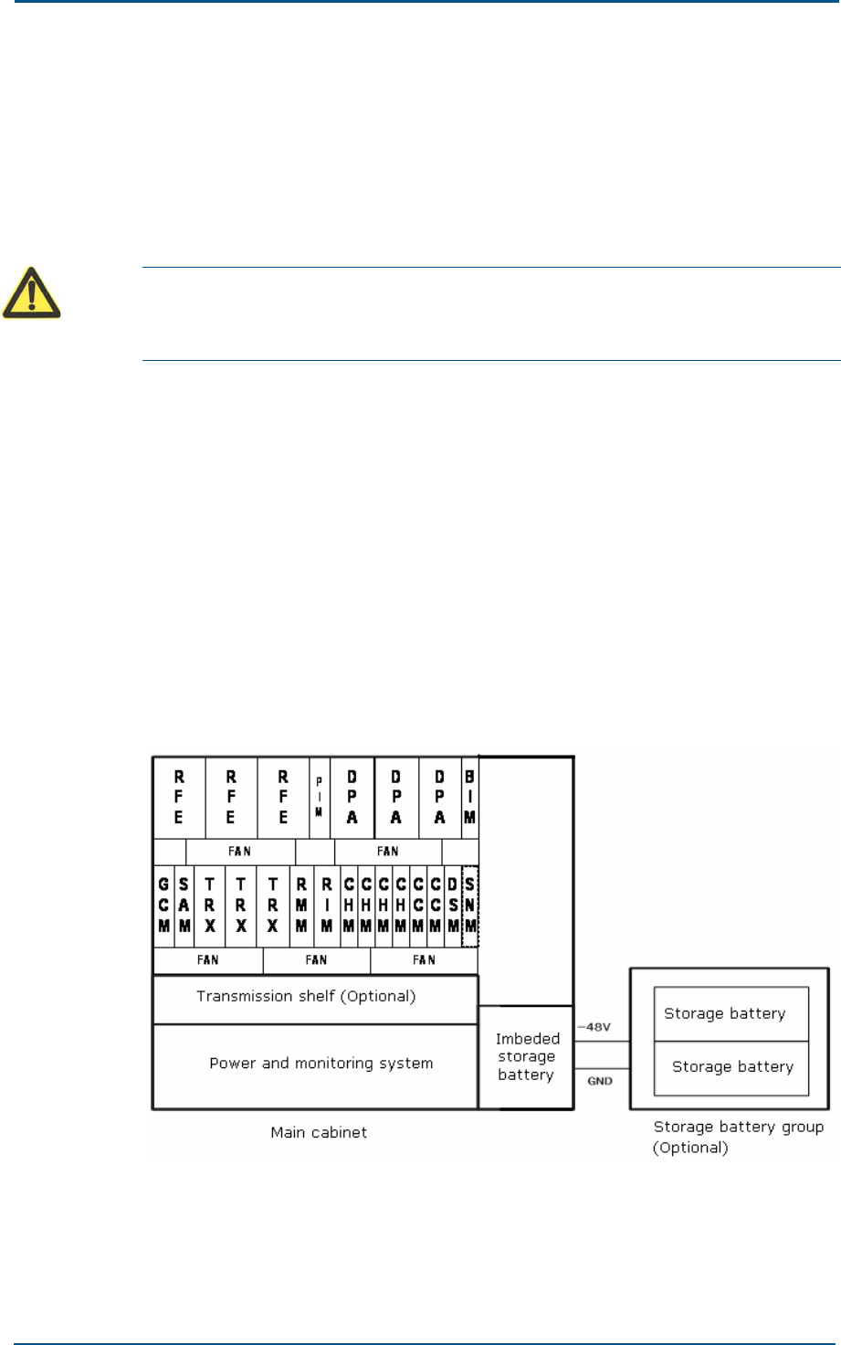
ZXC10 CBTS O1 Hardware Installation Manual
96 Confidential and Proprietary Information of ZTE CORPORATION
Installation Procedure and
Precautions
This section describes board installation in different plug-in boxes.
Caution:
Ensure power is switched off before board installation. Only TRX and RFE are
hot pluggable.
Installation Precautions
Take following precautions while board installation:
Ensure anti-static wrist strap is grounded before operation.
Ensure that slots for installing boards are consistent with required slots.
To avoid damage, push boards slowly along the guide rail.
CBTS O1 Board Slot
Figure 82 shows CBTS O1 board slot.
FIGURE 82 - CBTS O1 BOARD SLOT

Chapter 7 - Board Installation
Confidential and Proprietary Information of ZTE CORPORATION 97
RFS Board Installation
Take following steps to install RFS boards:
1. Wear anti-static wrist straps.
2. Take boards out of anti-static bags and check damaged parts.
3. Select slot position for board installation.
4. Gently insert board vertically along the guide slot.
5. Lock board by pressing down ejector lever.
BDS Board Installation
Take following steps to install BDS board:
1. Preparations
Before installation, take board out of antistatic bag and check them. If
any damages are found, register fault types, and pack them for repair.
2. Board insertion in plug-in box.
While board insertion, determine board type and its slot, keep ejector
lever in de-locking position. Push board along guide rail slowly into slot.
Figure 83 shows to push board along guide rails till it reaches bayonet
of extraction tool.
FIGURE 83 - BOARD PLUGGING (STEP 1)

ZXC10 CBTS O1 Hardware Installation Manual
98 Confidential and Proprietary Information of ZTE CORPORATION
Push board forward and turn down extraction tool ejector levers on
both sides. A click indicates that extraction tool is in the position and
its ejector levers are hooked. Figure 84 shows this process.
FIGURE 84 - BOARD PLUGGING (STEP 1)
3. Tightening screws
Tighten captive screws on extraction tools with flathead or Philips
screwdrivers. Figure 85 shows this process.
FIGURE 85 - BOARD PLUGGING (STEP 3)
Note:
To uninstall a board follow the reverse process that of board installation.

Chapter 7 - Board Installation
Confidential and Proprietary Information of ZTE CORPORATION 99
This page is intentionally blank.

Confidential and Proprietary Information of ZTE CORPORATION 100
Chapter 8
Hardware Installation Check
This chapter describes CBTS O1 hardware installation check:
Cabinet installation check
Cabling rack installation check
Cable installation check
Power and grounding cables
Trunk and RF cables
Board and sensor installation check
Antenna and GPS feeder system installation check
1/2” indoor jumper
Lightning arrester
Primary and GPS feeder
Three-way feeder clamp
1/2” outdoor jumper
Antenna
Feeder SWR
Environment check

Chapter 8 - Hardware Installation Check
Confidential and Proprietary Information of ZTE CORPORATION 101
Cabinet Installation Check
Check following after CBTS O1 cabinet installation.
Ensure that cabinet installation location complies with the engineering
design drawing.
Erect cabinet firmly that must resist an earthquake measuring up to
7.0 on Richter scale.
Ensure that horizontal and verticality error and the gap between
adjacent bases is less than 3 mm.
Ensure all other equipment and cabinet front door are in one line.
Ensure cabinet front and rear parts are at a distance of 39.37 inch
(1000 m) and 31.49 inch (800 mm) away from the walls respectively.
Ensure that all cabinet components are present.
Ensure that all cabinet parts are fixed properly.
Ensure inside cabinet is clean and all screws are tight with flat washers
or spring washers.
Ensure each base is equipped with four insulation spacers and base
supporters are consistent with expansion screws holes.
Ensure small cover plates at cabinet top are pushed forward to cover
wire outlets.
Cabling Rack Installation Check
Ensure that:
Cabling rack location and height meet the engineering design
requirements.
Cabling rack is in good shape.
Cabling rack is laid out with a grounding cable.

ZXC10 CBTS O1 Hardware Installation Manual
102 Confidential and Proprietary Information of ZTE CORPORATION
Cable Installation Check
Check following CBTS O1 cables after installation.
Power and Grounding Cables
Check for following after laying power and grounding cables:
Ensure that the equipment room power and grounding cables are in
accordance with engineering design specifications.
PGND protective grounding wire on a CBTS O1 cabinet employs 35
mm2 yellowish green or yellow copper-core cable connected with
indoor PGND grounding copper bars.
Ensure that grounding cable is black copper core cable of 25 mm2, -48
V power cable is blue copper core cable of 25 mm2, and grounding bus
has a diameter more than 35 mm2.
Each grounding point on grounding copper busbar is connected with
one piece of equipment.
Protective grounding and AC neutral cables are laid out separately.
AC neutral line in power room is independently grounded.
The outdoor grounding resistance is less than 5 ohm.
Labels on both ends of power and grounding cables are correct.
Avoid cable overlapping. All lengthy cables must be shortened or well
coiled up.
Copper lugs on both ends of power and grounding cables are soldered
or pressed firmly.
Entire power and grounding cables are made from one material with no
connections in between.
Grounding busbar is insulated from walls and shortest possible
grounding cable is used.
Connection of power supply to cabinet terminals is correct.
Insulating protective sleeves are installed on both power supply
connecting terminals.
Power and grounding cables are not damaged.
Wires at connecting terminals and lug handle are properly insulated.
Connecting terminals are equipped with flat and spring washers.

Chapter 8 - Hardware Installation Check
Confidential and Proprietary Information of ZTE CORPORATION 103
Trunk and RF Cables
Ensure that:
Trunk cable connectors are properly installed, labelled and are not
loose.
Trunk cables have some margin for expansion.
Cable connector shell is properly connected with grounding system.
RF cables between modules in cabinet are properly connected.
Unused connectors are screwed on with a matching terminal.
RF cables between TRX, DPA and RFE are in parallel and ensure some
margin at bends.
Board and Sensor Installation
Check
Ensure that:
Slots for board installation comply with the engineering design.
Board screws on cabinet are tightened properly.
Board is properly connected with backplane.
Temperature and humidity sensor are vertically installed and cables
are properly connected to cabinet top.
Smog sensor is horizontally installed and cables are properly connected
to cabinet top.

ZXC10 CBTS O1 Hardware Installation Manual
104 Confidential and Proprietary Information of ZTE CORPORATION
Antenna and GPS Feeder
System Installation Check
Ensure that antenna and GPS feeder system are installed according to
engineering design specifications. Check for following after antenna and
GPS feeder system installation:
1/2” Indoor Jumper
Indoor jumper is properly connected to terminal on cabinet top.
Indoor jumpers are tidy, in appropriate length and bound on cabling
rack in order.
Jumpers are laid in layers according to sectors.
11.81 inch (300 mm) straight jumpers are connected between cabinet
and a lightning arrester.
Lightning arrester
RF lightning arrester is connected to feeder connector and fastened
tightly.
GPS lightning arrester 6 mm2 yellow grounding cable is properly
connected with outdoor grounding copper busbar.
RF and GPS lightning arresters are mounted between two crosspieces
of cabling rack without touching cabling rack.
Lightning arrester is insulated from cabling rack.
Lightning arrester rack grounding cable is grounded and routed to
outdoor grounding bar for reliable grounding.
Main GPS Feeder
Ensure the main feeder profile is flat and smooth. There are no copper
scraps in copper tube. Feeder connectors are connected tightly. Use a
special cutter to prepare main feeder connector.
7/8" feeder connector is installed properly and tightened well to avoid
any abnormal SWR caused by false connections.
Feeder between the tower top and the equipment room is grounded in
at least three points. Grounding points are bound firmly with proper
waterproof measures.
When tower is 2362.20 inch (60 m) above and needs a longer feeder,
place another feeder grounding clip in middle of the tower.
Feeder grounding clip terminals are fixed on steel plate of a nearby
tower.

Chapter 8 - Hardware Installation Check
Confidential and Proprietary Information of ZTE CORPORATION 105
Outer grounding copper busbar employs a special reliable path to an
underground ground grid. The line width is more than 50 mm2.
For a building without a tower, antenna feeder ground at top is
connected with nearby lightning protection ground grid on the roof.
Feeder grounding cable is led from top to bottom. Separation angle
between feeder and grounding cable is no more than 15º.
Feeder cabling has no crisscrossing. Cables are arranged properly
without twists and turns.
Minimum bending radius of feeder is no more than 20 times the feeder
radius, and bending radius of main feeder is more than 11.81 inch
(300 mm).
Main feeder cabling is well planned. Main feeders within a sector are
arranged in a row and column consistently.
Two name labels are bound on both feeder terminals, to ensure that
feeders correspond to antennas with corresponding lengths on a feeder
name plate.
There is no dry joint in soldering GPS core wire.
GPS copper core and outer layer are not short-circuited.
GPS feeder connectors are tight.
Three – Way Feeder Clamp
Three-way feeder clamp is fixed on outdoor cabling rack.
Intervals between feeder fixed clips are even and in same direction.
A feeder clamp is installed every 59.05 inch on primary feeder.
1/2” Outdoor Jumper
Antenna and 1/2" jumper, 1/2" jumper and main feeder are properly
connected, connector threads are tightened and wrapped with
waterproof adhesive tape.
Jumper and antenna are parallel to each other with 11.81 inch (300
mm) distance in between at the joint.
All outdoor jumper connectors are made waterproof and jumper is
equipped with a waterproof curve.

ZXC10 CBTS O1 Hardware Installation Manual
106 Confidential and Proprietary Information of ZTE CORPORATION
Antenna
Antenna support and tower are properly installed.
Antenna model is according to networking planning design.
Actual hanging height of an antenna is according to network planning
design.
RF and GPS antennas are included in the protection area of a lightning
arrester (area within 450 down tilt from lightning arrester).
Azimuth of antenna is according to network planning. Azimuth error of
directional antenna is no more than 50.
Actual mechanical down tilt of an antenna is according to network
planning and two uni-polarization antennas have same down tilts.
Actual electrically controlled down tilt of an antenna is according to
network planning and two uni-polarization antennas have consistent
down tilt.
All antenna poles are firmly installed and properly grounded. Vertical
error is less than 20. All antennas must be vertical to ground.
Receive/transmit horizontal interval of an omni-directional antenna is
not less than 137.79 inch (3.5 m).
An omni-directional antenna is at least 59.05 inch (1.5 m) away from
the tower while a directional antenna is at least 39.37 inch (1 m) away
from the tower.
While installing an omni-directional antenna on a roof, horizontal
interval between omni-directional antenna and antenna lightning
arrester is not less than 98.42 inch (2.5 m).
An omni-directional antenna installed on a roof avoids blind area.
Main diversity antennas match each other within the sectors and the
set top jumpers on the rack.
Diversity distance is 137.79 inch (3.5 m) for 800 MHz system, 59.05
inch for 1.9G system, and 263.77 inch (6.7 m) for 450 MHz system.
Vertical interval between directional antennas within different sectors,
installed on same antenna support is more than 23.62 inch (0.6 m).
GPS spatial angle is more than 900.
While installing GPS antenna on building top, it is equipped with an
independent lightning arrester.
Feeder SWR
SWR is measured after antennas and all feeders are installed.
Indoor 1/2" jumper terminal is connected with an SWR tester for
testing. SWR should be less than 1.5.
Related Voltage Standing Wave Ratio (VSWR) value is specified, and a
VSWR test diagram is available.

Chapter 8 - Hardware Installation Check
Confidential and Proprietary Information of ZTE CORPORATION 107
Environment Check
Ensure that:
Outdoor engineering wastes are cleaned after the installation is over.
Front and rear doors and cabinet sides are cleaned.
Clean all fingerprint and other stains on cabinet surface.
Indoor unused materials are put away. Material in equipment room is
kept in order. Everything indoor is clean and tidy.
Any engineering waste materials are disposed off. Leave no cable clips
or sundries at the installation site.

Confidential and Proprietary Information of ZTE CORPORATION 108
Chapter 9
Power On and Off Mechanism
This chapter describes:
Power supply inspection
Precautions
Power-on procedure
Power-off procedure

Chapter 9 - Power On and Off Mechanism
Confidential and Proprietary Information of ZTE CORPORATION 109
Power Supply Inspection
Ensure following before powering on CBTS O1:
1. All boards are installed according to corresponding slot numbers and
configurations.
2. All boards are properly inserted into slots.
3. Cables between same and different racks (including cables on cabinet
backplane) are connected correctly.
4. Cables between CBTS O1 and BSC are connected correctly.
5. Input power supply is according to required values of 220 V.
Fluctuation range is 130 V ~ 300 V AND 110 V in range of 90 V ~ 140
V.
6. Antenna feeder is installed correctly.
7. Racks, antennas feeder cables and lightning arresters are properly
grounded.
8. All selection and control switches are set at specified start position.
Precautions
Avoid hot plugging of boards, wear anti static wrist strap when
required.
Unplug all boards gently.
Ensure right position of each board according to slot number.
Do not touch any component, connector or wiring slot when holding a
board.
Power-on Procedure
Take following steps to power on CBTS O1:
1. Ensure that various power switches are in OFF status.
2. Turn on AC power switch at cabinet bottom plate.
3. Turn on AC main switch AC MAIN SW of power subrack.
4. Turn on other switches of power subrack in following sequence:
AC heat exchanger, AC lighting, L1_L10 load, DC heat exchanger,
L12_transmission and battery.
5. Turn on breaker protection switch of each board one by one.
6. After powering on check indicators of each panel.

ZXC10 CBTS O1 Hardware Installation Manual
110 Confidential and Proprietary Information of ZTE CORPORATION
Caution :
If anything goes wrong in any of above steps shut down power supply
immediately, find fault and repeat the step again. Do not power on cabinet until
fault is removed.
Power-off Procedure
CBTS O1 power-off procedure is reverse of power-on procedure.

Chapter 9 - Power On and Off Mechanism
Confidential and Proprietary Information of ZTE CORPORATION 111
This page is intentionally blank.

Confidential and Proprietary Information of ZTE CORPORATION 112
Appendix A
Packing, Storage and
Transportation
This appendix describes:
Packaging
Cabinet packing
Cabinet packing procedure
Board packing
Board packing procedure
Base packing
Engineering material packing
Transportation
Storage
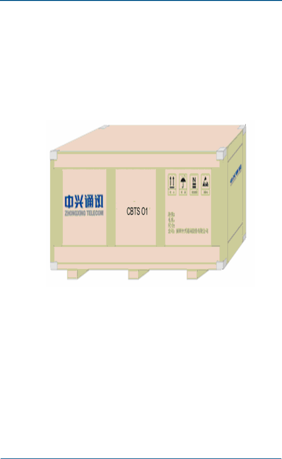
Appendix A - Packing, Storage and Transportation
Confidential and Proprietary Information of ZTE CORPORATION 113
Packaging
Following sections describes packing cabinet parts in a wooden box.
Cabinet packing
Figure 86 shows wooden box dimensions to pack cabinet.
FIGURE 86 - WOODEN PACKING BOX FOR CABINET
Pack RFE board in a paper packing box made for RFE boards. Pack TRX
and DPA boards in a universal paper packing box. Pack power board in a
universal paper packing box for parts. Pack the base in a paper packing
box made for base and put in a wooden packing box for parts.
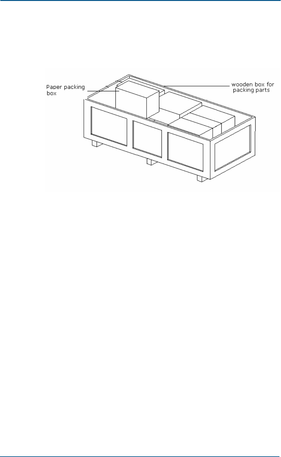
ZXC10 CBTS O1 Hardware Installation Manual
114 Confidential and Proprietary Information of ZTE CORPORATION
Figure 87 shows wooden box used for packing parts. Pack engineering
accessories in a universal external paper packing box and put them in a
wooden packing.
FIGURE 87 - WOODEN PACKING BOX FOR PARTS
Cabinet Packing Procedure
Follow procedure below to pack a cabinet:
1. Blow away dirt from cabinet and clean it with ethyl alcohol.
2. Put dustproof caps onto DB9 socket and N-type socket at the set top,
SAA socket and DB25 socket at E1 cable set top, and 17W2 female
sockets at the DPA layer.
3. Lay cabinet onto the ground covered with a foam cushion, with
cabinet door upward. Lower hook of an electric crane to a proper
location. Put nylon rope on the hook around 4 hanging points. Hoist
the hook to lift cabinet.
4. Open aluminum foil compound film bag and put cabinet into the bag.
5. Put a cushion into a wooden packing box, push wooden packing box
until it is under the hoisted cabinet and put the cabinet slowly into the
wooden box.
6. Put desiccant bags into aluminum foil compound film bag. To wrap
cabinet tightly by aluminum foil compound film bag, extract air in the
bag with a cleaner. Seal the aluminum foil compound film bag.
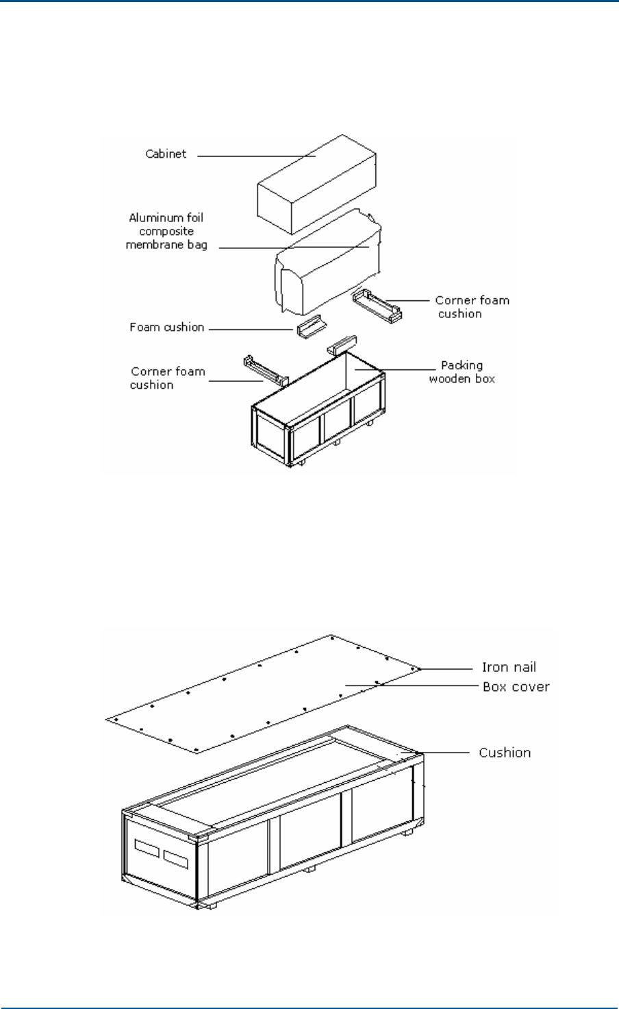
Appendix A - Packing, Storage and Transportation
Confidential and Proprietary Information of ZTE CORPORATION 115
7. Put cushions around cabinet and put cabinet into a wooden packing
box for cabinets, Figure 88 shows this process.
FIGURE 88 - CABINET PACKING
8. Seal a wooden packing box for cabinets. Put cushions around rack,
cover the box and drive nails into wooden case. Figure 89 shows
sealing a box.
FIGURE 89 - SEALING A BOX
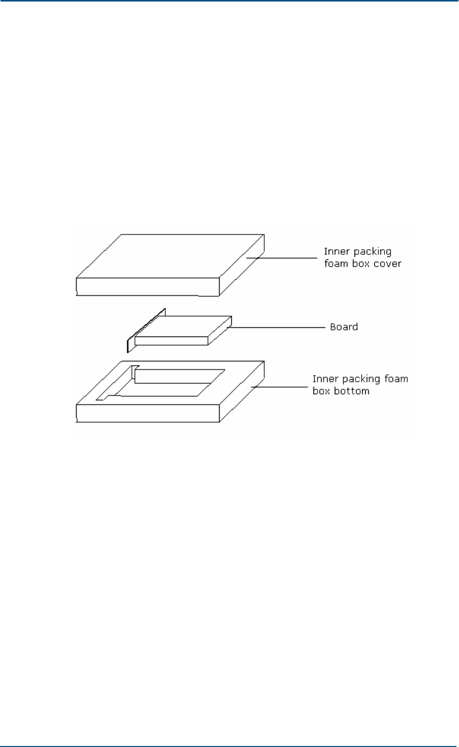
ZXC10 CBTS O1 Hardware Installation Manual
116 Confidential and Proprietary Information of ZTE CORPORATION
Board Packing
Before packing CBTS O1 cabinet, ensure to dismount heavy boards such
as RFE-RFE, RFE-DIV, DPA and TRX from the cabinet, which are packed
separately.
Board packing procedure
RFE, TRX and DPA Packing
Figure 90 shows that these boards are packed inside a packing foam
box first and then put in the packing boxes.
FIGURE 90 - INNER PACKING FOAM BOX
Board packing procedure is as follows:
i. Clean the board panels with alcohol.
ii. Place RFE, TRX and DPA boards into their own inner packing foam
boxes. Mark cover and bottom of foam box with silkscreen for
packing.
iii. After TRX and DPA boards are put into a foam box, put them into a
universal paper packing box made for boards. Figure 91 shows
packing box.
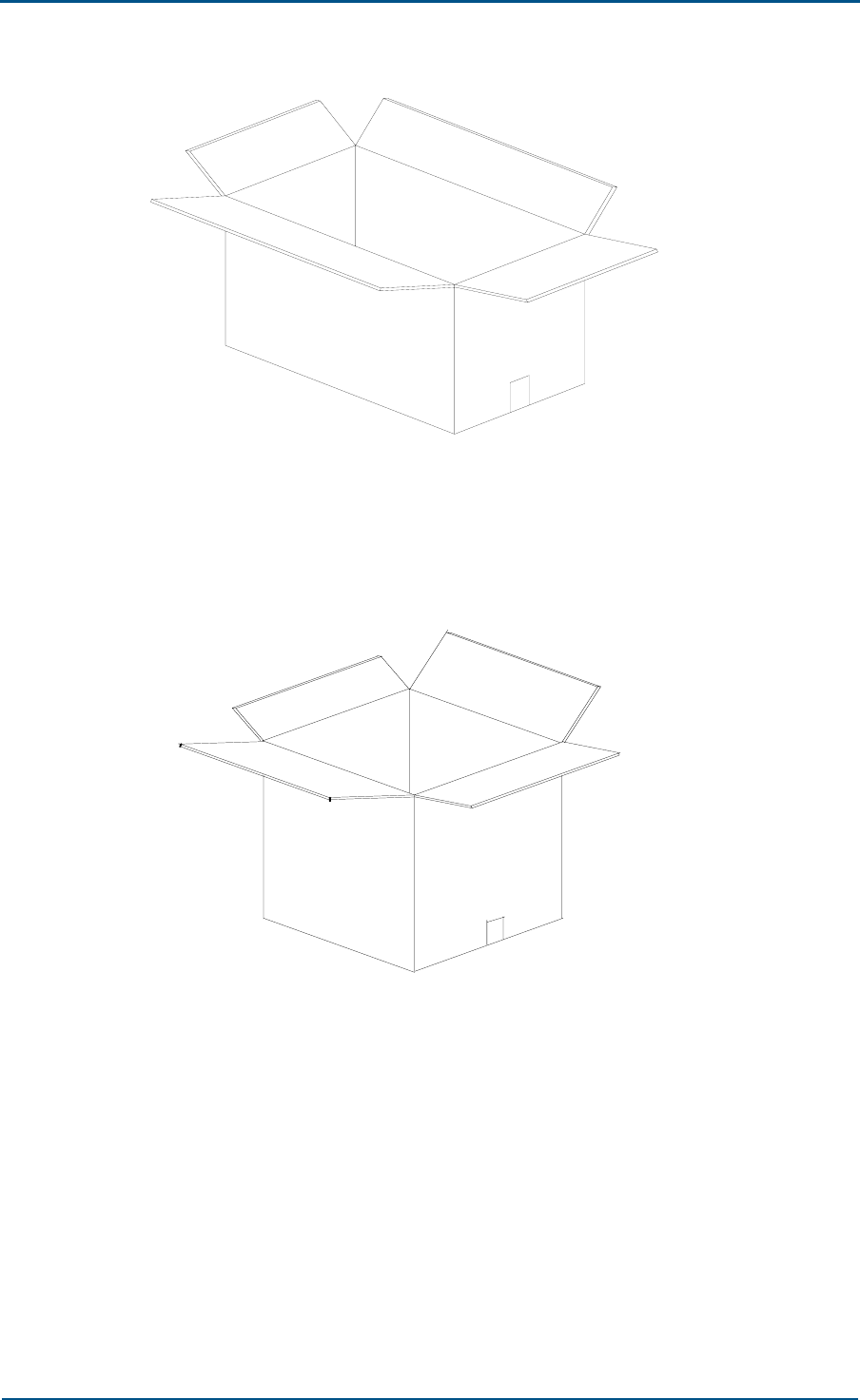
Appendix A - Packing, Storage and Transportation
Confidential and Proprietary Information of ZTE CORPORATION 117
FIGURE 91 - GENERAL PAPER PACKING BOX FOR BOARDS
iv. Put RFE board into a foam box and then into a paper packing box.
Figure 92 shows this box.
FIGURE 92 - PAPER PACKING BOX FOR RFE BOARDS
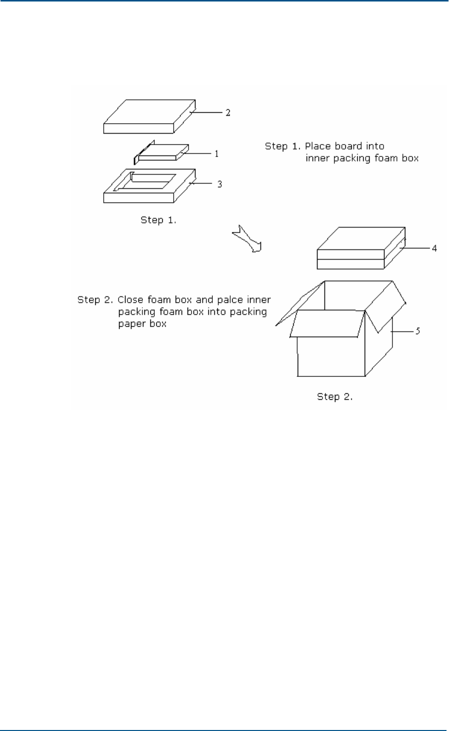
ZXC10 CBTS O1 Hardware Installation Manual
118 Confidential and Proprietary Information of ZTE CORPORATION
Figure 93 shows procedure for board packing.
FIGURE 93 - PACKING RFE, DPA AND TRX BOARD
1. Board 2. Inner packing foam box cover
3. Inner packing foam box bottom 4. Closed foam box
5. Paper packing box
v. Put packing list into a paper packing box and some packets of
desiccant.

Appendix A - Packing, Storage and Transportation
Confidential and Proprietary Information of ZTE CORPORATION 119
vi. Seal the box top with a tape according to H shape. Figure 94 shows
to put straps around the paper box at 3.39 inch (10 cm) away from
the end.
FIGURE 94 - SEALING AND PACKING
Base Packing
CBTS O1 cabinet base is packed in a paper packing box for base. Pack 8
M10 x 80 expansion bolts and washers in a small plastic bag and put into a
paper packing box for bases. After packing, put the paper packing box for
bases into a general wooden packing box for parts.
Engineering Materials Packing
Put engineering materials (such as antenna, power and transmission
cables, 1/2" jumper, GPS cable, three-way feeder clamp, and grounding
clip) into original paper packing boxes.
Put small engineering materials (such as the lightning arrester, adhesive
tape and connecting nose) into a general external paper packing box for
engineering accessories according to their quantity codes.
Seal above paper packing boxes and put them into a wooden packing box
for engineering accessories.

ZXC10 CBTS O1 Hardware Installation Manual
120 Confidential and Proprietary Information of ZTE CORPORATION
Transportation
Take following measure for equipment transportation:
Products are in a specified container and according to container
transportation marks.
There are no more than 3 layers for wooden packing box and 4 layers
for paper packing box. Sophisticated equipment is placed above and
others below. Centre of gravity height is no more than 78.74 inch (20
m), and vehicle is not overloaded.
Vehicle velocity is such to ensure safety based on road conditions.
Products are away from flammable, explosive or corrosive articles.
Protect equipment from rain, snow or other liquids, dirt, sunlight,
collision and materials with strong magnetism and radiation while
transportation.
Cover equipment with tarpaulin during open-air transportation.
In long-distance transportation, do not load equipment on an open ship
or carriage. In case of transhipment, do not store equipment in an
open storehouse.
Deliver and store precision instrument, meters, computers and
monitors according to moisture, shock and pressure-proof labels in the
packing box.
Always keep products upright.
Pay attention to safety while handling equipment. Ensure that only
skilled workers are operating the handling tools.
Storage
Take following measure for equipment storage:
Products and its components are in original packages.
Storage sites are clean, dry, and ventilated, with air-conditioning and
lighting facilities. Temperature and humidity range is according to the
requirement.
Equipment is not under direct sunlight.
Storehouse is equipped with moisture-proof, dustproof, shockproof and
corrosion-resistance facilities, and the corresponding antistatic facilities
for static-sensitive materials.
All goods are clean and in order with clear labels.
Keep a record of all equipment. Ensure goods location codes or other
necessary marks for the stored materials.

Appendix A - Packing, Storage and Transportation
Confidential and Proprietary Information of ZTE CORPORATION 121
Check stock conditions regularly. Update inventory record once a
month.
Install antistatic floorboards at warehouse entrance.
Place material in warehouses based on “First-in-first-out” principle.
Check equipment conditions by performing tests, if the product is
stored for more than six months.

ZXC10 CBTS O1 Hardware Installation Manual
122 Confidential and Proprietary Information of ZTE CORPORATION
Appendix B
SiteMaster Usage
This appendix describes SiteMaster usage:
Frequency range selection
SiteMaster check
Feeder input parameters
Tester installation
Measuring SWR
Measuring DTF
Note:
SiteMaster usage depends on model type used. Refer to device usage
documents attached for usage.

Appendix B - SiteMaster Usage
Confidential and Proprietary Information of ZTE CORPORATION 123
Frequency Range Selection
Take following steps to select a frequency range using SiteMaster:
1. Press <ON> to turn on SiteMaster meter.
2. Press <FREQ> on the main menu.
3. Press <F1> on the [Frequency] menu.
4. Input [Lower] frequency, such as 825 MHz, and press <Enter> for
confirmation.
5. Press <F1> on the [Frequency] menu.
6. Input [Higher] frequency, such as 880 MHz, and press <Enter> for
confirmation.
7. After confirmation, press [Main] to return to the main menu.
SiteMaster Check
Check the SiteMaster for frequency, environment and feeder parameters
changes. Take following steps to check:
1. Before check, ensure that input frequency range in SiteMaster is
correct.
2. Press <STARTCAL> to start check.
3. Press <Measuring OPEN>, <Measuring SHORT> and <Measuring
Load> as indicated to complete the check.
4. Include the extension cable attached with the meter to ensure
measurement accuracy.
Feeder Input Parameters
Take following steps to input feeder parameters:
1. Press <DIST>
2. Press <MORE>
3. Press <LOSS> to enter input feeder loss (dB) per meter. Press
<Enter> for confirmation.
4. Press <PROP V> to enter relative transmission rate. Press <Enter> for
confirmation.
5. Press <Main> to return to the main menu.

ZXC10 CBTS O1 Hardware Installation Manual
124 Confidential and Proprietary Information of ZTE CORPORATION
Tester Installation
Connect extension cables one end to RFE jumper connector inside the
cabinet and other end to Refl meter interface.
If active devices such as tower top amplifier or trunk amplifier are used for
feeder measurement, use jumpers to dodge it.
Measuring SWR
Take following steps to measure SWR:
1. Press <OPT>
2. Press <B1> and select [MODE]
3. Press <Up> or <Down> to choose <SWR> and press <Enter> for
confirmation.
4. Press <MAIN>to return to the main menu.
5. Input a proper frequency range if required.
6. Check meter if required.
7. Press <MAIN>to return to the main menu.
8. Press <RUN> to take measurement.
9. Press <AUTO SCALE> to adjust screen Y-coordinates.
10. View the frequency SWR values within this frequency band, Figure 95
shows this process.
11. Press <Save Display> to store data.
FIGURE 95 - ANTENNA FEEDER SWR TEST
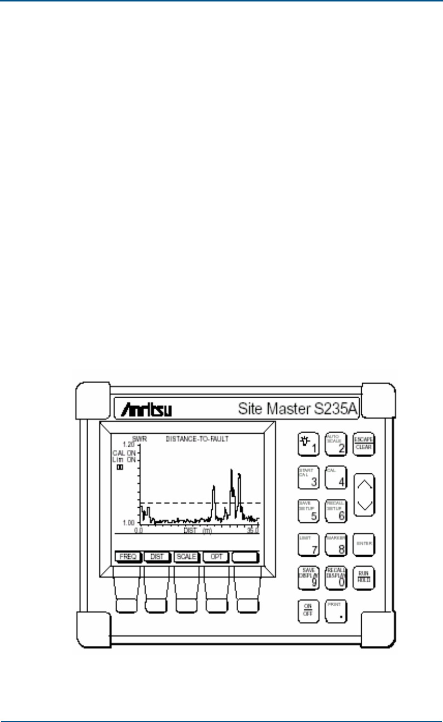
Appendix B - SiteMaster Usage
Confidential and Proprietary Information of ZTE CORPORATION 125
Measuring DTF
Take following steps to measure DTF:
1. Press <OPT>
2. Press <B1>and select {MODE}
3. Press <Up> or <Down> to choose [SWR] and press <Enter> for
confirmation.
4. Press <MAIN> to return to the main menu.
5. Input a proper frequency range if required.
6. Check meter if required.
7. Input a proper feeder length if required.
8. Press <MAIN> to return to the main menu.
9. Press <RUN> to take measurement.
10. Press <AUTO SCALE> to adjust screen Y-coordinates.
11. Press <Mark>to view SWR value of each frequency point within this
frequency band. Check the fault points. Figure 96 shows DTF
measurement.
12. Press <Save Display>to save data.
FIGURE 96 - MEASUREMENT OF ANTENNA FEEDER DTF

Confidential and Proprietary Information of ZTE CORPORATION 127
Acronyms
Abbreviation Full Name
1x EV 1x Evolution
1x EV - DO 1x Evolution Data Only
1x EV - DV 1x Evolution Data & Voice
2C3S Two carriers and three sectors
4C3S Four carriers and three sectors
A A Interface - Interface between BSC and MSC
AAA Authentication, Authorization and Accounting
Abis Abis Interface - Interface between BSC and BTS
ATM Asynchronous Transfer Mode
BDS Baseband Digital System
BIM BDS Interface Module
BSC Base Station Controller
BSS Base Station System
BTS Base Transceiver Station
CBTS O1 Compact Base Transceiver Station
CCM Communication Control Module
CDM Clock Distribution Module
CHM Channel Processing Module
DBS Database Subsystem
DSM Data Service Module
EPLD Electrically Programmable Logic Device
FA Foreign Agent
FER Frame Error Rate
FPGA Field Programmable Gate Arrays
GCM GPS Control Module
GCKM GPS Clock Module
HA Home Agent
HDLC High Level Data Link Control
HDR High Data Rate

ZXC10 CBTS O1 Hardware Installation Manual
128 Confidential and Proprietary Information of ZTE CORPORATION
Abbreviation Full Name
HLR Home Location Register
DPA High Power Amplifier
IP Internet Protocol
LNA Low Noise Amplifier
MAC Media Access Control
MBTS Master BTS
MSC Mobile Switching Center
MTBCF Mean Time Between Critical Failure
MTBF Mean Time Between Failure
MTTR Mean Time To Recovery
O&M Operations and Maintenance
OMC Operation and Maintenance Center
OSS Operating System Subsystem
OTD Orthogonal Transmit Diversity
OW Order Wire
PA Power Amplifier
PCF Packet Control Function
PDSN Packet Data Serving Node
PP2S Pulse Per 2 seconds
PPP Point to Point Protocol
RF Radio Frequency
RFS Radio Frequency Subsystem
RIM Radio Interface Module
RRFS Remote RFS
RSSI Received Signal Strength Indicator
RX Receiver
SAM Site Alarm Module
SBTS Slave BTS
SCH Synchronization Channel
SCS System Control Subsystem
SDH Synchronous Digital Hierarchy
SNM SDH Net Module
STS Space Time Spreading
TOD Time of Date
TX Transmit

Confidential and Proprietary Information of ZTE CORPORATION 129
Figures
Figure 1 - Hardware Installation Flow............................................................16
Figure 2 - Wooden Box ...............................................................................25
Figure 3 - Carton Box .................................................................................26
Figure 4 - Cabinet outer view.......................................................................30
Figure 5 - Cabinet Front View.......................................................................31
Figure 6 - Ground Installation Mode Flow.......................................................33
Figure 7 - Single Cabinet Concrete Platform (Units mm) ..................................34
Figure 8 - Channel Steel Cross Section (Units mm) .........................................34
Figure 9 - Drawing Lines for Single Cabinet Top View (Units mm)......................35
Figure 10 - Expansion Bolt Installation ..........................................................35
Figure 11 - Fixing Channel Steel...................................................................36
Figure 12 - Channel Steel Installation ...........................................................36
Figure 13 - Minimizing Error with Washer ......................................................37
Figure 14 - Fixing Cabinet ...........................................................................37
Figure 15 - Single Cabinet Installation...........................................................38
Figure 16 - Heat Exchanger Dismantling........................................................39
Figure 17 - Shutter Dismantling ...................................................................40
Figure 18 - Taking out Rectifier Module .........................................................41
Figure 19 - Rectifier Module – Handle in OPEN State .......................................41
Figure 20 - Windshield Cover Board Installation..............................................42
Figure 21 Completing Installation .................................................................43
Figure 22 - Power and Grounding Cable Connections .......................................47
Figure 23 - Cabinet Bottom Interface Top View...............................................48
Figure 24 - Cabinet Bottom Interface Bottom view ..........................................49
Figure 25 - Fiber Splice Tray........................................................................51
Figure 26 - E1 Cable Interface .....................................................................52
Figure 27 - 120 OHM E1 and 100 OHM T1 Interface ........................................52
Figure 28 - Power Supply and Grounding Cables.............................................53
Figure 29 - Cable Straps Requirements .........................................................54
Figure 30 - Cable Straps .............................................................................54
Figure 31 - 3-Sector Antenna Feeder System .................................................57
Figure 32 - Omni and Uni-Directional Antennas ..............................................58
Figure 33 - Super Flexible Jumper ................................................................58
Figure 34 - Main Feeder Cable......................................................................59
Figure 35 - Grounding Kit............................................................................59
Figure 36 - λ/4 Stub Lightning Arrester .........................................................60
Figure 37 - Graviton Lightning Arresters ........................................................60
Figure 38 - Connectors in Antenna Feeder System ..........................................61
Figure 39 - DIN Connectors .........................................................................61
Figure 40 - 7/16 Connectors ........................................................................62
Figure 41 - SMA Connectors ........................................................................62
Figure 42 - BNC Connector (M) ....................................................................62
Figure 43 - Antenna Installation Flow Chart ...................................................64
Figure 44 - Hoisting an Antenna ...................................................................65
Figure 45 - Kathrein Antenna Installation.......................................................66
Figure 46 - Antenna Fixing Support ..............................................................67
Figure 47 - U-Shaped Bolt ...........................................................................67
Figure 48 - Azimuth Adjusting Tool ...............................................................68
Figure 49 - Azimuth Gauge..........................................................................69
Figure 50 - Adjusting Tilt Angle ....................................................................69
Figure 51 - Adjusting Antenna Tilt ................................................................70

ZXC10 CBTS O1 Hardware Installation Manual
130 Confidential and Proprietary Information of ZTE CORPORATION
Figure 52 - Omni-Directional Antenna Installation ...........................................70
Figure 53 - CBTS O1 Main Feeder .................................................................71
Figure 54 - Connecting Jumper ....................................................................72
Figure 55 - Fixing Jumpers with Feeder Cable Clips .........................................72
Figure 56 - One Bend .................................................................................73
Figure 57 - Multiple Bend ............................................................................73
Figure 58 - Cable Hoisting Trawl...................................................................74
Figure 59 - Fixing Feeder Cable....................................................................74
Figure 60 - Lightning Arrester Installation......................................................76
Figure 61 - Sealing Lightning Arrester ...........................................................76
Figure 62 - Buckling Grip Ring .....................................................................77
Figure 63 - Winding Waterproof Adhesive Tape...............................................78
Figure 64 - Winding Electrically Insulated Adhesive Tape .................................78
Figure 65 - GPS Antenna Feeder System .......................................................82
Figure 66 - Tower Mounted GPS Antenna.......................................................83
Figure 67 - Roof Mounted GPS Antenna .........................................................84
Figure 68 - NJ-9 GPS Connector ...................................................................85
Figure 69 - NJ-9 GPS Connector Parts ...........................................................86
Figure 70 - Stripping GPS Cable ...................................................................86
Figure 71 - External Conductor Assembly ......................................................87
Figure 72 - Shielded Layer...........................................................................87
Figure 73 - Inserting External Conductor Flange .............................................87
Figure 74 - Stripping Insulation Layer ...........................................................88
Figure 75 - After Stripping Insulation Layer....................................................88
Figure 76 - Inserting Insulating Plate ............................................................89
Figure 77 - Welding Inner Conductor Pin .......................................................89
Figure 78 - Cutting Shielded Layer................................................................90
Figure 79 - Assembling Shell and Cable.........................................................90
Figure 80 - Shell Tightening.........................................................................91
Figure 81 - Board Installation Flow Chart.......................................................94
Figure 82 - CBTS O1 Board Slot ...................................................................95
Figure 83 - Board Plugging (Step 1)..............................................................96
Figure 84 - Board Plugging (Step 1)..............................................................97
Figure 85 - Board Plugging (Step 3)..............................................................97
Figure 86 - Wooden Packing Box for Cabinet ................................................ 112
Figure 87 - Wooden Packing Box for Parts....................................................113
Figure 88 - Cabinet Packing .......................................................................114
Figure 89 - Sealing a Box ..........................................................................114
Figure 90 - Inner Packing Foam Box ...........................................................115
Figure 91 - General Paper Packing Box for Boards......................................... 116
Figure 92 - Paper Packing Box for RFE Boards ..............................................116
Figure 93 - Packing RFE, DPA and TRX Board ............................................... 117
Figure 94 - Sealing and Packing ................................................................. 118
Figure 95 - Antenna Feeder SWR Test ......................................................... 123
Figure 96 - Measurement of Antenna Feeder DTF..........................................124

Confidential and Proprietary Information of ZTE CORPORATION 131
Tables
Table 1 - Typographical Conventions..............................................................xi
Table 2 - Mouse Operation Conventions......................................................... xii
Table 3 - Safety Signs ............................................................................... xiii
Table 4 - Installation Location Specifications ..................................................17
Table 5 - Temperature and Humidity Range ...................................................17
Table 6 - Power Supply Indices ....................................................................18
Table 7 - Power Consumption Requirements ..................................................18
Table 8 - Radiation Protection Requirements ..................................................19
Table 9 - Tool and Meter List .......................................................................20
Table 10 - Cabinet Weight ...........................................................................31
Table 11 - AC 220 V Interface......................................................................46
Table 12 - Cable Connection Relationship ......................................................50
Table 13 - Antenna Feeder Interfaces ...........................................................50

ZXC10 CBTS O1 Hardware Installation Manual
132 Confidential and Proprietary Information of ZTE CORPORATION
This page is intentionally blank

Confidential and Proprietary Information of ZTE CORPORATION 133
Index
4C3S .......................................125
AAA .........................................125
ABIS ........................................ 50
AC
18, 46, 47, 48, 49, 50, 51, 101,
108
ANT ...........................................50
ATM .........................................125
B 46, 50, 121
BDS ..............................93, 96, 125
BIM .........................................125
BS 19, 21
BSC ............ 19, 22, 50, 52, 108, 125
BSS ................................... 56, 125
BTS ....... 50, 72, 75, 76, 79, 125, 126
CBTS1, 3, 15, 16, 17, 18, 19, 22, 24,
25, 31, 32, 34, 46, 48, 50, 51, 52,
56, 58, 71, 93, 95, 99, 100, 101,
108, 109, 115, 118, 125
CCM .........................................125
CDMA2000 ................................ 1, 2
CHM .........................................125
DB25 ....................................... 113
DB44 .........................................52
DB9 ......................................... 113
DBS .........................................125
DC
18, 108
DSM .........................................125
DUP ......................................... 102
DV
125
E 1, 3, 27, 101, 122, 123, 124
E1 19, 48, 49, 50, 52, 53, 113
E1/T1...................................48, 52
EPLD .......................................125
ETSI .........................................19
EV
125
FA 125
FER .........................................125
FIBER........................................51
FPGA .......................................125
FREQ ....................................... 122
GCM .........................................125
GND .......................................... 50
GPS 48, 49, 50, 81, 82, 83, 84, 85, 86,
91, 99, 103, 104, 105, 118, 125
HA
125
HDLC .......................................125
HDR .........................................125
HLR .........................................126
INFORMATION ............................... 2
IP 126
LEGAL......................................... 2
LNA .........................................126
LOSS ....................................... 122
MAC .........................................126
MAIN ......................... 108, 123, 124
MASTER ................................ 21, 79
MODE ................................ 123, 124
MS
21, 50
MSC ................................. 125, 126
MTBCF......................................126
MTBF .......................................126
MTTR .......................................126
N/A ............................................ 3
N-F .......................................... 50
O&M .........................................126
OFF ......................................... 108
OHM .......................................... 52
OMC .........................................126
OPEN ....................................... 122
OSS .........................................126
OTD .........................................126
OW 126
P 1, 3, 126
PA 115, 126
PCF .........................................126
PDSN .......................................126
PGND ....................................... 101
PP2S .......................................126
PPM ......................................... 115
PPP .........................................126
R&D ............................................ 3
R1
2
RF 48, 50, 61, 62, 75, 76, 79, 99, 102,
103, 105, 126
RFE .. 50, 95, 112, 115, 116, 117, 123
RFE-DIV .................................. 115
RFE-DUP .................................. 115
RFS ..............................93, 96, 126
RIM .........................................126
RSSI .......................................126
RX
50, 126
SAM .........................................126
SCALE............................... 123, 124
SCH .........................................126
SCS .........................................126
SDH .........................................126

ZXC10 CBTS O1 Hardware Installation Manual
134 Confidential and Proprietary Information of ZTE CORPORATION
SHORT...................................... 122
SITE ................................... 21, 79
SMA ...........................................62
SNM .........................................126
STS .........................................126
SWR ........ 99, 103, 105, 121, 123, 124
TOD .........................................126
TRX ............... 95, 102, 112, 115, 117
TX
50, 79, 126
URL ............................................ 1
V 18, 46, 80, 101, 108, 122
VSWR ............................ 20, 79, 105
ZXC10..........1, 3, xi, 16, 18, 22, 46