ZTE R8872AS1900 Macro Radio Remote Unit User Manual ZXSDR R8872A Product Description
ZTE Corporation Macro Radio Remote Unit ZXSDR R8872A Product Description
ZTE >
Users Manual

ZXSDR R8872A Product Description
UniRAN 16/GUL Multi-Mode

ZXSDR R8872A Product Description
ZTE Confidential & Proprietary 1
ZXSDR R8872A Product Description
Version
Date
Author
Reviewer
Notes
V1.00
2017/01/26
Yang Lisha
1. Update static receiver sensitivity
2. Update Reliability
3. Update power consumption
4. Update 256QAM in downlink
V1.10
2017/03/16
Yu Yang
1. Update capacity
2. Update bandwidth
© 2017 ZTE Corporation. All rights reserved.
ZTE CONFIDENTIAL: This document contains proprietary information of ZTE and is not to be disclosed or used
without the prior written permission of ZTE.
Due to update and improvement of ZTE products and technologies, information in this document is subjected to
change without notice.

ZXSDR R8872A Product Description
2 ZTE Confidential & Proprietary
TABLE OF CONTENTS
1 Overview ............................................................................................................ 4
1.1 Introduction .......................................................................................................... 4
1.2 Benefits ................................................................................................................ 4
1.3 Application Scenarios .......................................................................................... 5
2 Product Architectures ....................................................................................... 6
2.1 Physical Appearance ........................................................................................... 6
2.2 Hardware Architecture ......................................................................................... 6
2.2.1 QTR ..................................................................................................................... 7
2.2.2 DFL ...................................................................................................................... 8
2.2.3 PA 8
2.2.4 PWR .................................................................................................................... 9
2.2.5 PIB ....................................................................................................................... 9
2.3 Software Architecture ........................................................................................... 9
2.4 Functionality ....................................................................................................... 10
3 Technical Specifications ................................................................................. 11
3.1 Physical Indices ................................................................................................. 11
3.2 Performance Indices .......................................................................................... 12
3.2.1 Operation Frequency Band ................................................................................ 12
3.2.2 Capacity ............................................................................................................. 12
3.2.3 ToC Output Power ............................................................................................. 13
3.2.4 Bandwidth .......................................................................................................... 13
3.2.5 Receiver Sensitivity ............................................................................................ 14
3.3 Power Indices .................................................................................................... 14
3.3.1 Power Requirements ......................................................................................... 14
3.3.2 Power Consumption ........................................................................................... 14
3.4 Interface Indices ................................................................................................ 15
3.5 Transmission ..................................................................................................... 17
3.6 Working Environment Indices............................................................................. 18
3.7 Electromagnetic Compatibility Indices ................................................................ 18
3.8 Reliability Indices ............................................................................................... 18
4 Glossary ........................................................................................................... 20

ZXSDR R8872A Product Description
ZTE Confidential & Proprietary 3
FIGURES
Figure 1-1 Application Scenarios ........................................................................................ 5
Figure 2-1 Physical Appearance ......................................................................................... 6
Figure 2-2 System Structure ............................................................................................... 7
Figure 2-3 R8872A Software Architecture ..........................................................................10
Figure 3-1 Physical Appearance ........................................................................................11
Figure 3-2 External Interfaces at the Bottom ......................................................................15
Figure 3-3 External Interfaces on the Right Side ................................................................16
Figure 3-4 LED Indicators on the Panel .............................................................................17
TABLES
Table 3-1 Physical Indices .................................................................................................12
Table 3-2 Operation Frequency Band ................................................................................12
Table 3-3 Capacity .............................................................................................................13
Table 3-4 ToC Output Power .............................................................................................13
Table 3-5 Static Receiver Sensitivity ..................................................................................14
Table 3-6 Power Supply .....................................................................................................14
Table 3-7 Power Consumption ...........................................................................................15
Table 3-8 Description of the External Interfaces at the Bottom ...........................................16
Table 3-9 Description of the External Interfaces on the Right Side .....................................17
Table 3-10 CPRI Interfaces ................................................................................................18
Table 3-11 Environment Indices.........................................................................................18
Table 3-12 Electromagnetic Compatibility Indices ..............................................................18
Table 3-13 Reliability Characteristics .................................................................................19

ZXSDR R8872A Product Description
4 ZTE Confidential & Proprietary
1 Overview
1.1 Introduction
This document provides a high level description of ZTE ZXSDR R8872A (hereinafter
referred to as R8872A), which is the latest compact RRU (Remote Radio Unit) used in
ZTE wireless communication solution. Based on ZTE common innovative SDR platform,
R8872A can work in GSM, UMTS, or LTE single mode or multi-mode at the same
frequency band. The volume of R8872A is 20L, and its weight is 23Kg.
The document is designed to give an overview of the characteristics of R8872A, its key
benefits, the architecture, functionality and services. The document also describes the
system capabilities.
1.2 Benefits
High performance
R8872A has 2*80W of high TOC output power. With high output power, it supports
large capacity which can be used in large site in dense urban with high traffic.
R8872A is designed with wide bandwidth to meet with the growing demands for
wide working bandwidth. E.g., R8872A supports 75MHz of IBW (instantaneous
bandwidth) in band3 1800MHz frequency band. RRUs with full working bandwidth
integrate more spectrum resources and help to decrease hardware investment
exponentially.
SDR 2T4R design to ensure one clear and simple network
R8872A supports GSM, UMTS, LTE or mixed technologies. Design of 2T4R
channels ensures the smooth evolution of the system from GSM/UMTS to LTE 2*2
MIMO. Instead of running hardware on independent platforms for each technology,
operators can implement various wireless technologies through software
configuration on the same hardware platform. It fully satisfies operators’
ZXSDR R8872A Product Description
ZTE Confidential & Proprietary 5
requirements of hybrid network deployment and long term evolution with lowest
cost.
Lower Total Cost of Ownership (TCO)
ZXSDR R8872A’s PA adopts advanced efficiency enhancement technologies to
realize high power efficiency, such as Doherty PA, DPD linear technology and
MCPA technology. It also supports dynamic adaptive PA power supply due to the
output power. Power consumption can be greatly decreased together with these
features.
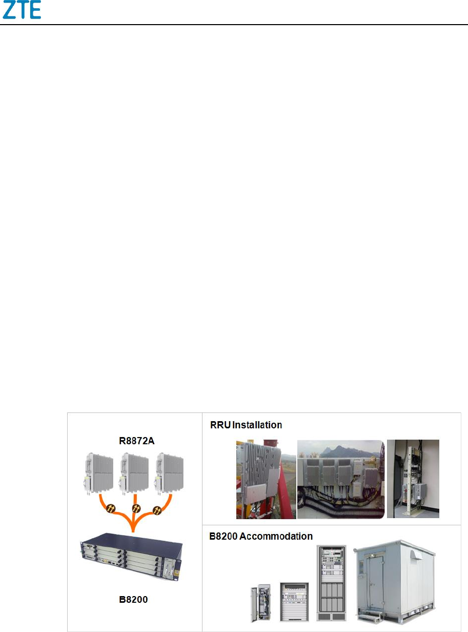
1.3 Application Scenarios
R8872A as the Remote Radio Unit and Baseband Unit (BBU) comprise distributed macro
base station BS8700. It can be used in dense urban area with high traffic. Typical
application scenarios of R8872A are shown in the following figure:
Figure 1-1 Application Scenarios
ZXSDR R8872A Product Description
6 ZTE Confidential & Proprietary
2 Product Architectures
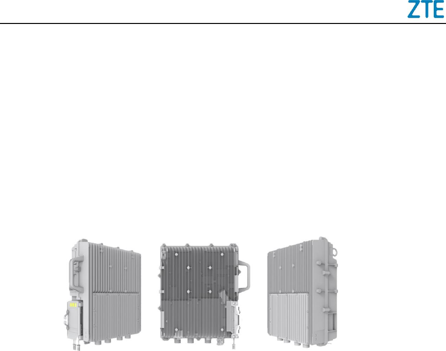
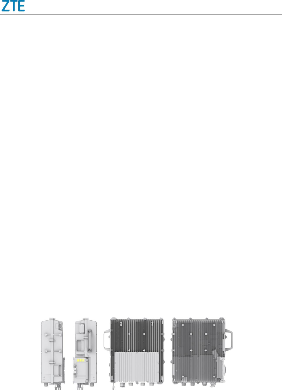
2.1 Physical Appearance
The physical appearances of R8872A are shown in the following figure.
Figure 2-1 Physical Appearance
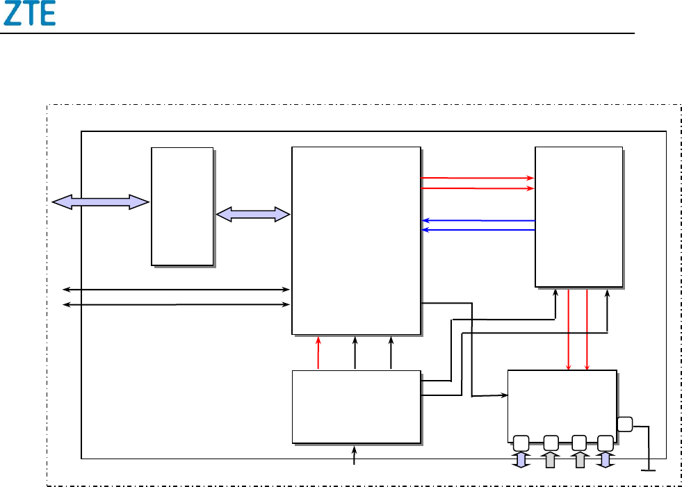
2.2 Hardware Architecture
The hardware architecture of R8872A is shown in Figure 2-2.
ZXSDR R8872A Product Description
ZTE Confidential & Proprietary 7
Figure 2-2 System Structure
R8872A includes 5 main hardware modules:
Quad-channel Transceiver (QTR)
Duplex Filters LNA (DFL)
2x Power Amplifier (PA)
Power module (PWR)
Protecting Interface Board (PIB)
2.2.1 QTR
The QTR has following functions:
Process 4 received signals and 2 transmitted signals;
Convert uplink and downlink radio signal;
Multiplex downlink IQ signal and de-multiplex uplink signal;
PIB
QTR
PWR
DFL
CPRI 1
CPRI 2
PWR ALM
P
A
O
u
t
DC in
ANT1 ANT2 ANT3 ANT4
R8872A
2 x PA
PA Out
GND
CPRI links
AISG/MON

ZXSDR R8872A Product Description
8 ZTE Confidential & Proprietary
Amplify, filter and convert A/D and D/A signal;
Convert between optical and electric signal;
Capture reference clock signal from baseband unit and provide clock signal to other
units;
Measure and report voltage standing wave ratio (VSWR);
Self-detect and report hardware failure alarm;
Detect and report over-heat alarm;
Provide communication interfaces, including,
Two CPRI interfaces
one DB15 port, for 2 dry contacts, one local debugging or AISG connection
through different kind of cables
Reset function.
2.2.2 DFL
The DFL has following functions:
Combine and isolate transmitted and received signals;
Filter the transmitted signal and received signal;
Provide DFL alarm monitor function.
2.2.3 PA
The PA has following functions:
Perform radio signal amplifying function;
Implement temperature report function;
Implement Low-Noise-Amplifier (LNA) function;

ZXSDR R8872A Product Description
ZTE Confidential & Proprietary 9
Implement over-current, over-heat, over-power and over-standing wave protecting
function.
2.2.4 PWR
The PWR has following functions:
Provide power supply function;
Monitor input over-voltage/under-voltage, input power outage, output over-voltage/
under-voltage, output over-current alarm, and report it to QTR board.
2.2.5 PIB
The PIB has the following function:
Integrate lightning protection unit for DB15 interface, and the protection level is 20
KA.
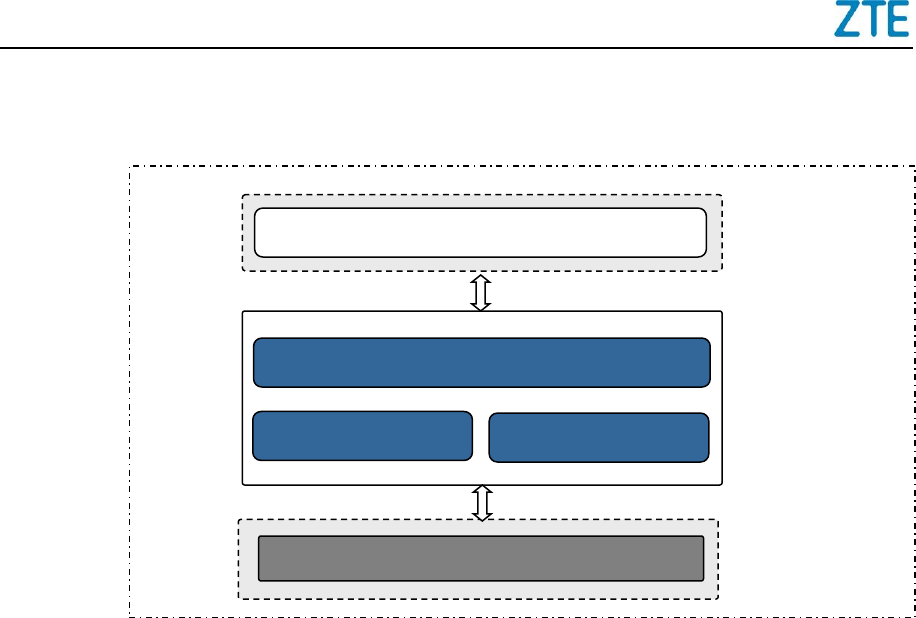
2.3 Software Architecture
The software architecture of R8872A can be divided into two layers, SDR Unified
Platform Software and Application Software. The architecture is shown in the following
figure:
ZXSDR R8872A Product Description
10 ZTE Confidential & Proprietary
Figure 2-3 R8872A Software Architecture
The Operating and Maintenance (OAM) sub-system is the application layer. Its main
functions are software downloading, configuration, management, system maintenance
and measurement.
The Operation Support Sub-system (OSS) is the supporting layer in this entire
framework. It is a hardware independent layer that provides basic functions such as
scheduling, timer, and memory management, communication, sequencing control,
monitoring, alarming and logging.
The Board Support Package (BSP) provides device driver & initialization and supports
basic functions like alarming and monitoring. It also provides the related interfaces and
services to the Operating System.
2.4 Functionality
R8872A is the remote radio unit of distributed base station. The signal is transmitted/
received through R8872A to/from base band processing unit for further processing via
standard CPRI interface.
By applying the distributed system, the feeder loss will be eliminated when the radio unit
is positioned close to the antenna. The coverage is enlarged with this solution.
Hardware
BSP
OSS
Linux
OAM
SDR Unified
Platform
Software
Application
Software
Hardware
System
ZXSDR R8872A Product Description
ZTE Confidential & Proprietary 11
The functions of R8872A include:
Support LTE bandwidth defined in 3GPP
Support 850/900/1800/1900 MHz frequency band
Support 2T4R in one box which can optimize spectrum efficiency greatly and
improve network uplink performance
Support 256QAM modulation in LTE downlink and 64QAM in uplink
Support transmit power report function for every carrier
Support overload protection function for power amplifier
Support transmit channel switching on/off function.
3 Technical Specifications
3.1 Physical Indices
R8872A is the multi-carrier RRU with two transmitters. The physical appearance is
shown below.
Figure 3-1 Physical Appearance

ZXSDR R8872A Product Description
12 ZTE Confidential & Proprietary
Table 3-1 Physical Indices
Item
Indices
Size (H*W*D) (mm)
415*352*137 mm (20L)
Weight (kg)
23 kg
Color
Silver gray
3.2 Performance Indices
3.2.1 Operation Frequency Band
Table 3-2 Operation Frequency Band
RRU Type
Band
Operation Radio
Frequency Band
Mode
R8872A S8500
B5, 850 MHz
Tx: 869 – 894 MHz
Rx: 824 – 849 MHz
GUL multi-mode
R8872A S9000
B8, 900 MHz
Tx: 934 – 960 MHz
Rx: 889 – 915 MHz
GL dual-mode
R8872A S1800
B3, 1800 MHz
TX: 1805 – 1880 MHz
RX: 1710 – 1785 MHz
GL dual-mode
R8872A S1900
B2, 1900 MHz
Tx: 1930 – 1990 MHz
Rx: 1850 – 1910 MHz
GUL multi-mode
3.2.2 Capacity

ZXSDR R8872A Product Description
ZTE Confidential & Proprietary 13
Table 3-3 Capacity
RRU Type
System
RRU Capacity
R8872A S8500
R8872A S1900
GSM single mode
2*4 TRXs
UMTS single mode
2*2 CSs
LTE single mode
L 2*20M 2T2R Cells
L 1*20M 2T2R Cell + L 1*15M 2T2R Cell
GUL multi-mode
G 2*2TRXs + U 2*1CSs + L 1*10M 2T2R Cell
R8872A S9000
GSM single mode
2*6 TRXs
LTE single mode
2*10MHz 2T2R/2T4R Cells
GL dual-mode
G 2*4TRXs+L 1*10MHz 2T2R/2T4R Cell, or
G 2*2TRXs+L 2*10MHz 2T2R/2T4R Cells
R8872A S1800
GSM single mode
2*6 TRXs
LTE single mode
2*20MHz 2T2R/2T4R Cells
GL dual-mode
G 2*4TRXs+L 1*20MHz 2T2R/2T4R Cell, or
G 2*2TRXs+L 2*20MHz 2T2R/2T4R Cells
3.2.3 ToC Output Power
Table 3-4 ToC Output Power
RRU Type
TOC Output Power[1]
R8872A
2*80W
Note: When “ZGO-04-01-011 Power Boost for 8PSK” is applied in GSM mode, the TOC output
power achieves the same in 8PSK modulation as in GMSK.
3.2.4 Bandwidth
R8872A supports all LTE bandwidth defined in 3GPP 15/20 MHz.
1
The TOC here means the max capability of the hardware. The specific TOC output power is limited by the
license.

ZXSDR R8872A Product Description
14 ZTE Confidential & Proprietary
3.2.5 Receiver Sensitivity
The receiver sensitivity of R8872A is shown as following table.
Table 3-5 Static Receiver Sensitivity
Mode
Frequency
Spectrum (MHz)
Single
Antenna
(dBm)
Dual Antennas
(dBm)
Four Antennas
(dBm)
GSM
850/900/1800/1900
-113.5
-116
-
UMTS
850/1900
-126.4
-129.1
-
LTE
900/1800
-106.4
-109.2
-112
850/1900
-106.4
-109.2
N/A
3.3 Power Indices
3.3.1 Power Requirements
The following table describes the power supply and the fluctuation range.
Table 3-6 Power Supply
Item
Index
Power Supply
DC: -48 V (-37 V – -60 V DC)
R8872A supports integrated lightning protection module for DC power supply. Its
protection level is 20 KA.
3.3.2 Power Consumption
Power consumptions of R8872A at normal ambient temperature are shown in the table
below:
ZXSDR R8872A Product Description
ZTE Confidential & Proprietary 15
Table 3-7 Power Consumption
RRU Type
Configuration
Typical Power
Consumption
Peak Power
Consumption
R8872A S1800
GSM S8*20W
275W
555W
GSM S2*2*20W+LTE 2*40W
335W
555W
R8872A S9000
GSM S8*20W
295W
575W
LTE S2, 2*40W/LTE cell
315W
575W
GSM S2*2*20W+LTE 2*40W
355W
575W
R8872A S8500
LTE 2*80W
315W
600W
R8872A S1900
LTE 2*80W
290W
550W
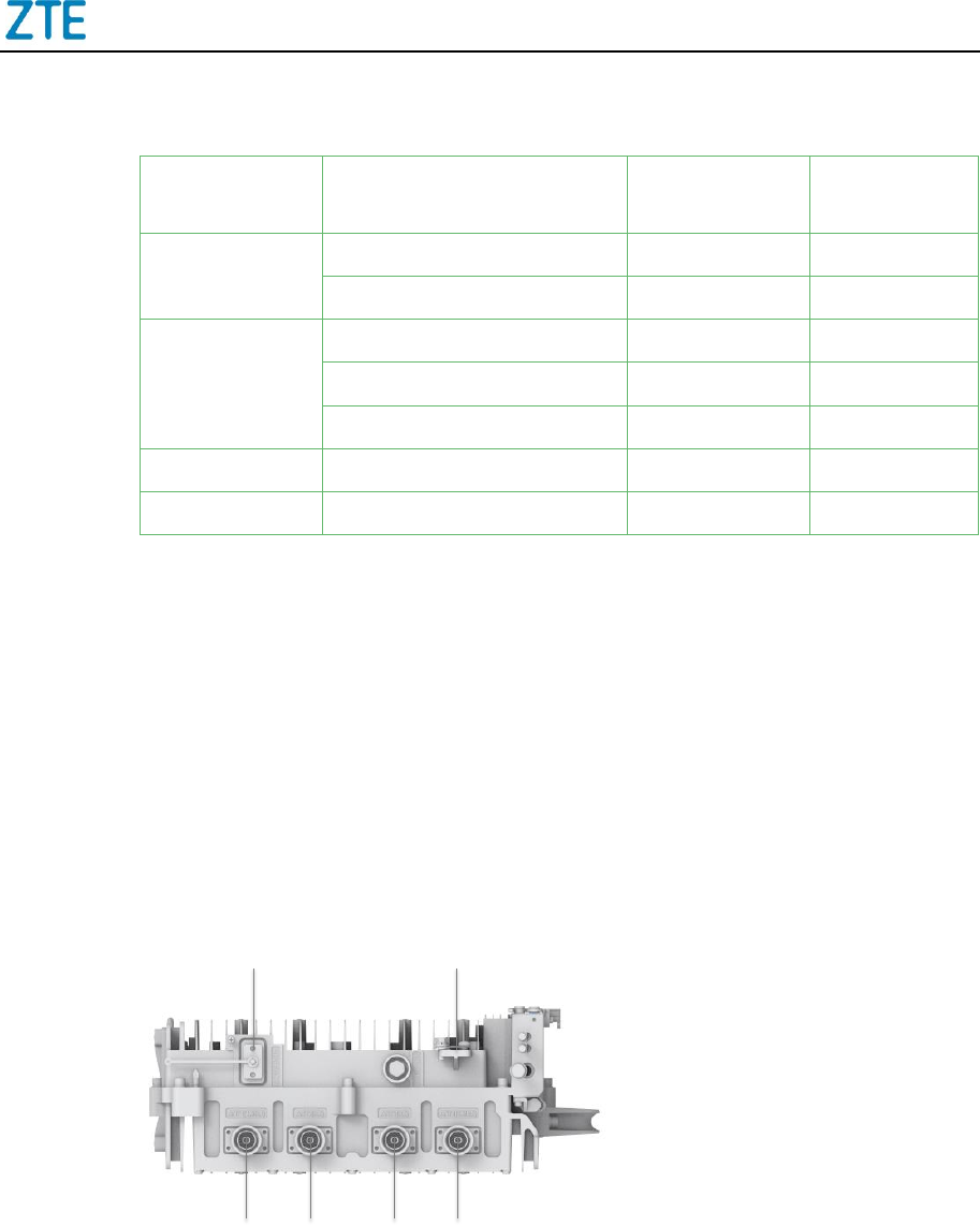
3.4 Interface Indices
The external interfaces of the R8872A are located at the bottom and on the front side of
the chassis.
Figure 3-2 shows the external interfaces at the bottom of the R8872A chassis.
Figure 3-2 External Interfaces at the Bottom
For a description of the external interfaces at the bottom of the R8872A chassis, refer to
the following table.
1 2
3 4 5 6
ZXSDR R8872A Product Description
16 ZTE Confidential & Proprietary
Table 3-8 Description of the External Interfaces at the Bottom
No.
Label
Interface
Interface Type/Connector
1
AISG/MON
AISG equipment interface
MON external monitoring
interface
LMT O&M Ethernet interface
DB15 connector
2
GND
Protective grounding interface
16 mm2 yellow-green round
terminal
3
ANT1
(TX/RX)
TX/RX antenna interface
50 Ω DIN-mode connector
4
ANT2 (RX)
RX antenna interface
50 Ω DIN-mode connector
5
ANT3 (RX)
RX antenna interface
50 Ω DIN-mode connector
6
ANT4
(TX/RX)
TX/RX antenna interface
50 Ω DIN-mode connector
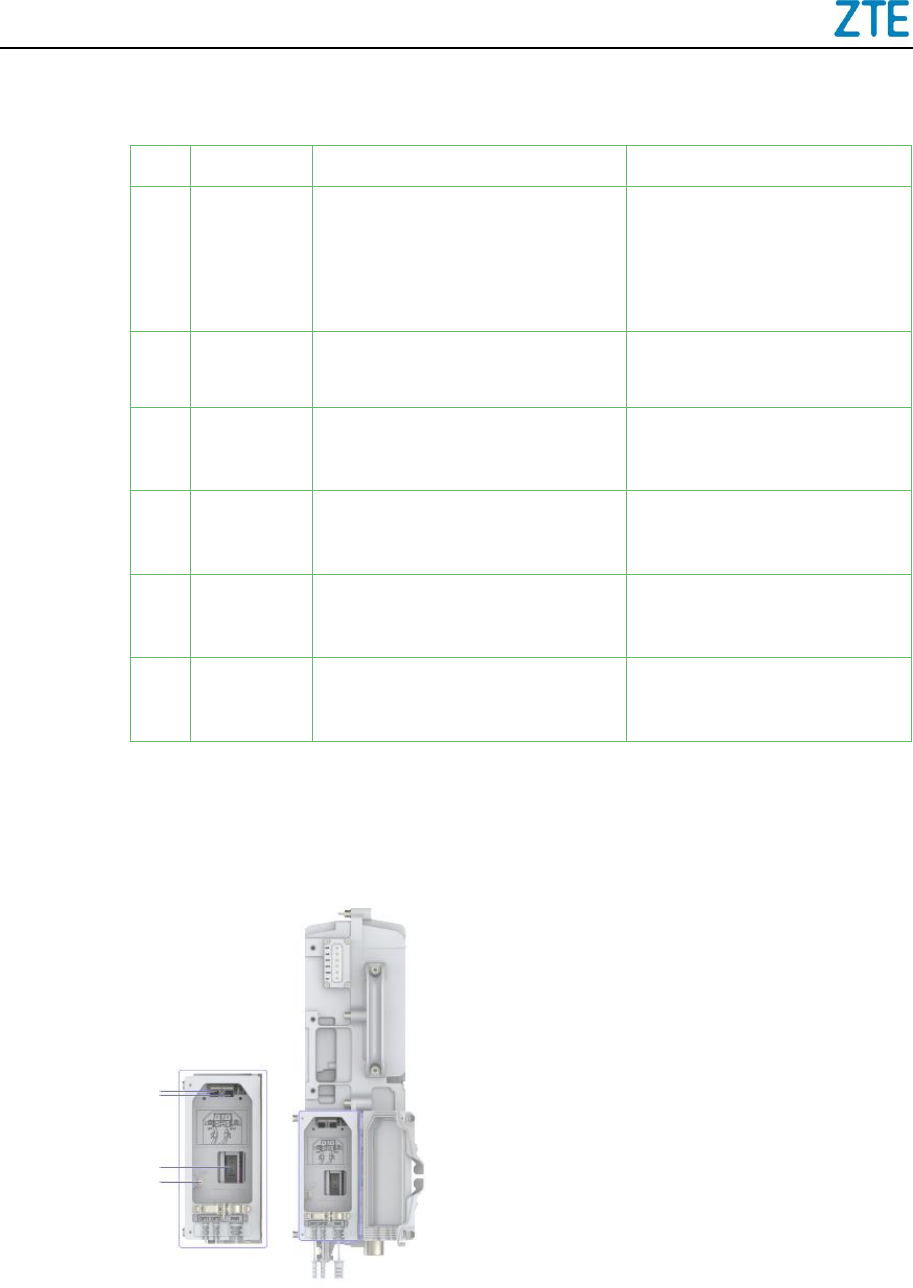
Figure 3-3 shows the external interfaces on the right side of the R8872A chassis.
Figure 3-3 External Interfaces on the Right Side
For a description of the external interfaces on the right side of the R8872A chassis, refer
to the following table.
1
2
3
4
ZXSDR R8872A Product Description
ZTE Confidential & Proprietary 17
Table 3-9 Description of the External Interfaces on the Right Side
No.
Label
Interface
Interface Type/Connector
1
OPT1
Interface for communication
between the RRU and a BBU,
or RRU cascading interface
LC-type optical interface (IEC
874)
2
OPT2
RRU cascading interface
LC-type optical interface (IEC
874)
3
PWR
Power input interface
2-pin customized connector
4
Grounding cable interface for
AC power supply
-
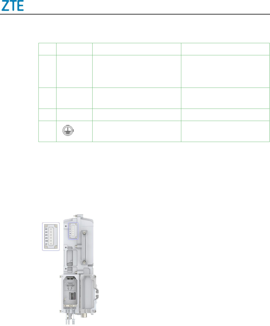
Additionally, R8872A provides 6 LED indicators. The indicators on the R8872A panel
indicate the operating status of the RRU. The indicators are located on the front side of
the chassis, see Figure 3-4.
Figure 3-4 LED Indicators on the Panel
3.5 Transmission
R8872A is connected to BBU through CPRI interfaces.
For more information about CPRI interfaces, refer to the following table.

ZXSDR R8872A Product Description
18 ZTE Confidential & Proprietary
Table 3-10 CPRI Interfaces
Item
Value
Interface Type
Speed
Standard
CPRI interface
2
SFP (LC)
6.144 Gbps [2]
CPRI V4.2
3.6 Working Environment Indices
Table 3-11 Environment Indices
Item
Characteristics
Temperature
-40 to +55 °C
Relative Humidity
5% to 100%
Waterproof/Dustproof
IP65
Ground
≤5 Ω; earth resistance can be less than 10 Ω in
thunder-less area where thunderstorm days is less
than 20 per year.
3.7 Electromagnetic Compatibility Indices
Table 3-12 Electromagnetic Compatibility Indices
Item
Characteristics
Static Discharge Immunity
Contact Discharge: ±6000V
Air Discharge: ±8000V
Surge Impact Immunity
DC Power port Line(Ground): ±2000V
3.8 Reliability Indices
2
The speed here refers to the max capability of the hardware. The specific speed depends on the optical module
configuration.

ZXSDR R8872A Product Description
ZTE Confidential & Proprietary 19
Table 3-13 Reliability Characteristics
Item
R8872A
MTBF
DC: ≥458,000 hours
MTTR
1 hour
Availability index
DC: ≥99.999782%
Down duration
DC: ≤1.148 min/year

ZXSDR R8872A Product Description
20 ZTE Confidential & Proprietary
4 Glossary
Abbreviations
Full Name
BBU
Base Band processing Unit
BSP
Board Support Package
CPRI
Common Public Radio Interface
DL
Downlink
DFL
Duplexer & Filters
DPD
Digital Pre-Distortion
GSM
Global System for Mobile communications
LMT
Local Maintenance Terminal
LNA
Low-Noise-Amplifier
LTE
Long Term Evolution
MCPA
Multi-Carrier Power Amplifier
MIMO
Multi Input Multi Output
MTBF
Mean Time Between Failures
MTTR
Mean Time To Recovery
OAM
Operating And Maintenance
OSS
Operation Support Sub-system
PA
Power Amplifier
PWR
Power
QTR
Quad-channel Transceiver
RF
Radio Frequency
RRU
Remote Radio Unit
SDR
Software Defined Radio
ToC
Top of Cabinet
UE
User Equipment
UL
Uplink
VSWR
Voltage Standing Wave Ratio