ZTE R8882L268 ZXSDR R8882 L268 is base station, which is supporting FDD LTE band 7 User Manual ZXSDR R8882 L268
ZTE Corporation ZXSDR R8882 L268 is base station, which is supporting FDD LTE band 7 ZXSDR R8882 L268
ZTE >
User Manual-ZXSDR R8882 L268

ZXSDRR8882L268
LTERemoteRadioFrequencyUnit
UserManual
Version:V2.00
ZTECORPORATION
No.55,Hi-techRoadSouth,ShenZhen,P .R.China
Postcode:518057
Tel:+86-755-26771900
Fax:+86-755-26770801
URL:http://ensupport.zte.com.cn
E-mail:support@zte.com.cn

LEGALINFORMATION
Copyright©2013ZTECORPORATION.
Thecontentsofthisdocumentareprotectedbycopyrightlawsandinternationaltreaties.Anyreproductionor
distributionofthisdocumentoranyportionofthisdocument,inanyformbyanymeans,withoutthepriorwritten
consentofZTECORPORATIONisprohibited.Additionally,thecontentsofthisdocumentareprotectedby
contractualcondentialityobligations.
Allcompany,brandandproductnamesaretradeorservicemarks,orregisteredtradeorservicemarks,ofZTE
CORPORATIONoroftheirrespectiveowners.
Thisdocumentisprovided“asis”,andallexpress,implied,orstatutorywarranties,representationsorconditions
aredisclaimed,includingwithoutlimitationanyimpliedwarrantyofmerchantability,tnessforaparticularpurpose,
titleornon-infringement.ZTECORPORATIONanditslicensorsshallnotbeliablefordamagesresultingfromthe
useoforrelianceontheinformationcontainedherein.
ZTECORPORATIONoritslicensorsmayhavecurrentorpendingintellectualpropertyrightsorapplications
coveringthesubjectmatterofthisdocument.ExceptasexpresslyprovidedinanywrittenlicensebetweenZTE
CORPORATIONanditslicensee,theuserofthisdocumentshallnotacquireanylicensetothesubjectmatter
herein.
ZTECORPORATIONreservestherighttoupgradeormaketechnicalchangetothisproductwithoutfurthernotice.
UsersmayvisitZTEtechnicalsupportwebsitehttp://ensupport.zte.com.cntoinquirerelatedinformation.
TheultimaterighttointerpretthisproductresidesinZTECORPORATION.
RevisionHistory
RevisionNo.RevisionDateRevisionReason
R1.02011–01–19FirstEdition
SerialNumber:SJ-20110104194923-001
PublishingDate:2011-01-19(R1.0)
SJ-20110104194923-001|2011-01-19(R1.0)ZTEProprietaryandCondential

Contents
AboutThisManual.........................................................................................I
Chapter1FCCStatement..........................................................................1-1
Chapter2ProductOverview.....................................................................2-1
2.1DistributedeNodeBSolution...............................................................................2-1
2.2ProductPositioninNetwork................................................................................2-3
2.3ProductFeatures................................................................................................2-4
2.4ProductFunctions..............................................................................................2-4
2.5ProductAppearance...........................................................................................2-5
2.6InstallationScenario...........................................................................................2-5
2.7ProductNetworking............................................................................................2-5
2.8OperationandMaintenanceIntroduction..............................................................2-6
2.9ProductExternalInterfaces.................................................................................2-7
2.10ProductIndicators............................................................................................2-9
Chapter3ProuductTechnicalIndices.....................................................3-1
3.1PhysicalIndices.................................................................................................3-1
3.2WorkingEnvironment.........................................................................................3-1
3.3Bandwidth..........................................................................................................3-1
3.4PowerRequirements..........................................................................................3-2
3.5PowerConsumption...........................................................................................3-2
3.6TransmissionIndex............................................................................................3-2
3.7PerformanceIndices...........................................................................................3-2
3.8ElectromagneticCompatibility.............................................................................3-3
3.9Reliability...........................................................................................................3-6
Chapter4ProductInstallation..................................................................4-1
4.1SafetyDescription.............................................................................................4-1
4.1.1SafetyGuide............................................................................................4-1
4.1.2SymbolDescription..................................................................................4-1
4.1.3SafetyInstructions....................................................................................4-3
4.1.4HoistingOperationInstructions..................................................................4-5
4.2PreparationBeforeInstallation............................................................................4-6
4.2.1PersonnelPreparation..............................................................................4-6
4.2.2ContainerofZXSDRR8882L268..............................................................4-6
4.2.3UnpackingandCheckingFlow..................................................................4-7
I
SJ-20110104194923-001|2011-01-19(R1.0)ZTEProprietaryandCondential

4.2.4InstallationAccessories............................................................................4-8
4.2.5InstallationFlow.......................................................................................4-9
4.3MountingOnWall.............................................................................................4-10
4.4MountingOnPole............................................................................................4-14
4.4.1One-T o-OneMounting............................................................................4-14
4.4.2One-T o-TwoMounting............................................................................4-16
4.4.3One-T o-ThreeMounting..........................................................................4-18
4.5MountingOnGantry.........................................................................................4-21
4.6ConnectingCables...........................................................................................4-25
4.6.1ConnectionofExternalCables................................................................4-25
4.6.2ExternalCableInstallationFlow..............................................................4-26
4.6.3InstallingPowerCable............................................................................4-27
4.6.4InstallingGroundingCable......................................................................4-29
4.6.5InstallingFiberBetweeneBBUandeRRU...............................................4-29
4.6.6InstallingFibersBetweeneRRUs............................................................4-31
4.6.7InstallingEnvironmentMonitorCable.......................................................4-32
4.6.8InstallingAISGControlCable..................................................................4-33
4.6.9InstallingAntennaFeederJumper...........................................................4-34
Figures.............................................................................................................I
Tables............................................................................................................III
Glossary.........................................................................................................V
II
SJ-20110104194923-001|2011-01-19(R1.0)ZTEProprietaryandCondential
AboutThisManual
Purpose
Thismanualgivesintroductionontheproductdescription,technicalindices,andproduct
installation.
IntendedAudience
lHardwareInstallationEngineer
lOperationandMaintenanceEngineer
PrerequisiteSkillandKnowledge
Tousethisdocumenteffectively,usersshouldhaveageneralunderstandingofwireless
telecommunicationstechnology.FamiliaritywithLTEwirelessnetworkanditsrelated
componentsishelpful.
WhatisinThisManual
ChapterSummary
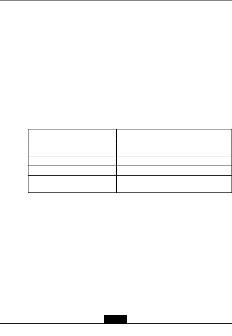
Chapter1,FCCStatementIntroducestheFCCstatementsthatthisdevicecomplies
with
Chapter2,ProductOverviewDescribesproductcharacteristic,interfaces,indicators
Chapter3,ProductT echnicalIndicesDescribesthetechnicalindicesoftheproduct
Chapter4,ProductInstallationDescribesinstallationandcableconnectionofthe
product
I
SJ-20110104194923-001|2011-01-19(R1.0)ZTEProprietaryandCondential

II
SJ-20110104194923-001|2011-01-19(R1.0)ZTEProprietaryandCondential
Chapter1
FCCStatement
FCC&ICStatement
ThisdevicecomplieswithPart15oftheFCCRules.Operationissubjecttothefollowing
twoconditions:
lThisdevicemaynotcauseharmfulinterference.
lThisdevicemustacceptanyinterferencereceived,includinginterferencethatmay
causeundesiredoperation.
Note:
ThisequipmenthasbeentestedandfoundtocomplywiththelimitsforaClassAdigital
device,pursuanttoPart15oftheFCCRules.Theselimitsaredesignedtoprovide
reasonableprotectionagainstharmfulinterferencewhentheequipmentisoperatedin
acommercialenvironment.Thisequipmentgenerates,uses,andcanradiateradio
frequencyenergyand,ifnotinstalledandusedinaccordancewiththeinstructionmanual,
maycauseharmfulinterferencetoradiocommunications.
Operationofthisequipmentinaresidentialareaislikelytocauseharmfulinterferencein
whichcasetheuserwillberequiredtocorrecttheinterferenceathisownexpense.
Caution!
Changesormodicationstothisunitnotexpresslyapprovedbythepartyresponsiblefor
compliancewillvoidtheuser’sauthoritytooperatetheequipment.Anychangetothe
equipmentwillvoidFCCandICgrant.
FCCRadiationExposureStatement
ThisequipmentcomplieswithFCCradiationexposurelimitssetforthforanuncontrolled
environment.Thisequipmentshouldbeinstalledandoperatedwithminimumdistance4
mbetweentheradiator&yourbody.
1-1
SJ-20110104194923-001|2011-01-19(R1.0)ZTEProprietaryandCondential

ZXSDRR8882L268UserManual
Thispageintentionallyleftblank.
1-2
SJ-20110104194923-001|2011-01-19(R1.0)ZTEProprietaryandCondential

Chapter2
ProductOverview
TableofContents
DistributedeNodeBSolution.......................................................................................2-1
ProductPositioninNetwork........................................................................................2-3
ProductFeatures........................................................................................................2-4
ProductFunctions......................................................................................................2-4
ProductAppearance...................................................................................................2-5
InstallationScenario...................................................................................................2-5
ProductNetworking....................................................................................................2-5
OperationandMaintenanceIntroduction....................................................................2-6
ProductExternalInterfaces........................................................................................2-7
ProductIndicators......................................................................................................2-9
2.1DistributedeNodeBSolution
Tosupplycustomerswithmorecompetitivecommunicationequipmentandsolutioninthe
market,ZTEdevelopsandpromotesZTESDReBBU(basebandunit)andeRRU(remote
radiounit)distributedeNodeBsolutiontimely,whichjointlyperformLTEeNodeBservice.
ZTEdistributedeNodeBsolutionisshowninFigure2-1.
2-1
SJ-20110104194923-001|2011-01-19(R1.0)ZTEProprietaryandCondential
ZXSDRR8882L268UserManual
Figure2-1ZTEDistributedeNodeBSolution
ZTE'sLTEeBBU+eRRUdistributedeNodeBsolutionhasthefollowingpredominance:
1.Savinglaborcostandengineeringcostfornetworking.
eBBU+eRRUdistributedeNodeBequipmentissmallinsize,lightinweight,andeasy
fortransportationandengineeringconstruction.
2.Fastnetworking,alsosavingthefeesofrentingequipmentroom.
eBBU+eRRUdistributedeNodeBisapplicabletovarioussites,suchasmountedon
steeltower,onbuildingtop,oronwall,etc.It'smoreexibleinselectinginstallation
site,andnotrestrictedbythespaceofequipmentroom.Itcanhelpoperatorstodeploy
networkrapidly.Itcanalsosavethefeesofrentingequipmentroom,andthenetwork
operationcost.
3.Convenientinupgradeandcapacityexpansion;savingtheinitialstagecostofthe
network.
eRRUcanbemountedasclosetoantennaaspossible,tosavethecostoffeedcable
anddecreasethelossoffeedcable.ItalsocanenhancetheoutputpowerofeRRU
andincreasethecoverage.
4.Lowpowerconsumption,power-saving.
2-2
SJ-20110104194923-001|2011-01-19(R1.0)ZTEProprietaryandCondential
Chapter2ProductOverview
ComparedwithtraditionaleNodeB,eBBU+eRRUdistributedeNodeBhaslowerpower
consumption,whichcangreatlyreducetheinvestmentandcostonelectricpower,and
thussavethenetworkoperationcost.
5.Distributednetworking,makinggooduseofoperators'networkresourcessupporting
eBBU+eRRUdistributednetworking;supportingstarnetworkingmodebetweeneBBU
andeRRU.
6.AdoptingamoreperspectiveandgeneralizedeNodeBplatform.
eBBUadoptstheplatformdesignedforthefutureB3Gand4G.Onehardwareplatform
canrealizedifferentstandardmodes,andseveralstandardmodescancoexistinone
eNodeB.Inthisway,operators'managementcanbesimplied,andseveraleNodeBs
tobeinvestedcanbeintegratedintooneeNodeB(multimodeeNodeB).Theoperators
canselecttheevolutiondirectionofthefuturenetworkmoreexibly.
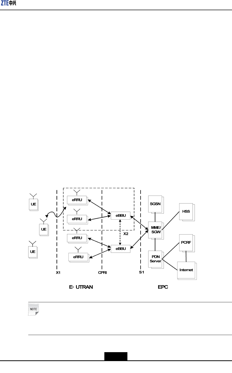
2.2ProductPositioninNetwork
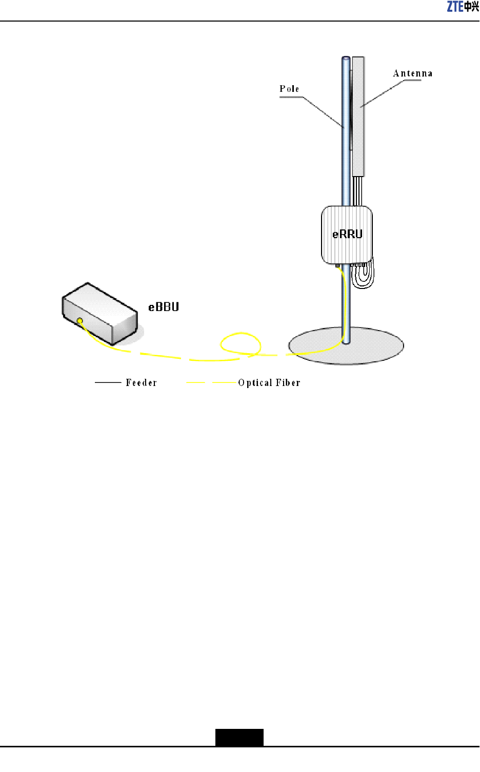
ZXSDRR8882L268isaremoteradiounit(eRRU)ofdistributedeNodeB.Thesignalis
transmittedorreceivedthroughZXSDRR8882L268toandfrombasebandprocessing
unitforfurtherprocessingthroughCPRIinterface.Byapplyingthedistributedsystem,the
feederlosswillbereducedwhentheremoteradiounitispositionedclosetotheantenna.
Thecoverageisenlargedwiththissolution.
Figure2-2ProductLocation
Note:
ZXSDRR8882L268coversR8882L188,R8882L708,R8882L808,andR8882L268.
2-3
SJ-20110104194923-001|2011-01-19(R1.0)ZTEProprietaryandCondential

ZXSDRR8882L268UserManual
2.3ProductFeatures
Multi-ModeeRRU
ZXSDRR8882L268isfullysoftwaredeneddevice.Itsupportsmulti-modeatthesame
frequencybandsimultaneously.Therefore,itfullysatisesoperators’requirementsof
hybridnetworkdeploymentandlongtermevolutionwiththelowestcost.
MIMOSupported,BetterPerformance
R8882L268supports2T4R(licenseneeded),R8882L188,R8882L708,andR8882L808
support2T2R,whichcanoptimizespectrumefciencygreatlyandimprovenetworkuplink
performance.Asaresult,itbringsbettercustomerexperience.
HigherEfciency,LowerTCO
lZXSDRR8882L268’sPAefciencycanreachupto30%thankstothemostadvanced
DohertyPA,DPDlineartechnology.
lItsupportsdynamicadaptivePApowersupplyduetotheoutputpower,whichreduces
powerconsumption.
2.4ProductFunctions
ZXSDRR8882L268istheremoteradiounitofdistributedbasestation.Thesignalis
transmittedorreceivedthroughZXSDRR8882L268to/frombasebandprocessingunit
forfurtherprocessingviastandardCPRIinterface.
Theproductbasicfunctionsarelistedbelow:
lSupportsthecongurationof5MHz,10MHz,15MHzand20MHzscalable
bandwidth.
lR8882L188supports1710MHz~1785MHz(uplink)/1805MHz~1880MHz(downlink).
lR8882L708supports698MHz~716MHz(uplink)/728MHz~746MHz(downlink).
lR8882L808supports832MHz~862MHz(uplink)/791MHz~821MHz(downlink).
lR8882L268supports2500MHz~2570MHz(uplink)/2620MHz~2690MHz(downlink).
lSupports2x2MIMOondownlink.
lSupportsQPSK,16-QAM,64-QAMondownlink,QPSKand16–QAMonuplink.
lSupportstransmissionandreceivepowerdetection.
lSupportsoverloadpowerprotectionforpoweramplier.
lSupportspoweramplierswitchingon/offfunction.
lZXSDRR8882L268softwarefailurewillnotaffecttherunningofeBBUandother
ZXSDRR8882L268swhichareconnectedtoit.
lSupportseldstrengthscanning,temperaturequery,VSWRquery,drycontact,
hardware/softwareresetting.
2-4
SJ-20110104194923-001|2011-01-19(R1.0)ZTEProprietaryandCondential
Chapter2ProductOverview
2.5ProductAppearance
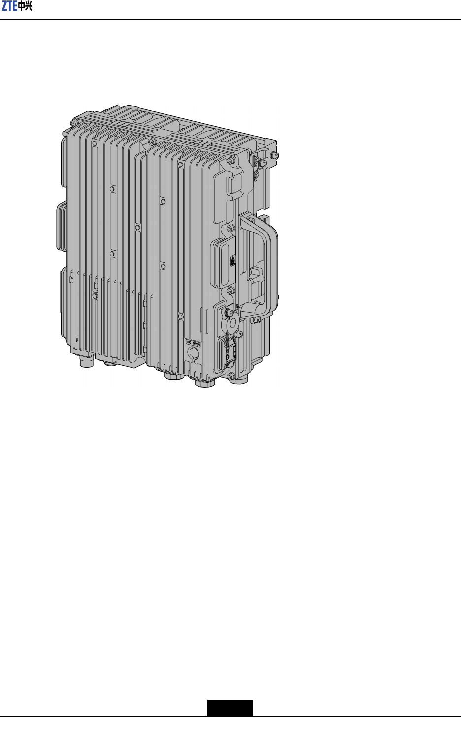
TheappearanceofZXSDRR8882L268isasshowninFigure2-3.
Figure2-3ProductOverallAppearance
2.6InstallationScenario
TheZXSDRR8882L268usuallyinstalledonwalloronpoleorongantry.
2.7ProductNetworking
ZXSDRR8882L268supportsstarnetworkingmodewitheBBU,asshowninFigure2-4.
2-5
SJ-20110104194923-001|2011-01-19(R1.0)ZTEProprietaryandCondential

ZXSDRR8882L268UserManual
Figure2-4StarNetworkingMode
2.8OperationandMaintenanceIntroduction
ZXSDRR8882L268supportssystemoperationandmaintenanceremotelyorlocally.
OperateandMaintainSystemRemotely
RemotelyoperatesandmaintainssystembyusingNetNumenmanagementsystem,as
showninFigure2-5.
Figure2-5OperateandMaintainSystemRemotely
2-6
SJ-20110104194923-001|2011-01-19(R1.0)ZTEProprietaryandCondential
Chapter2ProductOverview
OperateandMaintainSystemLocally
locallyoperatesandmaintainssystembyusingZTE’sLocalMaintenanceTerminal(LMT)
softwarekit,asshowninFigure2-6.
Figure2-6OperateandMaintainSystemLocally
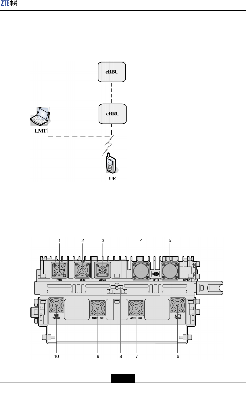
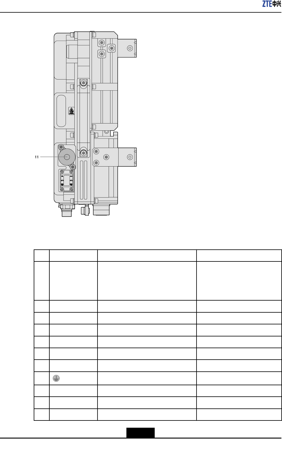
2.9ProductExternalInterfaces
TheZXSDRR8882L268externalinterfacesareshowninFigure2-7andFigure2-8.
Figure2-7ProductExternalInterfacesandGroundingTerminal
2-7
SJ-20110104194923-001|2011-01-19(R1.0)ZTEProprietaryandCondential
ZXSDRR8882L268UserManual
Figure2-8LMTInterface
Table2-1showsthedetaileddescriptionofalltheexternalinterfaces.
Table2-1ProductExternalInterfacesDescription
No.LabelInterface/TerminalInterfacetype/connector
1PWRPowerinterface/1drycontactDCinterface:
ConnectorXCG18T4K1P1-
01+XC18FJJP1-10.5
Sectionareaofcableis1.5mm2
2MON485Serial/2drycontacts8-coressocket(IEC60130-9-ED)
3AISGAISGdeviceinterface8-coresaviationsocket
4OPT1eBBUInterfaceLCtypeopticalinterface
5OPT2ReservedLCtypeopticalinterface
6ANT4(TX1/RX1)AntennaTX/RXinterfaceonchannel150OhmDIN-7/16Connector
7ANT3(RX3)AntennaRXinterfaceonchannel350OhmDIN-7/16Connector
8GroundingT erminal-
9ANT2(RX2)AntennaRXinterfaceonchannel250OhmDIN-7/16Connector
10ANT1(TX0/RX0)AntennaTX/RXinterfaceonchannel050OhmDIN-7/16Connector
11LMTOperationandMaintenanceInterface8P8CEthernetinterface
2-8
SJ-20110104194923-001|2011-01-19(R1.0)ZTEProprietaryandCondential
Chapter2ProductOverview
Note:
TherearenoANT2andANT3interfacesforL708andL808.
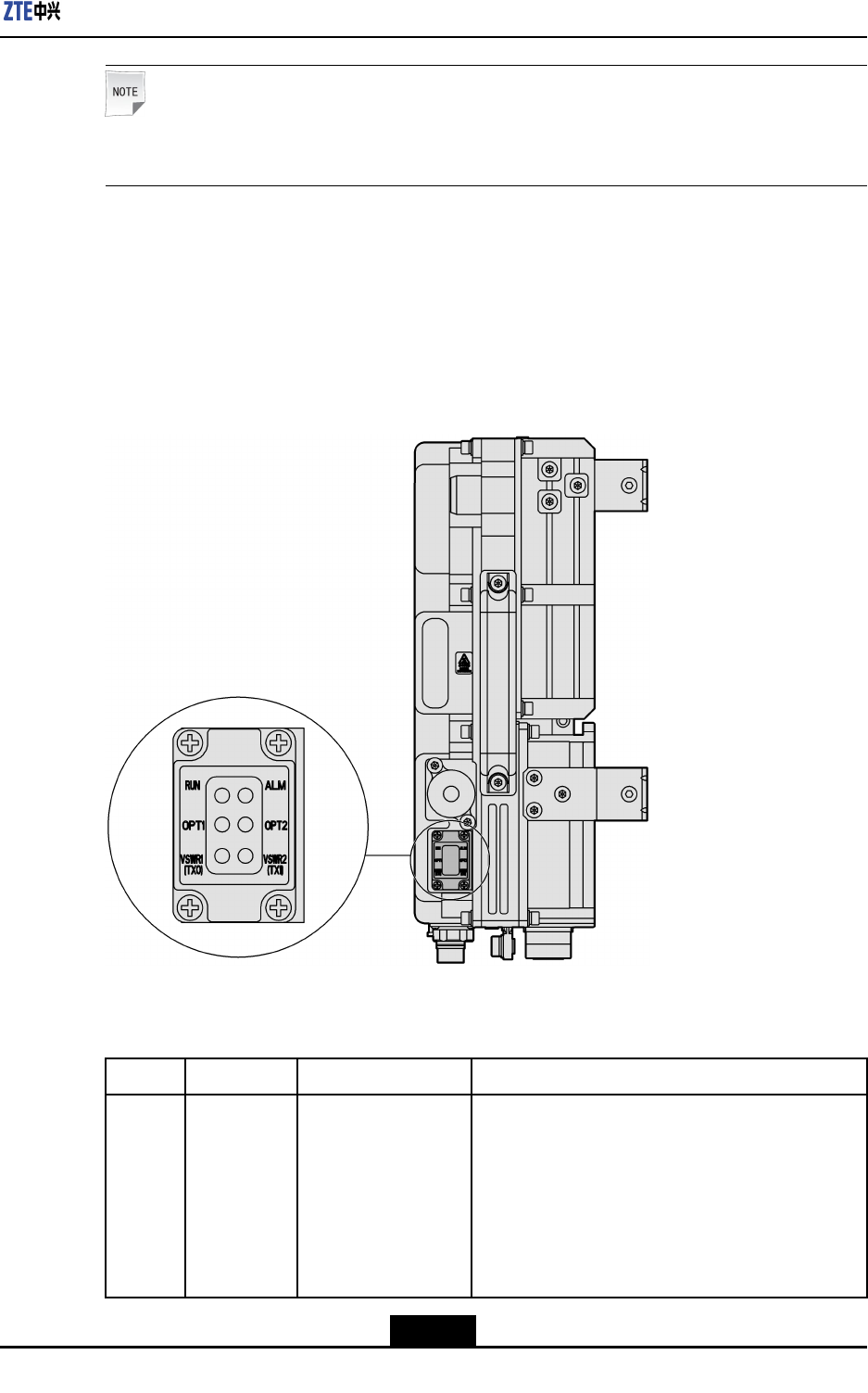
2.10ProductIndicators
ZXSDRR8882L268providessixLEDindicators,whicharelocatedattherightbottom
sideofthedevice.TheLEDindicatorsareusedtoshowproductworkingstatusandalarm
status,asshowninFigure2-9.
Figure2-9ProductIndicators
Table2-2showsthedetailedinformationoftheindicators.
Table2-2ProductIndicatorDescription
NameColorMeaningWorkingMode
RUNGreenRunningstatuslBlinkingevery1.5second:physicallinkinthe
processofinitialization
lBlinkingevery0.07second:thelinkbetween
eBBUandeRRUisintheprocessof
establishment,orthelinkisbroken
lBlinkingevery0.3second:deviceisingood
state
2-9
SJ-20110104194923-001|2011-01-19(R1.0)ZTEProprietaryandCondential

ZXSDRR8882L268UserManual
NameColorMeaningWorkingMode
ALMRedAlarmindicatorlSolidON:thereisalarm
lOFF:thereisnoalarm
OPT1GreenOpticalinterface
runningindicator
lSolidON:physicallinkisgood,logicallinkis
abnormal
lOFF:physicallinkisabnormal
lBlinkingevery0.3second:interfaceisingood
state
OPT2GreenOpticalinterface
runningindicator
lSolidON:physicallinkisgood,logicallinkis
abnormal
lOFF:physicallinkisabnormal
lBlinkingevery0.3second:interfaceisingood
state
VSWR1RedTransmission
channel1VSWR
indicator
lSolidON:thereareVSWRalarms
lOFF:thereisnoVSWRalarm
VSWR2RedTransmission
channel4VSWR
indicator
lSolidON:thereareVSWRalarms
lOFF:thereisnoVSWRalarm
2-10
SJ-20110104194923-001|2011-01-19(R1.0)ZTEProprietaryandCondential
Chapter3
ProuductTechnicalIndices
TableofContents
PhysicalIndices.........................................................................................................3-1
WorkingEnvironment.................................................................................................3-1
Bandwidth..................................................................................................................3-1
PowerRequirements..................................................................................................3-2
PowerConsumption...................................................................................................3-2
TransmissionIndex....................................................................................................3-2
PerformanceIndices..................................................................................................3-2
ElectromagneticCompatibility....................................................................................3-3
Reliability....................................................................................................................3-6
3.1PhysicalIndices
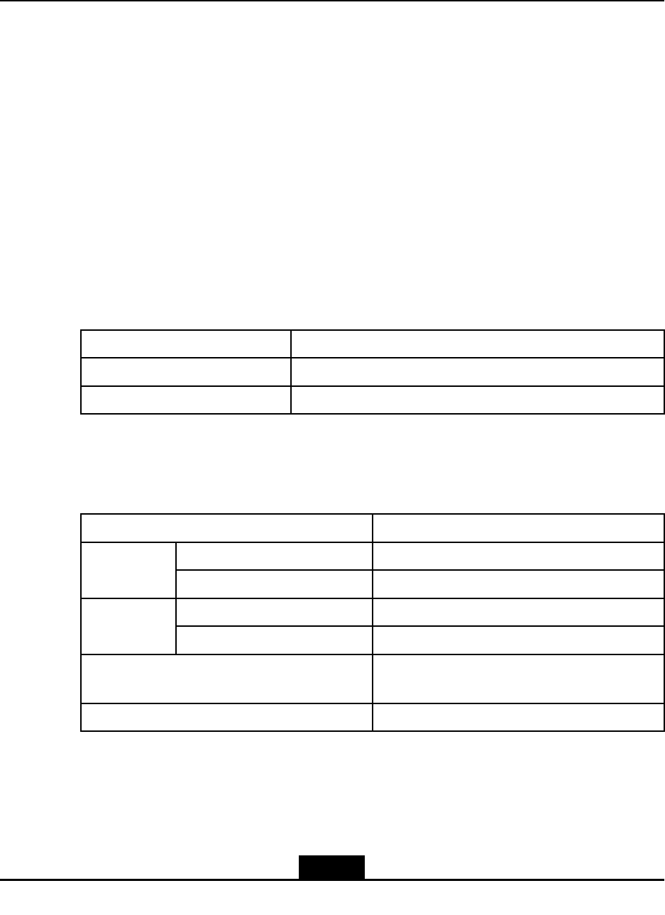
ItemIndex
Dimension380mmx320mmx140mm(HxWxD)
Weight20kg
3.2WorkingEnvironment
ItemIndex
Temperature-40℃~55℃Working
RelativeHumidity5%~100%
Temperature-55℃~70℃Storage
RelativeHumidity10%~100%
GroundLessthan0.1Ωbetweengroundingterminaland
deviceterminal
Waterproof/DustproofIP65
3.3Bandwidth
ZXSDRR8882L268supports5MHz,10MHz,15MHzand20MHz.
3-1
SJ-20110104194923-001|2011-01-19(R1.0)ZTEProprietaryandCondential
ZXSDRR8882L268UserManual
Note:
L708doesnotsupport20MHz.
3.4PowerRequirements
ThepowersupplyoftheZXSDRR8882L268is-48VDC(range:-37VDC~-57VDC).
3.5PowerConsumption
ThemaximumpowerconsumptionofZXSDRR8882L268is330W.
3.6TransmissionIndex
ZXSDRR8882L268connectstoeBBUthroughCPRIinterfaces.Thedetailedinformation
oftheCPRIinterfaceisshowninT able3-1.
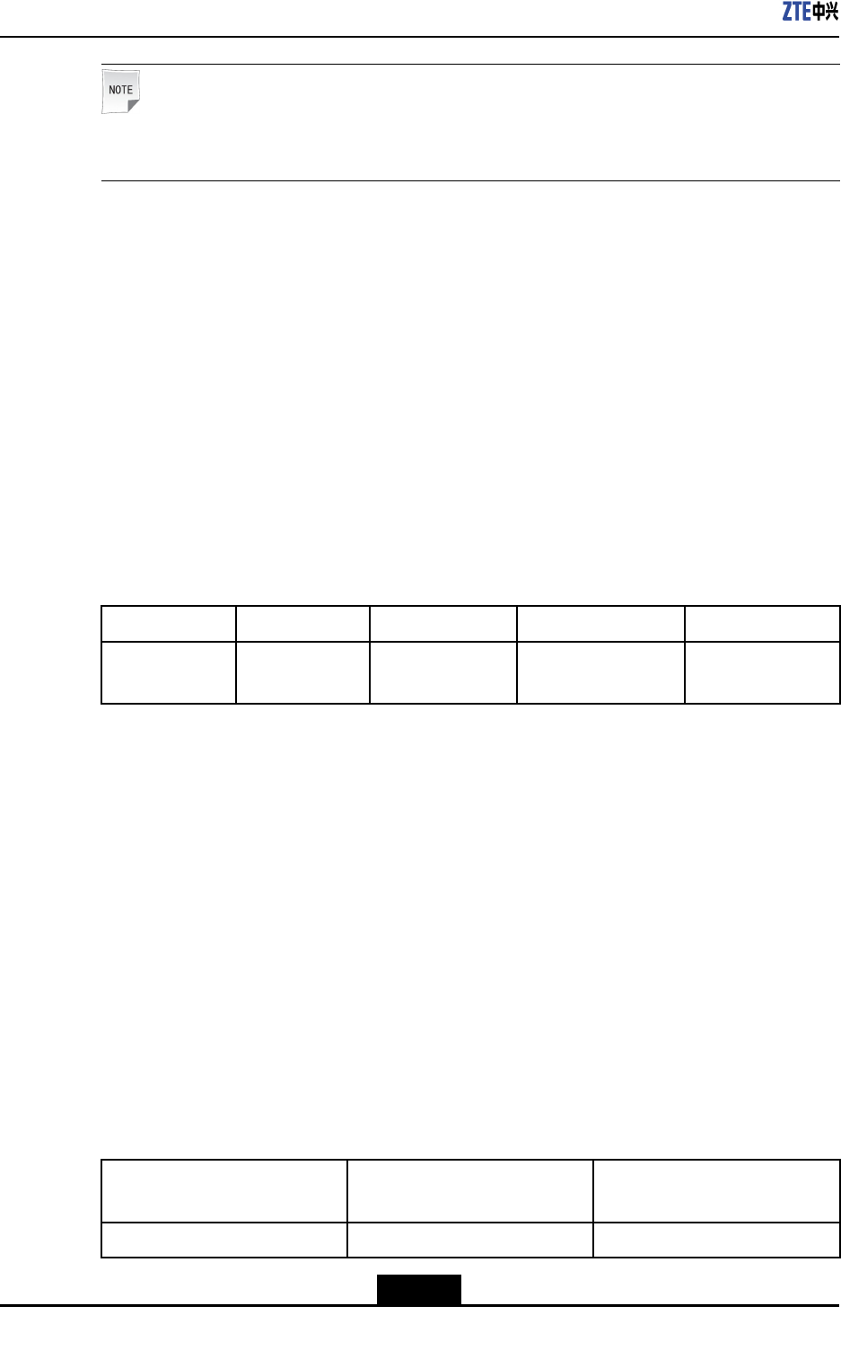
Table3-1CPRIInterfaceIndex
ItemQuantityInterfacetypeSpeedStandard
CPRIinterface2SFP(LC)2x3.072Gbpsor
2x2.4576Gbps
CPRIV4.1
3.7PerformanceIndices
OperationFrequencyBand
TheoperationradiofrequencybandofZXSDRR8882L268is2500MHz~2570
MHz(uplink)/2620MHz~2690MHz(downlink)
OutputPower
TheTOCoutputpowerofZXSDRR8882L268is2x30W.
ReceiverSensitivity
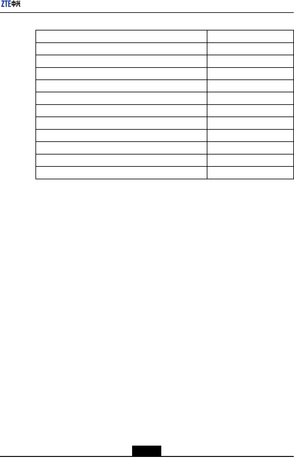
ThereceiversensitivityofZXSDRR8882L268isshowninT able3-2.
Table3-2ReceiverSensitivity
Channelbandwidth(MHz)Referencemeasurement
channel
Referencesensitivitypower
level(dBm)
5/10/15/20FRCA1-3inTable3-3-104
3-2
SJ-20110104194923-001|2011-01-19(R1.0)ZTEProprietaryandCondential
Chapter3ProuductT echnicalIndices
Table3-3FRCParametersforReferenceSensitivityandIn-channelSelectivity
ReferencechannelA1-3
Allocatedresourceblocks25
DFT-OFDMSymbolspersub-frame12
ModulationQPSK
Coderate1/3
Payloadsize(bits)2216
TransportblockCRC(bits)24
CodeblockCRCsize(bits)0
Numberofcodeblocks1
Codedblocksizeincluding12–bitstrellistermination(bits)6732
Totalnumberofbitspersub-frame7200
Totalsymbolspersub-frame3600
3.8ElectromagneticCompatibility
Thedecisionruleusedinthissectionisdescribesasfollows:
1.RuleA
lAcommunicationchannelissetupforthetest,anditisalwaysavailableduring
thetest.
lFERoftheforwardchannelandreversechannelarelessthanorequalto1during
thetest.
lWhenthetesttaskaccomplished,equipmentundertest(EUT)worksnormally
underpre-scheduledmethod,thereisnoinformationlossofusercontrolfunction
andthesaveddata,andthecommunicationchannelisstillavailable.
lIftheEUTisatransmitteronly,testshouldbedoneunderidle-mode,andthere
isnounintentionalradiationduringthetest.
2.RuleB
lAcommunicationchannelissetupforthetest,anditisalwaysavailableduring
test.
lEUTworksnormallyunderpre-scheduledmethod,thereisnoinformationlossof
usercontrolfunctionandthesaveddata,andthecommunicationchannelisstill
available.
lIftheEUTisatransmitteronly,testshouldbedoneunderidle-mode,andthere
isnounintentionalradiationduringthetest.
3.RuleR
Thereisnodevicedamageorinterference(suchassoftwaremalfunctionorprotection
devicemis-operation)duringthetest.TheEUTworksnormallyunderthedened
boundaryaftertransientelectromagneticincident.
3-3
SJ-20110104194923-001|2011-01-19(R1.0)ZTEProprietaryandCondential

ZXSDRR8882L268UserManual
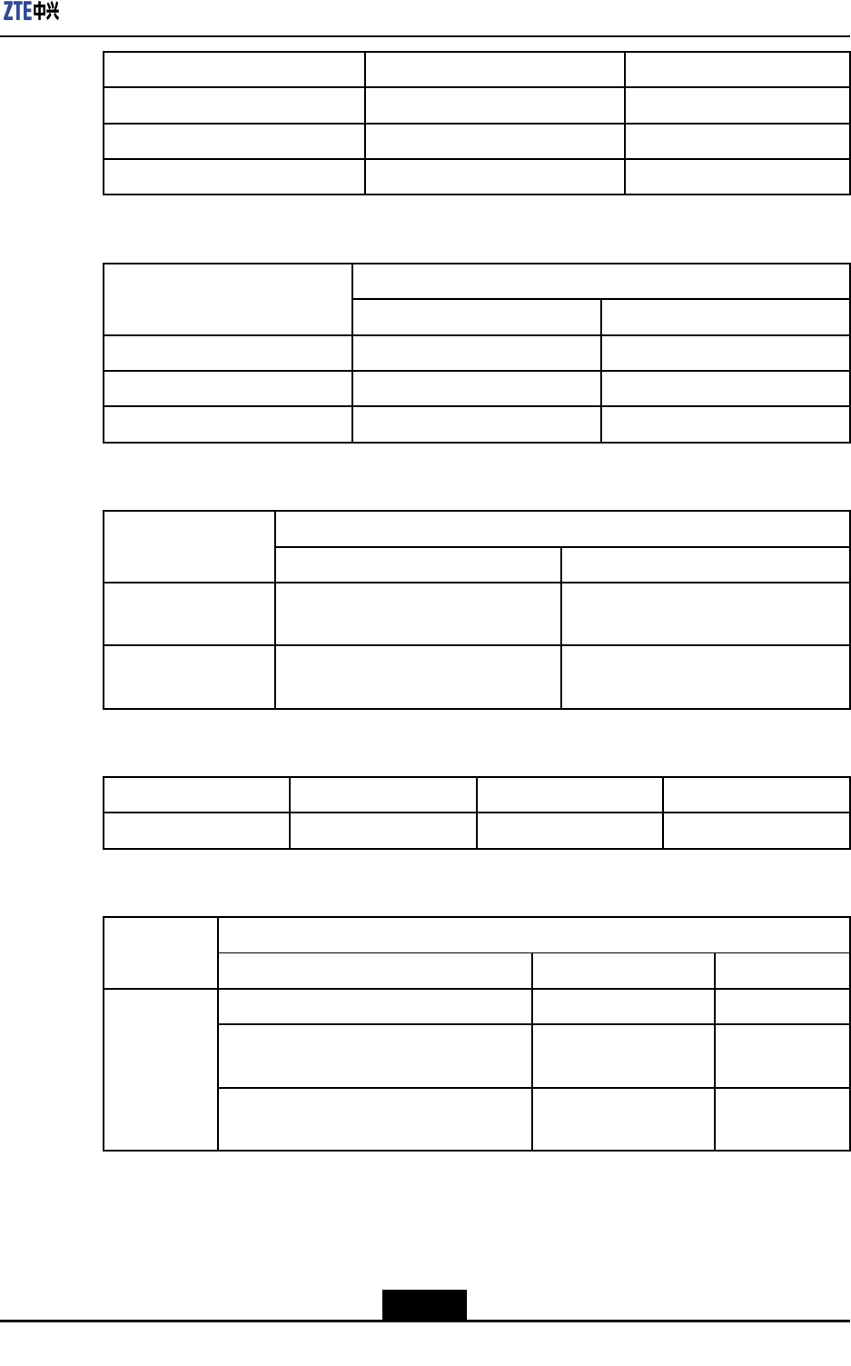
ElectronicStaticDischargeImmunity
ItemContactdischargeAirdischargeDecisionRule
Basictesting6kV8kVRuleB
Enhancedtesting8kV15kVRuleR
RFElectromagneticFieldRadiationImmunity
RangeFeatureFieldStrengthDecisionRule
80MHz~800MHz80%AM(1kHz)10V/mRuleA
800MHz~960MHz80%AM(1kHz)10V/mRuleA
960MHz~1400MHz80%AM(1kHz)10V/mRuleA
1400MHz~2700MHz80%AM(1kHz)10V/mRuleA
2700MHz~6000MHz80%AM(1kHz)10V/mRuleA
ElectricalFastTransientBurstImmunity
ItemVoltageRepetitionFrequencyDecisionRule
Basictest±1kV5kHzRuleB
Enhancedtest±2kV5kHzRuleB
signalgeneratorwaveform5/50ns
LightningTolerance
SignalTypeNominalRequired
Antennafeederport10kA±5times
The10KAprotectionisguaranteedbytheduplexof
theRFmodule.Anexternallightningprotectionunit
isneededforthehigherprotectionotherthan10KA
DCpowerport(externalSPD)20kA±5times,ResidualVoltageislessthan250V.
ShieldedcableisusedfortheR8882remotepower
supply
Signalport—drycontact3KA
Signalport—RS485signal3KA
AISGpower5KA
Signalport—AISG485port3KA
RadiationTransmission
Frequencyrange(MHz)Quasi-peaklimit(dBuV/m)Distance( (
(m) )
)
30~2303010
3-4
SJ-20110104194923-001|2011-01-19(R1.0)ZTEProprietaryandCondential
Chapter3ProuductT echnicalIndices
Frequencyrange(MHz)Quasi-peaklimit(dBuV/m)Distance( (
(m) )
)
230~10003710
1G~3G5010
3G~6G5410
PowerConductedTransmission
Sumlimit(dBuV) Frequencyrange(MHz)
Quasi-peakAveragevalue
0.15~0.5056~6646~56
0.50~55646
5~306050
SignalConductedTransmission
Sumlimit Frequencyrange
Quasi-peakAveragevalue
0.15MHz~0.5MHz84dBuV~74dBuV(Voltage)or40
dBuV~30dBuA(Current)
74dBuV~64dBuV(Voltage)or30
dBuV~20dBuA(Current)
0.5MHz~30MHz74dBuV(Voltage)or30dBuA
(Current)
64dBuV(Voltage)or20dBuA
(Current)
RFElectromagneticFieldConductedImmunity
FrequencyrangeVoltageFeatureDecisionRule
0.15MHz~80MHz10V80%AM(1kHz)RuleA
SurgeImmunity
OpencircuitVoltage Site
TypeWire—WireWire—Ground
DCpower0.51
Longdistancewire(wirelengthlonger
than10meters)
11
Indoor
Shortdistancewire(wirelengthlessthan
10meters)
--
3-5
SJ-20110104194923-001|2011-01-19(R1.0)ZTEProprietaryandCondential

ZXSDRR8882L268UserManual
3.9Reliability
ItemCharacteristics
MTBF≥34,0000hours
MTTR1hour
Availability≥99.999842%
3-6
SJ-20110104194923-001|2011-01-19(R1.0)ZTEProprietaryandCondential
Chapter4
ProductInstallation
TableofContents
SafetyDescription.....................................................................................................4-1
PreparationBeforeInstallation...................................................................................4-6
MountingOnWall.....................................................................................................4-10
MountingOnPole....................................................................................................4-14
MountingOnGantry.................................................................................................4-21
ConnectingCables...................................................................................................4-25
4.1SafetyDescription
4.1.1SafetyGuide
OnlytheprofessionalpersonnelwhohavepassedthetrainingrelatedtoZXSDRR8882
L268canoperateandmaintaintheequipment.
BasicrequirementsonZXSDRR8882L268maintenancepersonnelinclude:
lBefamiliarwithZXSDRR8882L268equipmentprincipleandnetworking;
lHoldcertainnetworkoptimizationskill.
Duringtheoperationandmaintenanceoftheequipment,allthesafetyrulesandrelated
operationproceduresonthesitemustbestrictlyabidedby,toavoidbodyinjuries
orequipmentdamages.Thesafetyprecautionsintroducedinthismanualareonly
supplementarytothelocalsafetyspecications.
ZTEshouldinnowaybeliableforanylossesordamagescausedbyviolationof
theuniversalsafetyoperationrequirementsorthesafetystandardsfordesigning,
manufacturingandusingtheequipment.
4.1.2SymbolDescription
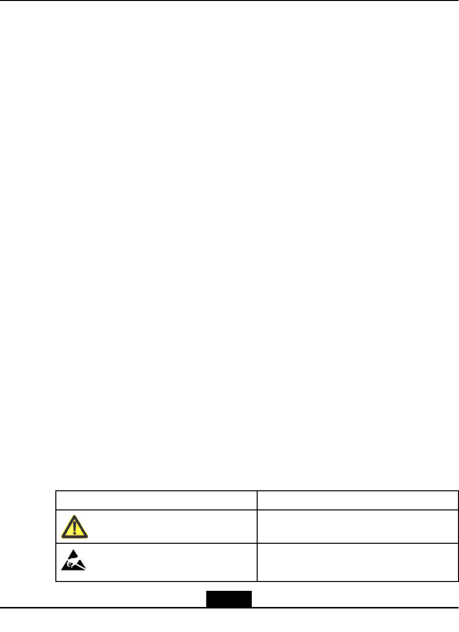
Table4-1showssafetysymbolsanditsmeanings.
Table4-1SafetySymbolsandTheirDescriptions
SafetySymbolsMeaning
Beware!
Bewareofelectrostaticdischarge
4-1
SJ-20110104194923-001|2011-01-19(R1.0)ZTEProprietaryandCondential
ZXSDRR8882L268UserManual
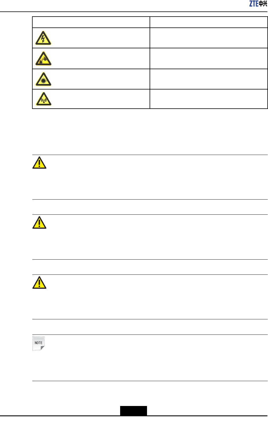
SafetySymbolsMeaning
Warnagainstelectricshock
Cautionagainstscald
Bewareoflaser
Becarefulofmicrowave
Fourtypesofsafetylevelsareavailable:danger,warning,cautionandnote.Totherightof
asafetysymbolisthetextdescriptionofitssafetylevel.Underthesymbolisthedetailed
descriptionaboutitscontents.Theformatsareasfollows.
Danger!
Indicatesanimminentlyhazardoussituationwhich,ifnotavoided,willresultindeathor
seriousinjury.Thissignalwordistobelimitedtothemostextremesituations.
Warning!
Thissignmeansthattheremaybeamajororseriousaccident,equipmentdamageor
interruptionofkeyservicesifyouignorethissafetywarning.
Caution!
Indicatesapotentiallyhazardoussituationwhich,ifnotavoided,couldresultinminoror
moderateinjury.Itmayalsobeusedtoalertagainstunsafepractices.
Note:
ANotestatementisusedtonotifypeopleofinstallation,operation,ormaintenance
informationthatisimportant,butnothazard-related.
4-2
SJ-20110104194923-001|2011-01-19(R1.0)ZTEProprietaryandCondential
Chapter4ProductInstallation
4.1.3SafetyInstructions
ElectricalSafety
Danger!
Neverconnectordisconnectanyhotpowercables.Attheinstantwhenpowercables
touchconductors,electricsparksorarcsmayoccur,whichmaycausereoreyeinjury.
Turnoffthepowersupplybeforeinstallingorremovingapowercable.
Makesurethecablesandthecablelabelsmatchthepracticalinstallationconditionsbefore
connectingthem.
Warning!
Donotdrillanyholesonthecabinetonyourown.Improperdrillingmaydamagethewiring
andcablesinsidethecabinetandthemetalscrapsproducedduringthedrillingwillcause
shortcircuitsinthecircuitboardsiftheyenterthecabinet.
StaticElectricity
Caution!
Thestaticelectricitygeneratedbyhumanbodycandamagetheelectrostatic-sensitive
componentsonthecircuitboard,suchasthelargescaleintegratedcircuit(IC).
Accumulatedelectrostaticcharges(ESC)derivefromfrictioncreatedbyhumanbody
movements.Inadryenvironment,thestaticvoltagecarriedbyahumanbodycanbe
upto30kV,andcanremaininthehumanbodyforalongtime.Whenanoperatorwho
carriesstaticelectricitytouchesacomponent,hewilldischargeelectricitythroughthe
component,thusdamagingthecomponent.
Beforetouchinganyequipmentorholdingtheboard,circuitboard,andICchip,wearthe
antistaticwriststrapandmaketheotherendofitbewellgrounded.Thishelpsavoid
damagingelectrostatic-sensitivecomponentsbythestaticelectricityofhumanbody.
4-3
SJ-20110104194923-001|2011-01-19(R1.0)ZTEProprietaryandCondential
ZXSDRR8882L268UserManual
Laser
Warning!
Donotgazeatthelaserbeamfromtheopticaltransceiverorinsidetheopticalber;
otherwise,youreyesmaybedamaged.
HighTemperature
Danger!
Thesurfacetemperatureofsomedevicesisquitehigh,sodonottouchthemtoavoida
scaldinjury.
HotSurface
No-Touching!
Temperaturesexceedingthelimitsarepermittedprovidedthatthefollowingconditionsare
met:
–unintentionalcontactwithsuchapartisunlikely,and
-theparthasamarkingindicatingthatthispartishot.Itispermittedtousethesymbol
(IEC60417-5041(DB:2002-10))toprovidethisinformation.
HoistingHeavyObjects
Warning!
Donotwalkaboutrightundertheboomandthehoistedobjectswhentheyarebeing
hoisted.
lWhendisassemblingheavyequipment,ormovingandreplacingequipment,make
surefacilitieswithproperhoistingcapabilityareinplace.
lThepersonnelthathoisttheequipmentshouldhavereceivednecessarytrainingand
acquiredthecorrespondingqualication,andthehoistingtoolsshouldhavebeen
checkedandbecomplete.
4-4
SJ-20110104194923-001|2011-01-19(R1.0)ZTEProprietaryandCondential
Chapter4ProductInstallation
lMakesurethatthehoistingtoolsarexedrmlytoaxtureorawallthatcanbearthe
weightforthehoisting.
lUsebriefcommandstopreventmisoperation.
Plugging/UnpluggingaModule
Here,modulesincludeboardsandsubracks.
Caution!
lOperatorsmustweartheantistaticwriststrap.
lDonotplugamodulewithgreatforcelestthatthepinsonthebackplanebebent.
lPlugthemodulerightintotheslotandavoidcontactbetweenthemoduleandthe
circuitfacelestthatanyshortcircuitoccur.
lDonottouchthemodulecircuits,components,connectorsandwiringslotswhen
holdingamodule.
lRFmoduleisveryhotduringoperation,soyoushouldbecarefulon
plugging/unplugging.
Personnel
Caution!
Non-professionalsshouldnotmaintainordebugtheinteriorofanyequipmentunless
instructedbyprofessionalsonsite.
Replacingthepartsormodifyingtheequipmentmaygiverisetoextradanger.Therefore,
neverreplaceanypartsormodifytheequipmentbyanymeansunlessotherwise
authorized.Toensureyoursafety,pleasecontactZTECorporationifyouhaveany
problem.
4.1.4HoistingOperationInstructions
IfitisrequiredtohoisteRRUtothetower,refertothefollowinginstructions.
lNaturalconditionsforhoistingoperationaresatised,suchasnofogandhighvisibility.
Thehoistingoperationisprohibitedinwindy,snowy,orrainydays.
lToolsforhoistingoperationareavailable,suchasthehoistingrope(withabearing
capacityof100kg)andthecrownblock,andthecrownblockisrmlyinstalledin
appropriatepositiononthetower.
lOpenthepackagetocheckifthecabinetisingoodcondition.Hoistthecabinettothe
toweraftertheinspection.
Performthefollowingstepsforhoistingoperation.
4-5
SJ-20110104194923-001|2011-01-19(R1.0)ZTEProprietaryandCondential

ZXSDRR8882L268UserManual
leRRUhandlecannotbeusedtobindthehoistingrope.
lPriortohoisting,carefullycheckitagain,includingiftheboundisrmandthebracket
mountingscrewsaretightened.
lItisstrictlyprohibitedtousesteelwireropeasthehoistingrope.
lDuringthehoistingprocedure,irrelevantpersonisprohibitedtostandsurroundingthe
tower,especiallyundertheeRRU,toavoidunexpectedinjury.
4.2PreparationBeforeInstallation
4.2.1PersonnelPreparation
Theeldengineeringsupervisorisinchargeofthetrainingandmanagementofinstallation
personnel,tomakesuretheinstallationisperformedcorrectlyandcontrolinstallation
quality.Theinstallationpersonnelperformtheinstallation.
RequirementsonEngineeringSupervisor
lTheengineeringsupervisorshouldhavequalitycontrolability.
lTheengineeringsupervisorshouldhavereceivedcorrespondingZTEtrainingand
obtainedcertication.
lTheengineeringsupervisorshouldbefamiliarwiththematerials,toolsandoperation
methodsusedintheinstallation.
lTheengineeringsupervisorshouldbefamiliarwiththeinstallationowandinstallation
methodsofeachcomponent.
lTheengineeringsupervisorshouldfollowthe“SafetyFirst”principle,toensurethe
smoothcompletionofinstallation.
RequirementsonInstallationPersonnel
lTheinstallationpersonnelshouldhavereceivedcorrespondingZTEtrainingand
obtainedcertication.
lTheinstallationpersonnelshouldbehealthy,havenotdrunkalcohol.
lTheinstallationpersonnelshouldfollowthesafetyinstructionsoftools,andusesafety
belts.
lTakecareoftheoperationmachineryandtoolstopreventthemfromfalling.
lTheinstallationpersonnelshouldnotwearlooseclothesandslipperyshoes.
4.2.2ContainerofZXSDRR8882L268
ZXSDRR8882L268usescartonsforpacking.TheZXSDRR8882L268cabinetis
wrappedbyEPEpolyfoamandthenputintothecarton,asshowninFigure4-1.
4-6
SJ-20110104194923-001|2011-01-19(R1.0)ZTEProprietaryandCondential
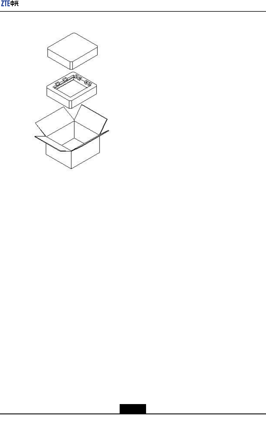
Chapter4ProductInstallation
Figure4-1PackingofZXSDRR8882L268
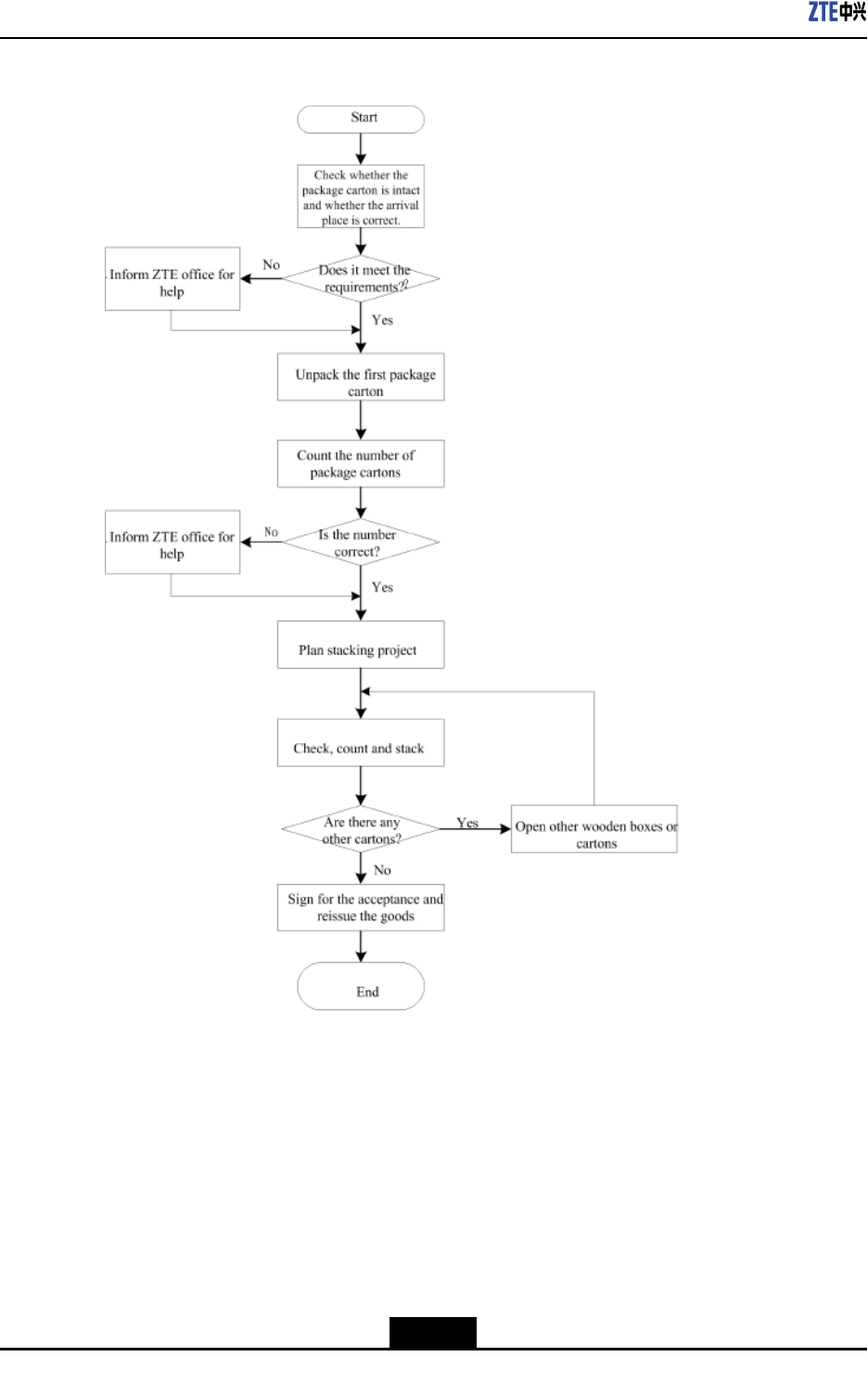
4.2.3UnpackingandCheckingFlow
Figure4-2showstheowofunpackingandchecking.RefertoUnpackingandChecking
ManualintheZXSDRR8882L268engineeringmaterialsfordetailedstepsand
precautions.
4-7
SJ-20110104194923-001|2011-01-19(R1.0)ZTEProprietaryandCondential
Chapter4ProductInstallation
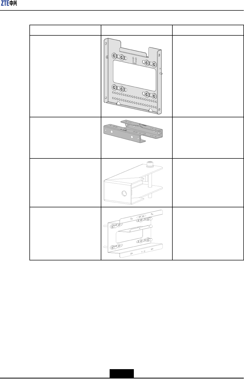
Table4-2InstallationAccessoriesDescription
NameAppearanceDescription
Wall-mountingcomponentsItisusedtomountZXSDR
R8882L268onthewall
PoleMountingClipsItisusedtomountwallmounting
componentsonthepole,and
theZXSDRR8882L268is
mountedonwallmounting
components
Expansionmounting
components
Itisusedtomountthethird
ZXSDRR8882L268onthewall
mountingcomponents
LPUmountingcomponentsItisusedtomountLPUonthe
pole
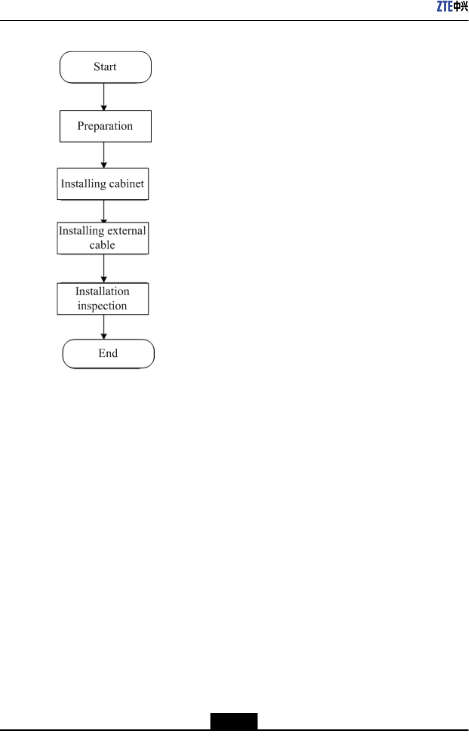
4.2.5InstallationFlow
Figure4-3showstheinstallationow.
4-9
SJ-20110104194923-001|2011-01-19(R1.0)ZTEProprietaryandCondential
ZXSDRR8882L268UserManual
Figure4-3InstallationFlow
4.3MountingOnWall
Prerequisite
BeforeinstallingZXSDRR8882L268,youshouldatleastleavethefollowingspacefor
productfuturemaintenance.
lFrontside:600mm
lBackside:40mm
lleftandrightside:100mm
lUPanddownside:250mm
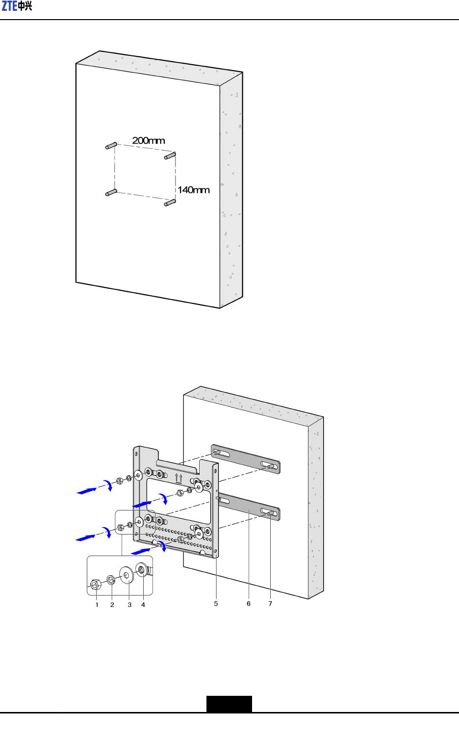
Steps
1.Markoninstallationpositionsbasedonlayoutmarkingtemplateonwall,asshownin
Figure4-4,andthendrillingholes.
4-10
SJ-20110104194923-001|2011-01-19(R1.0)ZTEProprietaryandCondential
Chapter4ProductInstallation
Figure4-4TemplateHolePosition
2.Fixthewall-mountingcomponentsontothewallrmlywiththebolts,asshownin
Figure4-5.
Figure4-5InstallingWall-mountingComponents
1.HexBolt
2.SpringWasher
3.FlatWasher
4.InsulationWasher
5.Wall-Mounting
components
6.InsulationPlate
7.ExpansionBolt
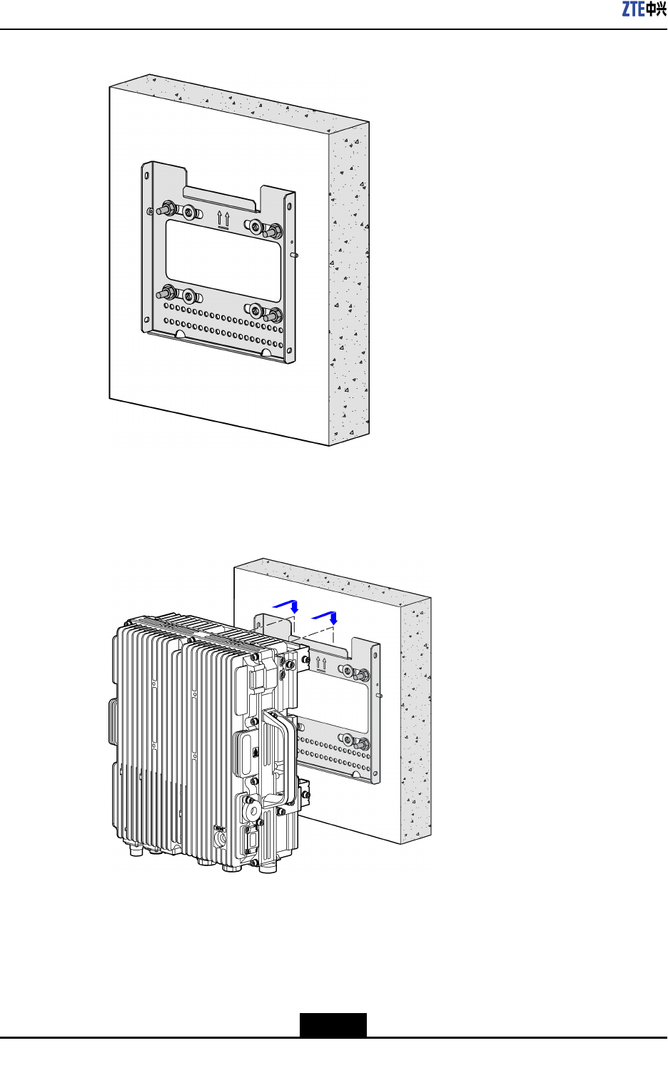
Thewall-mountingcomponentsisinstalledonthewall,asshowninFigure4-6.
4-11
SJ-20110104194923-001|2011-01-19(R1.0)ZTEProprietaryandCondential
ZXSDRR8882L268UserManual
Figure4-6Wall-mountingComponentsOnWall
3.Hungthedeviceonthewall-mountingcomponentsonthenotchdepartment,asshown
inFigure4-7.
Figure4-7HungDeviceOnTheWall-mountingComponents
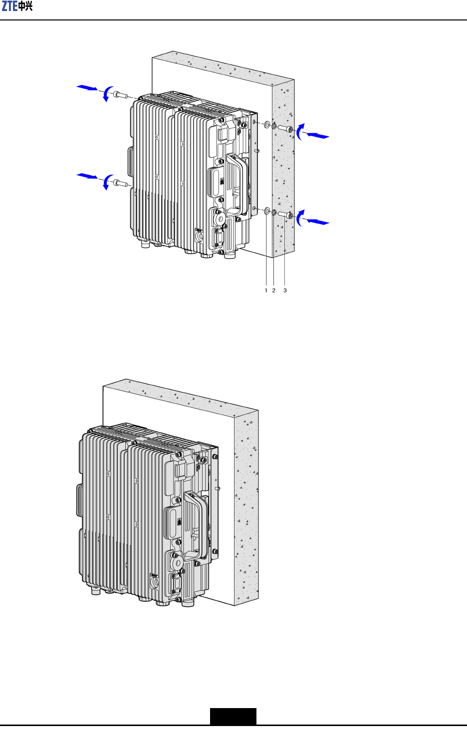
4.MounttheZXSDRR8882L268ontothewall-mountingcomponents,andthenfasten
itwiththeM6bolts,asshowninFigure4-8.
4-12
SJ-20110104194923-001|2011-01-19(R1.0)ZTEProprietaryandCondential
ZXSDRR8882L268UserManual
4.4MountingOnPole
4.4.1One-To-OneMounting
Steps
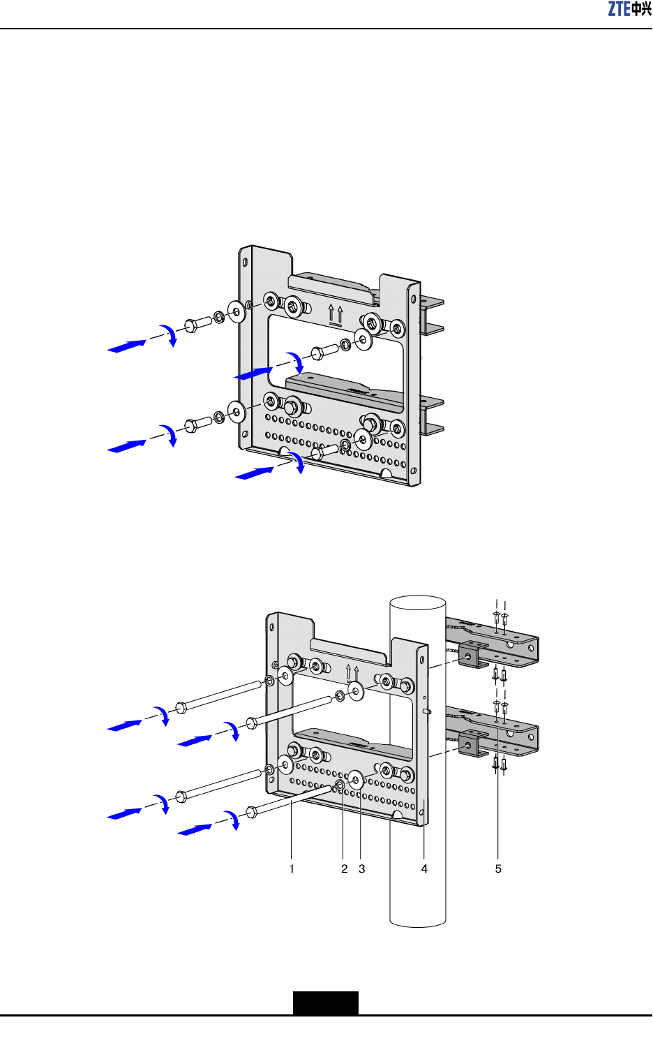
1.Fixingthewall-mountingcomponentsandpolecliptogether,asshowninFigure4-10.
Figure4-10FixingWall-mountingcomponentsandPoleClips
2.Fixingthewall-mountingcomponentsandpoleclipsonthepole,asshowninFigure
4-11.
Figure4-11FixingWall-mountingComponentsandPoleClipsOnPole
1.Bolt
2.Springwasher
3.Flatwasher
4.Wall-mounting
components
5.PoleClips
4-14
SJ-20110104194923-001|2011-01-19(R1.0)ZTEProprietaryandCondential
Chapter4ProductInstallation
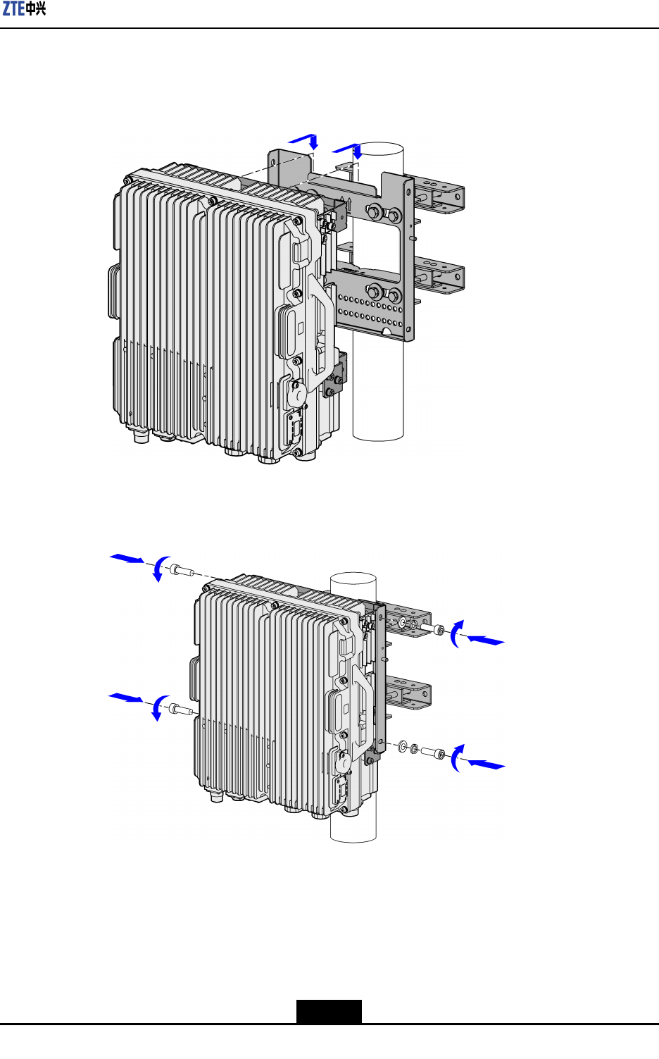
3.Hungthedeviceonthenotchpartofthewall-mountingcomponents,asshownin
Figure4-12.
Figure4-12HungtheDeviceOntheWall-mountingComponents
4.Fixingthedeviceonthewall-mountingcomponents,asshowninFigure4-13.
Figure4-13FixingTheDeviceOnTheWall-mountingComponents
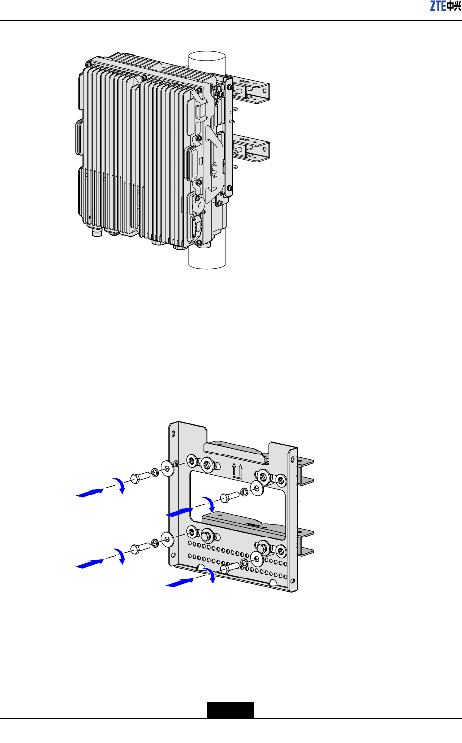
ZXSDRR8882L268isinstalledrmlyonthepole,asshowninFigure4-14.
4-15
SJ-20110104194923-001|2011-01-19(R1.0)ZTEProprietaryandCondential
ZXSDRR8882L268UserManual
Figure4-14ZXSDRR8882L268IsInstalledOnPole
–EndofSteps–
4.4.2One-To-TwoMounting
Steps
1.Fixingthewall-mountingcomponentsandpolecliptogether,asshowninFigure4-15.
Figure4-15FixingWall-mountingcomponentsandPoleClips
2.Fixingthewall-mountingcomponentsandpoleclipsonthepole,asshowninFigure
4-16.
4-16
SJ-20110104194923-001|2011-01-19(R1.0)ZTEProprietaryandCondential
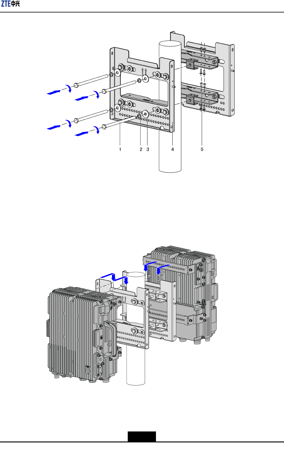
Chapter4ProductInstallation
Figure4-16FixingWall-mountingComponentsandPoleClipsOnPole
1.Bolt
2.Springwasher
3.Flatwasher
4.Wall-mounting
components
5.PoleClips
3.Hungthedevicesonthenotchpartofthewall-mountingcomponentsrespectively,as
showninFigure4-17.
Figure4-17HungtheDevicesOntheWall-mountingComponents
4.Fixingthedevicesonthewall-mountingcomponents,asshowninFigure4-18.
4-17
SJ-20110104194923-001|2011-01-19(R1.0)ZTEProprietaryandCondential
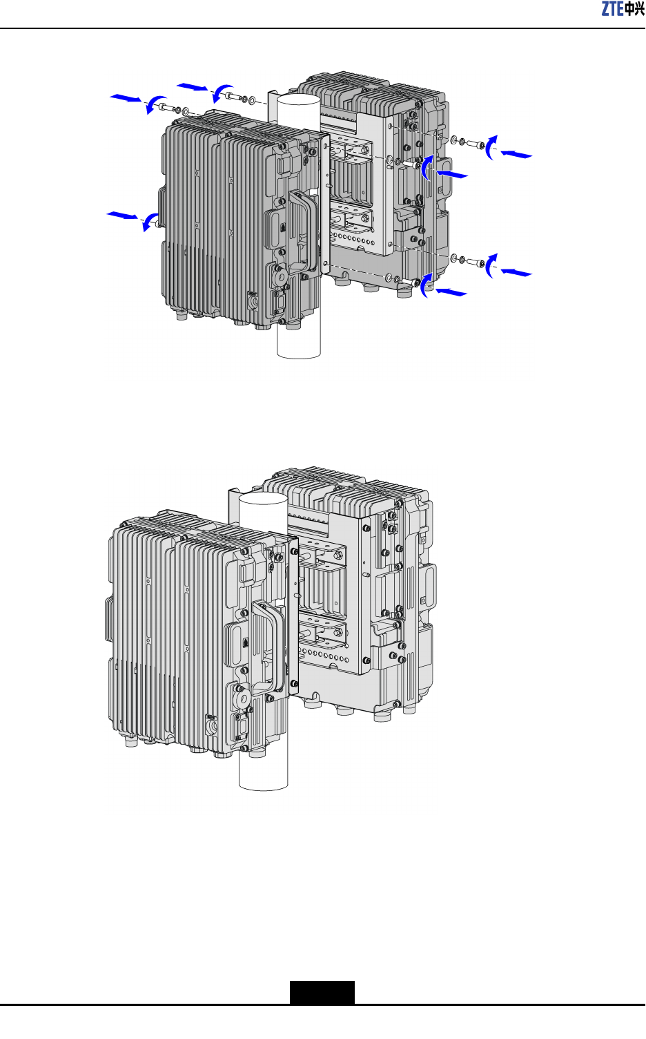
ZXSDRR8882L268UserManual
Figure4-18FixingTheDevicesOnTheWall-mountingComponents
ZXSDRR8882L268areinstalledrmlyonthepole,asshowninFigure4-19.
Figure4-19ZXSDRR8882L268areInstalledOnPole
–EndofSteps–
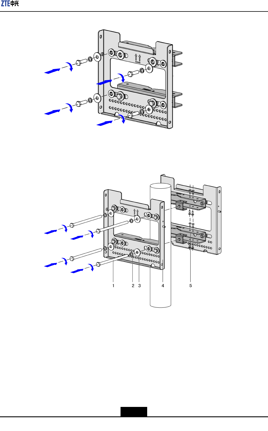
4.4.3One-To-ThreeMounting
Steps
1.Fixingthewall-mountingcomponentsandpolecliptogether,asshowninFigure4-20.
4-18
SJ-20110104194923-001|2011-01-19(R1.0)ZTEProprietaryandCondential
Chapter4ProductInstallation
Figure4-20FixingWall-mountingcomponentsandPoleClips
2.Fixingthewall-mountingcomponentsandpoleclipsonthepole,asshowninFigure
4-21.
Figure4-21FixingWall-mountingComponentsandPoleClipsOnPole
1.Bolt
2.Springwasher
3.Flatwasher
4.Wall-mounting
components
5.PoleClips
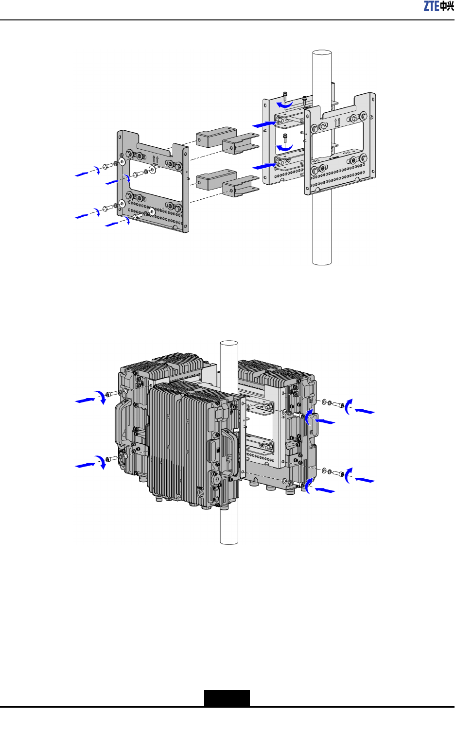
3.Fixingthethirdwall-mountingcomponentsbyusingtheexpansioncomponentstothe
othertwoones,asshowninFigure4-22.
4-19
SJ-20110104194923-001|2011-01-19(R1.0)ZTEProprietaryandCondential
ZXSDRR8882L268UserManual
Figure4-22FixingTheThirdWall-mountingComponents
4.Hungdevicesonthenotchpartofthewall-mountingcomponentsrespectively,as
showninFigure4-23.
Figure4-23HungtheDevicesOntheWall-mountingComponents
ZXSDRR8882L268areinstalledrmlyonthepole,asshowninFigure4-24.
4-20
SJ-20110104194923-001|2011-01-19(R1.0)ZTEProprietaryandCondential
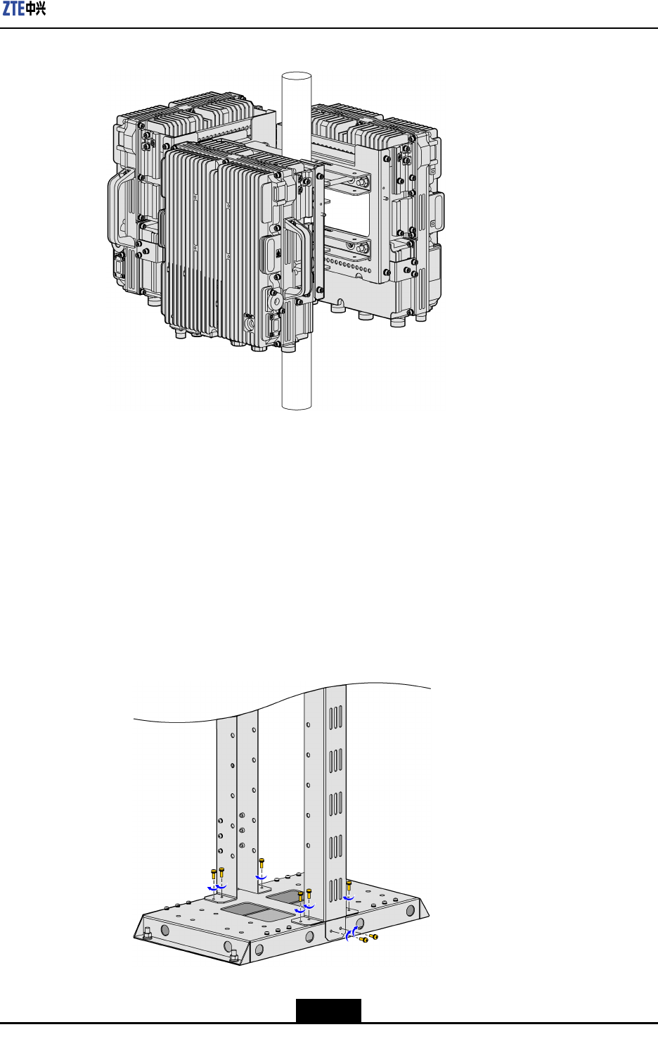
Chapter4ProductInstallation
Figure4-24ZXSDRR8882L268AreInstalledOnPole
–EndofSteps–
4.5MountingOnGantry
Steps
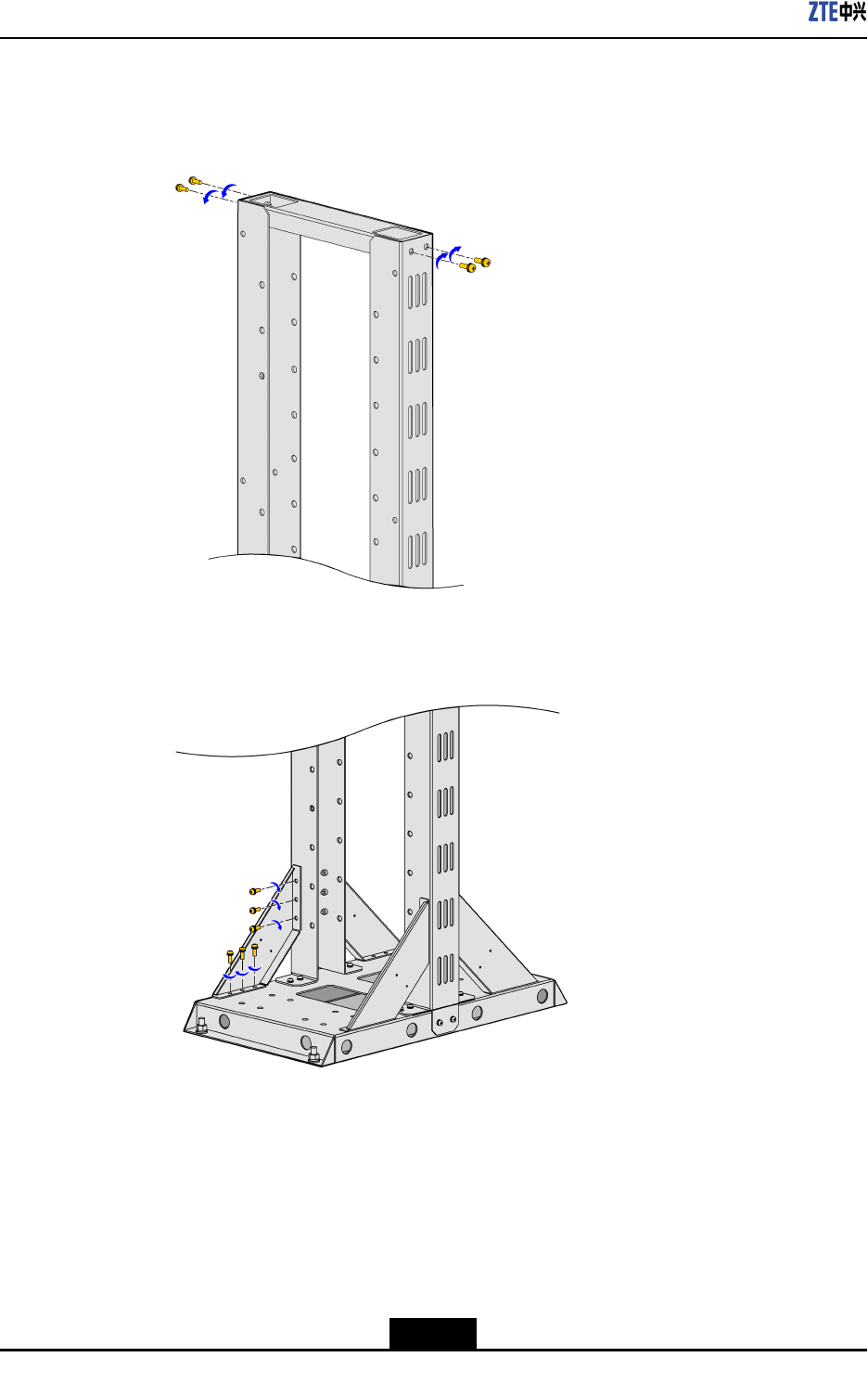
1.Assemblethegantry.
a.InstalltheverticalshaftandthebottomplatebyusingtheM5x16screw,asshown
inFigure4-25.
Figure4-25InstallingTheVerticalShaftAndTheBottomPlate
4-21
SJ-20110104194923-001|2011-01-19(R1.0)ZTEProprietaryandCondential
ZXSDRR8882L268UserManual
b.FastentheverticalshaftandthecoverplatebyusingtheM5x16screw,asshown
inFigure4-26.
Figure4-26FastenTheVerticalShaftAndTheCoverPlate
c.InstalltheslantedrackbyusingtheM5x16screw,asshowninFigure4-27.
Figure4-27InstallingTheSlantedRack
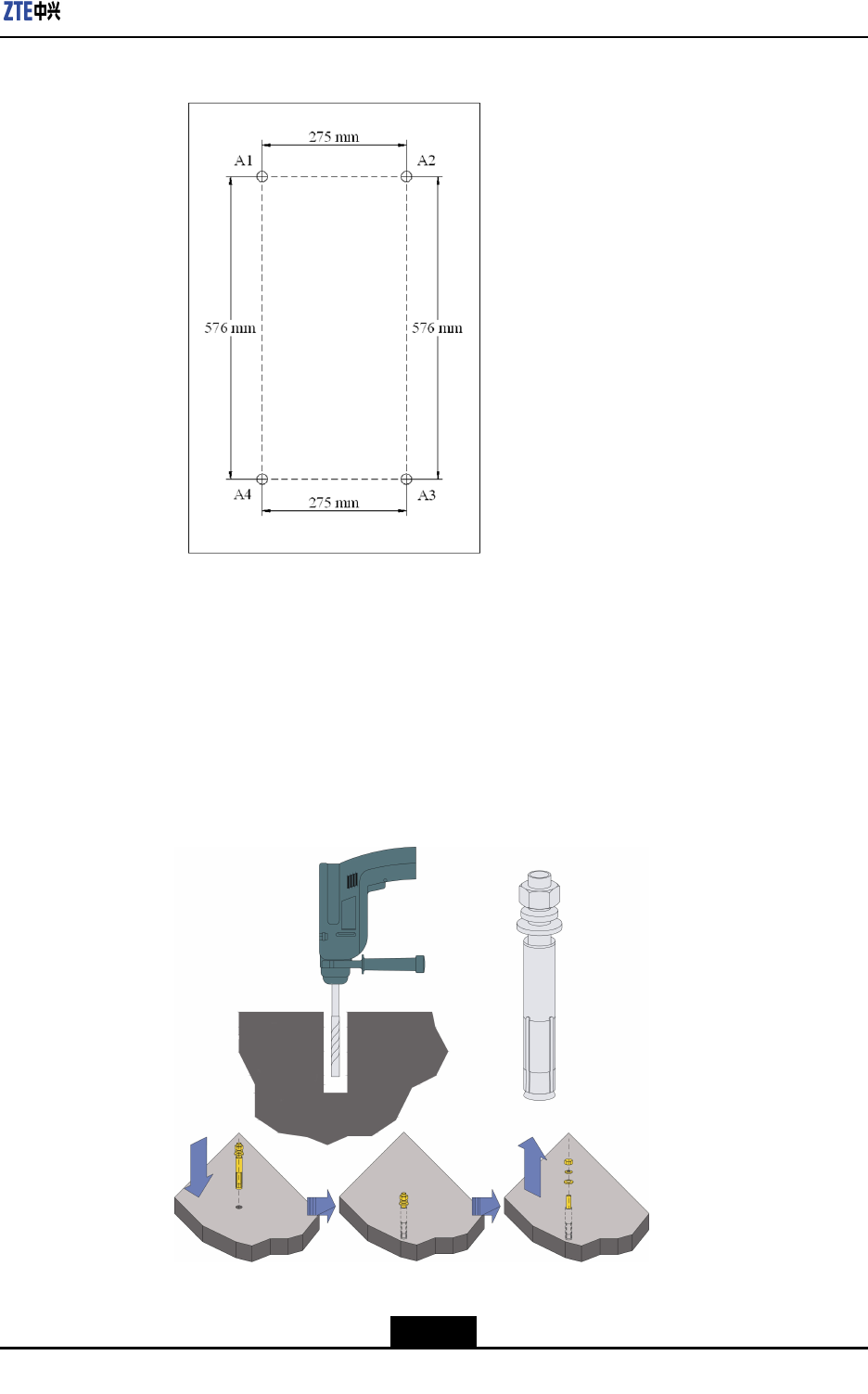
2.Drillholes
a.Accordingtotheengineeringdesigndrawing,determinetheinstallationposition
ofthegantryandmarkinstallationholesbyusingthemarkingpen.Figure4-28
showstheinstallationholesofthegantry.
4-22
SJ-20110104194923-001|2011-01-19(R1.0)ZTEProprietaryandCondential
Chapter4ProductInstallation
Figure4-28MarkingTheDrillingHolesPosiotion
b.Drillholesbyusingtheelectricpercussiondrill(drillbit:φ12)attheplaceswhere
installationholesaremarked.Atthesametime,usethevacuumcleanertoremove
thedustgeneratedduringthedrillingofholes.
c.Puttheexpansionsleeveontothemetalconeoftheexpansionbolt,fastenthe
nutslightly,striketheexpansionboltintotheinstallationholebyusingtherubber
hammer,fastenthenuttightlytomaketheboltfullyexpanded,andthenremove
thenut,asshowninFigure4-29.
Figure4-29InstallingTheExpansionBolt
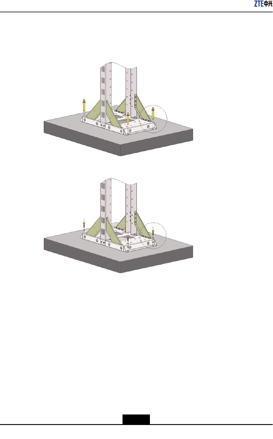
3.Installthegantry.
4-23
SJ-20110104194923-001|2011-01-19(R1.0)ZTEProprietaryandCondential
ZXSDRR8882L268UserManual
Ifthegantryisinstalledontheconcreteoor,usetheM10x100expansionbolt,as
showninFigure4-30;ifthegantryisinstalledonthewoodenoor,usetheM10x40
tappingscrew,asshowninFigure4-31.
Figure4-30InstallingTheGantryOnTheConcreteFloor
Figure4-31InstallingTheGantryOnTheWoodenFloor
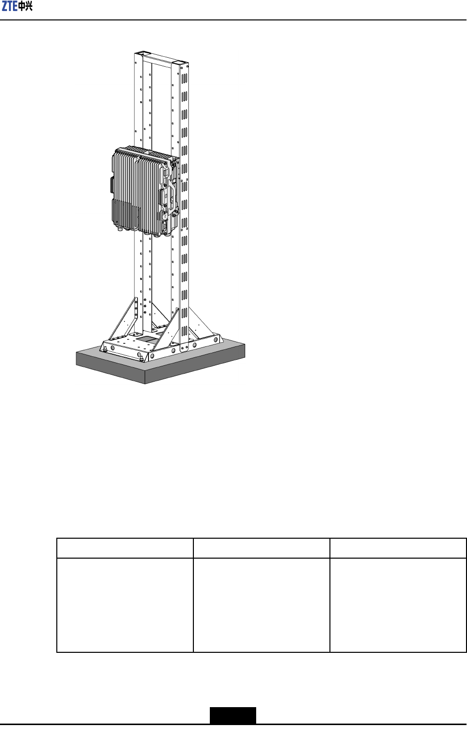
4.Installthewall-mountingcomponentsonthegantry.
5.InstalltheZXSDRR8882L268onthewall-mountingcomponents.Thedeviceis
installedrmlyonthegantry,asshowninFigure4-32.
4-24
SJ-20110104194923-001|2011-01-19(R1.0)ZTEProprietaryandCondential
Chapter4ProductInstallation
Figure4-32ZXSDRR8882L268IsInstalledOnGantry
–EndofSteps–
4.6ConnectingCables
4.6.1ConnectionofExternalCables
Table4-3describestheconnectionofZXSDRR8882L268externalcables.
Table4-3ConnectionofZXSDRR8882L268ExternalCables
CabletypeConnectionrelationDescription
PowercableConnectstheZXSDRR8882
L268powerinterfacetothe
powersupplyequipment
interface
Oneendiscircular6-core
cableconnector(hole)with
plasticcover,theotherendis
reservedforpowercable.The
lengthofcableisbasedonthe
engineeringsurvey.
4-25
SJ-20110104194923-001|2011-01-19(R1.0)ZTEProprietaryandCondential

ZXSDRR8882L268UserManual
GroundingcableConnectsoneZXSDRR8882
L268groundbolttothecopper
bar
Thegroundingcableismade
upofstrandsofame-retardant
wire.Thecrosssectional
areaofZXSDRR8882L268
groundingcableis25mm2.
Copperlugsarecrimpedatboth
endsofthegroundingcable.
FiberConnectstoeBBUandfor
ZXSDRR8882L268cascading
too.
Devicesupportssinglemode/
multi-modeopticalbercable.
EnvironmentmonitorcableConnectstheZXSDRR8882
L268environmentmonitor
interfacetotheexternalmonitor
componentsorthedrycontact.
Fortheenvironmentmonitor
cable,endAisPINheader.
EndB,with3mlengthintotal,
ismadedependingontheeld
engineeringconditions.
AISGcableConnectstheZXSDRR8882
L268debugginginterface
(AISG)
AISGisusedtoprovidethe
RS485signalandtheDC
voltageoutput.
AntennajumperConnectsZXSDRR8882L268
tomainfeeder
TheRFjumperusuallyuses
thenished1/2″jumperwith
2mlength.Thejumpercan
becustomizeddependingon
actualconditions.Oneend
ofthejumperisNconnector
(male)andtheotherendisDIN
connector(female).
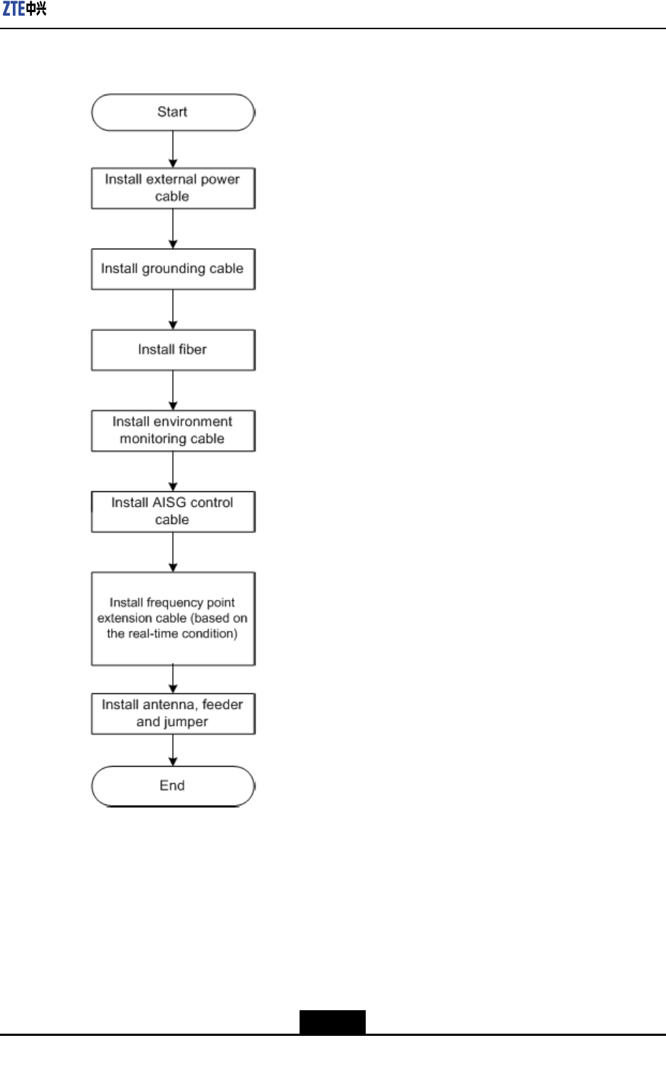
4.6.2ExternalCableInstallationFlow
Figure4-33liststheinstallationowofexternalcable.Thisowcanbeadjustedbasedon
actualconditions.
4-26
SJ-20110104194923-001|2011-01-19(R1.0)ZTEProprietaryandCondential
Chapter4ProductInstallation
Figure4-33ExternalCableInstallationFlow
4.6.3InstallingPowerCable
Context
-48VDCisusedforZXSDRR8882L268cabinet.Apowercableisprovidedforthe
equipment.Oneendiscircular6-corecableconnector(hole)withplasticcover,theother
endisreservedforpowercable.Thelengthofcableisbasedontheengineeringsurvey.
4-27
SJ-20110104194923-001|2011-01-19(R1.0)ZTEProprietaryandCondential
ZXSDRR8882L268UserManual
Figure4-34showsthestructureofZXSDRR8882L268powercable.
Figure4-34StructureofPowerCable
Table4-4describesthecoloranddenitionofinnercoreofthepowercable.
Table4-4ColorandDenitionofInnerCoreofthePowerCable
CorecolorDenitionSignalDescription
Blue-48V-48VGND
Blue-48V-48VGND
Black-48VGND-48Vground
Black-48VGND-48Vground
WhiteNODE_IN+Drycontact
BrownNODE_IN-Drycontact
Note:
1.Ifthetwo-corecableisadopted,thebluecorecablestandsfor-48Vandtheblack
corecablestandsfor-48VGND.
2.Ifthefour-corecableisadopted,thetwobluecorecablesconnectedinparallelstand
for-48Vandtheblackcorecablesconnectedinparallelstandfor-48VGND.
Steps
1.ConnectendAofpowercablewithDCINinterfacelocatedatthebottomofZXSDR
R8882L268.
2.StriptheprotectivecoatofendBandconnectittolightningprotectionunitaccording
tocoloroftheinnercorecable.
3.MakewaterproofprotectionofendB.
4.Attachlabelsatbothendsofthepowercable.
5.Fixthepowercable.
–EndofSteps–
4-28
SJ-20110104194923-001|2011-01-19(R1.0)ZTEProprietaryandCondential
Chapter4ProductInstallation
4.6.4InstallingGroundingCable
Context
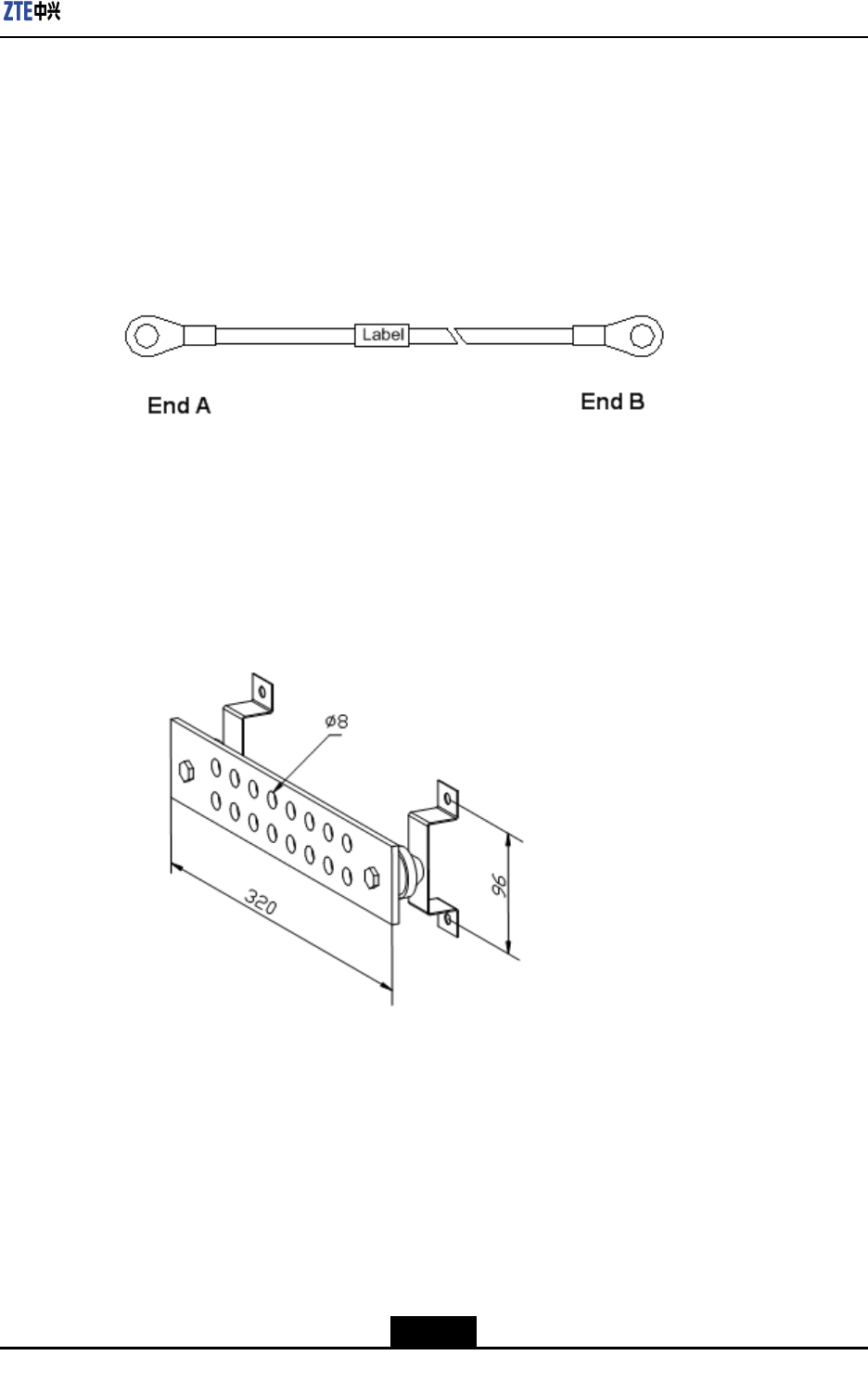
ThegroundingcableofZXSDRR8882L268ismadeupofstrandsofame-retardantwire.
Thecrosssectionalareaofgroundingcableis25mm2.Copperlugsarecrimpedatboth
endsofthegroundingcable,asshowninFigure4-35.
Figure4-35StructureofGroundingCable
Steps
1.CoverandxacopperlugontheagroundingboltoftheZXSDRR8882L268cabinet.
2.Connecttheothercopperlugtotheearth-networkingcopperbarandxitwithbolts,
asshowninFigure4-36.
Figure4-36GroundingCopperBar
3.Attachthelabelonthegroundingcable.
4.Measurethegroundingresistanceandmakesureitislessthan5ohms.
–EndofSteps–
4.6.5InstallingFiberBetweeneBBUandeRRU
Prerequisite
TheZXSDRR8882L268unithasbeeninstalledandsecurelyfastened.
4-29
SJ-20110104194923-001|2011-01-19(R1.0)ZTEProprietaryandCondential
ZXSDRR8882L268UserManual
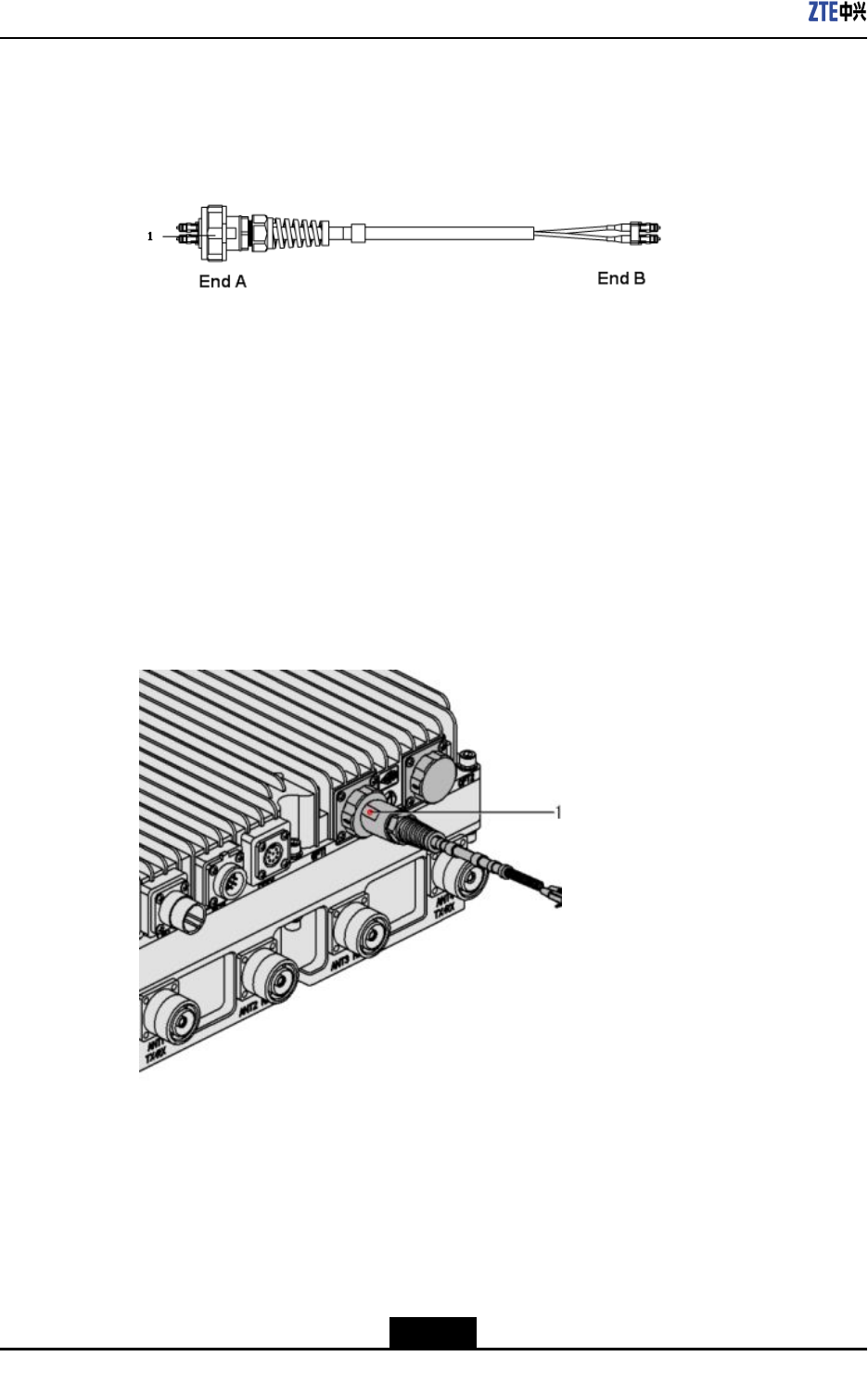
Context
Figure4-37showsberconnectionbetweenZXSDRR8882L268andeBBU.
Figure4-37FiberthatconnectsZXSDRR8882L268andeBBU
1.Outdoorsealingcomponent
WhileconnectingaeBBUtoZXSDRR8882L268,makesurethatthebasebandRFber
interface(LC1/2)ofZXSDRR8882L268isconnectedtotheopticalinterfaceconnectorof
eBBU.
Steps
1.Attachlabelsatbothendsoftheber.
2.AdjustthesideofendAwiththecolormarkandinsertberinterface,andscrewdown
thenuts,asshowninFigure4-38.
Figure4-38InstallingFibers
1.Colormark
3.ConnectendAofthebertothebaseband-RFberinterface(LC1/2)ofZXSDRR8882
L268.ConnectendBoftheber,whichisaDLCconnector,totheeBBUoptical
connector.
4.ScrewdowntheoutdoorsealcomponentatendAforwaterproof.
–EndofSteps–
4-30
SJ-20110104194923-001|2011-01-19(R1.0)ZTEProprietaryandCondential
Chapter4ProductInstallation
4.6.6InstallingFibersBetweeneRRUs
Prerequisite
TheZXSDRR8882L268cabinetforcascadehasbeeninstalledandsecurelyfastened.
Context
Figure4-39showsthestructureofcascadebersbetweenZXSDRR8882L268s.
Figure4-39CascadeberbetweenZXSDRR8882L268s
1.Outdoorsealingcomponent
OninterconnectionbetweenZXSDRR8882L268s,connecttwobaseband-RFberinter-
faces(OPT1/2)fortwoZXSDRR8882L268sbyusingaber.
Steps
1.Attachlabelsatbothendsoftheber.
2.Maketheequipmentandthesidewithcolormarkfacetoyou.Inserttheberconnector
intoopticalinterfaceandscrewdownthenuts,asshowninFigure4-40.
Figure4-40InstallingFibers
1.Colormark
4-31
SJ-20110104194923-001|2011-01-19(R1.0)ZTEProprietaryandCondential
ZXSDRR8882L268UserManual
3.ConnectendAofthebertobaseband-RFberinterface(OPT1/2)ofZXSDRR8882
L268.ConnectendBofthebertobaseband-RFinterface(OPT1/2)oftheother
ZXSDRR8882L268.
4.Screwdowntheoutdoorsealcomponentforwaterproof.
–EndofSteps–
4.6.7InstallingEnvironmentMonitorCable
Prerequisite
TheZXSDRR8882L268cabinethasbeeninstalledandsecurelyfastened.
Context
Theenvironmentmonitorcableprovidesa485interface,usedforZXSDRR8882L268
environmentmonitor.Italsoprovidesfourextensionaccessesforexternaldrycontact
monitor.
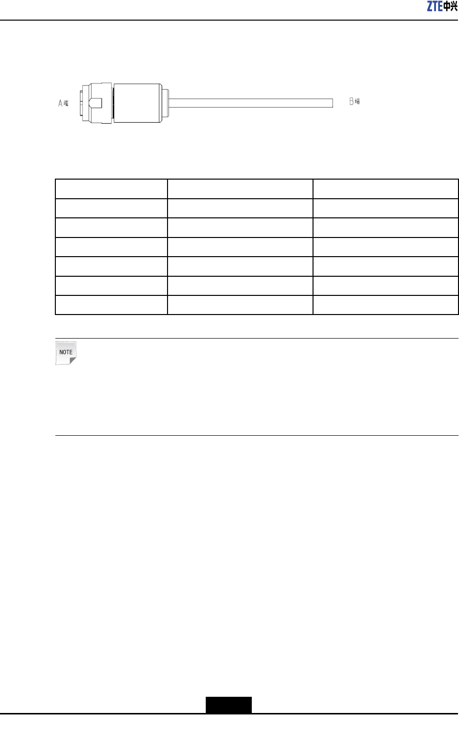
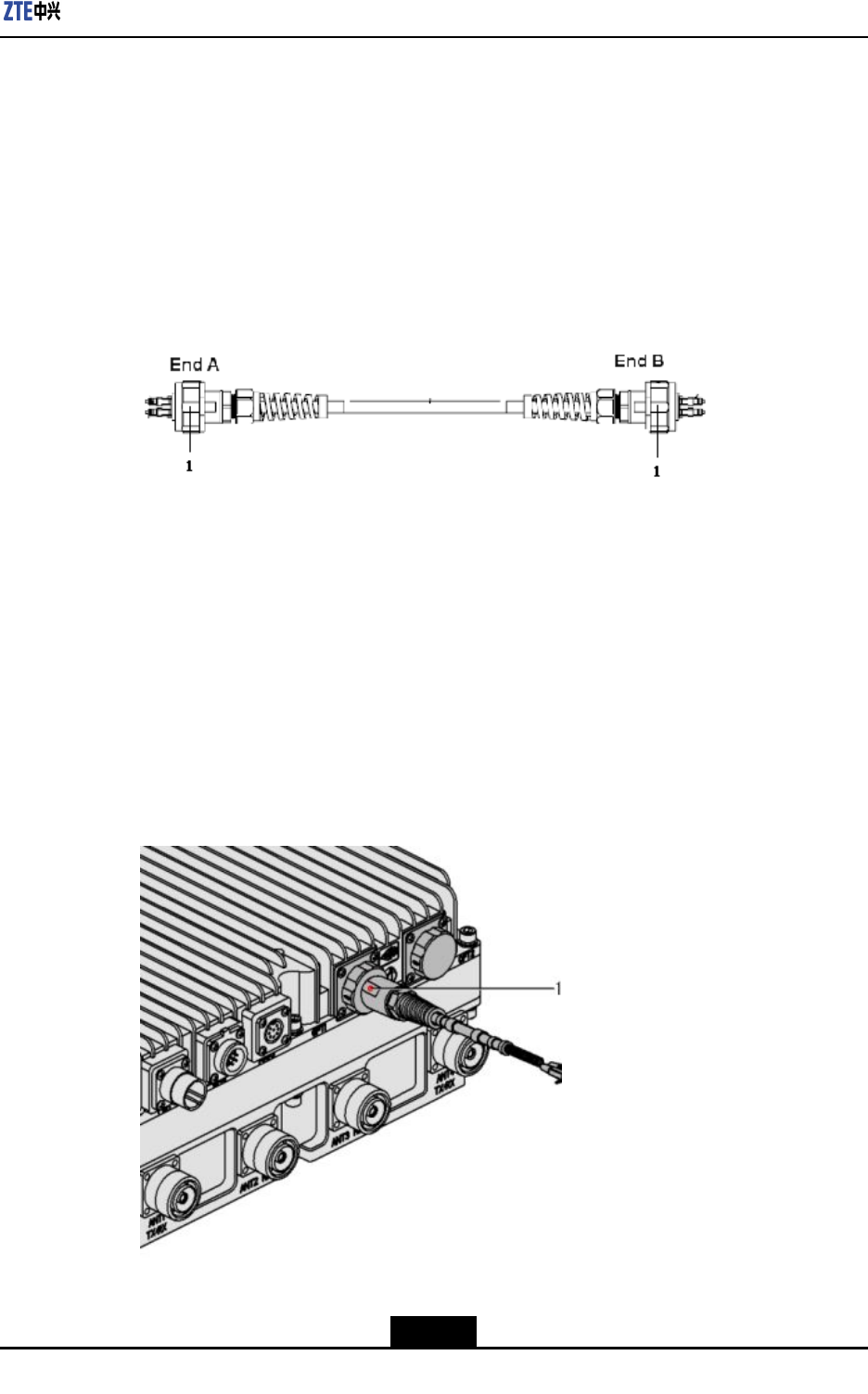
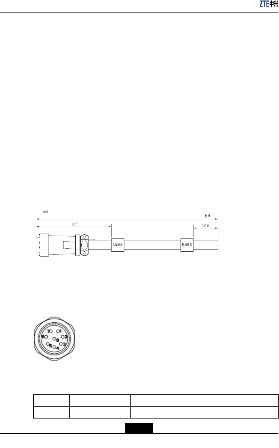
EndAiscircular8-coreplugandendBismadedependingonactualconditions.Thetotal
lengthis3m.Figure4-41showsthestructureofenvironmentmonitorcable.
Figure4-41EnvironmentMonitorCable
Theconnector,connectingtheenvironmentmonitoringcabletoZXSDRR8882L268,is
8-corestraightweldedconnector(pin)mountedonpanel.Theconnectorappearanceis
showninFigure4-42.
Figure4-42AppearanceofEnvironmentMonitorCable
ThecableconnectorpinsandconnectionareshowninT able4-5.
Table4-5CablePinDescription
PinCorecolorSignalDescription
PIN1BrownDrycontactinput,positivepolarity
4-32
SJ-20110104194923-001|2011-01-19(R1.0)ZTEProprietaryandCondential

Chapter4ProductInstallation
PinCorecolorSignalDescription
PIN2YellowDrycontactinput,negativepolarity
PIN3BlueDrycontactinput,positivepolarity
PIN4WhiteDrycontactinput,negativepolarity
PIN5GreenPositiveRS485bussignal
PIN6GreyNegativeRS485bussignal
PIN7RedPositiveRS485bussignal
PIN8BlackNegativeRS485bussignal
Note:
ConnecttherstdrycontactofeRRUtooutdoorDClightningprotectionbox.
Steps
1.ConnectendAofenvironmentmonitorcabletoenvironmentmonitorinterfaceof
ZXSDRR8882L268cabinet.
2.ConnectendBofenvironmentmonitorcabletoexternalmonitorpartordrycontact.
3.AttachthelabelsonendB.
–EndofSteps–
4.6.8InstallingAISGControlCable
Context
AISGisusedtocontroltheelectrical-adjustmentantenna.
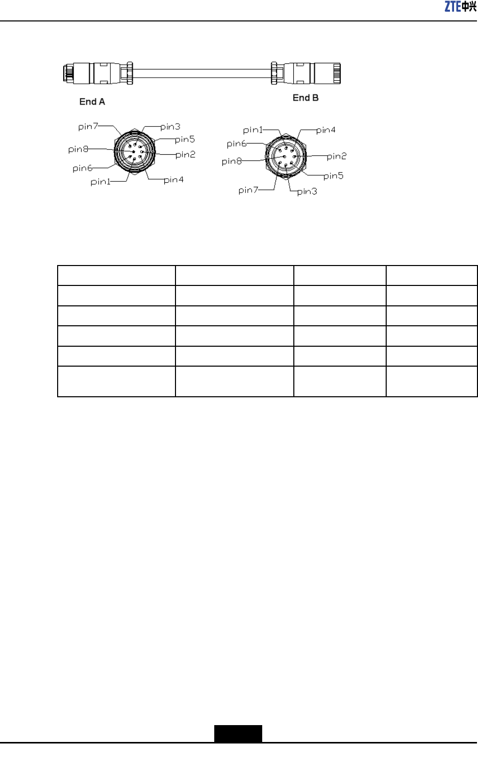
Figure4-43showsthestructureofAISGcontrolcable.
4-33
SJ-20110104194923-001|2011-01-19(R1.0)ZTEProprietaryandCondential
ZXSDRR8882L268UserManual
Figure4-43StructureofAISGControlCable
Table4-6describesthemeaningofsequencenumberofAISGcontrolcable.
Table4-6MeaningofSequenceNumberofAISGControlCable
PinsatendAPinsatEndBNameMeaning
PIN3PIN1RS485BRS485-
PIN5PIN2RS485ARS485+
PIN6PIN3,PIN4DCDCoutput
PIN7PIN5,PIN6DCRTNDCRTN
PIN1,PIN2,PIN4,PIN8NCNull
Steps
1.ConnectendAtoZXSDRR8882L268debugginginterface(AISG)andscrewdown
thebolt.
2.ConnectendBtothecontrolinterfaceofelectricaladjustmentantennaandscrew
downthebolt.
–EndofSteps–
4.6.9InstallingAntennaFeederJumper
Context
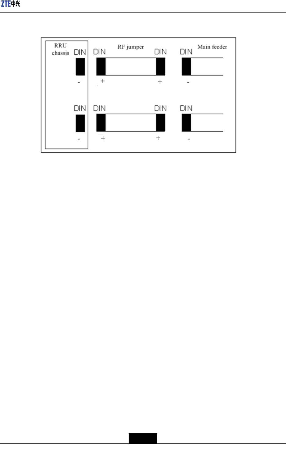
RFjumperisacablesegmentthatconnectsmainfeederandantennafeederinterfaceof
ZXSDRR8882L268cabinet.TheRFjumperisinstalledafterthemainfeederisinstalled
completely.
TheRFjumperusuallyusesthenished1/2″jumperwith2mlength.Thejumpercanbe
customizeddependingonactualconditions.
Figure4-44showsinstallationpositionsofRFjumper.
4-34
SJ-20110104194923-001|2011-01-19(R1.0)ZTEProprietaryandCondential
Chapter4ProductInstallation
Figure4-44InstallationPositionofRFJumper
Steps
1.ConnectDINconnector(male)ofRFjumperwithDINconnector(female)ofmain
feeder.
2.ConnectDINconnector(male)ofRFjumperwithRFantennainterfaceofcabinet.
3.Sealtheconnectorstomakethemwaterproof.
–EndofSteps–
4-35
SJ-20110104194923-001|2011-01-19(R1.0)ZTEProprietaryandCondential

ZXSDRR8882L268UserManual
Thispageintentionallyleftblank.
4-36
SJ-20110104194923-001|2011-01-19(R1.0)ZTEProprietaryandCondential

Figures
Figure2-1ZTEDistributedeNodeBSolution.............................................................2-2
Figure2-2ProductLocation......................................................................................2-3
Figure2-3ProductOverallAppearance....................................................................2-5
Figure2-4StarNetworkingMode.............................................................................2-6
Figure2-5OperateandMaintainSystemRemotely..................................................2-6
Figure2-6OperateandMaintainSystemLocally......................................................2-7
Figure2-7ProductExternalInterfacesandGroundingTerminal................................2-7
Figure2-8LMTInterface..........................................................................................2-8
Figure2-9ProductIndicators....................................................................................2-9
Figure4-1PackingofZXSDRR8882L268...............................................................4-7
Figure4-2UnpackingandInspectionFlow...............................................................4-8
Figure4-3InstallationFlow.....................................................................................4-10
Figure4-4TemplateHolePosition..........................................................................4-11
Figure4-5InstallingWall-mountingComponents...................................................4-11
Figure4-6Wall-mountingComponentsOnWall......................................................4-12
Figure4-7HungDeviceOnTheWall-mountingComponents.................................4-12
Figure4-8FasteningZXSDRR8882L268..............................................................4-13
Figure4-9ZXSDRR8882L268IsInstalledOnWall...............................................4-13
Figure4-10FixingWall-mountingcomponentsandPoleClips................................4-14
Figure4-11FixingWall-mountingComponentsandPoleClipsOnPole..................4-14
Figure4-12HungtheDeviceOntheWall-mountingComponents...........................4-15
Figure4-13FixingTheDeviceOnTheWall-mountingComponents.......................4-15
Figure4-14ZXSDRR8882L268IsInstalledOnPole.............................................4-16
Figure4-15FixingWall-mountingcomponentsandPoleClips................................4-16
Figure4-16FixingWall-mountingComponentsandPoleClipsOnPole..................4-17
Figure4-17HungtheDevicesOntheWall-mountingComponents.........................4-17
Figure4-18FixingTheDevicesOnTheWall-mountingComponents......................4-18
Figure4-19ZXSDRR8882L268areInstalledOnPole...........................................4-18
Figure4-20FixingWall-mountingcomponentsandPoleClips................................4-19
Figure4-21FixingWall-mountingComponentsandPoleClipsOnPole..................4-19
Figure4-22FixingTheThirdWall-mountingComponents.......................................4-20
Figure4-23HungtheDevicesOntheWall-mountingComponents.........................4-20
I
SJ-20110104194923-001|2011-01-19(R1.0)ZTEProprietaryandCondential

ZXSDRR8882L268UserManual
Figure4-24ZXSDRR8882L268AreInstalledOnPole..........................................4-21
Figure4-25InstallingTheVerticalShaftAndTheBottomPlate..............................4-21
Figure4-26FastenTheVerticalShaftAndTheCoverPlate..................................4-22
Figure4-27InstallingTheSlantedRack..................................................................4-22
Figure4-28MarkingTheDrillingHolesPosiotion....................................................4-23
Figure4-29InstallingTheExpansionBolt...............................................................4-23
Figure4-30InstallingTheGantryOnTheConcreteFloor......................................4-24
Figure4-31InstallingTheGantryOnTheWoodenFloor........................................4-24
Figure4-32ZXSDRR8882L268IsInstalledOnGantry.........................................4-25
Figure4-33ExternalCableInstallationFlow...........................................................4-27
Figure4-34StructureofPowerCable.....................................................................4-28
Figure4-35StructureofGroundingCable...............................................................4-29
Figure4-36GroundingCopperBar.........................................................................4-29
Figure4-37FiberthatconnectsZXSDRR8882L268andeBBU.............................4-30
Figure4-38InstallingFibers....................................................................................4-30
Figure4-39CascadeberbetweenZXSDRR8882L268s......................................4-31
Figure4-40InstallingFibers....................................................................................4-31
Figure4-41EnvironmentMonitorCable..................................................................4-32
Figure4-42AppearanceofEnvironmentMonitorCable..........................................4-32
Figure4-43StructureofAISGControlCable..........................................................4-34
Figure4-44InstallationPositionofRFJumper........................................................4-35
II
SJ-20110104194923-001|2011-01-19(R1.0)ZTEProprietaryandCondential

Tables
Table2-1ProductExternalInterfacesDescription.....................................................2-8
Table2-2ProductIndicatorDescription.....................................................................2-9
Table3-1CPRIInterfaceIndex.................................................................................3-2
Table3-2ReceiverSensitivity...................................................................................3-2
Table3-3FRCParametersforReferenceSensitivityandIn-channel
Selectivity................................................................................................3-3
Table4-1SafetySymbolsandTheirDescriptions.....................................................4-1
Table4-2InstallationAccessoriesDescription...........................................................4-9
Table4-3ConnectionofZXSDRR8882L268ExternalCables...............................4-25
Table4-4ColorandDenitionofInnerCoreofthePowerCable.............................4-28
Table4-5CablePinDescription..............................................................................4-32
Table4-6MeaningofSequenceNumberofAISGControlCable.............................4-34
III
SJ-20110104194923-001|2011-01-19(R1.0)ZTEProprietaryandCondential

Tables
Thispageintentionallyleftblank.
IV
SJ-20110104194923-001|2011-01-19(R1.0)ZTEProprietaryandCondential

Glossary
AISG
-AntennaInterfaceStandardsGroup
CPRI
-CommonPublicRadioInterface
CRC
-CyclicRedundancyCheck
LTE
-LongTermEvolution
MTBF
-MeanTimeBetweenFailures
MTTR
-MeanTimeToRepair
QAM
-QuadratureAmplitudeModulation
QPSK
-QuadraturePhaseShiftKeying
RF
-RadioFrequency
SDR
-SoftwareDenedRadio
eBBU
-evolvedBaseBandUnit
eNodeB
-EvolvedNodeB
eRRU
-evolvedRemoteRadioUnit
V
SJ-20110104194923-001|2011-01-19(R1.0)ZTEProprietaryandCondential