User Manual

ZXSDRR8978
TDD8PathRemoteRadioUnit
UserManual
Version:V5.10
ZTECORPORATION
No.55,Hi-techRoadSouth,ShenZhen,P .R.China
Postcode:518057
Tel:+86-755-26771900
Fax:+86-755-26770801
URL:http://support.zte.com.cn
E-mail:800@zte.com.cn

LEGALINFORMATION
Copyright©2017ZTECORPORATION.
Thecontentsofthisdocumentareprotectedbycopyrightlawsandinternationaltreaties.Anyreproductionor
distributionofthisdocumentoranyportionofthisdocument,inanyformbyanymeans,withoutthepriorwritten
consentofZTECORPORATIONisprohibited.Additionally,thecontentsofthisdocumentareprotectedby
contractualcondentialityobligations.
Allcompany,brandandproductnamesaretradeorservicemarks,orregisteredtradeorservicemarks,ofZTE
CORPORATIONoroftheirrespectiveowners.
Thisdocumentisprovided“asis”,andallexpress,implied,orstatutorywarranties,representationsorconditions
aredisclaimed,includingwithoutlimitationanyimpliedwarrantyofmerchantability,tnessforaparticularpurpose,
titleornon-infringement.ZTECORPORATIONanditslicensorsshallnotbeliablefordamagesresultingfromthe
useoforrelianceontheinformationcontainedherein.
ZTECORPORATIONoritslicensorsmayhavecurrentorpendingintellectualpropertyrightsorapplications
coveringthesubjectmatterofthisdocument.ExceptasexpresslyprovidedinanywrittenlicensebetweenZTE
CORPORATIONanditslicensee,theuserofthisdocumentshallnotacquireanylicensetothesubjectmatter
herein.
ZTECORPORATIONreservestherighttoupgradeormaketechnicalchangetothisproductwithoutfurthernotice.
UsersmayvisittheZTEtechnicalsupportwebsitehttp://support.zte.com.cntoinquireforrelatedinformation.
TheultimaterighttointerpretthisproductresidesinZTECORPORATION.
RevisionHistory
RevisionVersionRevisionDateRevisionReason
R1.22016–08–17AddedS2600L
R1.12014-10-30AddedS2600M
R1.02014-08-06Firstedition
SerialNumber:SJ-20141113151137-001
PublishingDate:2016-08-17(R1.2)
SJ-20141113151137-001|2016-08-17(R1.2)ZTEProprietaryandCondential

Contents
AboutThisManual.........................................................................................I
Chapter1FCCRelatedStatements..........................................................1-1
Chapter2ProductOverview.....................................................................2-1
2.1ProductPositioning............................................................................................2-1
2.2ProductFeatures................................................................................................2-2
2.3ExternalView.....................................................................................................2-2
2.4ProductSpecications........................................................................................2-3
2.4.1ZXSDRR8978S2300...............................................................................2-3
2.4.2ZXSDRR8978S2600M............................................................................2-4
2.4.3ZXSDRR8978S2600L.............................................................................2-4
2.5ExternalInterfaces.............................................................................................2-5
2.6InstallationModes..............................................................................................2-6
2.7TypicalNetworkingApplications..........................................................................2-6
Chapter3ProductComposition...............................................................3-1
3.1SystemStructure................................................................................................3-1
3.2Composition.......................................................................................................3-2
3.3LEDIndicators...................................................................................................3-3
3.4PhysicalInterfacesandCables...........................................................................3-5
3.4.1ProtectiveGroundingCable......................................................................3-5
3.4.2DCPowerInputCable..............................................................................3-6
3.4.3LMT/TSTInterfaceCable..........................................................................3-9
3.4.4OpticalFiber..........................................................................................3-10
3.4.5AntennaFeederInterfaceCable...............................................................3-11
3.4.6CAL/AISGInterfaceCable......................................................................3-13
3.4.7EAM/RGPSInterfaceCable....................................................................3-14
3.5ExternalCableConnection...............................................................................3-14
3.6SoftwareComposition.......................................................................................3-15
Chapter4OperationandMaintenance.....................................................4-1
4.1T echnicalSupport...............................................................................................4-1
4.2FaultLocation....................................................................................................4-2
4.3EquipmentMaintenance.....................................................................................4-3
4.4PowerOn..........................................................................................................4-4
4.5PowerOff..........................................................................................................4-5
I
SJ-20141113151137-001|2016-08-17(R1.2)ZTEProprietaryandCondential

4.6PartsReplacement.............................................................................................4-6
4.6.1ReplacingtheZXSDRR8978....................................................................4-6
4.6.2ReplacingtheOpticalModule....................................................................4-7
4.6.3ReplacingtheRFCable............................................................................4-8
Chapter5AccessoryDevices...................................................................5-1
5.1JunctionBox......................................................................................................5-1
5.2ACPowerLighteningProtectionBox...................................................................5-3
5.3ReplacingtheACPowerLightingProtectionBox..................................................5-6
Chapter6TechnicalSpecications..........................................................6-1
6.1PhysicalSpecications.......................................................................................6-1
6.2PerformanceIndexes.........................................................................................6-1
6.3PowerConsumption...........................................................................................6-2
6.4ReliabilityIndexes..............................................................................................6-2
6.5GroundingRequirement......................................................................................6-3
6.6LighteningandSurgeProtection.........................................................................6-3
Chapter7EnvironmentRequirements.....................................................7-1
7.1PowerSupplyRequirements...............................................................................7-1
7.2OperatingEnvironment.......................................................................................7-1
7.3StorageEnvironment..........................................................................................7-2
Figures.............................................................................................................I
Tables............................................................................................................III
Glossary.........................................................................................................V
II
SJ-20141113151137-001|2016-08-17(R1.2)ZTEProprietaryandCondential
AboutThisManual
Purpose
Thismanualdescribesthesoftwareandhardwarestructures,interfacesandcables,
functions,features,technicalspecications,installationmodes,networking,and
maintenancemethodsoftheZXSDRR8978.
IntendedAudience
Thismanualisintendedfor:
lBasestationinstallationengineers
lBasestationcommissioningengineers
lBasestationmaintenanceengineers
WhatIsinThisManual
Thismanualcontainsthefollowingchapters.
Chapter1,FCCRelated
Statements
DescribesthestatementsrelatedtoFCCrule.
Chapter2,ProductOverviewDescribestheexternalview,interfaces,functions,features,and
typicalnetworkapplicationsoftheZXSDRR8978.
Chapter3,ProductCompositionDescribesthesystemstructure,hardwarecomposition,and
softwarecompositionoftheZXSDRR8978.
Chapter4,Operationand
Maintenance
Providesthetechnicalsupportcontactinformation,power-onand
power-offow,andcomponentreplacementmethods.
Chapter5,AccessoryDevicesDescribestheaccessorydevices,includingjunctionbox,andAC
powerlighteningprotectionbox,andthereplacementmethods.
Chapter6,Technical
Specications
ProvidesthetechnicalspecicationsoftheZXSDRR8978.
Chapter7,Environment
Requirements
DescribestheenvironmentrequirementsoftheZXSDRR8978.
Conventions
Thismanualusesthefollowingconventions.
Danger:indicatesanimminentlyhazardoussituation.Failuretocomplycanresultin
deathorseriousinjury,equipmentdamage,orsitebreakdown.
Warning:indicatesapotentiallyhazardoussituation.Failuretocomplycanresultin
seriousinjury,equipmentdamage,orinterruptionofmajorservices.
I
SJ-20141113151137-001|2016-08-17(R1.2)ZTEProprietaryandCondential
Caution:indicatesapotentiallyhazardoussituation.Failuretocomplycanresultin
moderateinjury,equipmentdamage,orinterruptionofminorservices.
Note:providesadditionalinformationaboutatopic.
II
SJ-20141113151137-001|2016-08-17(R1.2)ZTEProprietaryandCondential
Chapter1
FCCRelatedStatements
Warning!
Changesormodicationstothisunitnotexpresslyapprovedbythepartyresponsiblefor
compliancecouldvoidtheuser’sauthoritytooperatetheequipment.
ThisequipmenthasbeentestedandfoundtocomplywiththelimitsforaClassAdigital
device,pursuanttoPart15oftheFCCRules.Theselimitsaredesignedtoprovide
reasonableprotectionagainstharmfulinterferencewhentheequipmentisoperatedin
acommercialenvironment.Thisequipmentgenerates,uses,andcanradiateradio
frequencyenergyand,ifnotinstalledandusedinaccordancewiththeinstructionmanual,
maycauseharmfulinterferencetoradiocommunications.Operationofthisequipment
inaresidentialareaislikelytocauseharmfulinterferenceinwhichcasetheuserwillbe
requiredtocorrecttheinterferenceathisownexpense.
Operationofthisequipmentinaresidentialareaislikelytocauseharmfulinterferencein
whichcasetheuserwillberequiredtocorrecttheinterferenceathisownexpense.
ThisequipmentcomplieswithFCCradiationexposurelimitssetforthforanuncontrolled
environment.Thisequipmentshouldbeinstalledandoperatedwithminimumdistance
10.2mbetweentheradiator&yourbody.
1-1
SJ-20141113151137-001|2016-08-17(R1.2)ZTEProprietaryandCondential

ZXSDRR8978UserManual
Thispageintentionallyleftblank.
1-2
SJ-20141113151137-001|2016-08-17(R1.2)ZTEProprietaryandCondential
Chapter2
ProductOverview
TableofContents
ProductPositioning....................................................................................................2-1
ProductFeatures........................................................................................................2-2
ExternalView.............................................................................................................2-2
ProductSpecications................................................................................................2-3
ExternalInterfaces.....................................................................................................2-5
InstallationModes......................................................................................................2-6
TypicalNetworkingApplications.................................................................................2-6
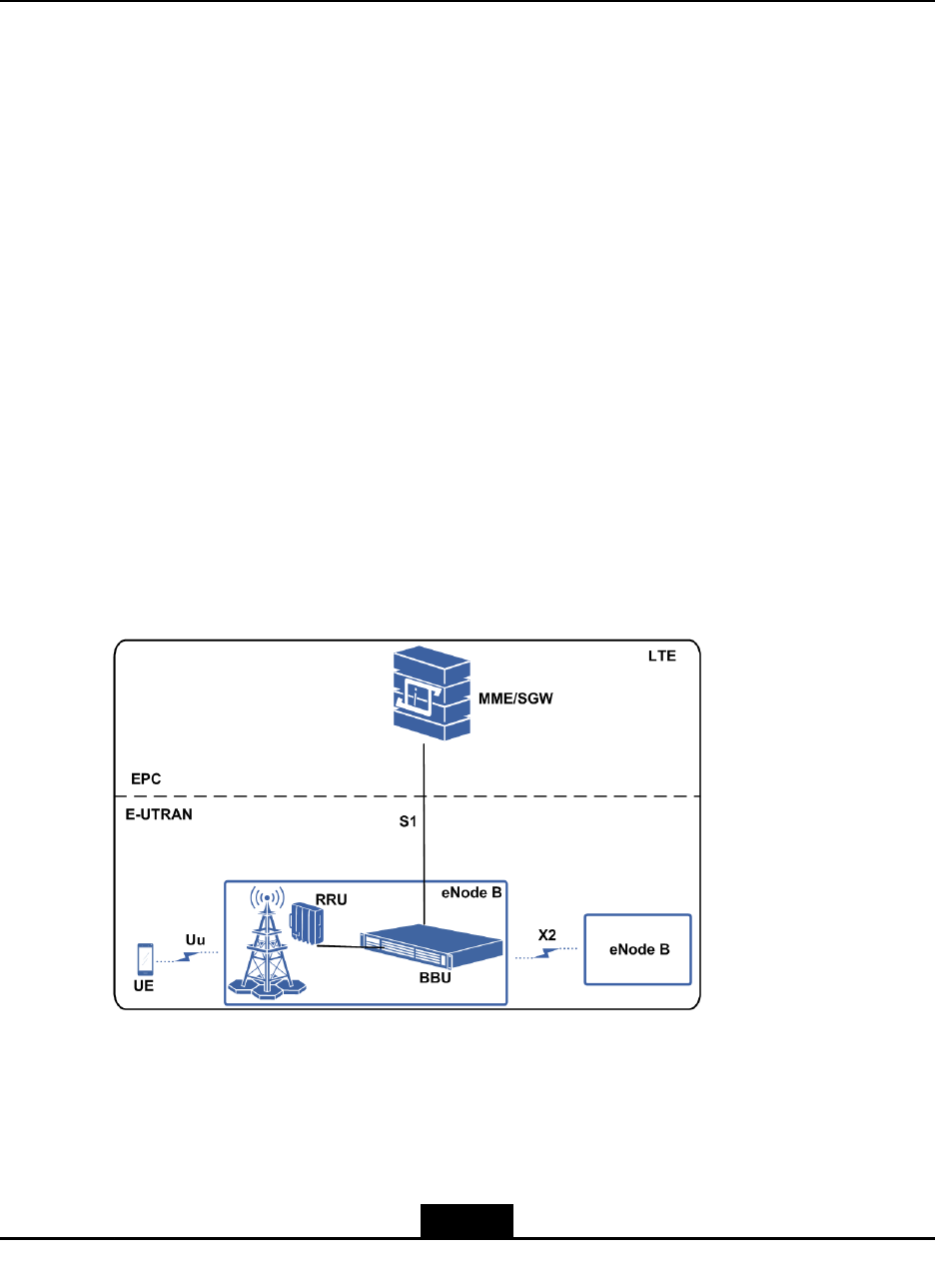
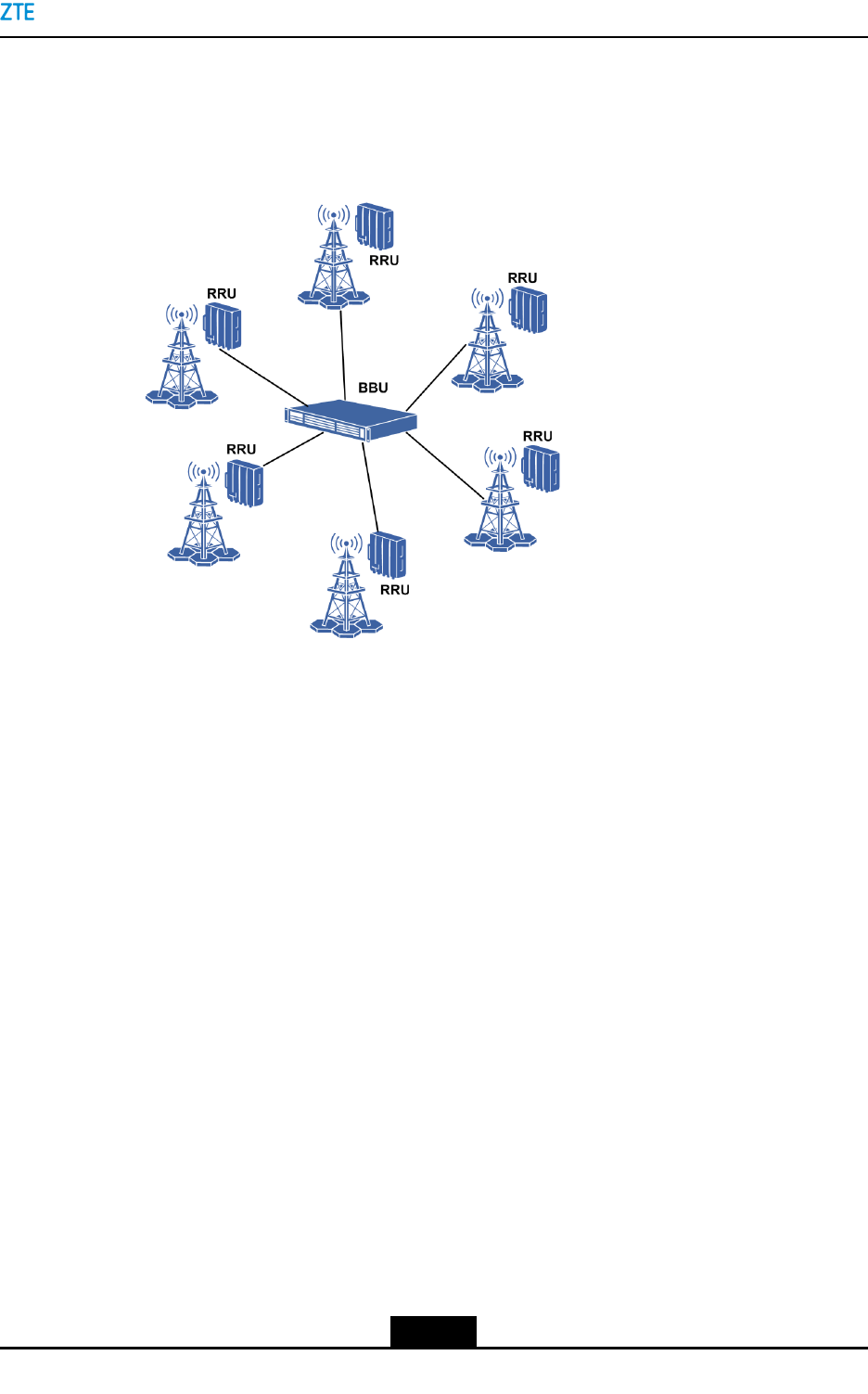
2.1ProductPositioning
TheZXSDRR8978isaneight-pathTD-LTERRUwithhighpower.ItoperateswithaBBU
tocovernewoutdoorsites.
TheZXSDRR8978workswithaBBUtocomposeacompleteeNodeBandimplementthe
functionssuchasradiotransmissioninthecoverageareaandradiochannelcontrol.
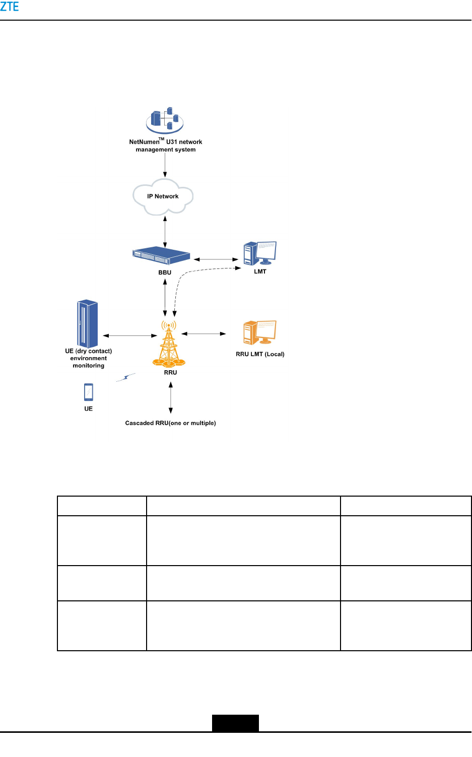
Figure2-1illustratesthepositionoftheZXSDRR8978inaLTEnetwork.
Figure2-1PositionoftheRRUinaNetwork
2-1
SJ-20141113151137-001|2016-08-17(R1.2)ZTEProprietaryandCondential

ZXSDRR8978UserManual
2.2ProductFeatures
UniedPlatform
TheZXSDRR8978isdevelopedbasedontheuniedSDRplatform,whichsupports
smoothevolutiontonewtechnologiesinthefuture,andprotectstheoperators'investment
inmaximum.
Energyconservationandenvironmentalprotection
lDesignedwithhigh-efciencypowerampliertechnologies:CrestFactorReduction
(CFR),DigitalPre-Distortion(DPD)andDohertytoreduceequipment'spower
consumption.
lUsespassiveheatdissipationwithoutelectricalnoise,whichcansave35%power
consumptioncomparedwiththetraditionalairconditionertoeffectivelyreducethe
operators'powerconsumptioncost.
lSupportstheenergy-savingtechnologiessuchasslot-basedpowersavingand
voltageregulationpowersaving.
Multi-Carrier,MIMO,BF,andHighPerformance
lSupportsmultiplefrequencybandssuchas2.3GHz/2.6GHztosatisfythe
requirementsofvariousoperators.
lSupportsexiblecongurationofuptoTD-LTE4x20MHzmulti-carrierstofullyand
exiblyutilizetheoperators'spectrum.
HighOutputPower
Upto160W(8x20W)outputpowerisprovidedtosatisfythepowerrequirementsforhigh
capacityandlargecoverage.
10GbpsOpticalInterface
Two10GbpsCPRIopticalinterfacesareprovidedtosatisfytheTD-LTECPRIow
requirement.CPRIopticalinterfacemulti-modetransmissionissupported(the6Gbps
opticalinterfacerateisalsosupported).
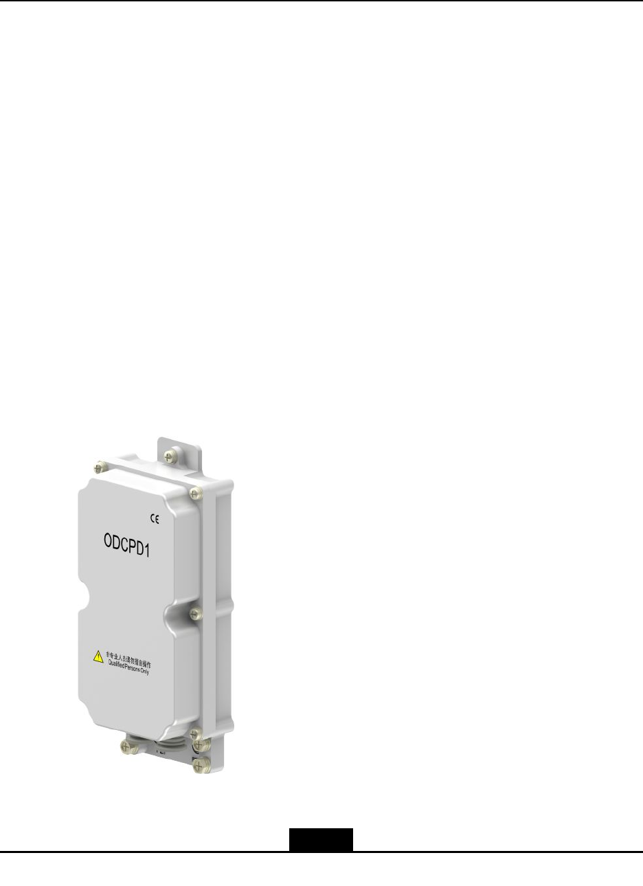
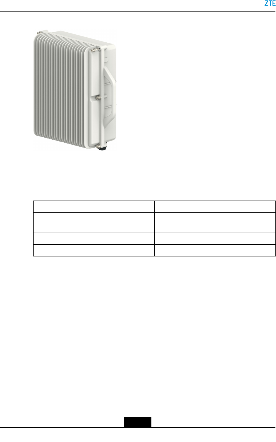
2.3ExternalView
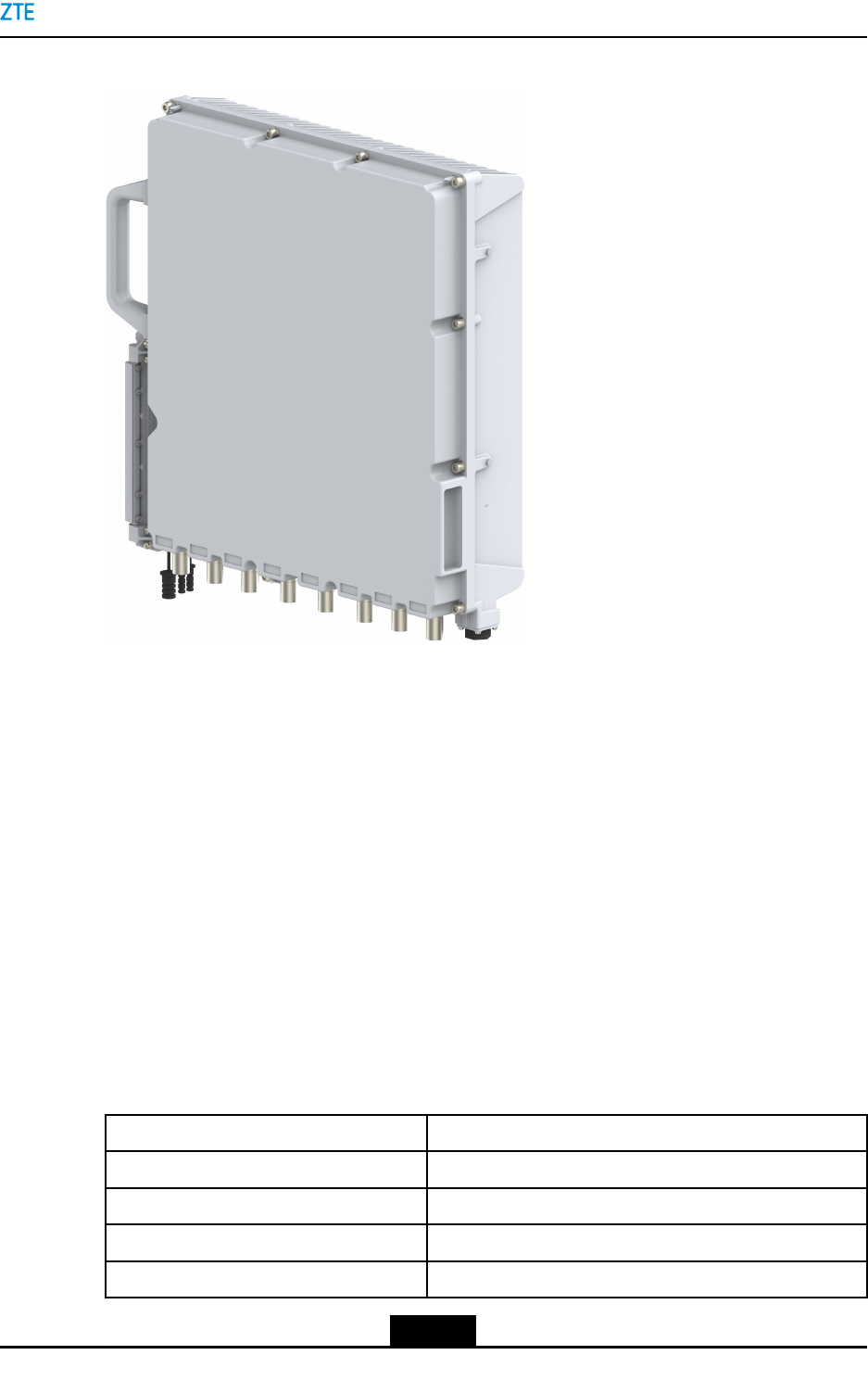
Figure2-2showstheexternalviewoftheZXSDRR8978.
2-2
SJ-20141113151137-001|2016-08-17(R1.2)ZTEProprietaryandCondential
Chapter2ProductOverview
Figure2-2ExternalView
2.4ProductSpecications
TheZXSDRR8978isaneight-channelRRUthatanbeusedfornetworkingTD-LTEmacro
cells.
Inthismanual,allthedescriptionsfortheZXSDRR8978areapplicabletothefollowing
specicationsunlessspeciallystated:
lZXSDRR8978S2300
lZXSDRR8978S2600M
lZXSDRR8978S2600L
2.4.1ZXSDRR8978S2300
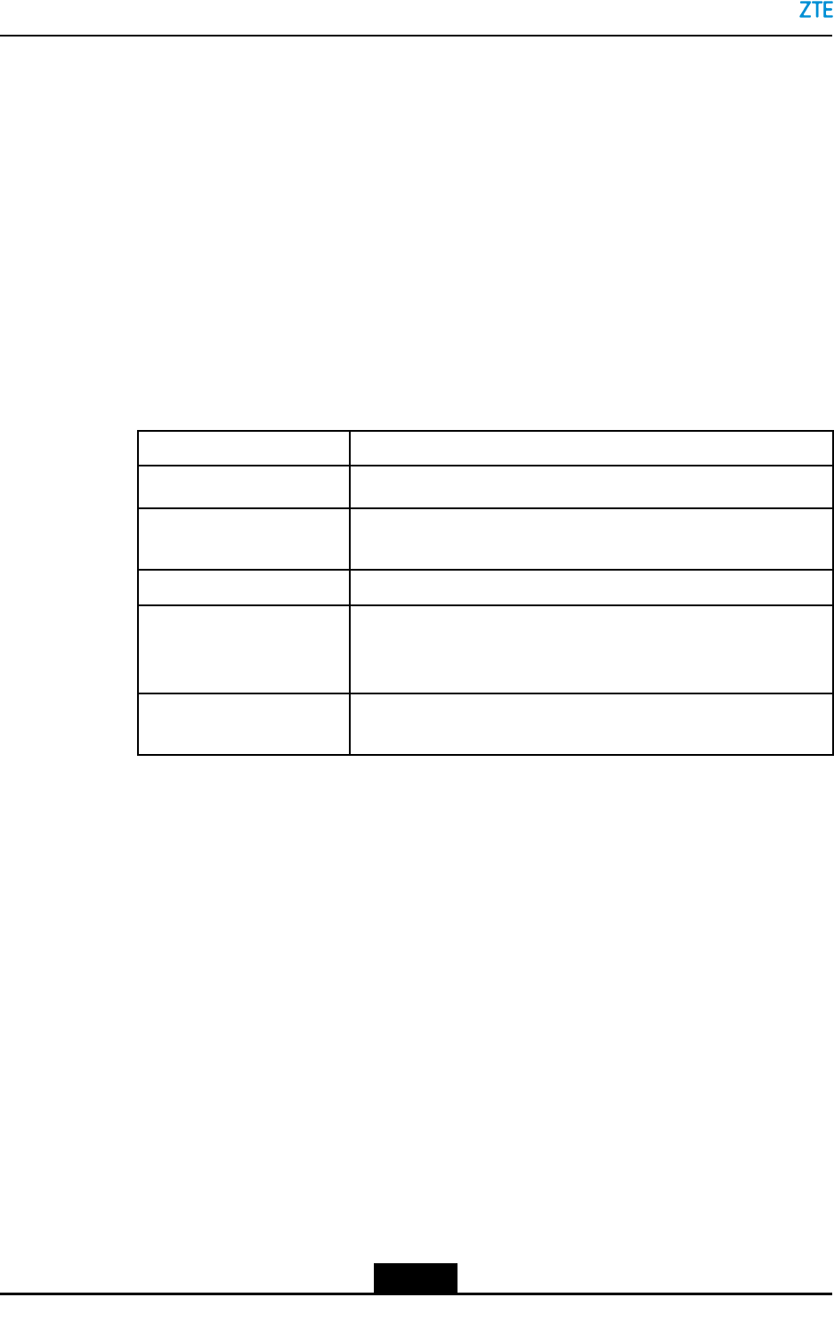
ForthekeyfeaturesoftheZXSDRR8978S2300,refertoTable2-1.
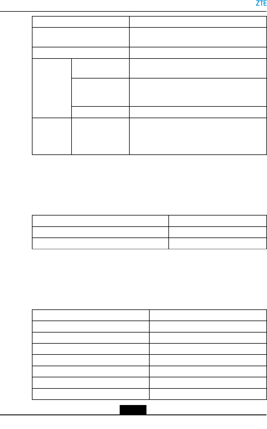
Table2-1KeyFeaturesoftheZXSDRR8978S2300
ItemDescription
RadioaccessmodeTD-LTE
Frequencyband2300MHz~2400MHz
AntennaSupports4×4MIMOdualTRXchannels.
MaximumnumberofcarriersTD-LTE:4×20MHz
2-3
SJ-20141113151137-001|2016-08-17(R1.2)ZTEProprietaryandCondential
ZXSDRR8978UserManual
ItemDescription
Signalbandwidth80MHz
Maximumpoweroutputineachchannel20W
PowerinputDC:-48VDC
AC:100VAC/110VAC/220VAC
2.4.2ZXSDRR8978S2600M
ForthekeyfeaturesoftheZXSDRR8978S2600M,refertoT able2-2.
Table2-2KeyFeaturesoftheZXSDRR8978S2600M
ItemDescription
RadioaccessmodeTD-LTE
Frequencyband2496MHz~2690MHz
AntennaSmartAntenna
RET
8–pathtransceivingchannels
MaximumnumberofcarriersTD-LTE:4x20MHz2x20MHz
Signalbandwidth100MHz
Maximumpoweroutputineachchannel20W
Powerinput-48VDC
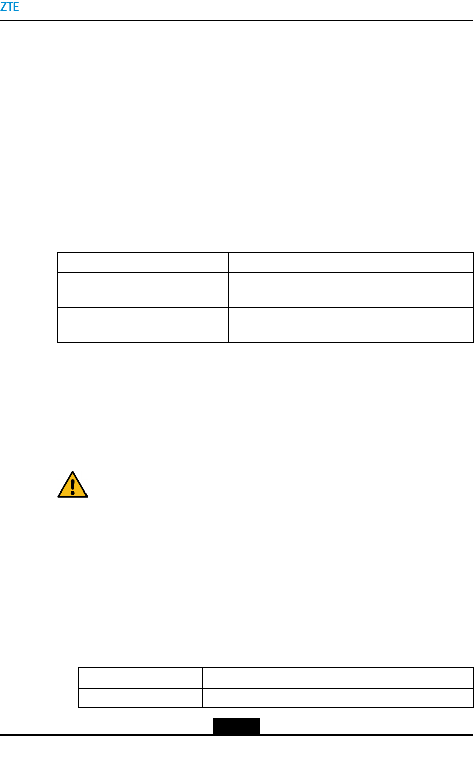
2.4.3ZXSDRR8978S2600L
ForthekeyfeaturesoftheZXSDRR8978S2600L,refertoT able2-3.
Table2-3KeyFeaturesoftheZXSDRR8978S2600L
ItemDescription
RadioaccessmodeTD-LTE
Frequencyband2575MHz~2635MHz
AntennaSmartAntenna
RET
8–pathtransceivingchannels
MaximumnumberofcarriersTD-LTE:3x20MHz
Signalbandwidth60MHz
Maximumpoweroutputineachchannel20W
Powerinput-48VDC
2-4
SJ-20141113151137-001|2016-08-17(R1.2)ZTEProprietaryandCondential
Chapter2ProductOverview
2.5ExternalInterfaces
Figure2-3illustratestheexternalinterfacesoftheZXSDRR8978.
Figure2-3ExternalInterfaces
Foradescriptionoftheexternalinterfaces,refertoTable2-4.
Table2-4ExternalInterfaceDescription
ExternalDeviceDescriptionExternalInterface
BBUBBUperformsthefunctionssuchasGPS
synchronization,maincontrol,andbaseband
processing.
Logicalinterface:Irinterface
Physicalinterface:optical
berinterface
UEUEaccomplishestheUuinterfacefunctionsof
transmittingvoiceanddataservices.
Logicalinterface:Uuinterface
Physicalinterface:none
UserdeviceExternalenvironmentmonitoringdeviceLogicalinterface:not
standardized
Physicalinterface:drycontact
2-5
SJ-20141113151137-001|2016-08-17(R1.2)ZTEProprietaryandCondential
ZXSDRR8978UserManual
ExternalDeviceDescriptionExternalInterface
RRULMTOperatesandmaintainstheRRUatthelocal
end
Logicalinterface:not
standardized
Physicalinterface:Ethernet
interface
CascadeRRUUpstreamRRULogicalinterface:Irinterface
Physicalinterface:optical
berinterface
•ExternalinterfacesexcludethepowerandantennainterfaceoftheRRU.
Note:
TheLMTattheBBUsidecanoperateandmaintainmultipleRRUsundertheBBU.ZTE
NetNumen™EMSprovidesuniedoperationandmaintenanceonmultiplesites.
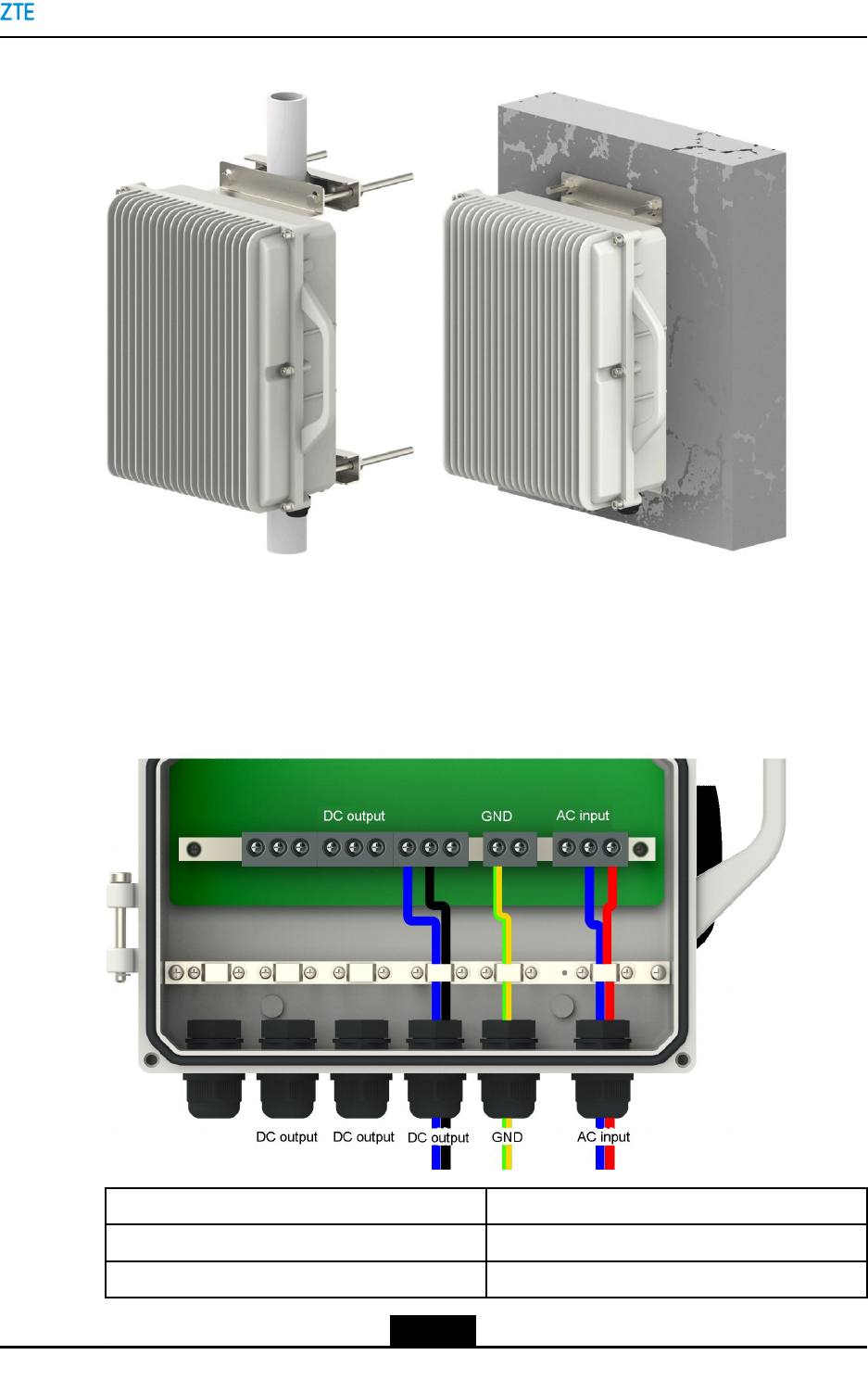
2.6InstallationModes
TheZXSDRR8978supportsthreeinstallationmodes:
lAsingleRRUmountedonapole
lTwoRRUsmountedonapole
lMountedonawall
lMountedonslotsteel
lMountedonanglesteel
2.7TypicalNetworkingApplications
TheZXSDRR8978supportsthefollowingnetworkingsolutions:
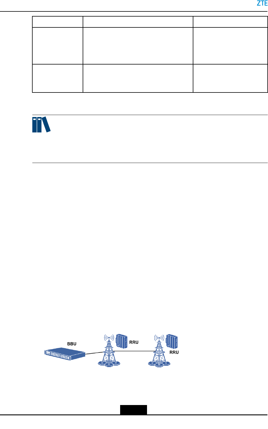
lChainnetworking
Chainnetworkingappliestostrip-shapedareaswithsparsepopulation,whereoptical
berscanbelaidconveniently.Figure2-4showsachainnetworkingsolution.
Figure2-4ChainNetworking
lStarnetworking
Inastarnetworkingsolution,aBBUisconnectedtoeachRRUandtheRRUis
theterminalequipment.Thisnetworkingtypeissimpleandeasyformaintenance
2-6
SJ-20141113151137-001|2016-08-17(R1.2)ZTEProprietaryandCondential

ZXSDRR8978UserManual
Thispageintentionallyleftblank.
2-8
SJ-20141113151137-001|2016-08-17(R1.2)ZTEProprietaryandCondential
Chapter3
ProductComposition
TableofContents
SystemStructure........................................................................................................3-1
Composition...............................................................................................................3-2
LEDIndicators............................................................................................................3-3
PhysicalInterfacesandCables..................................................................................3-5
ExternalCableConnection.......................................................................................3-14
SoftwareComposition..............................................................................................3-15
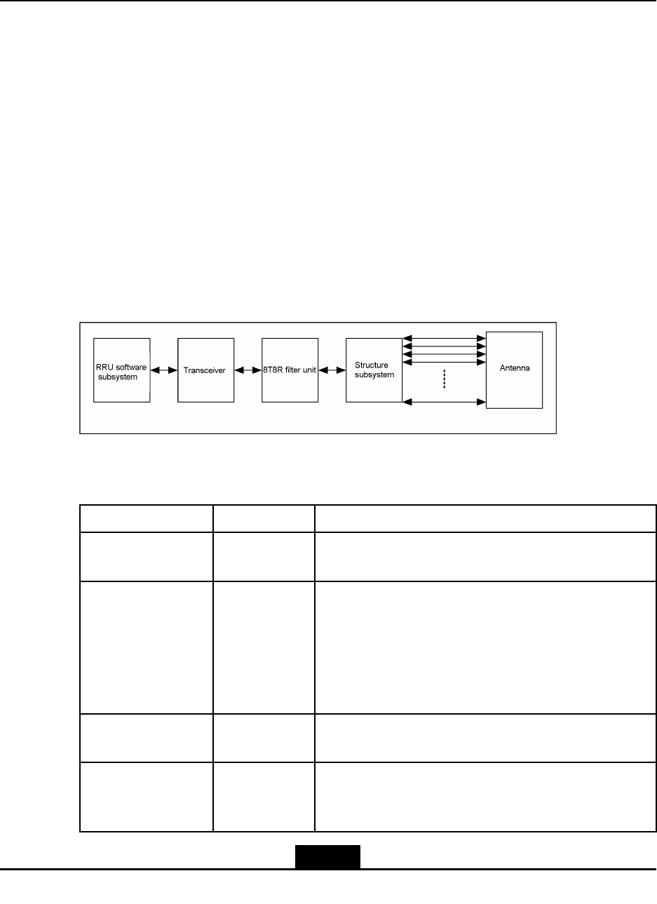
3.1SystemStructure
Figure3-1showsthesystemstructureoftheZXSDRR8978.
Figure3-1SystemStructure
Table3-1describesthesubsystemsoftheZXSDRR8978.
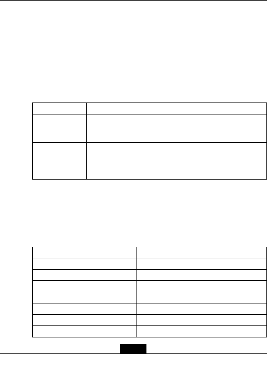
Table3-1SubsystemDescription
NameTypeFunction
RRUsoftware
subsystem
Software
subsystem
ProvidesthesystemoperatingsystemandOMfunctions
TransceiverHardware
subsystem
lPowerinterface
lOpticalinterface
lControlfunctions
lClockfunctions
lDIF
lTRX
8T8RlterunitHardware
subsystem
Eight-channellter
StructuresubsystemStructure
subsystem
Providesequipmentprotection,heatdissipation,and
installation,andmodulestructure,heatdissipation,and
installation.
3-1
SJ-20141113151137-001|2016-08-17(R1.2)ZTEProprietaryandCondential
ZXSDRR8978UserManual
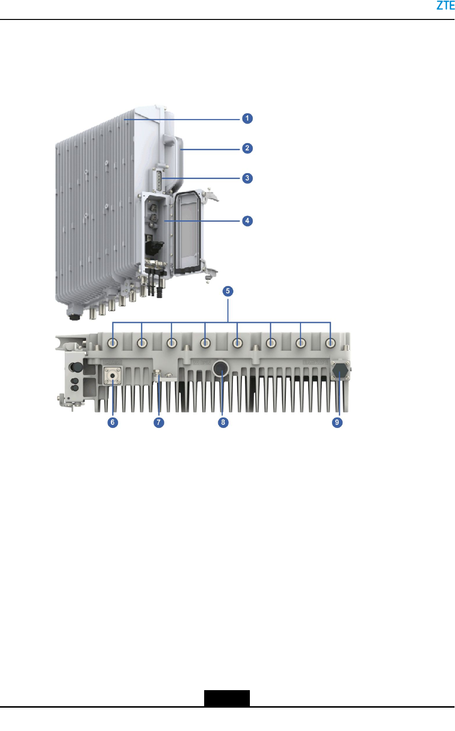
3.2Composition
Figure3-2showsthecompositionoftheZXSDRR8978.
Figure3-2ProductComposition
1.Radiatingpin
2.Handle
3.LEDindicators
4.Operationandmaintenance
cavity
5.Antennainterface
6.CAL/AISGinterface
7.Groundingbolt
8.Breathablevalve
9.EAM/RGPSinterface
lTheoperationandmaintenancecavitycontainsoneDCpowerinterface,twooptical
interfaces(OPT1andOPT2),oneRRULMT/testinterface(LAM/TST).
lTheequipmenthassixLEDindicators.
lAhandleisinstalledontheuppershelltofacilitateinstallationandtransportation.
lAtthebottomoftheequipment,thereareeightantennainterfaces(ANT1–ANT8),one
hermeticseal(breathablevalve),oneantennacalibrationinterface(CAL/AISG),and
onedrycontractuserdeviceinterface(EAM/RGPS).
3-2
SJ-20141113151137-001|2016-08-17(R1.2)ZTEProprietaryandCondential
Chapter3ProductComposition
Note:
TheLMT/TSTinterfaceisusedforZTEmaintenancepersonneltoperformcommissioning
andmaintenance.
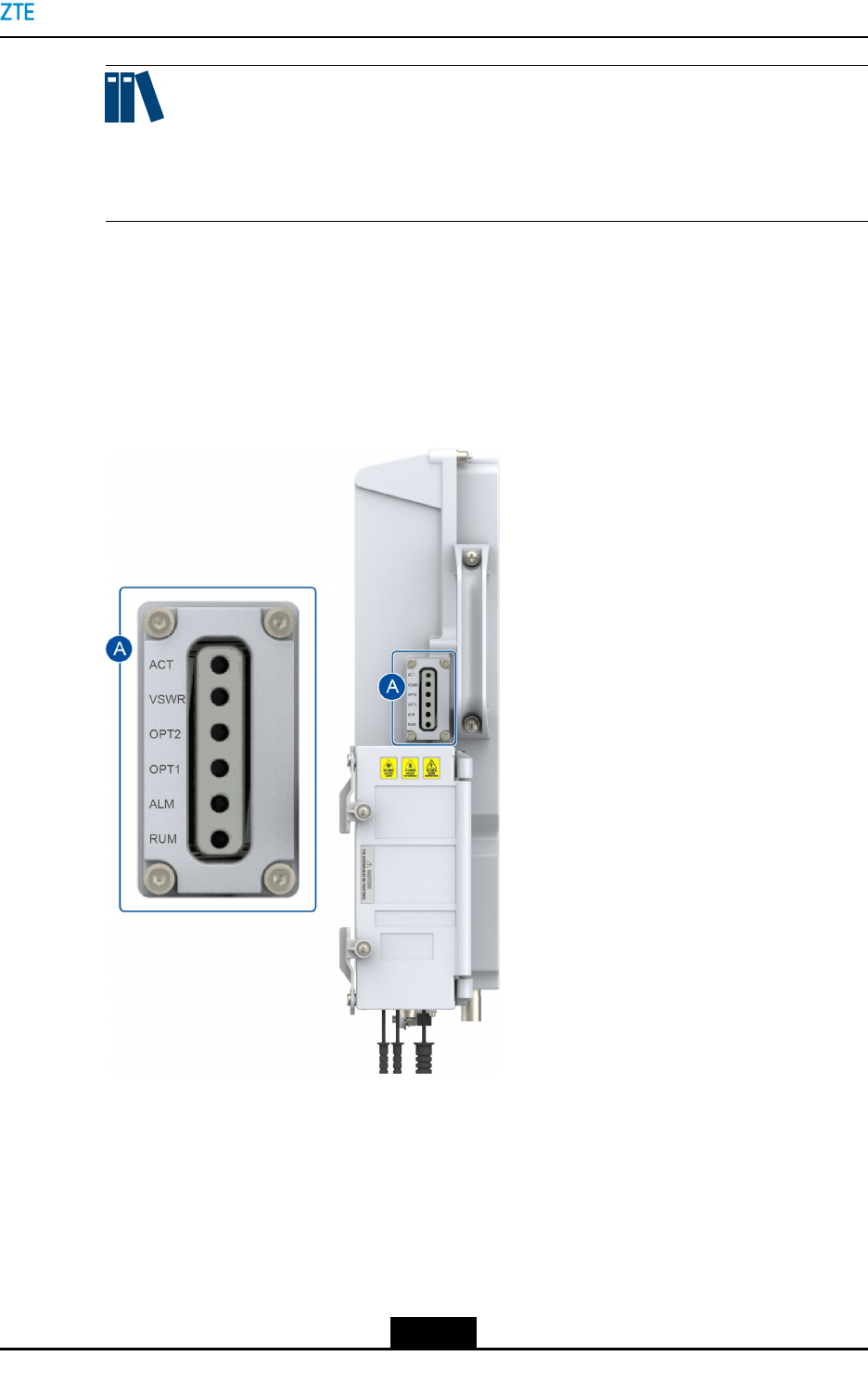
3.3LEDIndicators
Anindicatorindicatestheoperatingstatusofadevice.Figure3-3showsthepositionsof
theindicators.
Figure3-3LEDIndicators
Table3-2describestheLEDindicators.
3-3
SJ-20141113151137-001|2016-08-17(R1.2)ZTEProprietaryandCondential
ZXSDRR8978UserManual
Table3-2IndicatorDescriptions
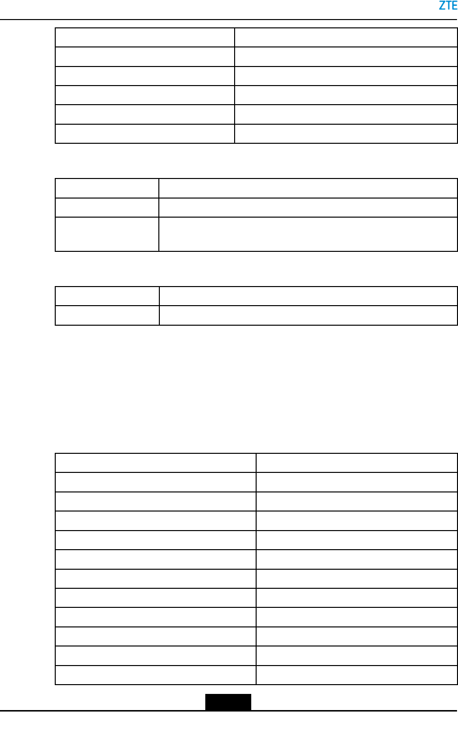
NameIndicationColorDescription
OFF:Thesystemisnotpowered.
ON:Thesystemispowered.Thesoftwaresystemisnot
running.
Flashingslowly(ONfor1sandOFFfor1s):Thesystemis
powered.Thesoftwaresystemisbeingstarted.
Flashingnormally(ONfor0.3sandOFFfor0.3s):The
systemispowered.Thesoftwaresystemhasbeenstarted.
ThecommunicationbetweentheRRUandBBUisnormal.
RUNOperation
indicator
Green
Flashingfast(ONfor70msandOFFfor70ms):Thesystem
ispowered.Thesoftwaresystemhasbeenstarted.Thelink
betweentheZXSDRR8978andBBUisnotestablished.
OFF:Thereisnoalarm. ALMAlarmindicatorRed
ON:Thereisanalarm.
OFF:Theopticalinterfacedoesnotreceiveopticalsignals.
ON:Theopticalinterfacehasreceivedopticalsignalsand
thelinkisnotsynchronized.
OPT1Indicatorof
opticalinterface
1
Green
Flashing(ONfor0.3sandOFFfor0.3s):Theopticalinterface
hasreceivedopticalsignalsandthelinkissynchronized.
OFF:Theopticalinterfacedoesnotreceiveopticalsignals.
ON:Theopticalinterfacehasreceivedopticalsignalsand
thelinkisnotsynchronized.
OPT2Indicatorof
opticalinterface
2
Green
Flashing(ONfor0.3sandOFFfor0.3s):Theopticalinterface
hasreceivedopticalsignalsandthelinkissynchronized.
OFF:VSWRsatallantennainterfacesofthetransmitting
linksarenormal.
VSWRIndicatorof
theVSWRat
theantenna
interface
Red
ON:ThereisaVSWRalarmattheantennainterfaceofthe
transmittinglink.
SolidON:Indicatesthattheradiolinksaresuccessfully
established,andcellsareestablished.
ACTRadiolink
statusindicator
Green
OFF:Indicatesthatnoradiolinksareestablishedor
establishmentfailed,andnocellexists.
•TheALMindicatordoesnotindicatealarmsoftheopticalinterfaces(OPT1andOPT2)andVSWR
alarmsattheantennainterfaces.
3-4
SJ-20141113151137-001|2016-08-17(R1.2)ZTEProprietaryandCondential
Chapter3ProductComposition
3.4PhysicalInterfacesandCables
3.4.1ProtectiveGroundingCable
Function
Theprotectivegroundingpointislocatedatthebottomofthehandle.
Theprotectivegroundingcableprovidesprotectivegroundforthesystem.Thereareatotal
oftwoboltsthatprovideagroundingconnectiontotheZXSDRR8978.Thegroundingbolt
canbeconnectedwithadualholeOTterminalthatcomplieswiththeGR1089specication.
TheOTterminalcanbeconnectedtothe16mm2multi-coresyellow-greencopperwire.
ExternalView
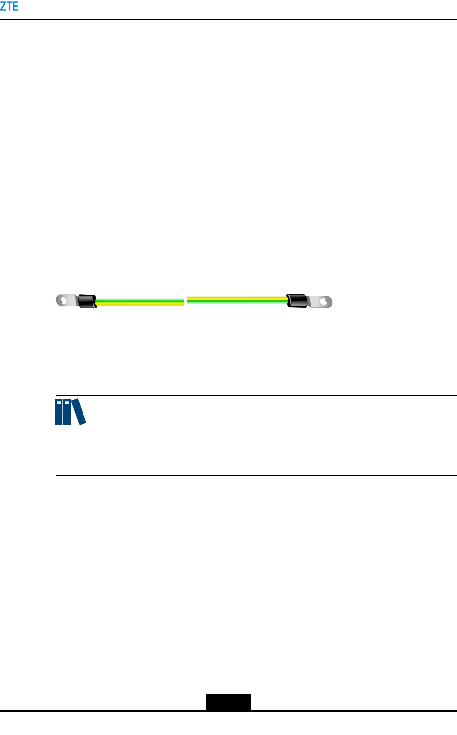
Theprotectivegroundingcableisa16mm2yellow/greencable.Figure3-4showsthe
externalview.
Figure3-4ProtectiveGroundingCable
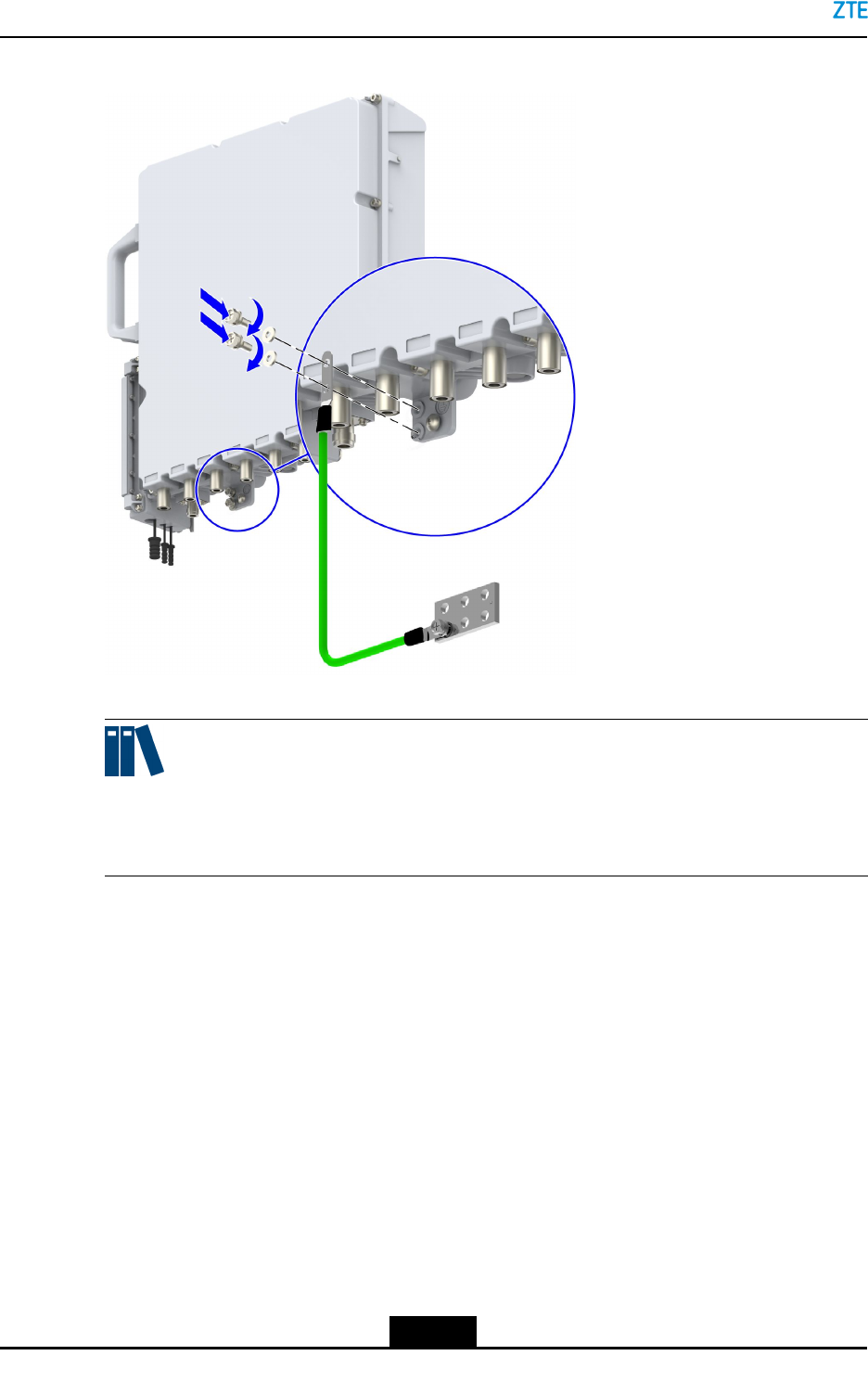
Connection
EndAisconnectedtothegroundinginterfaceoftheZXSDRR8978.EndBisconnected
totheexternalgroundingbar.
Note:
TheconnectionareaofthegroundingboltandOTterminalshallnotbelessthanthearea
oftheOTterminal,andtheconnectionresistancemustbelessthan50mΩ.
Figure3-5illustratesthecableconnection.
3-5
SJ-20141113151137-001|2016-08-17(R1.2)ZTEProprietaryandCondential
ZXSDRR8978UserManual
Figure3-5ConnectionoftheProtectiveGroundingCable
Note:
Thetwoboltsontheleftareusedforinstallingtheprotectivegroundingcable.Thebolton
therightisonlyusedforxinganddoesnotconnecttoanycable.
3.4.2DCPowerInputCable
Function
TheDCpowerinputinterfaceislocatedintheoperationandmaintenancecavityofthe
ZXSDRR8978.
TheDCpowerinputcableleadstheexternalDCpowerintotheoperationandmaintenance
cavityoftheZXSDRR8978.ItconnectstotheDCpowerthroughadual-coreDCbracket
andadual-coreDCconnector,toprovide-48VDCpowerinputfortheRRU.
3-6
SJ-20141113151137-001|2016-08-17(R1.2)ZTEProprietaryandCondential
Chapter3ProductComposition
Caution!
The10mm2DCpowercablecannotbedirectlyconnectedtotheZXSDRR8978,and
needstobeconvertedtoa4mm2DCpowercablethroughajunctionboxbeforeconnecting
totheZXSDRR8978.
TheZXSDRR8978doesnothaveanACpowerinterface.TheACpowershouldbe
convertedintoDCpowerthroughtheoutdoorACpowerlighteningprotectionboxand
thenconnectedtotheZXSDRR8978.
ExternalView
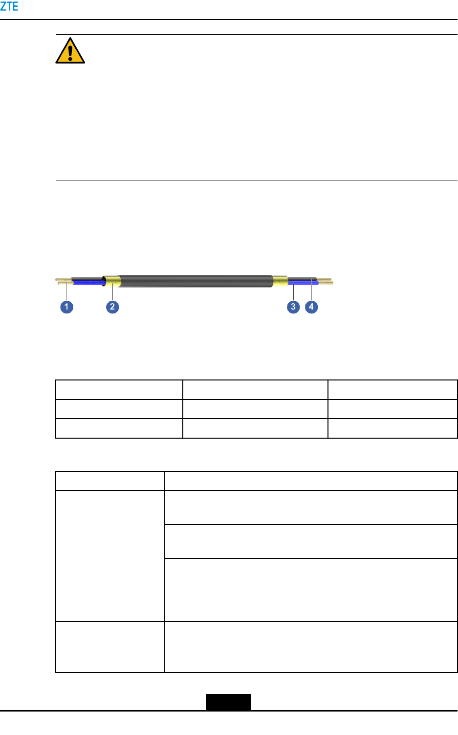
TheDCpowercableisablue-blackcable.Figure3-6showstheexternalview.
Figure3-6DCPowerInputCable
1.Copperwire
2.Shieldinglayer
3.-48Vcore
4.-48VGNDcore
SignalDescription
SignalNameSignalMeaningWireColor
-48V-48VpowerBlue
-48VGND-48VgroundBlack
Connection
If...Then...
Thejunctionboxisnotrequirediftheindoorpowerlighteningprotection
boxisneartotheZXSDRR8978andvoltagedropcanbeignored.
TheindoorDCpowerdistributionunit(withapowerswitch)connectsto
thelightingprotectionboxoftheindoorDCpowersupply.
UsetheDCpowersupply
withoutajunctionbox
ConnecttheZXSDRR8978totheindoorDCpowerlightingprotection
box(thereareatotalofthreeoutputsintheindoorDCpowerlighting
protectionbox,eachofwhichhasanairswitchandcanbeconnected
toanRRU).
IfvoltagedropoccursduetothedistancebetweentheZXSDRR8978
andtheindoorDCpowerlightingprotectionbox,apowercablewitha
largerdiametersizeisneededtoreducethevoltagedropcausedbylong
UsetheDCpowersupply
withajunctionbox
3-7
SJ-20141113151137-001|2016-08-17(R1.2)ZTEProprietaryandCondential
ZXSDRR8978UserManual
If...Then...
distancetransmission.Ajunctionboxisneededtoconvertthecablesto
adifferentsize.
TheindoorDCpowerdistributionunit(withapowerswitch)connectsto
thelightingprotectionboxoftheindoorDCpowersupply.
ConnectthejunctionboxtotheindoorDCpowerlightingprotection
box(thereareatotalofthreeoutputsintheindoorDCpowerlighting
protectionbox,eachofwhichhasanairswitchandcanbeconnected
toanRRU).
AftertheDCpowercableisconvertedbythejunctionbox,itcanbe
connectedtotheZXSDRR8978.
ThejunctionboxisnotrequiredbecausetheACpowersupplyislowwith
alargevoltageandvoltagedropcanbeignored.
ConnecttheindoorACpowerdistributioncabinettotheoutdoorAC
powerlighteningprotectionbox(thereareatotalofthreeoutputsinthe
indoorACpowerdistributioncabinet,eachofwhichhasapowerswitch
andcanbeconnectedtoanRRU).
UsetheACpowersupply
withoutajunctionbox
ConnecttheoutdoorACpowerlighteningprotectionboxtotheZXSDR
R8978.
Figure3-7illustratesthecableconnection.
Figure3-7ConnectionofDCPowerInputCable
3-8
SJ-20141113151137-001|2016-08-17(R1.2)ZTEProprietaryandCondential
Chapter3ProductComposition
Note:
lThetwocoresoftheDCpowercableEndAshouldbewrappedwithatubeterminal.
AfterthetubeterminaliscrimpedandinsertedtothedualcoreDCconnector,theDC
powercablecanbeinsertedtothedualcoreDCsocketthroughtheDCconnector.
lTheEndBoftheDCpowercableisbareandconnectstotheexternalpowersupply.
lThetwoendsofthepowercablemustbemadeatthesite.
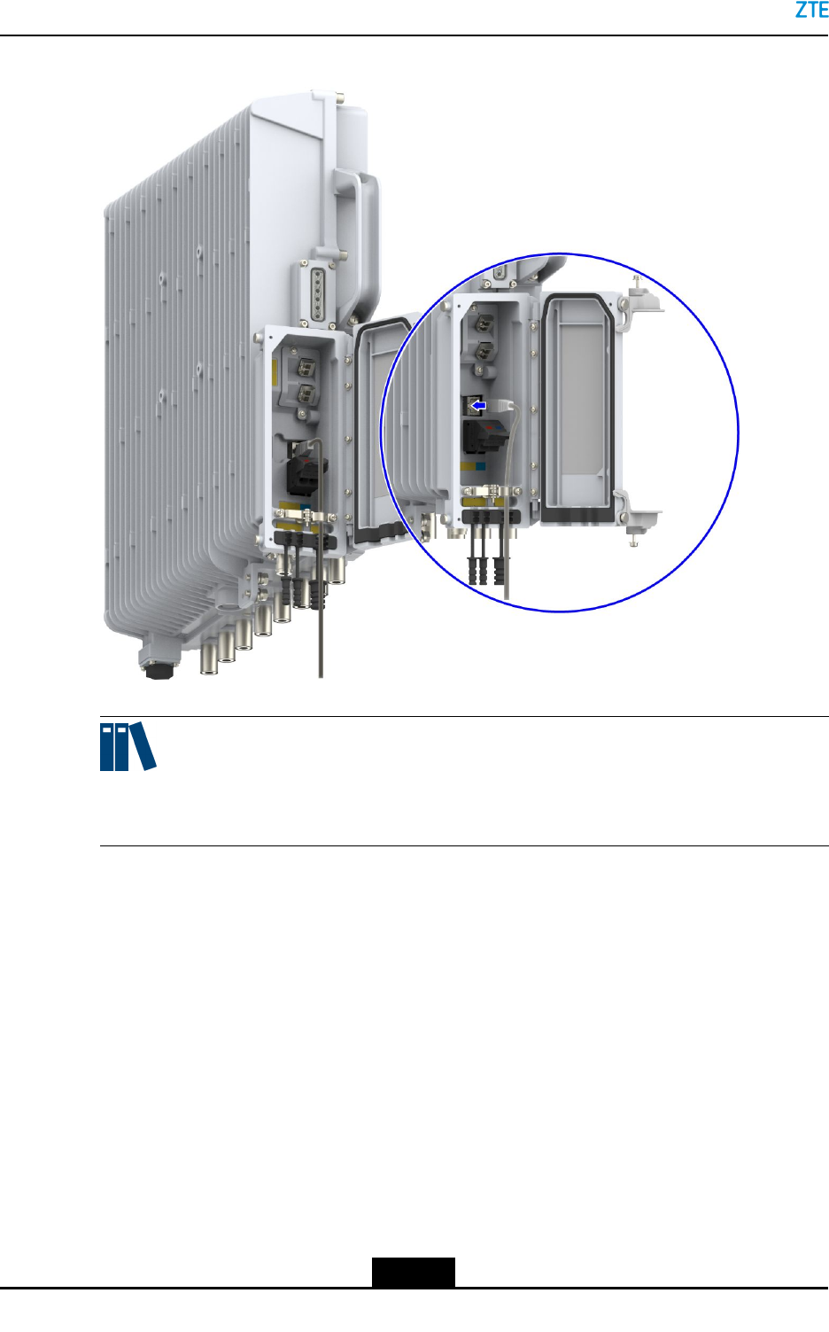
3.4.3LMT/TSTInterfaceCable
Function
TheLMT/TSTinterfaceislocatedintheoperationandmaintenancecavity.ItusesanRJ45
socket.
TheLMTinterfaceisusedfortheinteractionbetweentheLMTandZXSDRR8978through
anEthernetportusingTCP/IP.TELNETcommandlinesaresupported.
Connection
EndAisconnectedtotheLMTinterfaceintheoperationandmaintenancecavity.EndB
isconnectedtotheLMTorPC.
Figure3-8illustratesthecableconnection.
3-9
SJ-20141113151137-001|2016-08-17(R1.2)ZTEProprietaryandCondential
ZXSDRR8978UserManual
Figure3-8ConnectionoftheLMT/TSTInterfaceCable
Note:
TheLMT/TSTinterfaceisusedforZTEmaintenancepersonneltoperformcommissioning
andmaintenance.
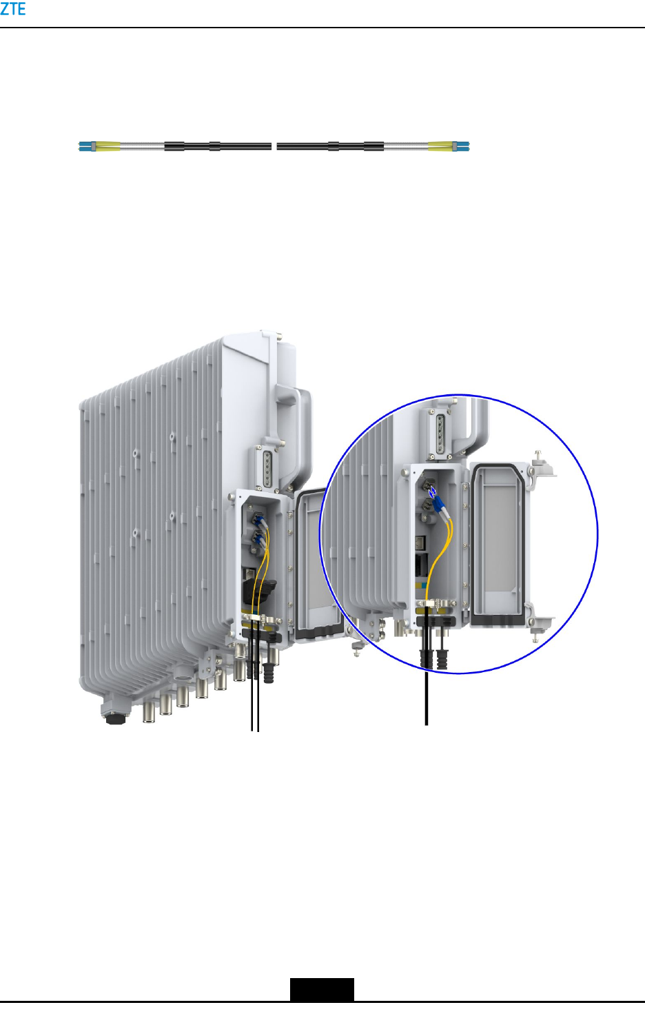
3.4.4OpticalFiber
Function
TheZXSDRR8978hastwoopticalinterfaces,OPT1andOPT2.Theyarelocatedinthe
operationandmaintenancecavity.LC-typeopticalberconnectorsaresupported.
IntheZXSDRR8978system,theopticalinterfaceshavethefollowingfunctions:
lOPT1andOPT2canconnecttheRRUtoanupstreamBBU,tocarrytheIQdataand
communicationsignalingbetweentheRRUandBBU.
lIftheRRUservesastheupstreamRRU.oneopticalinterfacecanbeusedtocascade
adownstreamRRU.
lIftheRRUservesasthedownstreamRRU,oneopticalinterfacecanbeusedto
cascadeanupstreamRRU.
3-10
SJ-20141113151137-001|2016-08-17(R1.2)ZTEProprietaryandCondential
Chapter3ProductComposition
ExternalView
TheopticalberusesLC-typeconnectors.Figure3-9showstheexternalview.
Figure3-9OpticalFiber
Connection
EndAisconnectedtotheopticalports(OPT1andOPT2)oftheZXSDRR8978.EndBis
connectedtotheBBU/dowstreamRRU/upstreamRRU.
Figure3-10illustratesthecableconnection.
Figure3-10ConnectionoftheOpticalFiber
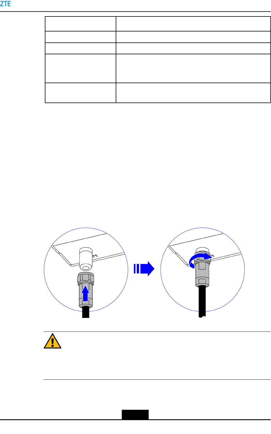
3.4.5AntennaFeederInterfaceCable
Function
Theantennafeederinterfaceislocatedontheexternallterattheequipmentbottom.It
usesN-typefemaleconnectors.
TheantennafeederinterfacecableconnectstheantennainterfaceoftheZXSDRR8978
totheantenna.Itisusedforthesignalreceivingandtransmissionattheantenna.
3-11
SJ-20141113151137-001|2016-08-17(R1.2)ZTEProprietaryandCondential
ZXSDRR8978UserManual
ExternalView
Theantennafeederinterfacecableisa50Ωcablewithadiameterof1/2in(1in=25.4
mm).BothendsareN-typemaleconnectors.Figure3-11showstheexternalview.
Figure3-11AntennaFeederInterfaceCable
Connection
EndAisconnectedtotheANTinterfaceoftheZXSDRR8978.EndBisconnectedtothe
correspondinginterfaceofthemainantennafeeder.
Theantennafeederinterfacecableisa1/2inchjumper.Figure3-12illustratesthecable
connection.
Figure3-12ConnectionoftheAntennaFeederInterfaceCable
3-12
SJ-20141113151137-001|2016-08-17(R1.2)ZTEProprietaryandCondential
Chapter3ProductComposition
3.4.6CAL/AISGInterfaceCable
Function
TheCALinterfaceislocatedattheexternallteratthebottomoftheZXSDRR8978.It
usesatype-Nfemaleconnector.
TheCALinterfacecableusedbytheZXSDRR8978usesajumperwithadiameterof1/2
inch.BothendsareN-typemaleconnectors.TheCALinterfacesupportsantennachannel
calibrationandAISGforRETantennas.
TheCALinterfaceintegratesAISGandantennacalibration.IfanRETantennaisused,the
CALinterfaceoftheZXSDRR8978isconnectedtotheintegratedinterfaceoftheantenna.
ExternalView
TheCALinterfacecableisanRFcablewithadiameterof1/2in(1in=25.4mm).Both
endsareN-typemaleconnectors.Figure3-13showstheexternalview.
Figure3-13CALInterfaceCable
Connection
EndAisconnectedtotheCALinterfaceoftheZXSDRR8978.EndBisconnectedtothe
CALinterfaceoftheantenna.
Figure3-14illustratesthecableconnection.
3-13
SJ-20141113151137-001|2016-08-17(R1.2)ZTEProprietaryandCondential

ZXSDRR8978UserManual
Figure3-14ConnectionoftheCALInterfaceCable
3.4.7EAM/RGPSInterfaceCable
Function
Thedrycontact(EAM)interfaceislocatedattheexternallteratthebottomoftheZXSDR
R8978.Itusesaneight-coreroundconnector.ItsupportstheRGPSfunctionsandone
drycontractinputtotransparentlytransmittheexternaldevicestatus.
TheRGPSreceiverislocatedattheGPSreceivingantenna.Installedneartheantenna,
thesatellitecardtransmitstheoutputdigitalsignaltotheclockmaincontrolcardthrough
adifferentialline.BecausedigitalsignaltransmissionisnotaffectedbyRFsignal
attenuation,theremotedistanceislongandgoodreliabilityandmaintainabilityisensured.
Connection
EndAisconnectedtotheEAMinterfaceoftheZXSDRR8978.EndBisconnectedtothe
drycontactoutput/RGPSinterfaceoftheexternaldevice.
3.5ExternalCableConnection
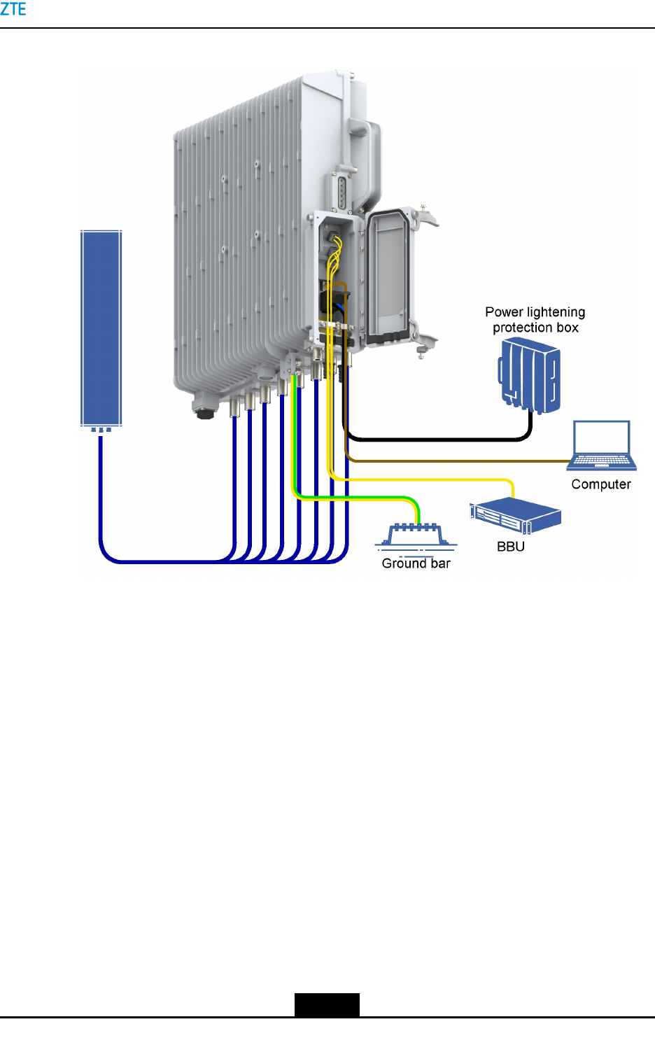
Figure3-15illustratestheexternalcableconnection.
3-14
SJ-20141113151137-001|2016-08-17(R1.2)ZTEProprietaryandCondential
Chapter3ProductComposition
Figure3-15ExternalCableConnection
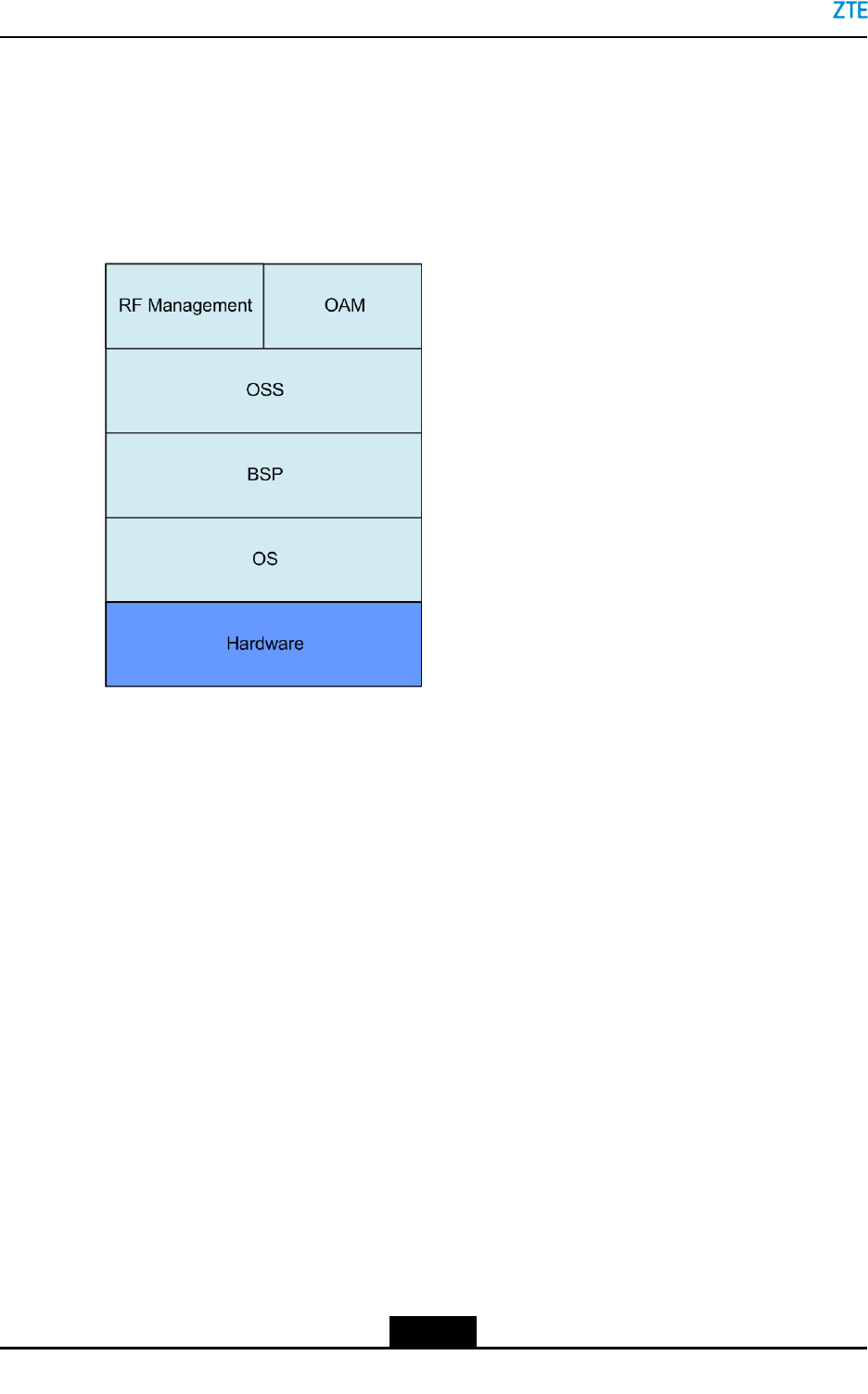
3.6SoftwareComposition
TheZXSDRR8978softwaresystemiscomposedof:
lRFmanagement
IncludesRFmaincontrolandRFchannelmanagement.
lOAMadaptationsoftware
Providesanadaptationinterfaceforentireoperationandmaintenance.
ProvidesthefollowingOAMfunctions:congurationmanagement,version
management,performancestatistics,testmanagement,securitymanagement,
diagnostictest,systemcontrol,andcommunicationprocessing.
lOSS
UsesanSDRplatformarchitecture.
Providesthefunctionssuchasschedulingmanagement,memorymanagement,and
timermanagement.
lBSP
3-15
SJ-20141113151137-001|2016-08-17(R1.2)ZTEProprietaryandCondential

Chapter4
OperationandMaintenance
TableofContents
TechnicalSupport.......................................................................................................4-1
FaultLocation.............................................................................................................4-2
EquipmentMaintenance.............................................................................................4-3
PowerOn...................................................................................................................4-4
PowerOff...................................................................................................................4-5
PartsReplacement.....................................................................................................4-6
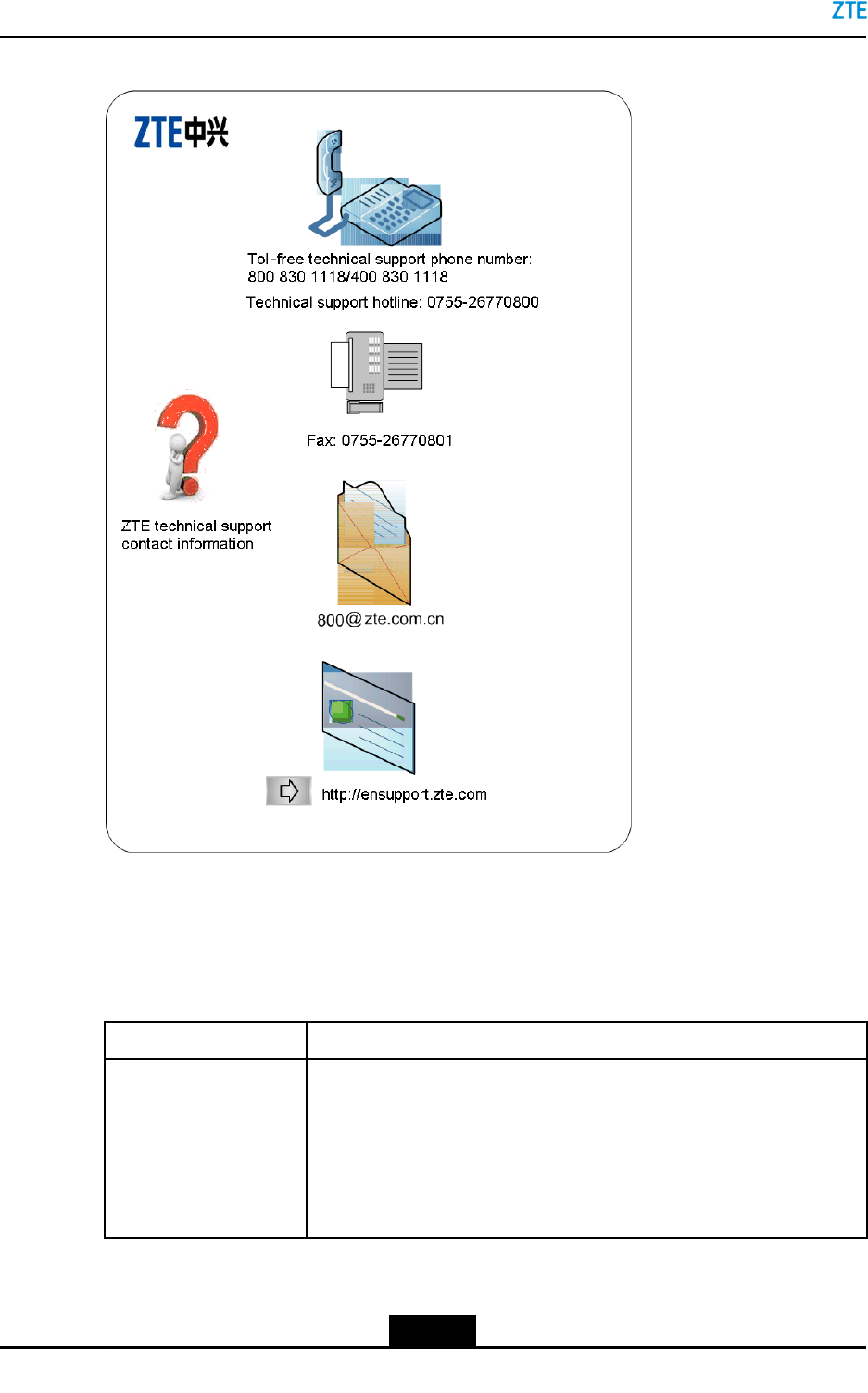
4.1TechnicalSupport
ZTEtechnicalsupportcontractinformationispastedinaconspicuouspositioninthe
equipmentroom,seeFigure4-1.
4-1
SJ-20141113151137-001|2016-08-17(R1.2)ZTEProprietaryandCondential
ZXSDRR8978UserManual
Figure4-1ZTETechnicalSupportContactInformation
4.2FaultLocation
Forthefaultlocationmethodsinroutinemaintenance,refertoT able4-1.
Table4-1FaultLocationMethods
MaintenanceMethodDescription
CheckingAlarmsand
OperationLogs
Thisisthemostcommonmethodfortroubleshooting.Bycheckingthe
alarmmanagementtaboftheoperationandmaintenancesystem,you
cancheckthealarmsandoperationlogs.
lCheckandanalysisofthecurrent,historicalalarmsandcommon
noticationsthroughthealarmmanagementtab,tondtheabnormal
status,locatingandhandlingfaults.
4-2
SJ-20141113151137-001|2016-08-17(R1.2)ZTEProprietaryandCondential
Chapter4OperationandMaintenance
MaintenanceMethodDescription
lBycheckingtheoperationlogsinusermanagement,youcan
tracesystemparametermodication,locaterelevantterminalsand
operators,anddiscoverthefaultscausedbymanualoperations.
PerformanceAnalysisBycheckingtheperformancemanagementtab,youcancreatedifferent
performancetesttasks,generatetherelevantperformancereportsto
determinethesystemperformanceindexes.Byanalyzingthisinformation,
youcanndtheloaddistributioninthenetworkandadjusttherelevant
networkparameters,toimprovetheintegratednetworkperformancein
time.
InstrumentandMeter
Analysis
Auxiliaryinstruments,suchastestUE,signalinganalyzers,andbit
erroranalyzers,canbeusedforfaultanalysis,faultlocationand
troubleshooting.
ReplacementYoucanreplaceafaultypartwithasparepartorapeerpartthatoperates
properlyinthesystemtolocateafault.Forfaultlocationbyusing
thereplacementmethod,youneedtoperformrelevantoperationsin
accordancewiththereplacementproceduresdescribedinthismanual.
Self-testThesystemperformsaself-testwhenitispoweredonagain.Duringthe
self-test,theindicatorsashinaccordancewithrelevantrules.Youcan
locatefaultsbycheckingtheindicators.
IntegratedMethodInactualoperation,allthemethodscanbeusedfortroubleshooting.You
canhandledifferentfaultsbasedonthefaultlocationmethodsandpast
experience.
4.3EquipmentMaintenance
ForadescriptionoftheZXSDRR8978equipmentmaintenance,refertoTable4-2.
Table4-2EquipmentMaintenance
ItemDescriptionFre-
quency
CheckequipmentsurfaceCheckwhethertheequipmentisdamagedorcrackedQuarterly
Checktheequipment
cleancondition
Checkwhetherthereisdepositeddustontheequipment
surface.Ifyes,youneedtocleanthedust.
Quarterly
ChecklabelsCheckwhethertheequipmentandcablelabelsareclean
andclear.
Quarterly
CheckindicatorsInaccordancewiththedescriptionfortheindicators,check
theindicatorstatus.Ifanyfaultoccurs,handleitassoon
aspossible.
Monthly
4-3
SJ-20141113151137-001|2016-08-17(R1.2)ZTEProprietaryandCondential
ZXSDRR8978UserManual
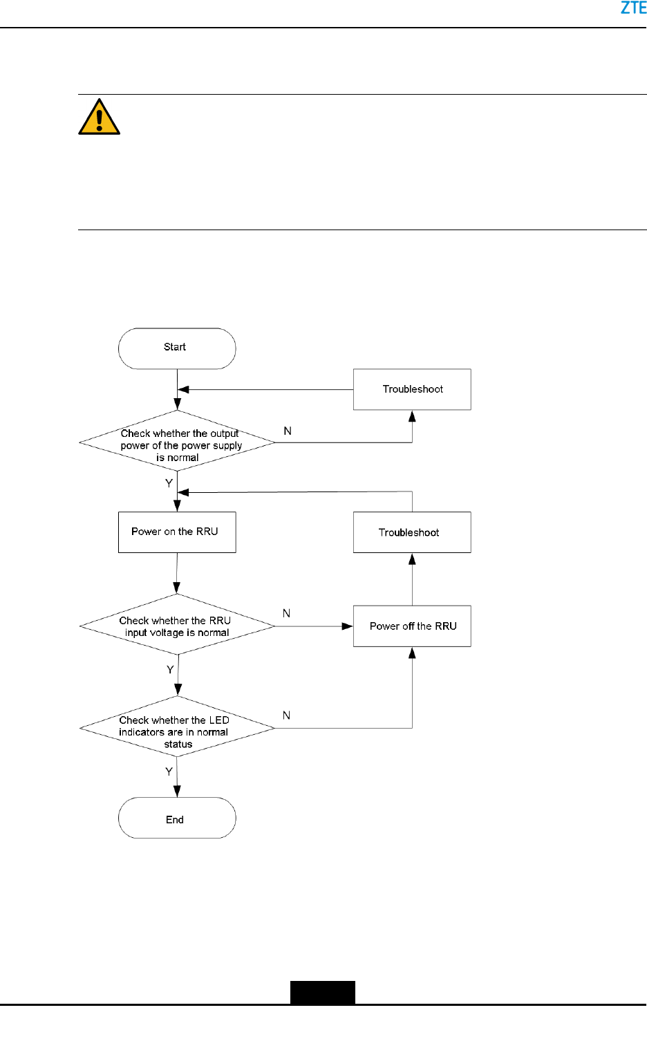
4.4PowerOn
Caution!
Beforepoweron,youneedtochecktheequipmentandcableinstallationindetail,
toensurethatalltheinstallationresultscomplywiththeengineeringinstallation
specications.
Figure4-2showsthepower-onow.
Figure4-2Power-onFlow
ForadescriptionoftheZXSDRR8978power-onow,refertoT able4-3.
4-4
SJ-20141113151137-001|2016-08-17(R1.2)ZTEProprietaryandCondential
Chapter4OperationandMaintenance
Table4-3Power-onSteps
ItemPower-onSteps
DCpower
supply
1.Turnontheswitchofthepowerdistributionunit,andcheckwhethertheequipment
outputvoltageisinthenormalrange.
2.TurnontheswitchoftheindoorDCpowerlightingprotectionboxoftheZXSDR
R8978.PowertheZXSDRR8978on,andtestwhethertheRRUinputvoltage
isinthenormalrange.
3.CheckwhethertheBBUindicatorortheRRUindicatorisnormal.
ACpower
supply
1.TurnontheswitchoftheACpowerdistributionunitoftheZXSDRR8978,and
checkwhethertheequipmentoutputvoltageisinthenormalrange.
2.CheckwhethertheBBUindicatorortheRRUindicatorisnormal.
Note:
Toavoidcurrentsurge,youneedtopowerontheRRUsinthecellsequenceevery30
s.Atthesametime,youcancheckwhetherthecablesofacellareconnectedproperly
throughtheBBUindicator.
4.5PowerOff
Power-offoftheZXSDRR8978includes:
lEmergencypower-off:occurswhentheequipmentroomisonre,oodingorinsmog.
lCommonpower-off:occursinsomeapplicationscenarios,forexample,equipment
moveorexpectedlocalpoweroutage.
ForadescriptionoftheZXSDRR8978power-offow,refertoTable4-4.
Table4-4Power-offSteps
ItemEmergencyPower-offCommonPower-off
DCpowersupplyTurnofftheairswitch
oftheindoorDCpower
distributionunit.
1.TurnofftheairswitchoftheDCpower
lightingprotectionboxoftheZXSDR
R8978.
2.TurnofftheairswitchoftheindoorDC
powerdistributionunit.
ACpowersupplyTurnofftheairswitchoftheindoorACpowerdistributionunit.
4-5
SJ-20141113151137-001|2016-08-17(R1.2)ZTEProprietaryandCondential
ZXSDRR8978UserManual
4.6PartsReplacement
4.6.1ReplacingtheZXSDRR8978
LocatetheZXSDRR8978faultsthroughobservationandanalysis,anddeterminewhether
toreplacetheZXSDRR8978.ReplacingtheZXSDRR8978willinterruptalltheservices
carriedbytheZXSDRR8978.
Prerequisite
lVerifythehardwaretypeofthefaultyZXSDRR8978.PrepareaproperZXSDR
R8978.ThespecicationsoftheproperZXSDRR8978mustbeconsistentwiththe
faultyone.
lPreparethefollowingtools.
ToolFunction
WrenchInstallsoruninstallstheRFcables
M5crossscrewdriverInstallsoruninstallstheZXSDRR8978maintenancecavity,or
fastensthescrewsandprotectiongroundingcables.
WaterprooftapeProvideswaterproofprotectionfortheRFcableconnectors
StickerMarkstheconnectionofthecablestobereplaced(afterthe
replacement,allthecablesmustbereconnectedtotheplace
wheretheywere)
Moistureproofantistatic
bagandcarton
StoresthefaultyZXSDRR8978
Steps
1.PowerofftheZXSDRR8978.
2.OpenthecoveroftheZXSDRR8978maintenancecavitybyusingtheM5screwdriver.
3.Pastealabelateachendofeveryopticalber.
4.RemovethexscrewsfromthecablecrimperbyusingtheM5screwdriver.
5.PulluptheinsulatingpartofthedualcoreDCconnectoragainstthedirectionofthe
arrowmarkedontheshell.Pullouttheconnectoranduninstallthepowercables.
6.Pressthebluecrimperoftheber,andpulltheberoutoftheconnector.
7.UsetheM5crossscrewdrivertoremovethegroundingboltandremovetheprotective
groundingcable.
8.Removeallthewaterprooftapesfromthejumpersoftheantennaport.Uninstall
thejumperfromtheZXSDRR8978antennaportbyusingthewrenchwithinsulation
protectivetreatment.
9.UninstalltheAISG/EAMcable.
4-6
SJ-20141113151137-001|2016-08-17(R1.2)ZTEProprietaryandCondential
Chapter4OperationandMaintenance
10.TightenthejackingscrewclockwiseandjacktheZXSDRR8978chassis.Then,loosen
theplate-pressingboltanti-clockwise.
11.PulluptheZXSDRR8978fromthepoleorwall-mountingbracket,andremovethe
ZXSDRR8978.
12.Putthefaultyequipmentintothemoistureproofantistaticbag.Labeltheequipment
model,sectorIDandfaultinformationonthebag.Putthefaultyequipmentintothe
cartonandlabelthesameinformationastheantisaticbag.
13.Reinstallallequipmentpartsandtighteneveryscrew.
14.Connectallcableswithwaterproofandinsulationprotectivetreatment.
15.PowerontheZXSDRR8978.
16.TheZXSDRR8978performtheself-testprocessafteritispoweredon.Duringthe
self-test,youneedtoobservetheindicatorstatusandperformoperationsaccordingly.
If...Then...
Theindicatorisnormal,whichmeans
thatservicesarerestored.
Theself-testandreplacementaresuccessful.
Theindicatorisabnormal,whichmeans
thatservicesarenotrestored.
Troubleshootthefaultandhandletherelevantalarms,or
contactZTEtechnicalsupport.
–EndofSteps–
4.6.2ReplacingtheOpticalModule
Theopticalmoduleprovidestheopticsandelectricalconversion.Replacingtheoptical
modulewillinterruptalltheservicescarriedontheopticalmodule.
Caution!
lTheopticalmodulesupportshotplugging.Beforehotplugging,youmustwearthe
antistaticwriststrap.
lDonotlookdirectlyattheopticalmoduleinsidewhenreplacingtheopticalber,
avoidingdamagetoyoureyes.
Prerequisite
lPrepareaproperopticalmodule.
lTakearecordoftheconnectionpositionatbothendsofthefaultyopticalmodulesand
bers.Markthepositionsbetweentheopticalmoduleandbers.
ToolFunction
AntistaticwriststrapProvidesantistaticprotection
4-7
SJ-20141113151137-001|2016-08-17(R1.2)ZTEProprietaryandCondential

ZXSDRR8978UserManual
ToolFunction
M5crossscrewdriverInstallsoruninstallstheZXSDRR8978maintenancecavity
StickerMarkstheconnectionofthecablestobereplaced(afterthe
replacement,allthecablesmustbereconnectedtotheplace
wheretheywere)
Moisture-proofantistaticbag
andcarton
Storesthefaultyopticalmodule
Steps
1.OpenthecoverofthemaintenancecavitybyusingtheM5screwdriver.
2.Pastealabelateachendofeveryopticalber.
3.Presstheblueclampoftheber,andpulltheberconnectoroutoftheopticalmodule
tobereplaced.
4.Pulltheopticalmoduleoutoftheslot.
5.Installtheproperopticalmoduleintotheslot.
6.Removethedustproofcap,andconnecttheberconnectortothenewopticalmodule.
7.Checkwhethertheopticalmoduleisoperatingproperlyinaccordancewiththe
indicatorstatus.
8.Tightentheberclampandclosethemaintenancecavity.
–EndofSteps–
4.6.3ReplacingtheRFCable
TheRFcabletransmitsorreceivesRFsignals.Locatethefaultsthroughobservationand
analysis,andensurethatwhethertoreplacetheRFcable.ReplacingtheRFcablewill
interruptalltheservicescarriedbytheZXSDRR8978.
Prerequisite
lPrepareaproperRFcabletobereplaced.
EachsitehasasetofRFcablescorrespondingtothesitetype.
àForBTSexpansionormodication,youcanselectasetofRFcables
correspondingtothesitetype.
àForreplacementofasingleRFcable,youcanselectaproperRFcablefromthe
RFcableset.
CheckwhetherthecoreconnectoroftheRFcableisproper.
lPreparethefollowingtools.
4-8
SJ-20141113151137-001|2016-08-17(R1.2)ZTEProprietaryandCondential
Chapter4OperationandMaintenance
ToolFunction
WrenchInstallsoruninstallstheRFcable
WaterprooftapeProvideswaterproofprotectionfortheRFcableconnector
StickerMarkstheconnectionofthecabletobereplaced(afterthe
replacement,thecablemustbereconnectedtotheplacewhere
itwas)
Moisture-proofantistaticbag
andcarton
StoresthefaultyRFcable
Steps
1.PowerofftheZXSDRR8978.
2.RemovethewaterprooftapeoftheRFcable.
3.LoosentheconnectorsoftheRFcablesbyusingthewrench.
4.Putthefaultycableintothemoistureproofantistaticbag.Labelthecablemodel,sector
IDandfaultinformationonthebag.Putthefaultycableintothecartonandlabelthe
sameinformationastheantisaticbag.
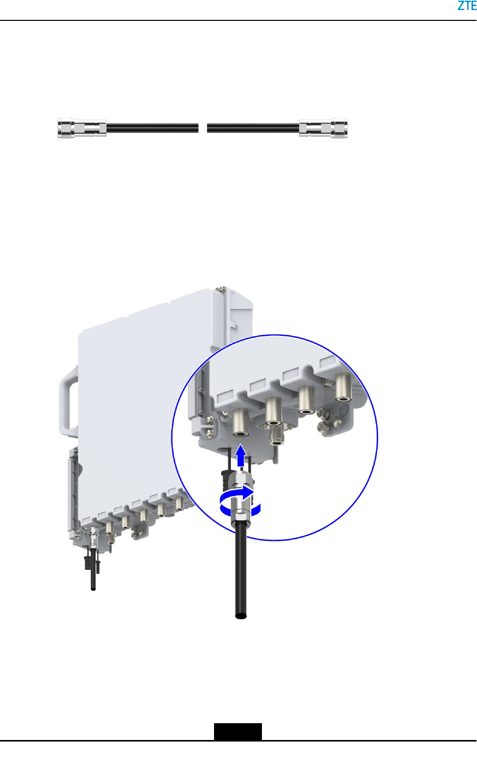
5.ConnecttheproperRFcableinaccordancewiththepreviousconnection,seeFigure
4-3.
Figure4-3ConnectingtheRFcable
Caution!
Duringtheuninstallationprocess,takeofftheconnectorcarefully.Trynottodamage
theconnector.
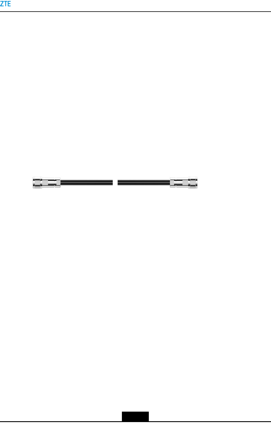
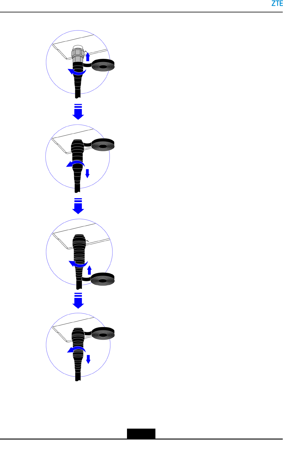
6.WraptheRFcableconnectorswithwaterprooftape,seeFigure4-4.
4-9
SJ-20141113151137-001|2016-08-17(R1.2)ZTEProprietaryandCondential
ZXSDRR8978UserManual
Figure4-4WaterproofTreatment
7.PowerontheZXSDRR8978.
8.TheZXSDRR8978performstheself-testprocessafteritispoweredon.Duringthe
self-test,youneedtoobservetheindicatorstatusandperformoperationsaccordingly.
4-10
SJ-20141113151137-001|2016-08-17(R1.2)ZTEProprietaryandCondential
Chapter4OperationandMaintenance
If...Then...
Theindicatorisnormal,which
meansthatservicesarerestored.
Theself-testandreplacementaresuccessful.
Theindicatorisabnormal,which
meansthatservicesarenot
restored.
Troubleshootthefaultandhandletherelevantalarms,or
contactZTEtechnicalsupport.
–EndofSteps–
4-11
SJ-20141113151137-001|2016-08-17(R1.2)ZTEProprietaryandCondential

ZXSDRR8978UserManual
Thispageintentionallyleftblank.
4-12
SJ-20141113151137-001|2016-08-17(R1.2)ZTEProprietaryandCondential
Chapter5
AccessoryDevices
TableofContents
JunctionBox..............................................................................................................5-1
ACPowerLighteningProtectionBox..........................................................................5-3
ReplacingtheACPowerLightingProtectionBox.......................................................5-6
5.1JunctionBox
Function
WhentheDCpowersupplyisfarfromtheZXSDRR8978,toavoidvoltagedrop,a2×10
mm2DCpowercableneedstobeused.T oconnecttothe2×4mm2DCpowercableused
bytheZXSDRR8978,the2×10mm2DCpowercableshouldbeconvertedthroughthe
junctionbox.
ExternalView
Figure5-1showstheexternalviewofthejunctionbox.
Figure5-1JunctionBox
5-1
SJ-20141113151137-001|2016-08-17(R1.2)ZTEProprietaryandCondential
ZXSDRR8978UserManual
Specications
Table5-1showsthespecicationsofthejunctionbox.
Table5-1JunctionBoxSpecications
NameSpecication
Height×Width×Depth233mm×119mm×55mm(excludingthehandleandwaterproofcap)
InstallationMode
ForsingleRRUpole-mountedinstallationorwall-mountedinstallation,thejunctionboxcan
beinstalledataside(recommended)orthefrontoftheRRUthroughanadaptor.Fortwo
RUUlpole-mountedinstallation,thejunctionboxneedstobeinstalledonthepole.
Figure5-2showshowtoinstallthejunctionboxatasideforexample.
Figure5-2JunctionBoxInstallation
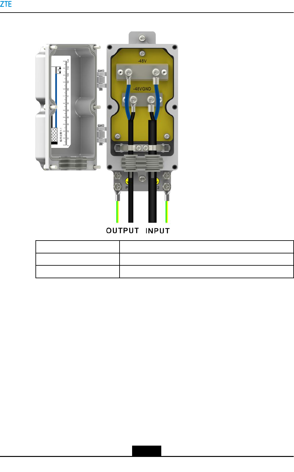
InterfacesandCableConnection
Figure5-3showstheinterfacesandcableconnectionofthejunctionbox.
5-2
SJ-20141113151137-001|2016-08-17(R1.2)ZTEProprietaryandCondential
Chapter5AccessoryDevices
Figure5-3InterfacesandCableConnection
InterfaceNameCableDescription
INPUT2×10mm2DCpowercable
OUTPUT2×4mm2DCpowercable
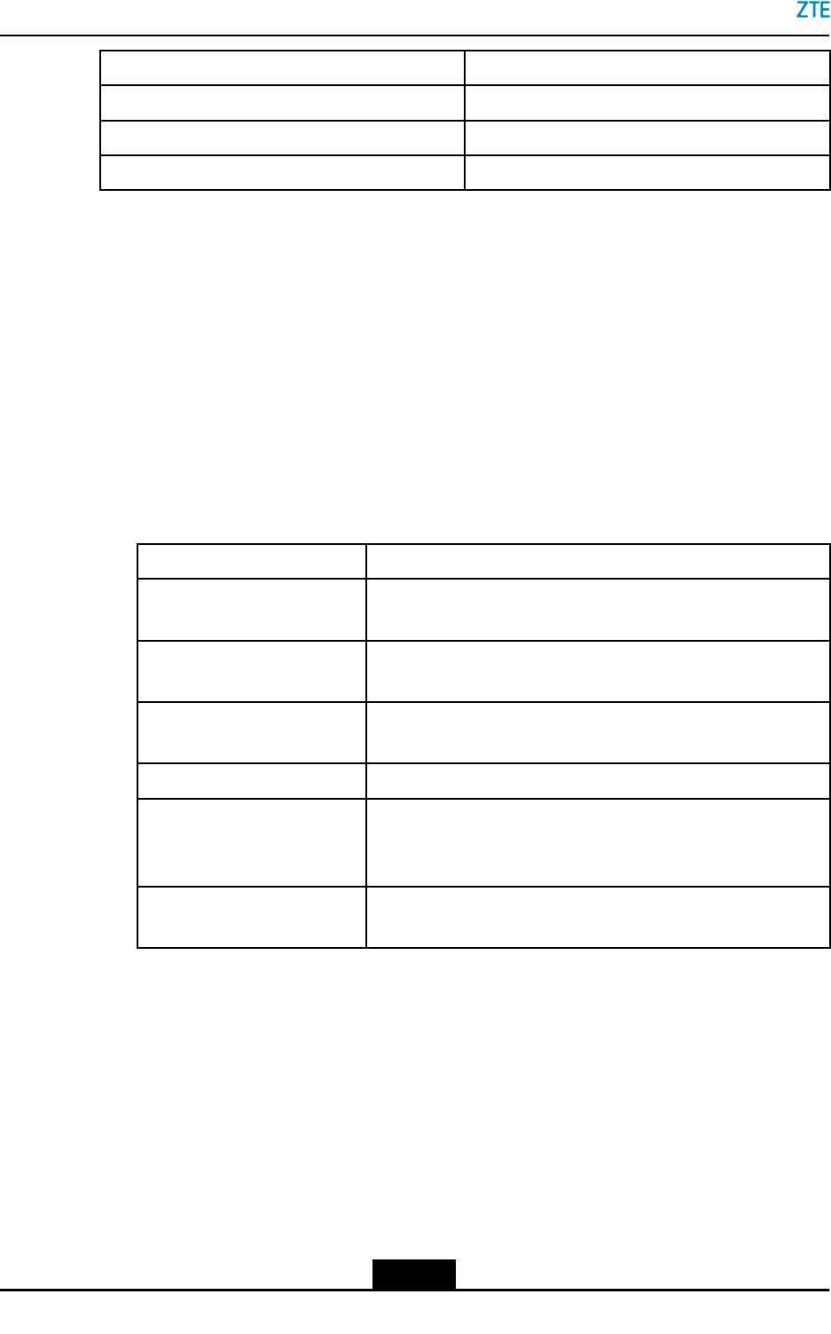
5.2ACPowerLighteningProtectionBox
Function
TheoutdoorACpowerlighteningprotectionboxisPPC33A009.ItprotectstheACcurrent
fromlighteningandcovertsACintotheDCthatisapplicablefortheZXSDRR8978.
ExternalView
Figure5-4showstheexternalviewoftheACpowerlighteningprotectionbox.
5-3
SJ-20141113151137-001|2016-08-17(R1.2)ZTEProprietaryandCondential
ZXSDRR8978UserManual
Figure5-4ExternalView
Specications
Table5-2showsthespecicationsoftheACpowerlighteningprotectionbox.
Table5-2SpecicationsoftheACPowerLighteningProtectionBox
ItemSpecication
Height×Width×Depth300mm×250mm×118mm(excludingthe
handleandwaterproofcap
InstallationmodePole-mountedinstallation,all-mountedinstallation
Lighteningprotectionindex20kA
InstallationModes
TheACpowerlighteningprotectionboxcanbemountedonapoleorwall,seeFigure5-5.
5-4
SJ-20141113151137-001|2016-08-17(R1.2)ZTEProprietaryandCondential
Chapter5AccessoryDevices
Figure5-5InstallationModes
InterfacesandCableConnection
OpentheACpowerlighteningprotectionboxandconnecttheinternalandexternalcables,
seeFigure5-6.
Figure5-6InterfacesandCableConnection
NameDescription
-220AC_L220VACliveline
-220AC_N220VAVneutralline
5-5
SJ-20141113151137-001|2016-08-17(R1.2)ZTEProprietaryandCondential
ZXSDRR8978UserManual
NameDescription
-48VDC-48VDCneutralline
-48VDCRTN-48VDCearthline
PEProtectivegroundingcable
5.3ReplacingtheACPowerLightingProtectionBox
IftheACpowerlightingprotectionboxhasanabnormaloutputbuttheinputisnormal,it
hassomefaultsandshouldbereplacedimmediately.
Prerequisite
lVerifythehardwaretypeofthefaultyACpowerlightingprotectionbox.Preparea
properACpowerlightingprotectionbox.ThespecicationsoftheproperACpower
lightingprotectionboxmustbeconsistentwiththefaultyone.
lPreparethefollowingtools.
ToolFunction
WrenchInstallsoruninstallstheoutdoorACpowerlightingprotection
boxfromapole
M4Inner-hexagonwrenchInstallsoruninstallsthepole-mountedinstallationassemblies,
orfastenstheanti-theftscrews
M6crossscrewdriverInstallsoruninstallsthemountingplateandcablesofthe
outdoorACpowerlightingprotectionbox
WaterprooftapeProvideswaterproofprotectionforthecableconnectors
StickerMarkstheconnectionofthecablestobereplaced(afterthe
replacement,allthecablesmustbereconnectedtotheplace
wheretheywere)
Moistureproofantistaticbag
andcarton
StoresthefaultyACpowerlightingprotectionbox
Steps
1.PowerofftheZXSDRR8978.
2.Removethewaterprooftapefromthecables.UninstallthecablesoftheACpower
lightingprotectionboxbyusingtheM6screwdriver
3.Uninstalltheanti-theftscrewsbyusingtheM4Inner-hexagonwrench,anduninstall
themountingplatebyusingtheM6crossscrewdriver.TaketheACpowerlighting
protectionboxdownfromthepole.
5-6
SJ-20141113151137-001|2016-08-17(R1.2)ZTEProprietaryandCondential

Chapter5AccessoryDevices
4.Putthefaultyequipmentintothemoistureproofantistaticbag.Labeltheequipment
model,sectorIDandfaultinformationonthebag.Putthefaultyequipmentintothe
cartonandlabelwiththesameinformationastheantisaticbag.
5.ReinstalltheproperACpowerlightingprotectionbox,fastentheanti-theftscrews,and
installthemountingplateandcables.Wrapthecableswiththewaterprooftape.
6.PowerontheZXSDRR8978.
–EndofSteps–
5-7
SJ-20141113151137-001|2016-08-17(R1.2)ZTEProprietaryandCondential

ZXSDRR8978UserManual
Thispageintentionallyleftblank.
5-8
SJ-20141113151137-001|2016-08-17(R1.2)ZTEProprietaryandCondential
Chapter6
TechnicalSpecications
TableofContents
PhysicalSpecications...............................................................................................6-1
PerformanceIndexes.................................................................................................6-1
PowerConsumption...................................................................................................6-2
ReliabilityIndexes......................................................................................................6-2
GroundingRequirement.............................................................................................6-3
LighteningandSurgeProtection................................................................................6-3
6.1PhysicalSpecications
Table6-1showsthephysicalspecicationsoftheZXSDRR8978.
Table6-1PhysicalSpecications
ItemSpecication
Dimensions(H×W×D)430mm×400mm×125mm
Weight≤22kg
Volume22L
6.2PerformanceIndexes
Table6-2showstheperformanceindexesoftheZXSDRR8978.
Table6-2PerformanceIndexes
ItemIndex
Dual-polarizedsmartantenna(acommonantennatype)
Eight–antennacirculararraysmartantenna
Supportedantennatypes
RETantenna
ReceiversensitivityTD-LTE:–105dBmperchannel
Frequencydeviation±0.05ppm
InstallationSupportsinstallationintheequipmentroom.
TheZXSDRR8978isgenerallyinstalledoutdoors.For
indoorinstallation,mountitonapoleorwall.
6-1
SJ-20141113151137-001|2016-08-17(R1.2)ZTEProprietaryandCondential
ZXSDRR8978UserManual
ItemIndex
Maximumdistancebetweentheoutdoor
unitandtheantenna
12m
FilterReplaceable
Whethertherateis
downwardcompatible
Yes
Whethertheoptical
modulecanbe
replacedonsite
Yes
Opticalmodule
Rate2×6Gbps/2×10Gbps
OpticalberNumberofcascade
levels/Maximum
distanceofacascade
level
Onecascadelevel/10km
6.3PowerConsumption
Table6-3showsthepowerconsumptionspecicationsoftheZXSDRR8978.
Table6-3PowerConsumptionSpecications
ItemPowerConsumption
DL:UL=2:2400W
DL:UL=3:1580W
6.4ReliabilityIndexes
ForadescriptionofthereliabilityindexesoftheZXSDRR8978,refertoT able6-4.
Table6-4ReliabilityIndexes
ItemIndex
ProtectionlevelIP66
ProtectionmodeCastshell
MTBF>180000h
MTTR<60min
Availability>99.9994%
Serviceinterruptiontime<3min/year
AnnualReturnRate<2%
6-2
SJ-20141113151137-001|2016-08-17(R1.2)ZTEProprietaryandCondential
Chapter6T echnicalSpecications
6.5GroundingRequirement
Inpracticalapplications,thegroundingresistancemustbelessthan10Ω.
6.6LighteningandSurgeProtection
Table6-5showsthelighteningprotectionspecicationoftheZXSDRR8978.
Table6-5LighteningProtectionSpecication
ItemCurrent
Lighteningprotectionspecication20kA
6-3
SJ-20141113151137-001|2016-08-17(R1.2)ZTEProprietaryandCondential

ZXSDRR8978UserManual
Thispageintentionallyleftblank.
6-4
SJ-20141113151137-001|2016-08-17(R1.2)ZTEProprietaryandCondential
Chapter7
EnvironmentRequirements
TableofContents
PowerSupplyRequirements......................................................................................7-1
OperatingEnvironment...............................................................................................7-1
StorageEnvironment..................................................................................................7-2
7.1PowerSupplyRequirements
Table7-1showstherequirementsforthepowersupplyoftheZXSDRR8978.
Table7-1PowerRequirements
ItemRequirement
DCpowersupply-48VDC(uctuationrange:-57VDCto–37VDC)
TheDCpowersupplymustsupporttheanti-reverseconnectionand
over-currentprotectionfunctions.
ACpowersupply100VAC/110VAC/220VAC(uctuationrange:90VACto290VAC)
IftheACpowersupplyisused,theACpowerneedstobeconvertedintoDC
powerthroughtheACpowerlighteningprotectionboxandthenconnected
totheZXSDRR8978.
7.2OperatingEnvironment
TheZXSDRR8978canoperateproperlyinthefollowingconditions:
ClimaticEnvironmentCondition
ItemDescription
Lowedtemperature-40℃
Highesttemperature55℃
Lowestrelativehumidity2%RH
Highestrelativehumidity100%RH
Temperaturechangerate0.5℃/min
Lowestatmosphericpressure70kPa
Highestatmosphericpressure106kPa
7-1
SJ-20141113151137-001|2016-08-17(R1.2)ZTEProprietaryandCondential
ZXSDRR8978UserManual
ItemDescription
Solarradiation1120W/m2
CondensationAllowed
Precipitation(rain,snow,andhail)Allowed
HumidityWetsurfaceisallowed
FreezingandfrostAllowed
BiologicalEnvironmentCondition
ItemDescription
PlantsMoldandfungusareallowed.
AnimalsRodentsandotheranimalsthatdamagetheproductareallowed,except
termites
ChemicalSubstanceEnvironmentCondition
ItemDescription
SaltfogAllowed
7.3StorageEnvironment
Toensurenormaloperationafterinstallation,theZXSDRR8978shouldbestoredina
packageinaplacewithgoodprotection.
ClimaticEnvironmentCondition
ItemDescription
Lowedtemperature-55℃
Highesttemperature70℃
Lowestrelativehumidity10%RH
Highestrelativehumidity100%RH
Temperaturechangerate1℃/min
Lowestatmosphericpressure70kPa
Highestatmosphericpressure106kPa
Solarradiation1120W/m2
CondensationAllowed
Precipitation(rain,snow,andhail)Allowed
HumidityWetsurfaceisallowed
7-2
SJ-20141113151137-001|2016-08-17(R1.2)ZTEProprietaryandCondential
Chapter7EnvironmentRequirements
ItemDescription
FreezingandfrostAllowed
BiologicEnvironmentCondition
ItemDescription
PlantsMoldandfungusareallowed.
AnimalsRodentsandotheranimalsthatdamagetheproductareallowed,excepttermites
ChemicalSubstanceEnvironmentCondition
ItemDescription
SaltfogAllowed
7-3
SJ-20141113151137-001|2016-08-17(R1.2)ZTEProprietaryandCondential

ZXSDRR8978UserManual
Thispageintentionallyleftblank.
7-4
SJ-20141113151137-001|2016-08-17(R1.2)ZTEProprietaryandCondential

Figures
Figure2-1PositionoftheRRUinaNetwork.............................................................2-1
Figure2-2ExternalView...........................................................................................2-3
Figure2-3ExternalInterfaces...................................................................................2-5
Figure2-4ChainNetworking....................................................................................2-6
Figure2-5StarNetworking.......................................................................................2-7
Figure3-1SystemStructure.....................................................................................3-1
Figure3-2ProductComposition................................................................................3-2
Figure3-3LEDIndicators.........................................................................................3-3
Figure3-4ProtectiveGroundingCable.....................................................................3-5
Figure3-5ConnectionoftheProtectiveGroundingCable.........................................3-6
Figure3-6DCPowerInputCable.............................................................................3-7
Figure3-7ConnectionofDCPowerInputCable.......................................................3-8
Figure3-8ConnectionoftheLMT/TSTInterfaceCable..........................................3-10
Figure3-9OpticalFiber..........................................................................................3-11
Figure3-10ConnectionoftheOpticalFiber............................................................3-11
Figure3-11AntennaFeederInterfaceCable...........................................................3-12
Figure3-12ConnectionoftheAntennaFeederInterfaceCable..............................3-12
Figure3-13CALInterfaceCable.............................................................................3-13
Figure3-14ConnectionoftheCALInterfaceCable................................................3-14
Figure3-15ExternalCableConnection..................................................................3-15
Figure3-16SoftwareComposition..........................................................................3-16
Figure4-1ZTET echnicalSupportContactInformation.............................................4-2
Figure4-2Power-onFlow.........................................................................................4-4
Figure4-3ConnectingtheRFcable..........................................................................4-9
Figure4-4WaterproofTreatment............................................................................4-10
Figure5-1JunctionBox............................................................................................5-1
Figure5-2JunctionBoxInstallation..........................................................................5-2
Figure5-3InterfacesandCableConnection.............................................................5-3
Figure5-4ExternalView...........................................................................................5-4
Figure5-5InstallationModes....................................................................................5-5
Figure5-6InterfacesandCableConnection.............................................................5-5
I
SJ-20141113151137-001|2016-08-17(R1.2)ZTEProprietaryandCondential

Figures
Thispageintentionallyleftblank.
II
SJ-20141113151137-001|2016-08-17(R1.2)ZTEProprietaryandCondential

Tables
Table2-1KeyFeaturesoftheZXSDRR8978S2300................................................2-3
Table2-2KeyFeaturesoftheZXSDRR8978S2600M.............................................2-4
Table2-3KeyFeaturesoftheZXSDRR8978S2600L..............................................2-4
Table2-4ExternalInterfaceDescription....................................................................2-5
Table3-1SubsystemDescription..............................................................................3-1
Table3-2IndicatorDescriptions................................................................................3-4
Table4-1FaultLocationMethods.............................................................................4-2
Table4-2EquipmentMaintenance............................................................................4-3
Table4-3Power-onSteps.........................................................................................4-5
Table4-4Power-offSteps.........................................................................................4-5
Table5-1JunctionBoxSpecications.......................................................................5-2
Table5-2SpecicationsoftheACPowerLighteningProtectionBox.........................5-4
Table6-1PhysicalSpecications..............................................................................6-1
Table6-2PerformanceIndexes................................................................................6-1
Table6-3PowerConsumptionSpecications............................................................6-2
Table6-4ReliabilityIndexes.....................................................................................6-2
Table6-5LighteningProtectionSpecication............................................................6-3
Table7-1PowerRequirements.................................................................................7-1
III
SJ-20141113151137-001|2016-08-17(R1.2)ZTEProprietaryandCondential

Tables
Thispageintentionallyleftblank.
IV
SJ-20141113151137-001|2016-08-17(R1.2)ZTEProprietaryandCondential

Glossary
AISG
-AntennaInterfaceStandardsGroup
ALM
-Alarm
ANT
-Antenna
BBU
-BaseBandUnit
BBU
-BaseBandUnit
BSP
-BoardSupportPackage
CFR
-CrestFactorReduction
DIF
-DigitalIF
DL
-DownLink
DPD
-DigitalPre-Distortion
EAM
-Electro-AbsorptionModulation
eNodeB
-EvolvedNodeB
GPS
-GlobalPositioningSystem
IP
-InternetProtocol
LMT
-LocalMaintenanceTerminal
LTE
-LongTermEvolution
MIMO
-Multiple-InputMultiple-Output
V
SJ-20141113151137-001|2016-08-17(R1.2)ZTEProprietaryandCondential

ZXSDRR8978UserManual
MTBF
-MeanTimeBetweenFailures
MTTR
-MeanTimeT oRecovery
OAM
-Operation,AdministrationandMaintenance
OS
-OperatingSystem
OSS
RET
-RemoteElectricalTilt
RF
-RadioFrequency
RGPS
-RemoteGPS
RRU
-RemoteRadioUnit
RRU
-RemoteRadioUnit
SDR
-SoftwareDenedRadio
TCP
-TransmissionControlProtocol
TD
-TimeDivision
TELNET
-TelecommunicationNetworkProtocol
TRX
-Transceiver
UE
-UserEquipment
UL
-Uplink
VSWR
-VoltageStandingWaveRatio
VI
SJ-20141113151137-001|2016-08-17(R1.2)ZTEProprietaryandCondential