ZTE RSU60EGU858 Outdoor GSM/UMTS Dual Mode Remote Radio Unit User Manual
ZTE Corporation Outdoor GSM/UMTS Dual Mode Remote Radio Unit
ZTE >
User manual

ZXSDRRSU60E
DualModeEnhancedRadioSystemUnit
UserManual
V1.00
ZTECORPORATION
NO.55,Hi-techRoadSouth,ShenZhen,P .R.China
Postcode:518057
Tel:+86-755-26771900
Fax:+86-755-26770801
URL:http://ensupport.zte.com.cn
E-mail:support@zte.com.cn

LEGALINFORMATION
Copyright©2011ZTECORPORATION.
Thecontentsofthisdocumentareprotectedbycopyrightlawsandinternationaltreaties.Anyreproductionor
distributionofthisdocumentoranyportionofthisdocument,inanyformbyanymeans,withoutthepriorwritten
consentofZTECORPORATIONisprohibited.Additionally,thecontentsofthisdocumentareprotectedby
contractualcondentialityobligations.
Allcompany,brandandproductnamesaretradeorservicemarks,orregisteredtradeorservicemarks,ofZTE
CORPORATIONoroftheirrespectiveowners.
Thisdocumentisprovided“asis”,andallexpress,implied,orstatutorywarranties,representationsorconditions
aredisclaimed,includingwithoutlimitationanyimpliedwarrantyofmerchantability,tnessforaparticularpurpose,
titleornon-infringement.ZTECORPORATIONanditslicensorsshallnotbeliablefordamagesresultingfromthe
useoforrelianceontheinformationcontainedherein.
ZTECORPORATIONoritslicensorsmayhavecurrentorpendingintellectualpropertyrightsorapplications
coveringthesubjectmatterofthisdocument.ExceptasexpresslyprovidedinanywrittenlicensebetweenZTE
CORPORATIONanditslicensee,theuserofthisdocumentshallnotacquireanylicensetothesubjectmatter
herein.
ZTECORPORATIONreservestherighttoupgradeormaketechnicalchangetothisproductwithoutfurthernotice.
UsersmayvisitZTEtechnicalsupportwebsitehttp://ensupport.zte.com.cntoinquirerelatedinformation.
TheultimaterighttointerpretthisproductresidesinZTECORPORATION.
RevisionHistory
RevisionNo.RevisionDateRevisionReason
R1.02011–07–21R1.0
SerialNumber:SJ-20110823164828-001
PublishingDate:2011–08–16
Chapter1
DeclarationofRoHS
Compliance
Tominimizetheenvironmentalimpactandtakemoreresponsibilitytotheearthwelive,
thisdocumentshallserveasformaldeclarationthatZXSDRRSU60Emanufacturedby
ZTECORPORATIONareincompliancewiththeDirective2002/95/ECoftheEuropean
Parliament-RoHS(RestrictionofHazardousSubstances)withrespecttothefollowing
substances:
lLead(Pb)
lMercury(Hg)
lCadmium(Cd)
lHexavalentChromium(Cr(VI))
lPolyBrominatedBiphenyls(PBB’s)
lPolyBrominatedDiphenylEthers(PBDE’s)
TheZXSDRRSU60EmanufacturedbyZTECORPORATIONmeettherequirementsofEU
2002/95/EC;however,someassembliesarecustomizedtoclientspecications.Additionof
specialized,customer-speciedmaterialsorprocesseswhichdonotmeettherequirementsof
EU2002/95/ECmaynegateRoHScomplianceoftheassembly.T oguaranteecomplianceofthe
assembly,theneedforcompliantproductmustbecommunicatedtoZTECORPORATIONinwritten
form.Thisdeclarationisissuedbasedonourcurrentlevelofknowledge.Sinceconditionsofuseare
outsideourcontrol,ZTECORPORATIONmakesnowarranties,expressorimplied,andassumesno
liabilityinconnectionwiththeuseofthisinformation.
1-1
SJ-20110823164828-001|2011–08–16ZTEProprietaryandCondential

ZXSDRRSU60EUserManual
Thispageintentionallyleftblank.
1-2
SJ-20110823164828-001|2011–08–16ZTEProprietaryandCondential

Chapter2
FCC&ICSTATEMENT
ThisdevicecomplieswithPart15oftheFCCRules.Operationissubjecttothefollowing
twoconditions:
1.Thisdevicemaynotcauseharmfulinterference.
2.Andthisdevicemustacceptanyinterferencereceived,includinginterferencethatmay
causeundesiredoperation.
Note:
ThisequipmenthasbeentestedandfoundtocomplywiththelimitsforaClassAdigital
device,pursuanttoPart15oftheFCCRules.Theselimitsaredesignedtoprovide
reasonableprotectionagainstharmfulinterferencewhentheequipmentisoperatedin
acommercialenvironment.Thisequipmentgenerates,uses,andcanradiateradio
frequencyenergyand,ifnotinstalledandusedinaccordancewiththeinstructionmanual,
maycauseharmfulinterferencetoradiocommunications.
Operationofthisequipmentinaresidentialareaislikelytocauseharmfulinterferencein
whichcasetheuserwillberequiredtocorrecttheinterferenceathisownexpense.
2-1
SJ-20110823164828-001|2011–08–16ZTEProprietaryandCondential

ZXSDRRSU60EUserManual
Thispageintentionallyleftblank.
2-2
SJ-20110823164828-001|2011–08–16ZTEProprietaryandCondential

Chapter3
FCCRadiationExposure
Statement
ThisequipmentcomplieswithFCCradiationexposurelimitssetforthforanuncontrolled
environment.Thisequipmentshouldbeinstalledandoperatedwithminimumdistance4m
betweentheradiator&yourbody.
3-1
SJ-20110823164828-001|2011–08–16ZTEProprietaryandCondential

ZXSDRRSU60EUserManual
Thispageintentionallyleftblank.
3-2
SJ-20110823164828-001|2011–08–16ZTEProprietaryandCondential

Chapter4
RSU60E
TableofContents
SafteyDescription......................................................................................................4-1
ProductDescripition...................................................................................................4-9
TechnicalDescripition...............................................................................................4-11
HardwareDecsripition..............................................................................................4-14
HardwareInstallation................................................................................................4-17
4.1SafteyDescription
4-1
SJ-20110823164828-001|2011–08–16ZTEProprietaryandCondential
SafetySpecicationsGuide
Thesesafetyinstructionsmustbeconsideredassupplementaryforlocalsafety
regulations.Theprioritymustbegiventolocalsafetyregulationsifthereisanyconict
betweenthetwo.
Themaintenancepersonnelmusthavetheknowledgeofsafetyoperationsand
maintenancewithrequiredqualicationandtechnicalbackground.
Warning!
Thisdevicecomplieswithpart15oftheFCCRules.Operationissubjecttothefollowing
twoconditions:
lThisdevicemaynotcauseharmfulinterference.
lThisdevicemustacceptanyinterferencereceived,includinginterferencethatmay
causeundesiredoperation.
Changesormodicationsnotexpresslyapprovedbythepartyresponsibleforcompliance
couldvoidtheuser'sauthoritytooperatetheequipment.
TheequipmentisintendedforinstallationinRESTRICTEDACCESSLOCATIONS.
Alltheoperationandmaintenancepersonnelmustfollowthesafetyprecautionsand
instructionsprovidedbyZTECorporationtoavoidanyaccident.
Note:
ZTECorporationdoesnotbearanyliabilitiesincurredbecauseofviolationofthe
universalsafetyoperationrequirements,orviolationofsafetystandardsfordesigning,
manufacturingandusingtheequipment.
FCCRadiationExposureStatement:
ThisequipmentcomplieswithFCCradiationexposurelimitssetforthforanuncontrolled
environment.Thisequipmentshouldbeinstalledandoperatedwithminimumdistance3m
betweentheradiator&yourbody.
4-2
SJ-20110823164828-001|2011–08–16ZTEProprietaryandCondential
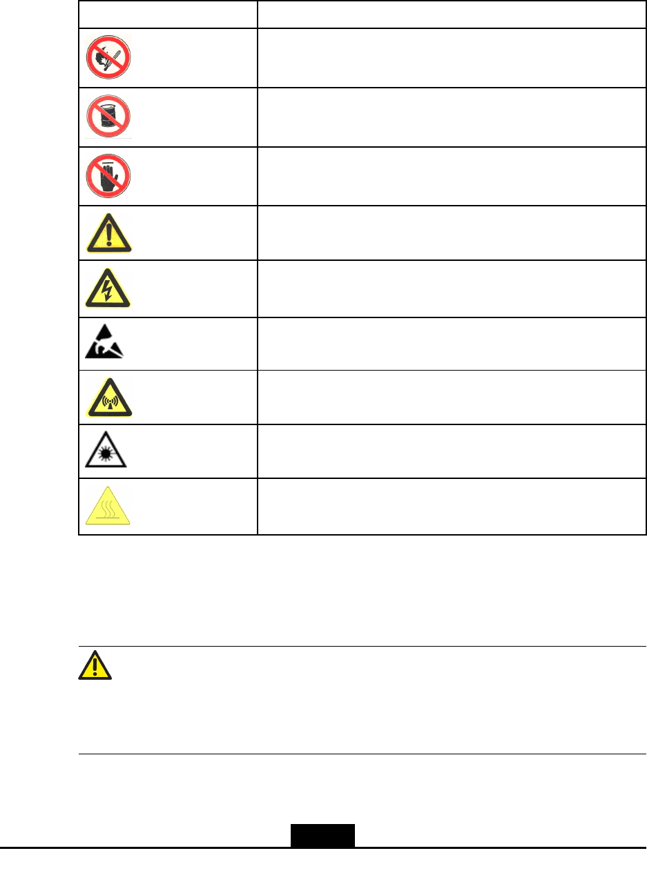
SafetySymbols
Table4-1listssafetysymbols.Theyaretoprompttheuserofthesafetyprecautionstobe
observedduringZXSDRRSU60Eoperationandmaintenance.
Table4-1SafetySymbolsDescription
SafetySymbolsMeaning
Nosmoking:Smokingisforbidden
Noammables:Noammablescanbestored.
Notouching:Donottouch.
Universalalertingsymbol:Generalsafetyattentions.
Electricshock:Riskofelectricshock.
Electrostatic:Thedevicemaybesensitivetostaticelectricity.
Microwave:Bewareofstrongelectromagneticeld.
Laser:Bewareofstronglaserbeam.
Scald:Bewareofscald.
Amongstthesesafetysymbols,theuniversalalarmsymbolsareclassiedintothreelevels:
danger,warning,andcaution.Theformatsandmeaningsofthethreelevelsaredescribed
asbelow:
Danger!
Indicatesapotentiallyhazardoussituationwhich,ifnotavoided,willresultindeathor
seriousinjuryofpeople,orequipmentdamagesandbreakdown.
4-3
SJ-20110823164828-001|2011–08–16ZTEProprietaryandCondential
ZXSDRRSU60EUserManual
Warning!
Indicatesapotentiallyhazardoussituationwhich,ifnotavoided,couldresultindeathor
seriousinjury.
Caution!
Indicatesapotentiallyhazardoussituationwhich,ifnotavoided,couldresultinserious
injuries,equipmentdamagesorinterruptionofpartservices.
4-4
SJ-20110823164828-001|2011–08–16ZTEProprietaryandCondential
SafetyInstructions
Thissectiondescribesthesafetyinstructionsrelatedtoelectricalsafety,antistatic,heavy
objectsandmodules.
ElectricalSafetyInstructions
Thefollowingaretheelectricalsafetyinstructionsabouttools,highvoltage,powercables,
holesandlightning:
lTools
Usespecialtoolsratherthancommontoolsforhigh-voltageandACoperations.
lHighVoltage
Danger!
Highvoltageishazardous.Directorindirectcontactwithhighvoltageormainsupply
usingawetobjectcouldresultindeath.
àStrictlyfollowlocalsafetyrulestoinstallACpowerdevices.
àInstallationstaffmustbequaliedforperforminghigh-voltageandACoperations.
àDonotwearanywatch,handchain,bracelet,ringoranyotherconductiveobjects
duringsuchoperations.
àPreventmoisturefromaccumulatingontheequipmentduringoperationsina
dampenvironment.
lPowerCable
Warning!
Neverinstalloruninstallpowercableswhiletheyarelive.Otherwise,thepowercable,
whencontactingaconductor,mayresultinsparksorelectricarccausingareoreven
damagetoeyes.
àMakesureofshuttingoffpowersupplybeforeinstallingordisconnectingapower
cable.
àBeforeconnectingthepowercable,makesurethattheconnectingcableandits
labelareappropriatefortheactualinstallationrequirements.
lDrillingHoles
4-5
SJ-20110823164828-001|2011–08–16ZTEProprietaryandCondential
ZXSDRRSU60EUserManual
Warning!
Itisnotallowedtodrillchassisholeswithoutpermission.
àUnqualieddrillingcoulddamagewiringandcablesinsidethechassis.
Additionally,metalpiecesinsidethechassiscreatedbythedrillingcouldresult
inashortcircuit.Useinsulationprotectionglovesandrstmovecablesinsidea
chassisawaywhendrillingisnecessaryonachassis.
àProtecteyesduringdrillingasdustoryingdebrismaydamageeyes.
àCleananydebrisintimeafterdrilling.
lLightning
Danger!
Donotperformhigh-voltage,AC,irontowerormastoperationsinathunderstorm.
Thunderstormswouldgiverisetoastrongelectromagneticeldintheatmosphere.
Therefore,theequipmentmustbegroundedandprotectedintimeagainstlightning
strikes.
AntistaticSafetyInstructions
Caution!
Staticelectricityproducedbyhumanbodycandamagestatic-sensitivecomponentson
circuitboard,suchaslarge-scaleintegratedcircuits.
lFrictioncausedbyhumanbodyactivitiesistherootcauseofelectrostaticcharge
accumulation.Staticvoltagecarriedbyahumanbodyinadryenvironmentcanbe
upto30kV,andcanremainthereforalongtime.Anoperatorwithstaticelectricity
maydischargeelectricitythroughacomponentwhenhe/shetouchestheconductor
andcausingdamage.
lWearanantistaticwriststrap(theotherendofwriststrapmustbewellgrounded)
beforetouchingtheequipmentorholdingaplug-inboard,circuitboard,Integrated
Circuit(IC)chiporotherdevices,topreventhumanstaticelectricityfromdamaging
sensitivecomponents.
lTheantistaticwriststrapusedmustbesubjecttoregularcheck.Donotreplacethe
cableofanantistaticwriststrapwithanyothercables.
4-6
SJ-20110823164828-001|2011–08–16ZTEProprietaryandCondential
Chapter4RSU60E
lDonotcontactstatic-sensitivemoduleswithanyobjectthateasilygeneratesstatic
electricity.Forexample,frictionofpackagebag,transferboxandtransferbeltmade
frominsulationplasticmaycausestaticelectricityoncomponents.Dischargeofstatic
electricitymaydamagecomponentswhentheycontactahumanbodyortheground.
lModulesshouldonlycontactmaterialssuchasanantistaticbag.Keepmodulesin
antistaticbagsduringstorageandtransportation.
lDischargestaticelectricityofthetestdevicebeforeuse,thatis,groundthetestdevice
rst.
lDonotplacethemodulenearastrongDCmagneticeld,suchasthecathode-ray
tubeofamonitor.Keepthemoduleatleast10cmaway.
HoistingHeavyObjects
Warning!
Whenhoistingheavyobjects,ensurethatnobodyisstandingorwalkingunderthehoisted
object.
lEnsurethehoistercanmeethoistingrequirementswhendisassemblingheavy
equipment,ormovingandreplacingequipment.
lTheinstallationpersonnelmustbedulytrainedandqualiedforhoistingoperations.
lHoistingtoolsmustbeinspectedandcompletebeforeservice.
lMakesurethathoistingtoolsarexedrmlyonasufcientlysecuredobjectorwall
beforethehoistingoperation.
lGivebrieforalinstructionsduringhoistingoperationstopreventanymishap.
Unplugging/PluggingaModule
lNeverplugamodulewithexcessiveforce,toensurethatthepinsonthebackplane
donotgetdeformed.
lPlugthemodulerightintotheslotandmakesuremodulecircuitfacesdonotcontact
eachotherlestanyshortcircuitmayoccur.
lKeephandsoffthemodulecircuit,components,connectorsandcabletroughwhen
holdingamodule.
RackMountSafetyInstructions
RackMountInstructions-Thefollowingorsimilarrack-mountinstructionsareincluded
withtheinstallationinstructions:
lElevatedOperatingAmbient-Ifinstalledinaclosedormulti-unitrackassembly,the
operatingambienttemperatureoftherackenvironmentmaybegreaterthanroom
ambient.Therefore,considerationshouldbegiventoinstallingtheequipmentinan
environmentcompatiblewiththemaximumambienttemperature(Tma)speciedby
themanufacturer.
4-7
SJ-20110823164828-001|2011–08–16ZTEProprietaryandCondential
ZXSDRRSU60EUserManual
lReducedAirFlow-Installationoftheequipmentinarackshouldbesuchthatthe
amountofairowrequiredforsafeoperationoftheequipmentisnotcompromised.
lMechanicalLoading-Mountingoftheequipmentintherackshouldbesuchthata
hazardousconditionisnotachievedduetounevenmechanicalloading.
lCircuitOverloading-Considerationshouldbegiventotheconnectionofthe
equipmenttothesupplycircuitandtheeffectthatoverloadingofthecircuitsmight
haveonovercurrentprotectionandsupplywiring.Appropriateconsiderationof
equipmentnameplateratingsshouldbeusedwhenaddressingthisconcern.
lReliableEarthing-Reliableearthingofrack-mountedequipmentshouldbe
maintained.Particularattentionshouldbegiventosupplyconnectionsotherthan
directconnectionstothebranchcircuit(e.g.useofpowerstrips).
OtherSafetyInstructions
Note:
Donotperformmaintenanceordebuggingindependently,unlessaqualiedpersonis
present.
lPerformanairtighttestbeforeRRUdelivery,andprohibitdisassemblingtheRRUon
site.
lReplacinganypartsormakinganychangestotheequipmentmightresultinan
unexpecteddanger.Therefore,besurenottoreplaceanypartsorperformany
changestotheequipmentunlessauthorizedotherwise.
lDuetothatRRUisinhightemperatureduringrunning,theRRUshouldbeinstalled
insomeregionsoutofoperators'reachorstrictlyrestricted.
lContactZTEofceifyouhaveanyquestion,toensureyoursafety.
4-8
SJ-20110823164828-001|2011–08–16ZTEProprietaryandCondential
Chapter4RSU60E
4.2ProductDescripition
4.2.1Overview
ZTESoftwareDenedRadio(SDR)usesanarchitectureofseparatingthebaseband
partfromtheRadioFrequency(RF)part.Thisarchitecturefeatureshighintegration,
lowconsumption,exiblecongurationandconvenientinstallation&maintenance.The
newgenerationZTEGSM&UMTSBaseStation(BS)productsbasedontheSDRisthe
rstSDR-basedGSM&UMTSBSintheindustry.Itisabletohelptheoperatorshave
qualitativeleap.TheformofthisproductcanbedistributedBBU+RRUorBBU+RSU.
TheproductformofZTESDRcanbedistributedBBU+RRUorBBU+RSU,macroBS
ormicroBS.
ZXSDRRSU60EistheRSUpartofZTEGSM&UMTSdistributedSDRCommonBTS
PlatformSolution.ItprovidesfunctionsincludingRFmodulation/demodulation,forward
poweramplication,reverselownoiseamplication,RFperformancemeasurementand
carrierpowercontroletc.
Withasmallersizeandlighterweight,theZXSDRRSU60Ehassignicantadvantagesfor
savingspace,relocations,installationexibility,andpowersavings.Itdesignedforboth
indoorandoutdoorapplications.
4.2.2PositioninaNetwork
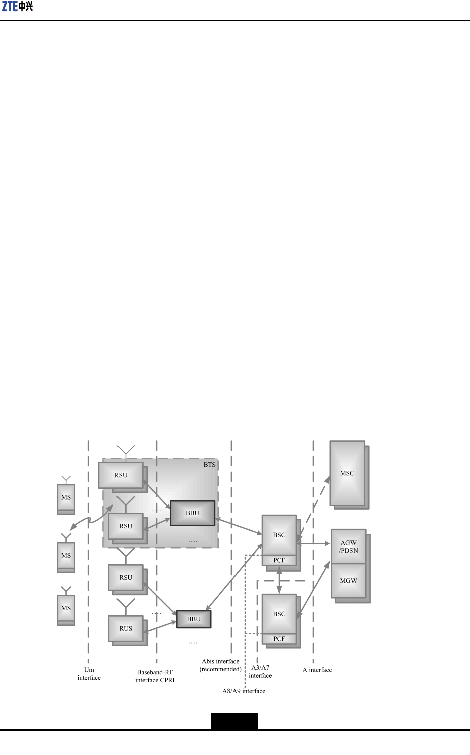
InGSM&UMTSmobilecommunicationnetwork,therelationshipbetweenZXSDR
RSU60EandothernetworkentitiesisshowninFigure4-1.
Figure4-1ZXSDRRSU60EPositioninaNetwork
4-9
SJ-20110823164828-001|2011–08–16ZTEProprietaryandCondential
ZXSDRRSU60EUserManual
TheZXSDRRSU60EisanindependentRFsubsystem.TogetherwithBBU,itformsthe
completeBTS.TheBTSimplementsradiotransmissionwiththeMSthroughtheUmair
interface.Inaddition,theBTSimplementscontrolofradiochannelsandcommunication
withtheBSC
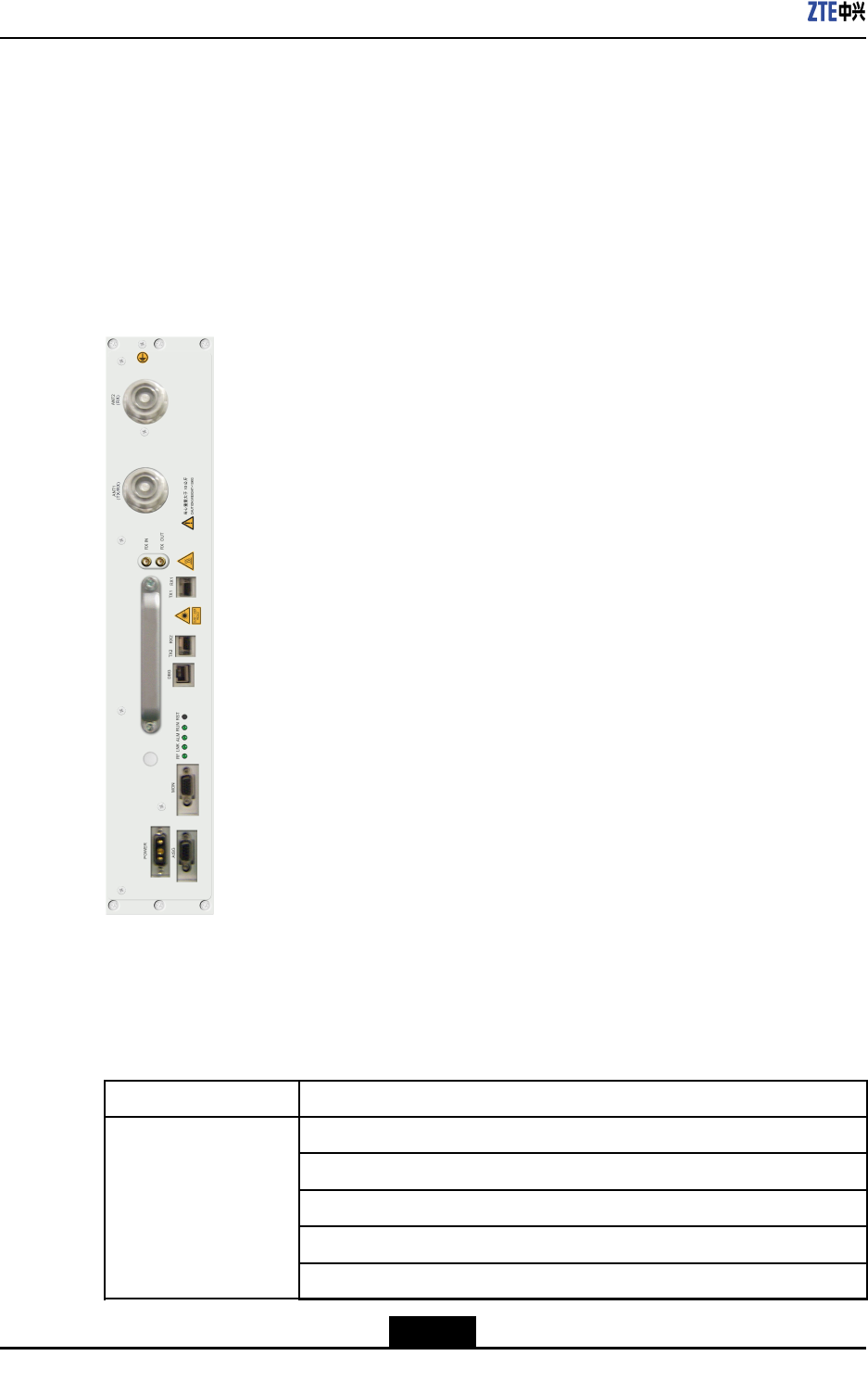
4.2.3OuterView
Figure4-2showstheouterviewofZXSDRRSU60E.
Figure4-2OuterViewofZXSDRRSU60E
4.2.4ProductionFunctions
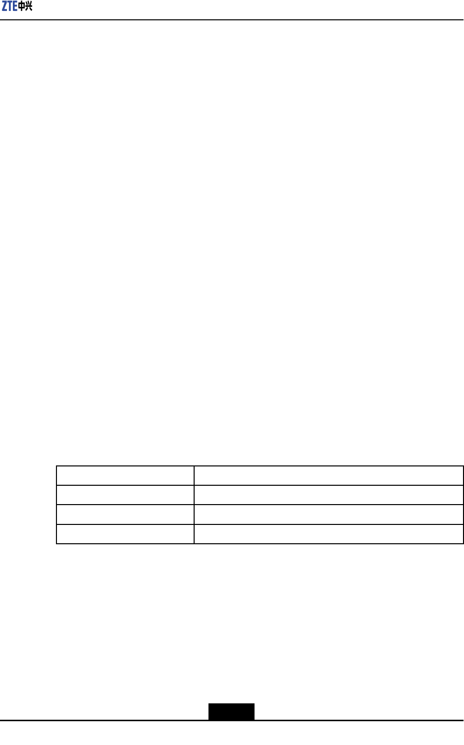
ZXSDRRSU60EprovidesprimaryfunctionsisshownasT able4-2.
Table4-2ThePrimaryFunctionsofZXSDRRSU60E
FunctionDescription
Band:850MHz
RFmodulation/demodulation
RFtransceiverduplexer
LownoiseamplicationforreceivedRFsignal
AmplicationfortransmittedRFsignal
RF
4-10
SJ-20110823164828-001|2011–08–16ZTEProprietaryandCondential
Chapter4RSU60E
FunctionDescription
RFtransceiver
InterfaceBaseband-RFinterface:compliantwithCommonPublicRadioInterface
(CPRI)protocol
Electroniclabel
RemoteupgradeofsoftwareversionforFPGA/BOOT/DSP/CPU
Remoteresetofserviceboards
Automaticcalibration
Reversespectrumquery:queryingthereversereceivedsignalspectrumof
eachcarrier
Equipment
maintenanceandtest
Poweramplicationcontrolandprotection:over-power,over-temperature,
andstandingwavealarm
ReliabilityReversevoltageprotection
ScenarioIndoorandoutdoorapplications
4.2.5ProductionFeatures
HerearetheproductfeaturesofZXSDRRSU60E
lEasytransportationandinstallationwillsavelaborandbuildingcosts
lLowerpowerconsumptionreducesinstallationofpowerexpendituresandsaveson
electricitycharges.
lSuitableforcomplicatedbasestationenvironments
SupportsstarandchainnetworksbetweenbasebandandRFtoprovidemore
convenientsolutionsforcomplicatedbasestationenvironments.
4.3TechnicalDescripition
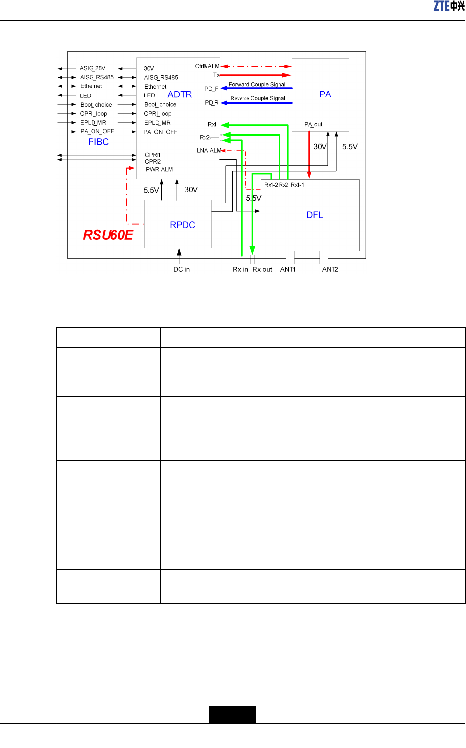
4.3.1SystemArchitecture
AZXSDRRSU60Econsistsofthetransmit/receivesignalboard(ADTR),poweramplier
(PA),duplexer(DFL),andpowersupply(RPDC).Figure4-3showstheschematicdiagram
oftheZXSDRRSU60E.
4-11
SJ-20110823164828-001|2011–08–16ZTEProprietaryandCondential
ZXSDRRSU60EUserManual
Figure4-3SchematicDiagramoftheZXSDRRSU60E
ThefunctionsofZXSDRRSU60E’ssubsystemisshownasTable4-3.
Table4-3Thefunctionsofsubsystem
PartDescription
ADTR
ADTR,theunitthatintegratestheprocessor,clock,CPRIinterface,DPD
digitalpredistortion,RFtransmittingandreceivingfunctions,isthecore
unitoftheZXSDRRSU60E.
PA
lAmpliesdownlinkRFsignalinputviatheADTRandthensendsthe
signaltotheDFL
lProvidesdigitalpre-distortionfeedbacksignalsfortheADTR
lProvidesaPAoutputenable/disableinterface
DFL
lPerformslteringandlownoiseamplicationofthereverse
GSM&UMTSsignalfromtheantenna
lFilterstheforwardRFsignaltobesent
lReportsLNAalarmstotheADTR
lInthecaseofmain/diversitycombinedcabinets,themainreceiveLNA
outputendoftheDFLhasthepowersplitterfunctionandreserves
anexternalport(Rxout)
RPDC
Converts-48VDCinputpowersupplytoDCpowersupplyrequiredby
thePA,ADTR,orDFL
4.3.2SignalProcessingFlow
TheinternalsignalprocessingowofZXSDRRSU60Eisasbelow:
lForwardlinkprocessing
4-12
SJ-20110823164828-001|2011–08–16ZTEProprietaryandCondential
Chapter4RSU60E
ThebusinessdatafromBBUenterstheADTR,andthenforintermediatefrequency
processing.Afterthepoweramplicationsenttotheantennafortransmission.
lReverselinkprocessing
ThereverseGSM&UMTSsignalsfromtheantennaareconvertedtobasebanddigital
signalbyADTR,thensendtoBBU.
4.3.3TechnicalSpecifications
4.3.3.1PhysicalIndices
4.3.3.1.1Dimension
ThedimensionsofZXSDRRSU60Einmmare:482.6(H)×88(W)×360.0(D).
4.3.3.1.2Weight
WeightofaZXSDRRSU60E:<15kg(33.1pounds).
4.3.3.2Power
lPowerSupply
-48VDCVoltagerange:-40V~-57V.
lPowerConsumption
Thetotalpowerconsumptionoftheequipmentis360W.
4.3.3.3CapacityIndices
ZXSDRRSU60ECapacityIndicesisshownasTable4-4
Table4-4ZXSDRRSU60ECapacityIndices
ItemCarrierssupported
1GSM6C(maxSingleRAT)
2UMTS3C(maxSingleRAT)
32GMS+2UMTS;4GSM+1UMTS
4.3.3.4TemperatureandHumidity
Temperature:-5℃~+45℃.Thechangefrequencymustbelessthan0.5℃/min.
Relativehumidity:5%~95%
4.3.3.5ReliabilityIndices
lMeanTimeBetweenFailures(MTBF):>100,000hours
lMTTR(MeanTimeT oRepair):<0.5hour
4-13
SJ-20110823164828-001|2011–08–16ZTEProprietaryandCondential
ZXSDRRSU60EUserManual
lAvailability:>99.999%
4.3.3.6RFIndices
RFindicesoftheZXSDRRSU60Ecomplywith3GPPTS51.021,RecommendedMinimum
PerformanceStandardsand3GPPTS25.141,RecommendedMinimumPerformance
Standards.
Table4-5illustratestheTechnicalSpecicationsofRSU60E.
Table4-5TheTechnicalSpecicationsofRSU60E
BandGSM850TX:869MHz~894MHzRX:824MHz~849MHz
channelrasteris200kHz
OutputpowerattheTopofCabinet(TOC)80W
TotaltransmitpowerThetotaltransmitpoweriswithin+2dBand-2
dBoftheManufacturer’sratedpower.
ModulationmodeGMSK\8PSK\QPSK\16QAM\64QAM
4.3.3.7InterfaceIndices
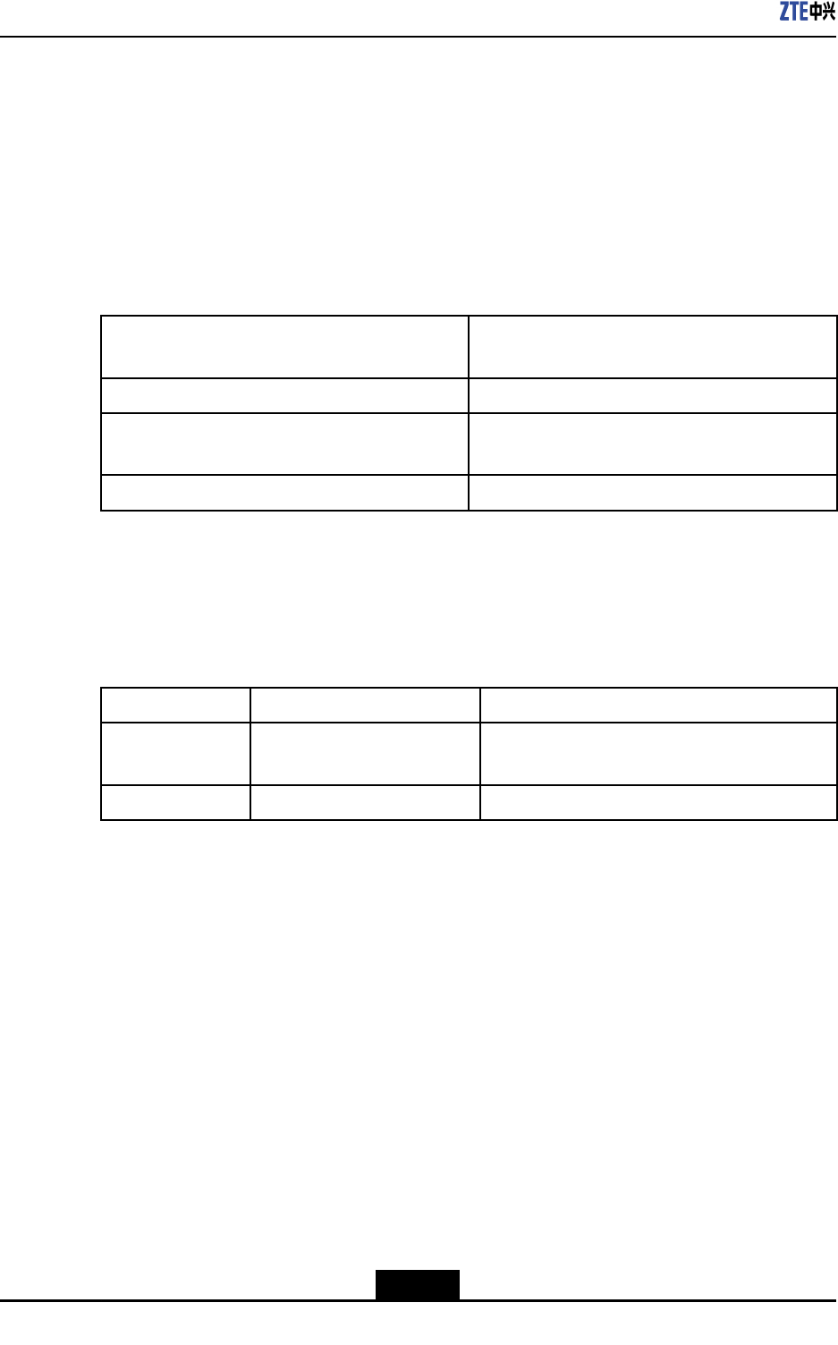
TheinterfaceindicesofZXSDRRSU60EisshownasTable4-6.
Table4-6DescriptionofZXSDRRSU60E’sinterfaces
TypeDescriptionIndex
CPRIFiber/Cable2CPRIinterfaces:1CPRIforBBUor
upper-levelRSU1CPRIforlower-levelRSU
UEUminterface1Tx/Rx1diversityreceivers
4.4HardwareDecsripition
4.4.1Function
RSUprovidesthefollowingfunctions:
lCommunicationwiththebasebandsubrack
lConversionbetweenairinterfaceRFsignalsanddigitalsignals
lRFsignalamplication,transmission,andreception
lClocksynchronization.
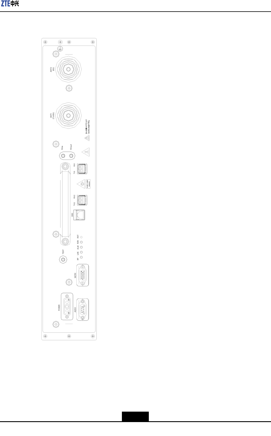
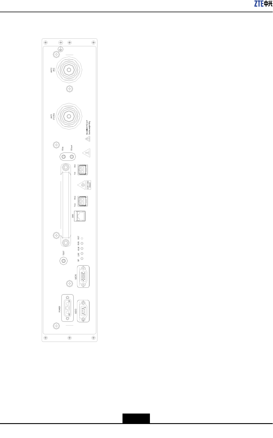
4.4.2Panel
Figure4-4illustratestheZXSDRRSU60Epanel.
4-14
SJ-20110823164828-001|2011–08–16ZTEProprietaryandCondential
ZXSDRRSU60EUserManual
Table4-7ZXSDRRSU60EPanelButtonDescription
ButtonDescription
RSTResetbutton
4.4.4Indicators
Table4-8describesZXSDRRSU60Epanelindicators.
Table4-8ZXSDRRSU60EPanelIndicatorDescription
IndicatorColorMeaningDescription
RUNGreenRunningstatus
indicator
Alwayson:TheRSUisresettingorstartingup.
Blinkingat1Hz:TheRSUisfunctioningproperly.
Blinkingat5Hz:TheRSUisdownloadingversion
les.
Off:TheRSUfailstheself-check.
ALMRedAlarmindicatorOff:ThereisonalarmortheRSUisresetting,
startingup,ordownloadingversionles.
Blinkingat5Hz:Thereisacriticalalarm.
Blinkingat1Hz:Thereisaminoralarm.
LNKGreenOpticallinkstatus
indicator
Alwayson:Theopticalconnectionisnormal.
Off:Theopticalberfails.
Blinkingat5Hz:Thislinkisusedastheclock
referencesourceandthephaselockloop(PLL)is
inthefastcapturestate.
Blinkingat0.25Hz:Thislinkisusedastheclock
referencesourceandthephaselockloop(PLL)is
inthetracingstate.
RFOrangeRFworking
statusindicator
Off:TheRFhasnooutput.
On:TheRFhasoutput.
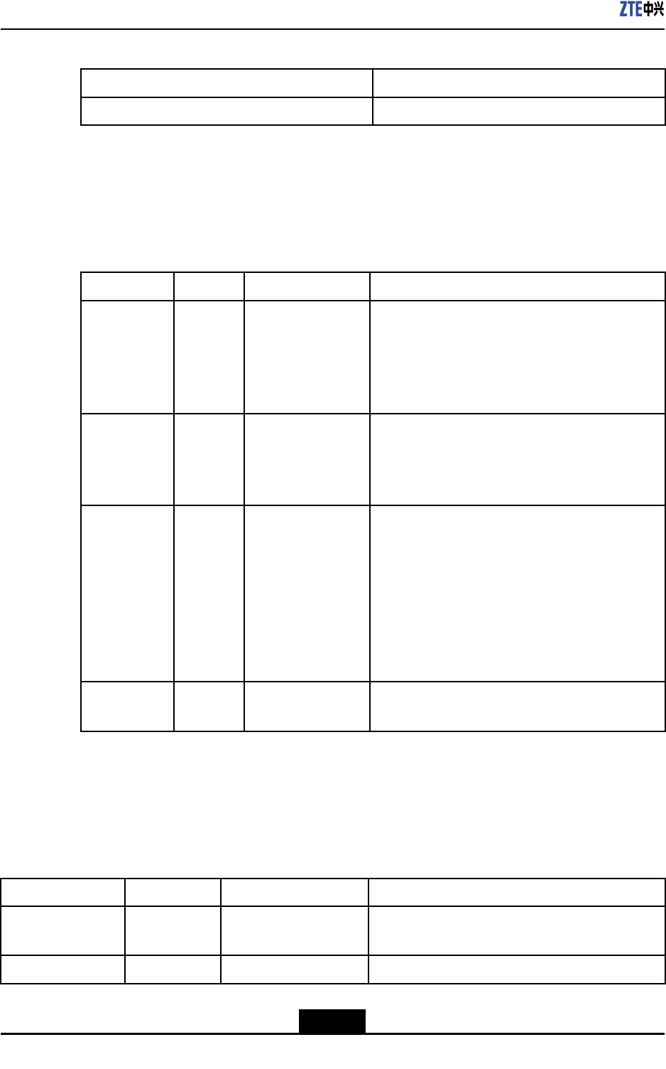
4.4.5PanelInterfaces
Table4-9describesZXSDRRSU60Epanelinterfaces.
Table4-9InterfacesontheFrontPaneloftheZXSDRRSU60E
InterfaceEndAEndBDescription
ANT1(TX/RX)RSUTx/RxantennaConnectstotheTx/RxantennafortheTx/Rx
majorchannel.
ANT2(RX)RSURxantennaConnectstotheantennalfortheRxminorantenna
4-16
SJ-20110823164828-001|2011–08–16ZTEProprietaryandCondential

Chapter4RSU60E
InterfaceEndAEndBDescription
RxoutRSURSUwithexpanded
frequencypoints
Frequency-pointexpansionoutputinterfacefor
outputtingtheRxsignalsofthemajorchannel.
RxinRSUwith
expanded
frequency
points
RSUFrequency-pointexpansioninputinterfacefor
inputtingtheRxsignalsoftheminorchannel.
TX1/RX1RSUBBUortheupper-layer
cascadedRSU
ConnectstotheCPRIopticalinterfaceofBBUor
theupper-layercascadedRSU
TX2/RX2RSULower-layercascaded
RSU
ConnectstotheCPRIopticalinterfaceofthe
lower-layercascadedRSU
DBGRSUPCortestingequipment
(withathetesting
board)
CommissioningEthernetinterfaceandtesting
interface
MONRSUExternalequipmentProvidesfourdry-contactinputinterfacesand
RS-485environmentmonitoringinterface
AISGRSUAntennaConnectstotheAISGinterface
POWERRSURFpowerofthepower
distributionmodule
Powerinputinterface
4.5HardwareInstallation
4.5.1InstallingtheRSUModule
Prerequisites
lBeforeinstallingtheRFmodule,weartheESDwriststraptoavoiddamagingtheRF
module.
lTheRFcabinethasalreadybeeninstalled.
Context
Figure4-5showsthefrontpanelofaZXSDRRSU60E.
4-17
SJ-20110823164828-001|2011–08–16ZTEProprietaryandCondential
ZXSDRRSU60EUserManual
Figure4-5ZXSDRRSU60EPanel
Steps
1.Determinethetargetslot,holdthehandleofthemodulewithonehand,supportthe
lowerbackofthemodulewiththeotherhand,andtrytomakeparallelthemoduleand
theguidingplane.
4-18
SJ-20110823164828-001|2011–08–16ZTEProprietaryandCondential
Chapter4RSU60E
2.Pushthemoduleslightlyintotheslottomorethanhalfthedepthoftheslot.
3.Changetheplacewhereexerciseforceandthenpushfurtherthemodulewitheven
force.
4.Pushthemoduleuntiltheinnersideofthefrontpanelcloselytouchtheverticalshaft.
5.SecurethemoduleusingveM5x20screws.
6.Securethegroundlug.
–EndofSteps–
Follow-UpAction
AfterinstallingRSUmodules,connecttheRSUpowercablestotheRSUpower
interfaces.RSUpowercableshavebeenroutedtoproperslots.
4.5.2ConnectingRSUMonitoringCable
Prerequisites
lZXSDRRSU60ERFcabinethasalreadybeeninstalled.
lTheRSUmodulehasalreadybeeninstalled.
Context
TheRSUmonitoringcableoftheRFcabinetisroutedtotherightsideoftheRFcabinet
indelivery.AftertheRSUmoduleisinstalled,inserttheterminaloftheRSUmonitoring
cabletotheMON(monitoring)interfaceoftheRSUmodule.
Note:
IfmultipleRSUmodulesneedtobemonitored,onlyoneRSUmoduleneedstobe
connectedtotheRSUmonitoringcable.
Steps
1.ConnectoneendoftheRSUmonitoringcabletotheMON(monitoring)interfaceof
theRSUmoduleandfastenthescrew.
2.BundletheRSUmonitoringcable.
–EndofSteps–
4-19
SJ-20110823164828-001|2011–08–16ZTEProprietaryandCondential
ZXSDRRSU60EUserManual
4.5.3InstallingOpticalFibersBetweenBBUandRSU
Prerequisites
lTheESDwriststrapmustbeworn.
lThebasebandpowercabinetandtheRFcabinethavebeenindependentlyinstalled.
Context
WhenthebasebandpowercabinetandtheRFcabinetareinstalledsidebysideorthey
arefarawayfromeachother,youneedtoconnectBBUandRSUusingopticalbers.
Payattentiontothefollowingpointswheninstallingopticalbers:
lDonotdamagetheopticalbercladdingduringoperations.
lProtectopticalberconnectorsandavoidcontaminatingthem.
lDonotforciblybundleopticalbers.
lCurveopticalbersattheturning.
Steps
1.Afxatemporarylabel.
Afxtemporarylabelstobothendsofthenewopticalbertosetupamapping.If
morethanoneopticalberneedstobeinstalled,usedifferentlabelstodifferentiate
opticalbers.
2.Routeopticalbers.
a.Opticalbersgooutfromthesidewaterproofmoduleofthebasebandmoduleand
gothroughtheroutingaperturesonthebase.
b.Then,opticalbersgothroughtheroutingaperturesonthebaseoftheRFcabinet,
traversethewaterproofmodules,andconnecttothesixopticalinterfacesforRF
modules.
3.Insertopticalberconnectors.
Insertopticalberconnectorsaccordingtothemappingontemporarylabels.
Caution!
Insertopticalberconnectorstightly.
4.Bundleopticalbers.
Bundleandsecureopticalbersalongtheroutingtroughs,whichcomplieswith
relevantregulations.
5.Afxanengineeringlabeltoanopticalber.
Removethetemporarylabelfortheopticalberandafxanengineeringlabel.
4-20
SJ-20110823164828-001|2011–08–16ZTEProprietaryandCondential
Chapter4RSU60E
Caution!
Protectanopticalberwiththewindingtubewhenroutingtheopticalberinsidethe
cabinet.Protectanopticalberwiththecorrugatedpipewhenroutingtheopticalber
outsidethecabinet.
–EndofSteps–
4.5.4InstallingtheInterconnectedCableBetweenBBUandRSU
Prerequisites
lTheZXSDRRSU60Ecabinethasalreadybeeninstalled.
lTheBBUmoduleandRSUmodulehavealreadybeeninstalled.
Context
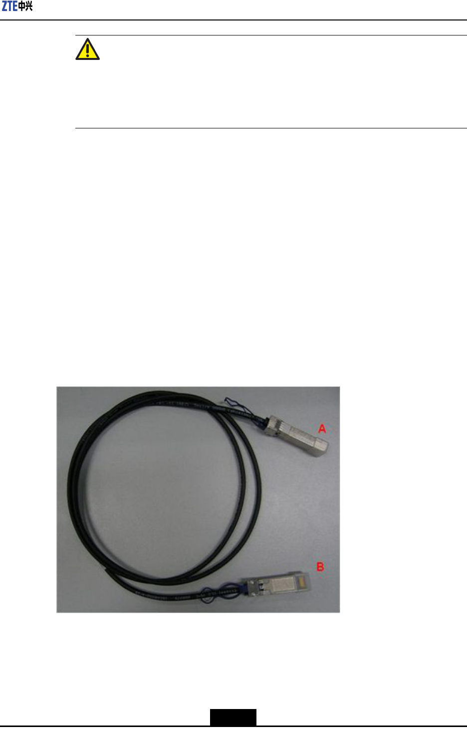
ZXSDRRSU60EInthesystem,opticalbersorSFPcablescanbeusedtoconnectBBU
andRSU.DuringthestackedinstallationoftheZXSDRRSU60E,a2mSFPhigh-speed
cableisrecommendedforinterconnectingBBUandRSU.Figure4-6showsanSFPcable.
Figure4-6High-SpeedCable
Steps
1.AfxtemporarylabelstobothendsoftheSFRcable,withmarkings0-5tosetup
one-to-onemappingwithinterfacesTX0RX0toTX5RX5ofBBUandsixTX/RX
interfacesofRSU.
4-21
SJ-20110823164828-001|2011–08–16ZTEProprietaryandCondential
ZXSDRRSU60EUserManual
2.InsertoneendoftheSFPcabletoaTX/RXinterfaceofRSU.
3.RoutetheSFPcablealongtheroutingtroughandcabinetsidestotheFSmoduleof
BBU.TheSFPcablesconnectingtotheRSUsinslots1to3ontheRFcabinetgo
throughtheleftroutingaperturesandthoseSFPcablesgothroughtherightapertures
ifconnectingtoslots4to6ontheRFcabinet.
4.InsertSFPcablesintotheinterfacesTX0RX0toTX5RX5oftheBBUFSboard
accordingtothemarkings0-5.
5.BundleSFPcables.
6.Removetemporarylabelsandafxengineeringlabels.
–EndofSteps–
4.5.5InstallingtheRFJumper
Prerequisites
TheZXSDRRSU60ERFcabinetandothermoduleshavealreadybeeninstalled.
Context
TheRFjumpersforthethreeZXSDRRSU60Egothroughthewaterproofmoduleonthe
right.
RemovethefrontbafeofthebasebeforeinstallingtheRFjumpersandreseatthefront
bafeafteralljumpersarecompletelyinstalled.
Steps
1.ConnecttheRFjumperstoANT1andANT2interfacesofRSUfromlefttoright.
2.WearthewaterproofrubberplugaftereverytwoRFjumpersareinstalled.
3.Insertthehorizontalandlongitudinalslideblocksandusethehexagonringwrenchto
fastenthem.
Caution!
Clampthewaterproofrubberplugtightlyandmakesurethattheunusedcabling
aperturewearstheplug.
4.RepeattheprecedingstepstoinstallotherRSU-relatedjumpers.
–EndofSteps–
4-22
SJ-20110823164828-001|2011–08–16ZTEProprietaryandCondential

Chapter4RSU60E
Result
TheRFjumpersgooutfromthebase.Thecablesbetweencabinetsmustbeprotected
withprotectivetubes,withoutanyexposedpartofthecablesandtheopeningsattwoends
ofthesecablesmustbesealed.
4-23
SJ-20110823164828-001|2011–08–16ZTEProprietaryandCondential

ZXSDRRSU60EUserManual
Thispageintentionallyleftblank.
4-24
SJ-20110823164828-001|2011–08–16ZTEProprietaryandCondential

Figures
Figure4-1ZXSDRRSU60EPositioninaNetwork....................................................4-9
Figure4-2OuterViewofZXSDRRSU60E.............................................................4-10
Figure4-3SchematicDiagramoftheZXSDRRSU60E..........................................4-12
Figure4-4ZXSDRRSU60EPanel..........................................................................4-15
Figure4-5ZXSDRRSU60EPanel..........................................................................4-18
Figure4-6High-SpeedCable.................................................................................4-21
I

Figures
Thispageintentionallyleftblank.

Tables
Table4-1SafetySymbolsDescription.......................................................................4-3
Table4-2ThePrimaryFunctionsofZXSDRRSU60E.............................................4-10
Table4-3Thefunctionsofsubsystem.....................................................................4-12
Table4-4ZXSDRRSU60ECapacityIndices...........................................................4-13
Table4-5TheTechnicalSpecicationsofRSU60E.................................................4-14
Table4-6DescriptionofZXSDRRSU60E’sinterfaces............................................4-14
Table4-7ZXSDRRSU60EPanelButtonDescription..............................................4-16
Table4-8ZXSDRRSU60EPanelIndicatorDescription..........................................4-16
Table4-9InterfacesontheFrontPaneloftheZXSDRRSU60E.............................4-16
III

Tables
Thispageintentionallyleftblank.

Glossary
BBU
-BaseBandUnit
BS
-BaseStation
BSC
-BaseStationController
BTS
-BaseTransceiverStation
CPRI
-CommonPublicRadioInterface
MS
-MobileStation
RF
-RadioFrequency
RSSI
-ReceivedSignalStrengthIndicator
RSU
-RFSystemUnit
SDR
-SoftwareDenedRadio
V