ZTE RSUC1930 CDMA Remote Radio Unit User Manual
ZTE Corporation CDMA Remote Radio Unit Users Manual
ZTE >
Users Manual

ZXSDRRSUC
RadioSystemUnitofCDMAwith1T2R
UserManual
VersionV1.00
ZTECORPORATION
NO.55,Hi-techRoadSouth,ShenZhen,P .R.China
Postcode:518057
Tel:(86)75526771900
Fax:(86)75526770801
URL:http://ensupport.zte.com.cn
E-mail:support@zte.com.cn

LEGALINFORMATION
Copyright©2010ZTECORPORATION.
Thecontentsofthisdocumentareprotectedbycopyrightlawsandinternationaltreaties.Anyreproductionordistributionof
thisdocumentoranyportionofthisdocument,inanyformbyanymeans,withoutthepriorwrittenconsentofZTECORPO-
RATIONisprohibited.Additionally,thecontentsofthisdocumentareprotectedbycontractualcondentialityobligations.
Allcompany,brandandproductnamesaretradeorservicemarks,orregisteredtradeorservicemarks,ofZTECORPORATION
oroftheirrespectiveowners.
Thisdocumentisprovided“asis”,andallexpress,implied,orstatutorywarranties,representationsorconditionsaredis-
claimed,includingwithoutlimitationanyimpliedwarrantyofmerchantability,tnessforaparticularpurpose,titleornon-in-
fringement.ZTECORPORATIONanditslicensorsshallnotbeliablefordamagesresultingfromtheuseoforrelianceonthe
informationcontainedherein.
ZTECORPORATIONoritslicensorsmayhavecurrentorpendingintellectualpropertyrightsorapplicationscoveringthesubject
matterofthisdocument.ExceptasexpresslyprovidedinanywrittenlicensebetweenZTECORPORATIONanditslicensee,
theuserofthisdocumentshallnotacquireanylicensetothesubjectmatterherein.
ZTECORPORATIONreservestherighttoupgradeormaketechnicalchangetothisproductwithoutfurthernotice.
UsersmayvisitZTEtechnicalsupportwebsitehttp://ensupport.zte.com.cntoinquirerelatedinformation.
TheultimaterighttointerpretthisproductresidesinZTECORPORATION.
RevisionHistory
RevisionNo.RevisionDateRevisionReason
25/10/201025/05/2010R1.0
SerialNumber:SJ-20101019140047-002

FCC&ICSTATEMENT
ThisdevicecomplieswithPart15oftheFCCRules.Operation
issubjecttothefollowingtwoconditions:(1)thisdevicemay
notcauseharmfulinterference,and(2)thisdevicemustaccept
anyinterferencereceived,includinginterferencethatmaycause
undesiredoperation.
Note:
Thisequipmenthasbeentestedandfoundtocomplywiththelim-
itsforaClassAdigitaldevice,pursuanttoPart15oftheFCC
Rules.Theselimitsaredesignedtoprovidereasonableprotection
againstharmfulinterferencewhentheequipmentisoperatedin
acommercialenvironment.Thisequipmentgenerates,uses,and
canradiateradiofrequencyenergyand,ifnotinstalledandused
inaccordancewiththeinstructionmanual,maycauseharmfulin-
terferencetoradiocommunications.
Operationofthisequipmentinaresidentialareaislikelytocause
harmfulinterferenceinwhichcasetheuserwillberequiredto
correcttheinterferenceathisownexpense.
CondentialandProprietaryInformationofZTECORPORATIONI

ZXSDRRSUCUserManual
Thispageisintentionallyblank.
IICondentialandProprietaryInformationofZTECORPORATION

DeclarationofRoHS
Compliance
Tominimizetheenvironmentalimpactandtakemoreresponsibility
totheearthwelive,thisdocumentshallserveasformaldeclara-
tionthatZXSDRRSUCmanufacturedbyZTECORPORATIONarein
compliancewiththeDirective2002/95/ECoftheEuropeanParlia-
ment-RoHS(RestrictionofHazardousSubstances)withrespect
tothefollowingsubstances:
�Lead(Pb)
�Mercury(Hg)
�Cadmium(Cd)
�HexavalentChromium(Cr(VI))
�PolyBrominatedBiphenyls(PBB’s)
�PolyBrominatedDiphenylEthers(PBDE’s)
…
TheZXSDRRSUCmanufacturedbyZTECORPORATIONmeet
therequirementsofEU2002/95/EC;however ,someassemblies
arecustomizedtoclientspecications.Additionofspecialized,
customer-speciedmaterialsorprocesseswhichdonotmeetthe
requirementsofEU2002/95/ECmaynegateRoHScomplianceofthe
assembly.Toguaranteecomplianceoftheassembly,theneedfor
compliantproductmustbecommunicatedtoZTECORPORATIONin
writtenform.Thisdeclarationisissuedbasedonourcurrentlevel
ofknowledge.Sinceconditionsofuseareoutsideourcontrol,ZTE
CORPORATIONmakesnowarranties,expressorimplied,andassumes
noliabilityinconnectionwiththeuseofthisinformation.
CondentialandProprietaryInformationofZTECORPORATIONI

ZXSDRRSUCUserManual
Thispageisintentionallyblank.
IICondentialandProprietaryInformationofZTECORPORATION

Chapter1
SafetyDescription
TableofContents
SafetySpecicationsGuide.................................................1
SafetySymbols.................................................................2
SafetyInstructions............................................................3
SafetySpecificationsGuide
Thesesafetyinstructionsmustbeconsideredassupplementaryfor
localsafetyregulations.Theprioritymustbegiventolocalsafety
regulationsifthereisanyconictbetweenthetwo.
Themaintenancepersonnelmusthavetheknowledgeofsafety
operationsandmaintenancewithrequiredqualicationandtech-
nicalbackground.
Warning:
Thisdevicecomplieswithpart15oftheFCCRules.Operationis
subjecttothefollowingtwoconditions:
�Thisdevicemaynotcauseharmfulinterference.
�Thisdevicemustacceptanyinterferencereceived,including
interferencethatmaycauseundesiredoperation.
Changesormodicationsnotexpresslyapprovedbythepartyre-
sponsibleforcompliancecouldvoidtheuser'sauthoritytooperate
theequipment.
TheequipmentisintendedforinstallationinRESTRICTEDACCESS
LOCATIONS.
Alltheoperationandmaintenancepersonnelmustfollowthe
safetyprecautionsandinstructionsprovidedbyZTECorporation
toavoidanyaccident.
CondentialandProprietaryInformationofZTECORPORATION1
ZXSDRRSUCUserManual
Note:
ZTECorporationdoesnotbearanyliabilitiesincurredbecauseof
violationoftheuniversalsafetyoperationrequirements,orviola-
tionofsafetystandardsfordesigning,manufacturingandusing
theequipment.
FCCRadiationExposureStatement:
ThisequipmentcomplieswithFCCradiationexposurelimitsset
forthforanuncontrolledenvironment.Thisequipmentshouldbe
installedandoperatedwithminimumdistance4mbetweenthe
radiator&yourbody.
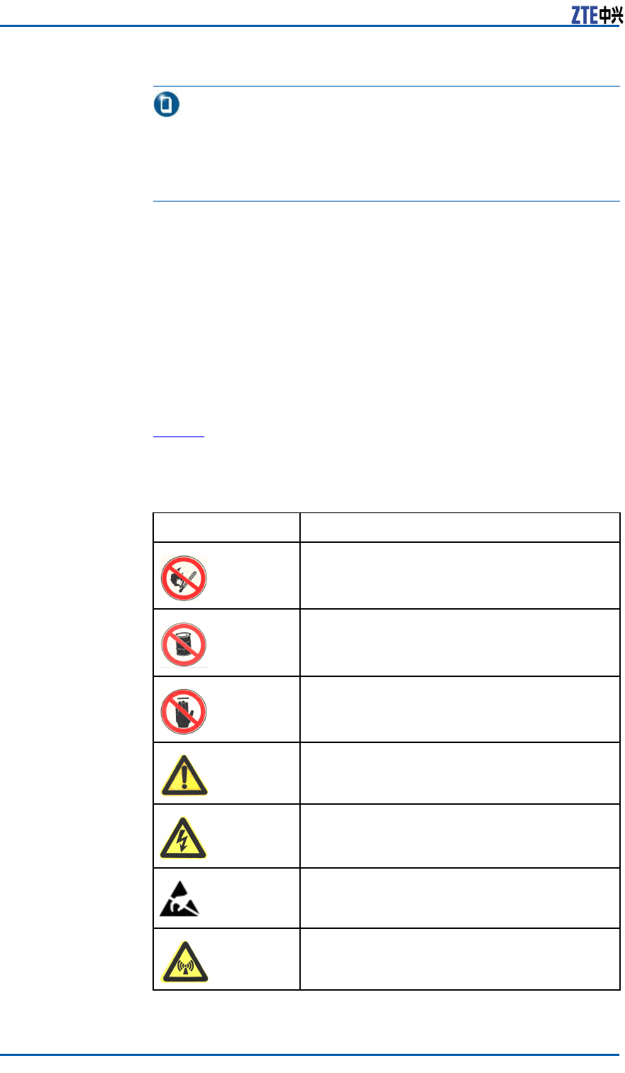
SafetySymbols
Table1listssafetysymbols.Theyaretoprompttheuserofthe
safetyprecautionstobeobservedduringZXSDRRSUCoperation
andmaintenance.
TABLE1SAFETYSYMBOLSDESCRIPTION
SafetySymbolsMeaning
Nosmoking:Smokingisforbidden
Noammables:Noammablescanbestored.
Notouching:Donottouch.
Universalalertingsymbol:Generalsafety
attentions.
Electricshock:Riskofelectricshock.
Electrostatic:Thedevicemaybesensitiveto
staticelectricity.
Microwave:Bewareofstrongelectromagnetic
eld.
2CondentialandProprietaryInformationofZTECORPORATION
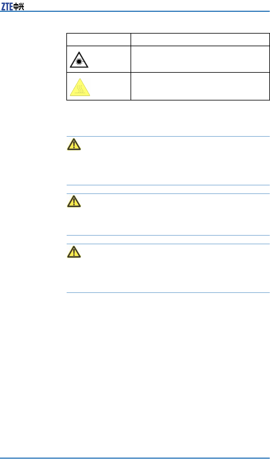
Chapter1SafetyDescription
SafetySymbolsMeaning
Laser:Bewareofstronglaserbeam.
Scald:Bewareofscald.
Amongstthesesafetysymbols,theuniversalalarmsymbolsare
classiedintothreelevels:danger ,warning,andcaution.The
formatsandmeaningsofthethreelevelsaredescribedasbelow:
Danger:
Indicatesapotentiallyhazardoussituationwhich,ifnotavoided,
willresultindeathorseriousinjuryofpeople,orequipmentdam-
agesandbreakdown.
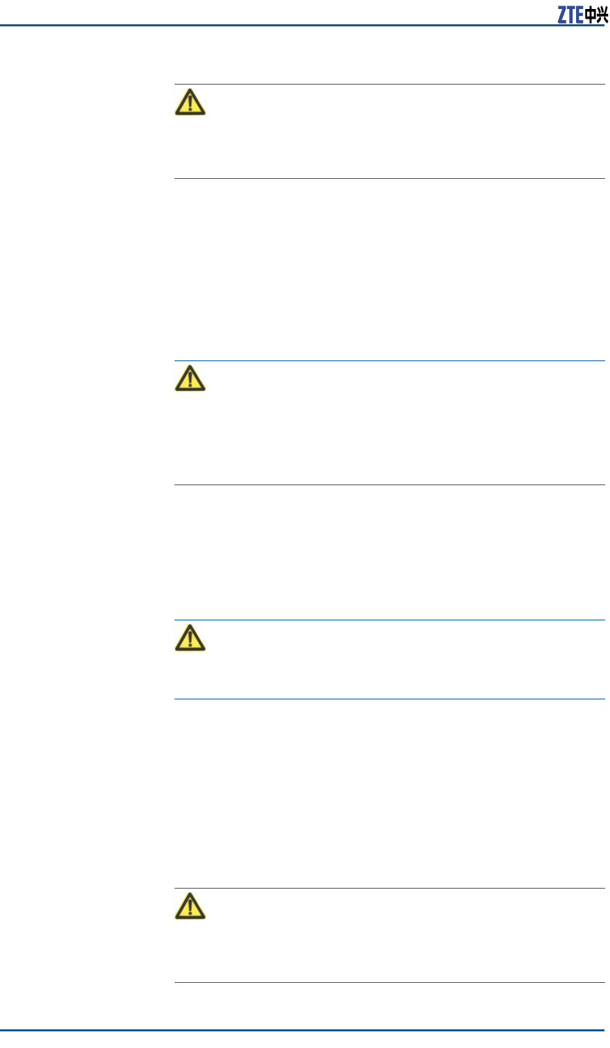
Warning:
Indicatesapotentiallyhazardoussituationwhich,ifnotavoided,
couldresultindeathorseriousinjury.
Caution:
Indicatesapotentiallyhazardoussituationwhich,ifnotavoided,
couldresultinseriousinjuries,equipmentdamagesorinterruption
ofpartservices.
SafetyInstructions
Thissectiondescribesthesafetyinstructionsrelatedtoelectrical
safety,antistatic,heavyobjectsandmodules.
ElectricalSafety
InstructionsThefollowingaretheelectricalsafetyinstructionsabouttools,high
voltage,powercables,holesandlightning:
�Tools
Usespecialtoolsratherthancommontoolsforhigh-voltage
andACoperations.
�HighVoltage
CondentialandProprietaryInformationofZTECORPORATION3
ZXSDRRSUCUserManual
Danger:
Highvoltageishazardous.Directorindirectcontactwithhigh
voltageormainsupplyusingawetobjectcouldresultindeath.
�StrictlyfollowlocalsafetyrulestoinstallACpowerdevices.
�Installationstaffmustbequaliedforperforminghigh-volt-
ageandACoperations.
�Donotwearanywatch,handchain,bracelet,ringorany
otherconductiveobjectsduringsuchoperations.
�Preventmoisturefromaccumulatingontheequipmentdur-
ingoperationsinadampenvironment.
�PowerCable
Warning:
Neverinstalloruninstallpowercableswhiletheyarelive.Oth-
erwise,thepowercable,whencontactingaconductor ,mayre-
sultinsparksorelectricarccausingareorevendamageto
eyes.
�Makesureofshuttingoffpowersupplybeforeinstallingor
disconnectingapowercable.
�Beforeconnectingthepowercable,makesurethatthecon-
nectingcableanditslabelareappropriatefortheactual
installationrequirements.
�DrillingHoles
Warning:
Itisnotallowedtodrillchassisholeswithoutpermission.
�Unqualieddrillingcoulddamagewiringandcablesinside
thechassis.Additionally,metalpiecesinsidethechassis
createdbythedrillingcouldresultinashortcircuit.Use
insulationprotectionglovesandrstmovecablesinsidea
chassisawaywhendrillingisnecessaryonachassis.
�Protecteyesduringdrillingasdustoryingdebrismay
damageeyes.
�Cleananydebrisintimeafterdrilling.
�Lightning
Danger:
Donotperformhigh-voltage,AC,irontowerormastoperations
inathunderstorm.
4CondentialandProprietaryInformationofZTECORPORATION
Chapter1SafetyDescription
Thunderstormswouldgiverisetoastrongelectromagnetic
eldintheatmosphere.Therefore,theequipmentmustbe
groundedandprotectedintimeagainstlightningstrikes.
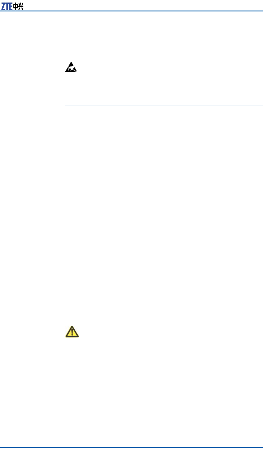
AntistaticSafety
InstructionsElectrostatic:
Staticelectricityproducedbyhumanbodycandamagestatic-sen-
sitivecomponentsoncircuitboard,suchaslarge-scaleintegrated
circuits.
�Frictioncausedbyhumanbodyactivitiesistherootcauseof
electrostaticchargeaccumulation.Staticvoltagecarriedbya
humanbodyinadryenvironmentcanbeupto30kV ,andcan
remainthereforalongtime.Anoperatorwithstaticelectricity
maydischargeelectricitythroughacomponentwhenhe/she
touchestheconductorandcausingdamage.
�Wearanantistaticwriststrap(theotherendofwriststrapmust
bewellgrounded)beforetouchingtheequipmentorholding
aplug-inboard,circuitboard,IntegratedCircuit(IC)chipor
otherdevices,topreventhumanstaticelectricityfromdamag-
ingsensitivecomponents.
�Theantistaticwriststrapusedmustbesubjecttoregular
check.Donotreplacethecableofanantistaticwriststrap
withanyothercables.
�Donotcontactstatic-sensitivemoduleswithanyobjectthat
easilygeneratesstaticelectricity.Forexample,frictionofpack-
agebag,transferboxandtransferbeltmadefrominsulation
plasticmaycausestaticelectricityoncomponents.Discharge
ofstaticelectricitymaydamagecomponentswhentheycon-
tactahumanbodyortheground.
�Modulesshouldonlycontactmaterialssuchasanantistatic
bag.Keepmodulesinantistaticbagsduringstorageandtrans-
portation.
�Dischargestaticelectricityofthetestdevicebeforeuse,that
is,groundthetestdevicerst.
�DonotplacethemodulenearastrongDCmagneticeld,such
asthecathode-raytubeofamonitor .Keepthemoduleatleast
10cmaway.
HoistingHeavy
ObjectsWarning:
Whenhoistingheavyobjects,ensurethatnobodyisstandingor
walkingunderthehoistedobject.
�Ensurethehoistercanmeethoistingrequirementswhendis-
assemblingheavyequipment,ormovingandreplacingequip-
ment.
�Theinstallationpersonnelmustbedulytrainedandqualied
forhoistingoperations.
�Hoistingtoolsmustbeinspectedandcompletebeforeservice.
CondentialandProprietaryInformationofZTECORPORATION5

ZXSDRRSUCUserManual
�Makesurethathoistingtoolsarexedrmlyonasufciently
securedobjectorwallbeforethehoistingoperation.
�Givebrieforalinstructionsduringhoistingoperationstopre-
ventanymishap.
Unplugging/Plug-
gingaModule�Neverplugamodulewithexcessiveforce,toensurethatthe
pinsonthebackplanedonotgetdeformed.
�Plugthemodulerightintotheslotandmakesuremodulecir-
cuitfacesdonotcontacteachotherlestanyshortcircuitmay
occur .
�Keephandsoffthemodulecircuit,components,connectors
andcabletroughwhenholdingamodule.
RackMountSafety
InstructionsRackMountInstructions-Thefollowingorsimilarrack-mountin-
structionsareincludedwiththeinstallationinstructions:
�ElevatedOperatingAmbient-Ifinstalledinaclosedormulti-
unitrackassembly,theoperatingambienttemperatureofthe
rackenvironmentmaybegreaterthanroomambient.There-
fore,considerationshouldbegiventoinstallingtheequipment
inanenvironmentcompatiblewiththemaximumambienttem-
perature(Tma)speciedbythemanufacturer .
�ReducedAirFlow-Installationoftheequipmentinarack
shouldbesuchthattheamountofairowrequiredforsafe
operationoftheequipmentisnotcompromised.
�MechanicalLoading-Mountingoftheequipmentintherack
shouldbesuchthatahazardousconditionisnotachieveddue
tounevenmechanicalloading.
�CircuitOverloading-Considerationshouldbegiventothecon-
nectionoftheequipmenttothesupplycircuitandtheeffect
thatoverloadingofthecircuitsmighthaveonovercurrentpro-
tectionandsupplywiring.Appropriateconsiderationofequip-
mentnameplateratingsshouldbeusedwhenaddressingthis
concern.
�ReliableEarthing-Reliableearthingofrack-mountedequip-
mentshouldbemaintained.Particularattentionshouldbe
giventosupplyconnectionsotherthandirectconnectionsto
thebranchcircuit(e.g.useofpowerstrips).
OtherSafety
InstructionsNote:
Donotperformmaintenanceordebuggingindependently,unless
aqualiedpersonispresent.
�PerformanairtighttestbeforeRRUdelivery,andprohibitdis-
assemblingtheRRUonsite.
�Replacinganypartsormakinganychangestotheequipment
mightresultinanunexpecteddanger .Therefore,besurenot
toreplaceanypartsorperformanychangestotheequipment
unlessauthorizedotherwise.
�DuetothatRRUisinhightemperatureduringrunning,theRRU
shouldbeinstalledinsomeregionsoutofoperators'reachor
strictlyrestricted.
6CondentialandProprietaryInformationofZTECORPORATION

Chapter1SafetyDescription
�ContactZTEofceifyouhaveanyquestion,toensureyour
safety.
CondentialandProprietaryInformationofZTECORPORATION7

ZXSDRRSUCUserManual
Thispageisintentionallyblank.
8CondentialandProprietaryInformationofZTECORPORATION

Chapter2
ProductDescripition
TableofContents
Overview..........................................................................9
PositioninaNetwork.........................................................9
OuterView.......................................................................10
ProductionFunctions..........................................................11
ProductionFeatures...........................................................12
Overview
ZTESoftwareDenedRadio(SDR)usesanarchitectureofseparat-
ingthebasebandpartfromtheRadioFrequency(RF)part.This
architecturefeatureshighintegration,lowconsumption,exible
congurationandconvenientinstallation&maintenance.Thenew
generationZTECDMABaseStation(BS)productsbasedonthe
SDRistherstSDR-basedCDMABSintheindustry.Itisableto
helptheoperatorshavequalitativeleap.Theformofthisproduct
canbedistributedBBU+RRUorBBU+RSU.Theproductformof
ZTESDRcanbedistributedBBU+RRUorBBU+RSU,macroBS
ormicroBS.
ZXSDRRSUCistheRSUpartofZTECDMA2000distributedSDR
CommonBTSPlatformSolution.ItprovidesfunctionsincludingRF
modulation/demodulation,forwardpoweramplication,reverse
lownoiseamplication,RFperformancemeasurementandcar-
rierpowercontroletc.
Withasmallersizeandlighterweight,theZXSDRRSUChassig-
nicantadvantagesforsavingspace,relocations,installationex-
ibility,andpowersavings.Itdesignedforbothindoorandoutdoor
applications.
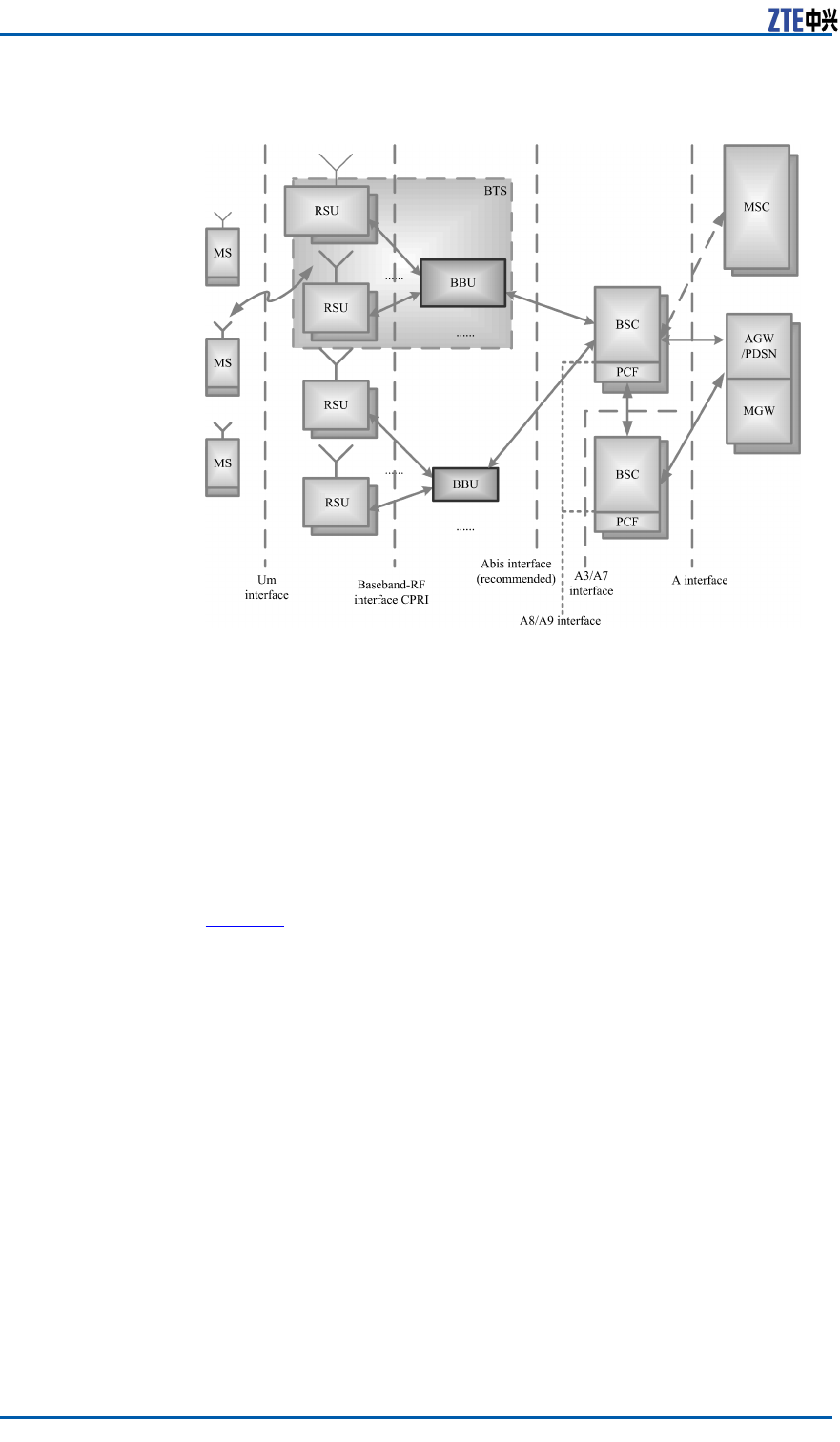
PositioninaNetwork
InCDMAmobilecommunicationnetwork,therelationshipbetween
ZXSDRRSUCandothernetworkentitiesisshowninFigure1.
CondentialandProprietaryInformationofZTECORPORATION9
ZXSDRRSUCUserManual
FIGURE1ZXSDRRSUCPOSITIONINANETWORK
TheZXSDRRSUCisanindependentRFsubsystem.Togetherwith
BBU,itformsthecompleteBTS.TheBTSimplementsradiotrans-
missionwiththeMSthroughtheCDMA2000airinterface.Inad-
dition,theBTSimplementscontrolofradiochannelsandcommu-
nicationwiththeBSC
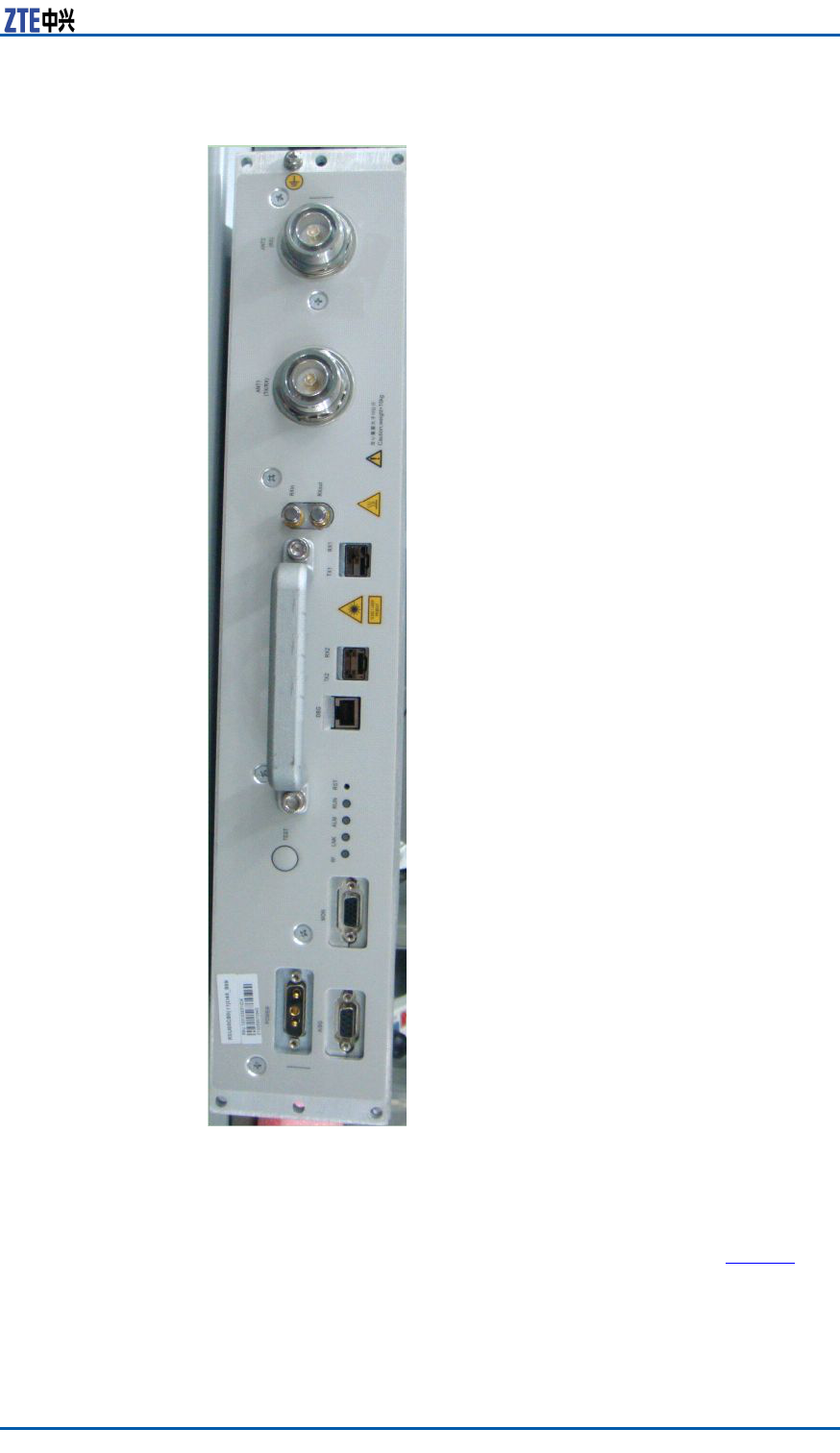
OuterView
Figure2showstheouterviewofZXSDRRSUC.
10CondentialandProprietaryInformationofZTECORPORATION

ZXSDRRSUCUserManual
TABLE2THEPRIMARYFUNCTIONSOFZXSDRRSUC
FunctionDescription
Band:800MHz、1.9GHz、2.1GHz、2.0GHz(AWS)、
450MHz、420MHz、850MHz
RFmodulation/demodulation
RFtransceiverduplexer
LownoiseamplicationforreceivedRFsignal
AmplicationfortransmittedRFsignal
RF
RFtransceiver
Baseband-RFinterface:compliantwithCommon
PublicRadioInterface(CPRI)protocol
Interface
Airinterface:compliantwithIS-2000ReleaseA
andIS-856-A
Electroniclabel
Remoteupgradeofsoftwareversionfor
FPGA/BOOT/DSP/CPU
Remoteresetofserviceboards
RSSIquery
Automaticcalibration
Reversespectrumquery:queryingthereverse
receivedsignalspectrumofeachcarrier
Equipment
maintenance
andtest
Poweramplicationcontrolandprotection:
over-power ,over-temperature,andstandingwave
alarm
ReliabilityReversevoltageprotection
ScenarioIndoorandoutdoorapplications
ProductionFeatures
HerearetheproductfeaturesofZXSDRRSUC:
�Easytransportationandinstallationwillsavelaborandbuilding
costs
�Lowerpowerconsumptionreducesinstallationofpowerexpen-
dituresandsavesonelectricitycharges.
�Suitableforcomplicatedbasestationenvironments
SupportsstarandchainnetworksbetweenbasebandandRFto
providemoreconvenientsolutionsforcomplicatedbasestation
environments.
12CondentialandProprietaryInformationofZTECORPORATION
Chapter3
TechnicalDescripition
TableofContents
SystemArchitecture..........................................................13
SignalProcessingFlow.......................................................14
TechnicalSpecications......................................................14
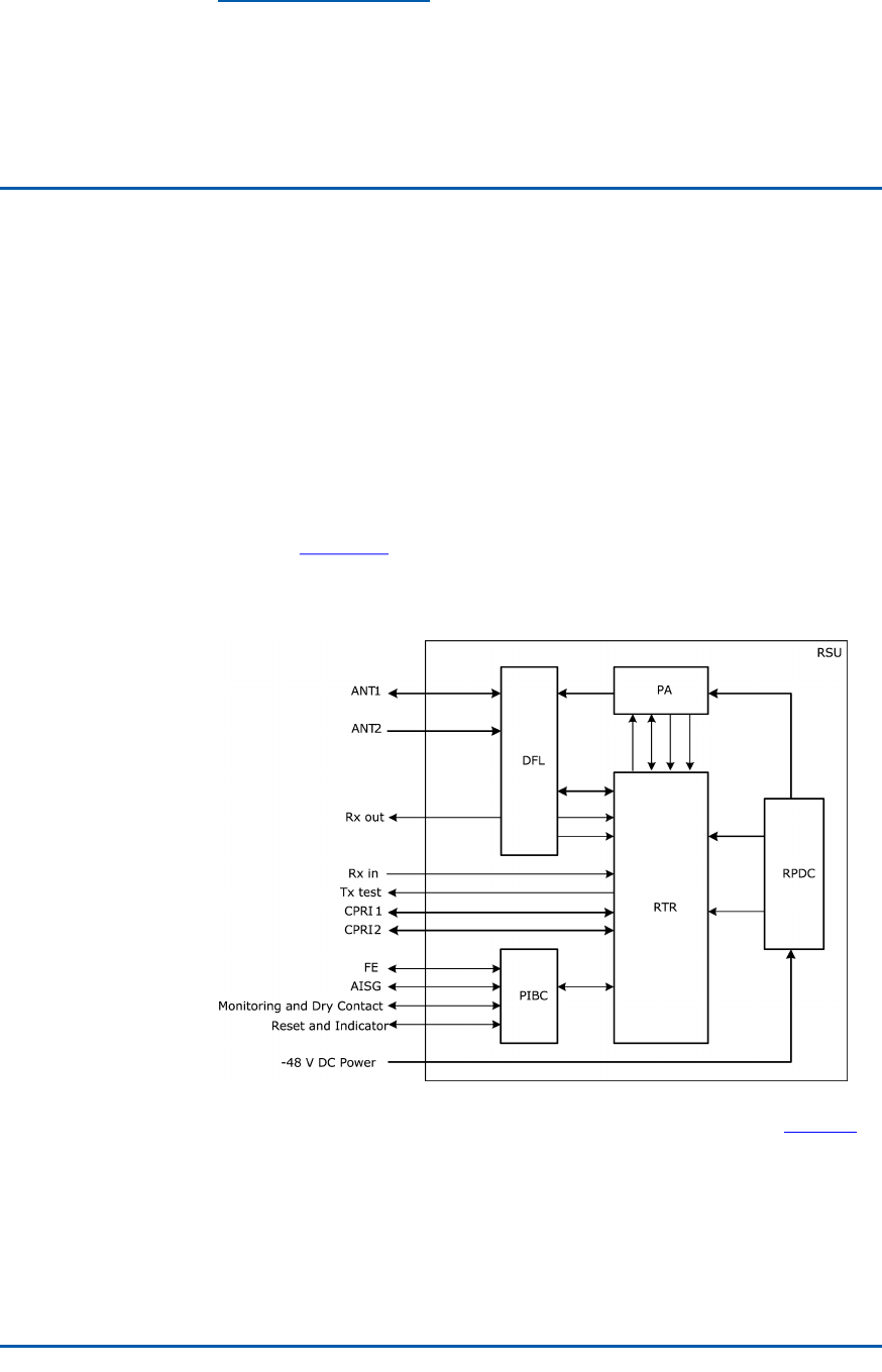
SystemArchitecture
AZXSDRRSUCconsistsofthetransmit/receivesignalboard
(RTR),poweramplier(PA),duplexer(DFL),andpowersupply
(RPDC).Figure3showstheschematicdiagramoftheZXSDR
RSUC.
FIGURE3SCHEMATICDIAGRAMOFTHEZXSDRRSUC
ThefunctionsofZXSDRRSUC’ssubsystemisshownasTable3.
CondentialandProprietaryInformationofZTECORPORATION13

ZXSDRRSUCUserManual
TABLE3THEFUNCTIONSOFSUBSYSTEM
PartDescription
RTR
RTR,theunitthatintegratestheprocessor ,clock,
CPRIinterface,DPDdigitalpredistortion,RF
transmittingandreceivingfunctions,isthecore
unitoftheZXSDRRSUC.
PA
�AmpliesdownlinkRFsignalinputviatheRTR
andthensendsthesignaltotheDFL
�Providesdigitalpre-distortionfeedbacksignals
fortheRTR
�ProvidesaPAoutputenable/disableinterface
DFL
�Performslteringandlownoiseamplicationof
thereverseCDMAsignalfromtheantenna
�FilterstheforwardRFsignaltobesent
�ReportsLNAalarmstotheRTR
�Inthecaseofmain/diversitycombinedcabinets,
themainreceiveLNAoutputendoftheDFL
hasthepowersplitterfunctionandreservesan
externalport(Rxout)
RPDC
Converts-48VDCinputpowersupplytoDCpower
supplyrequiredbythePA,RTR,orDFL
SignalProcessingFlow
TheinternalsignalprocessingowofZXSDRRSUCisasbelow:
�Forwardlinkprocessing
ThebusinessdatafromBBUenterstheRTR,andthenforinter-
mediatefrequencyprocessing.Afterthepoweramplication
senttotheantennafortransmission.
�Reverselinkprocessing
ThereverseCDMAsignalsfromtheantennaareconvertedto
basebanddigitalsignalbyRTR,thensendtoBBU.
TechnicalSpecifications
PhysicalIndices
Dimension
ThedimensionsofZXSDRRSUCinmmare:482.6(H)×88(W)
×360.0(D).
14CondentialandProprietaryInformationofZTECORPORATION

Chapter3TechnicalDescripition
Weight
WeightofaZXSDRRSUC:<10kg(22.05pounds).
PowerIndices
�PowerSupply
-48VDCVoltagerange:-37V~-62V .
�PowerConsumption
Inthecaseof1S-1T ,4C/S,15W/C,thetotalpowerconsump-
tionoftheequipmentis270W .
CapacityIndices
ZXSDRRSUCCapacityIndicesisshownasTable4
TABLE4ZXSDRRSUCCAPACITYINDICES
ItemCarrierssupported
18C1X
24C1X+4CDO
3theMAX8C/1S-1T
TemperatureandHumidity
Temperature:-40℃~+55℃.Thechangefrequencymustbeless
than0.5℃/min.
Relativehumidity:5%~95%
EnvironmentalClasses
�GradeOfProtection:IP55
�GroundingRequirements:Jointgroundingresistanceless1W;
BTSgroundingresistanceless5W.
�Noise:Noiseofworkingenvironment:less65dBA
CondentialandProprietaryInformationofZTECORPORATION15

ZXSDRRSUCUserManual
ReliabilityIndices
�MeanTimeBetweenFailures(MTBF):>100,000hours
�MTTR(MeanTimeToRepair):<0.5hour
�Availability:>99.999%
RFIndices
RFindicesoftheZXSDRRSUCcomplywith3GPP2C.S0010-C,
RecommendedMinimumPerformanceStandardsforcdma2000
SpreadSpectrumBaseStationand3GPP2C.S0032-A,Recom-
mendedMinimumPerformanceStandardsforCDMA2000High
RatePacketDataAccessNetwork.
Table5illustratesthe800MHztransmitterindices.
TABLE5800MHZTRANSMITTERINDICES
NameIndex
Operatingband800MHz(BandClass0)
Transmitteroutput
frequencytolerance
±0.01ppm
Occupiedchannel
bandwidth
1.23MHz(BandClass0)
OutputpowerattheT op
ofCabinet(TOC)
60W
Totaltransmitpower
Thetotaltransmitpoweriswithin+2dB
and-2dBofthemanufacturer’srated
power .
ModulationmodeQuadratureamplitudemodulation
Conductedspurious
emissionandradiated
spuriousemission
suppression
<-45dBc@±750kHzoffsetCenterFreq
(RBW30kHz)
<-60dBc@±1.98MHzoffsetCenter
Freq(RBW30kHz)
>4MHzOFFSET:
<-36dBm(RBW1kHz)@9KHz<f<
150KHz
<-36dBm(RBW10kHz)@150KHz<f<
30MHz
<-30dBm(RBW1MHz)@1GHz<f<
12.5GHz
4-6.4MHzOFFSET:
<-36dBm(RBW1kHz)@30MHz<f<1GHz
6.4MTO16MOFFSET:
<-36dBm(RBW10kHz)@30MHz<f<
1GHz
>16MHzOFFSET:
<-36dBm(RBW100kHz)@30MHz<f<
16CondentialandProprietaryInformationofZTECORPORATION

Chapter3TechnicalDescripition
NameIndex
1GHz
Transmitterintermodu-
lationperformance
IfoneBTStransmitsattheratedpower
butanotherBTS’outputpoweris30dB
lessthantheformer’sratedpower .When
thepowersoftwoBTSsarecombined
ontheantennaport,thegenerated
intermodulationspuriousemission
meetstheconductedspuriousemission
requirement.TheIFdifferenceofthe
transmitsignalsoftwoBTSsis1.25M.
PilottimetoleranceThePNtimetolerancefallswithin3usand
theinter-carriertolerancefallswithin1us.
Timedifference:<±50ns
TimeTolerance/phase
toleranceofpilotchannel
tootherchannelsPhasedifference:<0.05rad
WaveformqualityRhoisgreaterthan0.970dBmwith
congurationofasinglepilot.
Pilotcodedomainpower
Withthestandard9CHconguration,the
pilotcodedomainpowerisintherangeof
-7.0±0.5dB.
Inactivechannelcode
domainpower
Withthestandard9CHconguration,the
inactivechannelcodedomainpowerisless
than-27dB.
DOMACinactivechannel
codedomainpower
Withcongurationof13FLUSs,theMAC
inactivechannelcodedomainpowerisless
than-29.5dB(type2).
DODATAchannelcode
domainpower
Withcongurationof13FLUSsattherate
of614.44kbs(test1),theDATAchannel
codedomainpowerisintherangeof-15.5
dBto-14.5dB.
Pilotchannel:Rho>0.97
MACchannel:Rho>0.912
WavequalityofDO
channels
DATAchannel:Rho>0.97
RadiofrequencyFront
EndSWR
<2.0
Table6illustratesthe1.9GHztransmitterindices.
TABLE61.9GHZTRANSMITTERINDICES
NameIndex
Operatingband1.9GHz(BandClass1)
Transmitteroutput
frequencytolerance
±0.01ppm
CondentialandProprietaryInformationofZTECORPORATION17

ZXSDRRSUCUserManual
NameIndex
Occupiedchannel
bandwidth
1.25MHz
OutputpowerattheT op
ofCabinet(TOC)
60W
Totaltransmitpower
Thetotaltransmitpoweriswithin+2dB
and-2dBofthemanufacturer’srated
power .
ModulationmodeQuadratureamplitudemodulation
Conductedspurious
emissionandradiated
spuriousemission
suppression
<-45dBc@±885kHzoffsetCenterFreq
(RBW30kHz)
<-55dBc@±1.98MHzoffsetCenterFreq
(RBW30kHz)
>4MHzOFFSET :
<-36dBm(RBW1kHz)@9KHz<f<150
kHz
<-36dBm(RBW10kHz)@150kHz<f<
30MHz
<-36dBm(RBW100kHz)@30MHz<f<
1GHz
4-16MHzOFFSET :
<-30dBm(RBW30kHz)@1GHz<f<
12.5GHz
16M-19.2MOFFSET:
<-30dBm(RBW300kHz)@1GHz<f<
12.5GHz
>19.2MHzOFFSET:
<-30dBm(RBW1MHz)@1GHz<f<
12.5GHz
Transmitterintermodu-
lationperformance
IfoneBTStransmitsattheratedpower
butanotherBTS’outputpoweris30dB
lessthantheformer’sratedpower .When
thepowersoftwoBTSsarecombined
ontheantennaport,thegenerated
intermodulationspuriousemission
meetstheconductedspuriousemission
requirement.TheIFdifferenceofthe
transmitsignalsoftwoBTSsis1.25M.
PilottimetoleranceThePNtimetolerancefallswithin3usand
theinter-carriertolerancefallswithin1us.
Timedifference:<±50ns
TimeTolerance/phase
toleranceofpilotchannel
tootherchannelsPhasedifference:<0.05rad
WaveformqualityRhoisgreaterthan0.990dBmunderthe
congurationofasinglepilot.
Pilotcodedomainpower
Withthestandard9CHconguration,the
pilotcodedomainpowerisintherangeof
-7.0±0.5dB.
Inactivechannelcode
domainpower
Withthestandard9CHconguration,the
inactivechannelcodedomainpowerisless
than-27dB.
18CondentialandProprietaryInformationofZTECORPORATION

Chapter3TechnicalDescripition
NameIndex
DOMACinactivechannel
codedomainpower
Withcongurationof13FLUSs,theMAC
inactivechannelcodedomainpowerisless
than-29.5dB(type2).
DODATAchannelcode
domainpower
Withcongurationof13FLUSsattherate
of614.44kbs(test1),theDATAchannel
codedomainpowerisintherangeof-15.5
dBto-14.5dB.
Pilotchannel:Rho>0.97
MACchannel:Rho>0.912
WavequalityofDO
channels
DATAchannel:Rho>0.97
RadiofrequencyFront
EndSWR
<2.0
Table7illustratesthe800MHzreceiverindices.
TABLE7800MHZRECEIVERINDICES
NameIndex
Operatingband800MHz(BandClass0)
Receiversensitivity<-115dBm
Receiverdynamicrange
Whenthelowerlimitisthereceiver
sensitivityandtheupperlimit(noiselevel)
equals55dBm/1.23MHz(Eb/N0=10
dB±1dB),theFrameErrorRate(FER)is
lowerthan1%.
Noisegure<3
Singletonedesensitiza-
tion
Inthepresenceofasingletonethatis
50dBabovetheCDMAsignallevel,and
isatoffsetof±750kHzfromthecenter
frequency,theoutputpoweroftheMS
increasesbynomorethan3dB,andthe
FERislessthan1.5%.
Inthepresenceofasingletonethatis
75dBabovetheCDMAsignallevel,and
isatoffsetof±900kHzfromthecenter
frequency,theoutputpoweroftheMS
increasesbynomorethan3dB,andthe
FERislessthan1.5%.
Intermodulation
spuriousresponse
attenuation
BAND0:
Inthepresenceoftwointerferingtones
thatare60dBabovetheCDMAsignallevel,
andareatoffsetsof+900kHz,+1.7MHz,
-900kHzand-1.7MHzfromthecenter
frequency,theoutputpoweroftheMS
increasesbynomorethan3dB,andthe
FERislessthan1.5%.
Conductedspurious<-80dBm,measuredwithintheBTS
CondentialandProprietaryInformationofZTECORPORATION19

ZXSDRRSUCUserManual
NameIndex
emissionsandradiated
spuriousemissions
receiveband
<-60dBm,measuredwithintheBTS
transmitband
RadiofrequencyFront
EndSWR
<2.0
Table8illustratesthe1.9GHzreceiverindices.
TABLE81.9GHZRECEIVERINDICES
NameIndex
Operatingband1.9GHz(BandClass1&14)
Receiversensitivity<-115dBm
Receiverdynamicrange
Whenthelowerlimitisthereceiver
sensitivityandtheupperlimit(noiselevel)
equals-55dBm/1.23MHz(Eb/N0=
10dB±1dB),theFrameErrorRate(FER)is
lowerthan1%.
Noisegure<3
Adjacentchannel
selection(ACS)
BandClass6:>-53dBm(±2.5M)
Singletonedesensitiza-
tion
Inthepresenceofasingletonethatis
50dBabovetheCDMAsignallevel,and
isatoffsetof±750kHzfromthecenter
frequency,theoutputpoweroftheMS
increasesbynomorethan3dB,andthe
FERislessthan1.5%.
Inthepresenceofasingletonethatis
75dBabovetheCDMAsignallevel,and
isatoffsetof±900kHzfromthecenter
frequency,theoutputpoweroftheMS
increasesbynomorethan3dB,andthe
FERislessthan1.5%.
Intermodulation
spuriousresponse
attenuation
Inthepresenceoftwointerferingtones
thatare60dBabovetheCDMAsignallevel,
andareatoffsetsof1.25MHzand2.05
MHz,and-1.25MHzand-2.05MHzfrom
thecenterfrequency,theoutputpowerof
theMSincreasesbynomorethan3dB,
andtheFERislessthan1.5%.
Conductedspurious
emissionsandradiated
spuriousemissions
<-80dBm,measuredwithintheBTS
receiveband
<-60dBm,measuredwithintheBTS
transmitband
RadiofrequencyFront
EndSWR
<2.0
20CondentialandProprietaryInformationofZTECORPORATION

Chapter3TechnicalDescripition
InterfaceIndices
TheinterfaceindicesofZXSDRRSUCisshownasTable9.
TABLE9DESCRIPTIONOFZXSDRRSUC’SINTERFACES
TypeDescriptionIndex
CPRIFiber/Cable2CPRIinterfaces:1CPRIforBBU
orupper-levelRSU,1CPRIfor
lower-levelRSU
UEUminterface1Tx/Rx,1diversityreceivers
CondentialandProprietaryInformationofZTECORPORATION21

ZXSDRRSUCUserManual
Thispageisintentionallyblank.
22CondentialandProprietaryInformationofZTECORPORATION

Chapter4
HardwareDecsripition
TableofContents
Function...........................................................................23
Panel...............................................................................23
Button.............................................................................24
Indicators.........................................................................25
PanelInterfaces................................................................25
Function
RSUprovidesthefollowingfunctions:
�Communicationwiththebasebandsubrack
�ConversionbetweenairinterfaceRFsignalsanddigitalsignals
�RFsignalamplication,transmission,andreception
�Clocksynchronization.
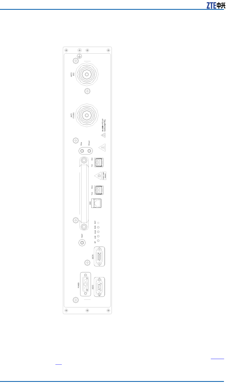
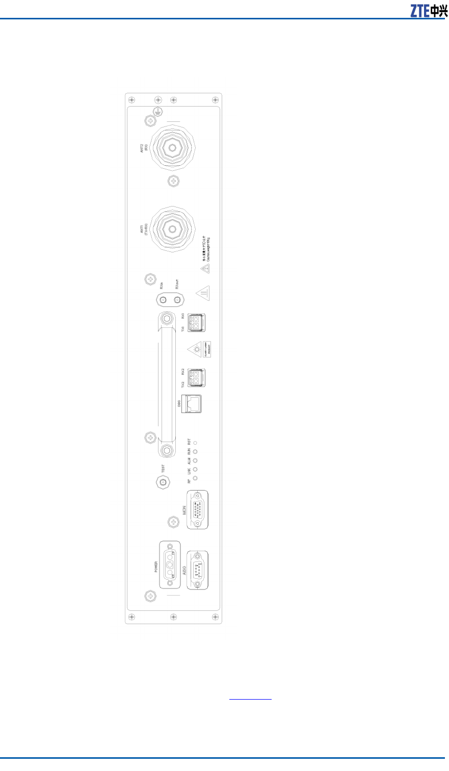
Panel
Figure4illustratestheZXSDRRSUCpanel.
CondentialandProprietaryInformationofZTECORPORATION23

Chapter4HardwareDecsripition
TABLE10ZXSDRRSUCPANELBUTTONDESCRIPTION
ButtonDescription
RSTResetbutton
Indicators
Table11describesZXSDRRSUCpanelindicators.
TABLE11ZXSDRRSUCPANELINDICATORDESCRIPTION
Indica-
tor
ColorMeaningDescription
RUNGreenRunning
status
indicator
Alwayson:TheRSUisresetting
orstartingup.
Blinkingat1Hz:TheRSUis
functioningproperly.
Blinkingat5Hz:TheRSUis
downloadingversionles.
Off:TheRSUfailstheself-check.
ALMRedAlarm
indicator
Off:Thereisonalarmorthe
RSUisresetting,startingup,or
downloadingversionles.
Blinkingat5Hz:Thereisacritical
alarm.
Blinkingat1Hz:Thereisaminor
alarm.
LNKGreenOptical
linkstatus
indicator
Alwayson:Theopticalconnection
isnormal.
Off:Theopticalberfails.
Blinkingat5Hz:Thislinkisused
astheclockreferencesourceand
thephaselockloop(PLL)isinthe
fastcapturestate.
Blinkingat0.25Hz:Thislinkis
usedastheclockreferencesource
andthephaselockloop(PLL)isin
thetracingstate.
RFOr-
ange
RFworking
status
indicator
Off:TheRFhasnooutput.
On:TheRFhasoutput.
PanelInterfaces
Table12describesZXSDRRSUCpanelinterfaces.
CondentialandProprietaryInformationofZTECORPORATION25

ZXSDRRSUCUserManual
TABLE12INTERFACESONTHEFRONTPANELOFTHEZXSDRRSUC
InterfaceEndAEndBDescription
ANT1(TX/RX)RSUTx/RxantennaConnectstotheTx/Rxantennaforthe
Tx/Rxmajorchannel.
ANT2(RX)RSURxantennaConnectstotheantennalfortheRx
minorantenna
RxoutRSURSUwithexpanded
frequencypoints
Frequency-pointexpansionoutput
interfaceforoutputtingtheRxsignalsof
themajorchannel.
RxinRSUwith
expanded
frequency
points
RSUFrequency-pointexpansioninput
interfaceforinputtingtheRxsignalsof
theminorchannel.
TX1/RX1RSUBBUorthe
upper-layer
cascadedRSU
ConnectstotheCPRIopticalinterfaceof
BBUortheupper-layercascadedRSU
TX2/RX2RSULower-layer
cascadedRSU
ConnectstotheCPRIopticalinterfaceof
thelower-layercascadedRSU
DBGRSUPCortesting
equipment(witha
thetestingboard)
CommissioningEthernetinterfaceand
testinginterface
TESTRSUTestingequipmentTxtestingsignalinterface
MONRSUExternal
equipment
Providesfourdry-contactinputinterfaces
andRS-485environmentmonitoring
interface
AISGRSUAntennaConnectstotheAISGinterface
POWERRSURFpowerofthe
powerdistribution
module
Powerinputinterface
26CondentialandProprietaryInformationofZTECORPORATION

Chapter5
HardwareInstallation
TableofContents
InstallingtheRSUModule...................................................27
ConnectingRSUMonitoringCable........................................35
InstallingOpticalFibersBetweenBBUandRSU......................36
InstallingtheInterconnectedCableBetweenBBUand
RSU.................................................................................38
InstallingtheRFJumper.....................................................40
InstallingtheRSUModule
Prerequisites�BeforeinstallingtheRFmodule,weartheESDwriststrapto
avoiddamagingtheRFmodule.
�TheRFcabinethasalreadybeeninstalled.
ContextFigure5showsthefrontpanelofaZXSDRRSUC.
CondentialandProprietaryInformationofZTECORPORATION27
Chapter5HardwareInstallation
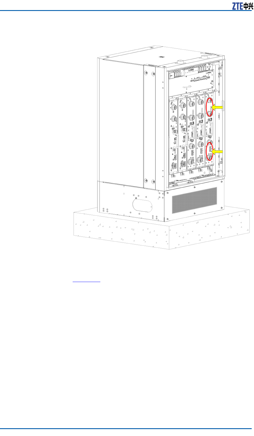
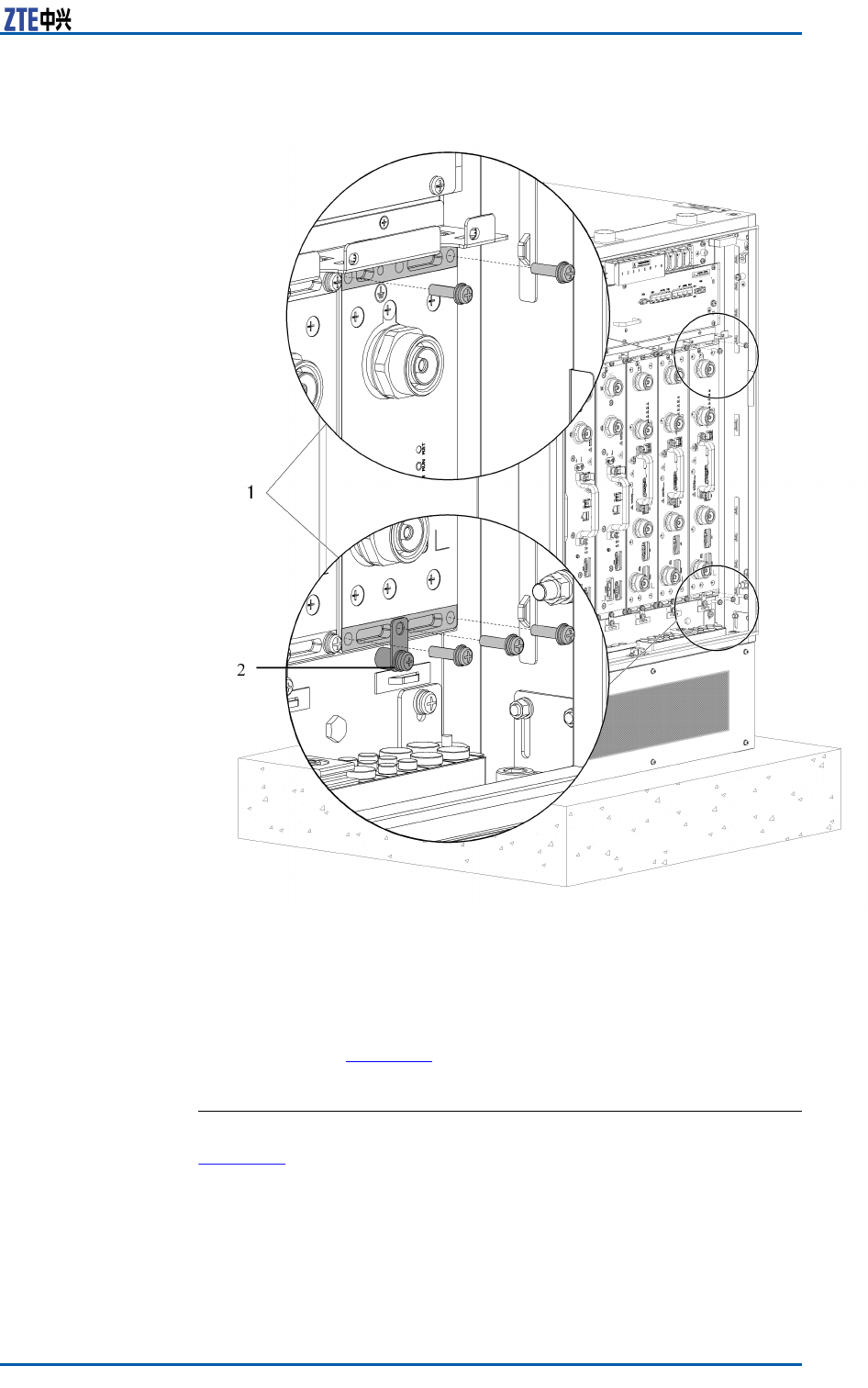
FIGURE10STEP5
1.Fixingthecabinetwith5
M5x20screws
2.Fixingthegroundinglug
6.Securethegroundlug.
AsshowninFigure10,theM5x20screwssecurestheground
lugoftheRSUmoduletothegroundpoints.
ENDOFSTEPS
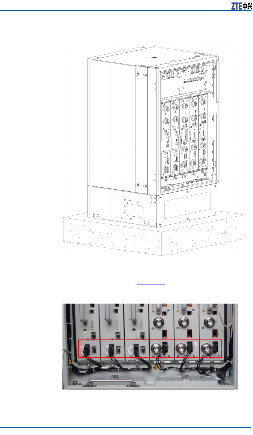
ResultFigure11showsthecompletionofinstallingtheRFmodule.
CondentialandProprietaryInformationofZTECORPORATION33
Chapter5HardwareInstallation
ConnectingRSUMonitoring
Cable
Prerequisites�ZXSDRRSUCRFcabinethasalreadybeeninstalled.
�TheRSUmodulehasalreadybeeninstalled.
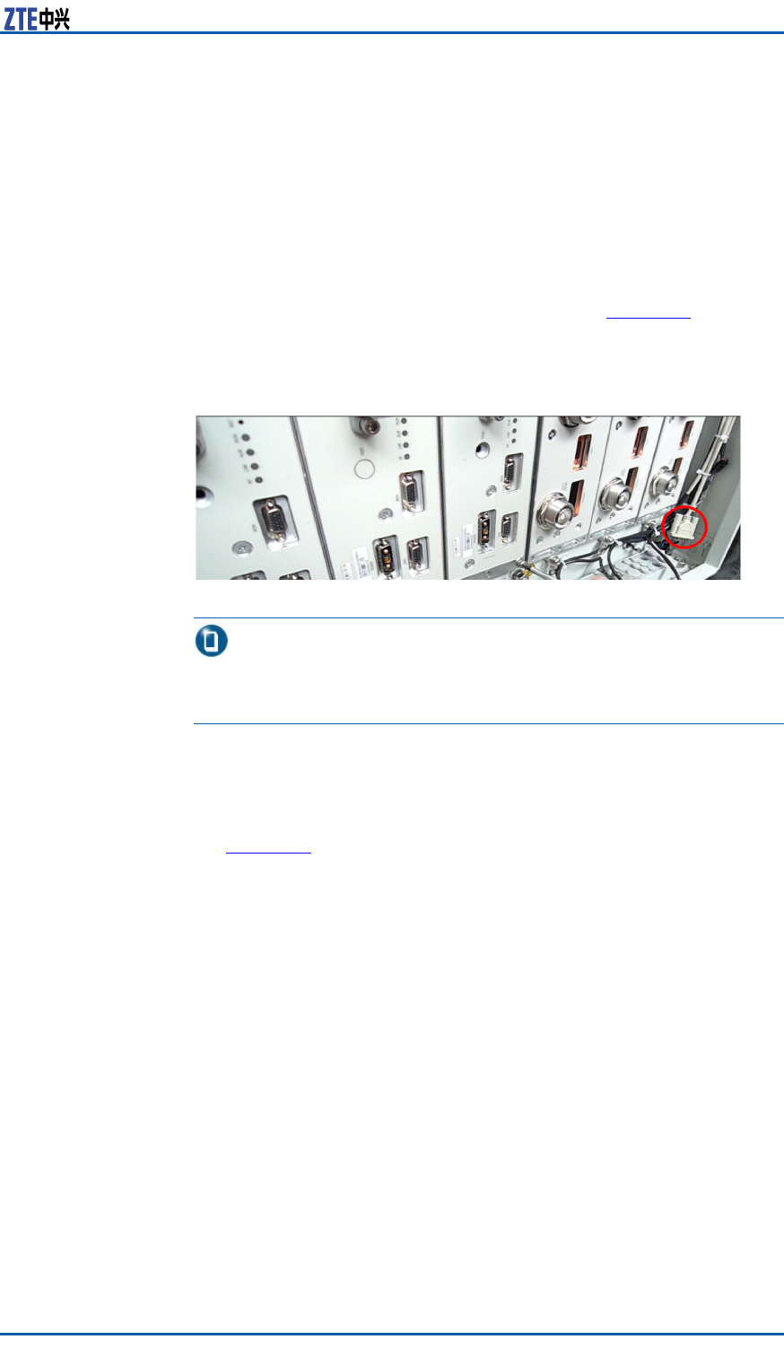
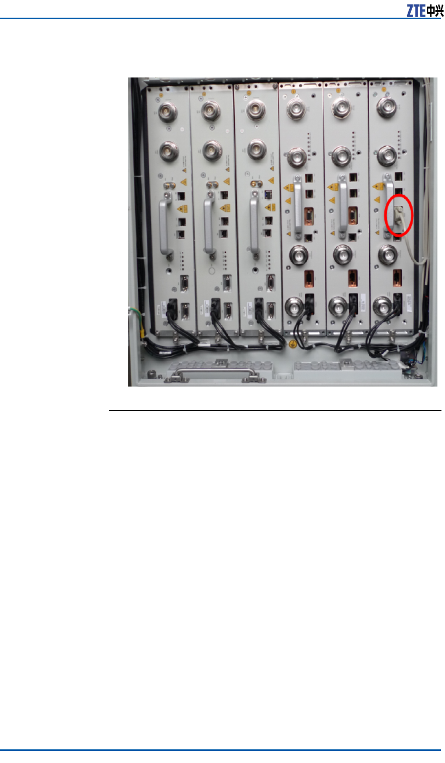
ContextTheRSUmonitoringcableoftheRFcabinetisroutedtotheright
sideoftheRFcabinetindelivery,asshowninFigure13.Afterthe
RSUmoduleisinstalled,inserttheterminaloftheRSUmonitoring
cabletotheMON(monitoring)interfaceoftheRSUmodule.
FIGURE13RSUMONITORINGCABLE
Note:
IfmultipleRSUmodulesneedtobemonitored,onlyoneRSUmod-
uleneedstobeconnectedtotheRSUmonitoringcable.
Steps1.ConnectoneendoftheRSUmonitoringcabletotheMON
(monitoring)interfaceoftheRSUmoduleandfastenthescrew.
2.BundletheRSUmonitoringcable.
Figure14showstheconnectedRSUmonitoringcable.
CondentialandProprietaryInformationofZTECORPORATION35
ZXSDRRSUCUserManual
FIGURE14INSTALLINGTHERSUMONITORINGCABLE
ENDOFSTEPS
InstallingOpticalFibers
BetweenBBUandRSU
Prerequisites�TheESDwriststrapmustbeworn.
�ThebasebandpowercabinetandtheRFcabinethavebeen
independentlyinstalled.
ContextWhenthebasebandpowercabinetandtheRFcabinetareinstalled
sidebysideortheyarefarawayfromeachother ,youneedto
connectBBUandRSUusingopticalbers.
Payattentiontothefollowingpointswheninstallingopticalbers:
�Donotdamagetheopticalbercladdingduringoperations.
�Protectopticalberconnectorsandavoidcontaminatingthem.
�Donotforciblybundleopticalbers.
�Curveopticalbersattheturning.
Steps1.Afxatemporarylabel.
36CondentialandProprietaryInformationofZTECORPORATION
Chapter5HardwareInstallation
Afxtemporarylabelstobothendsofthenewopticalberto
setupamapping.Ifmorethanoneopticalberneedstobe
installed,usedifferentlabelstodifferentiateopticalbers.
2.Routeopticalbers.
i.Opticalbersgooutfromthesidewaterproofmoduleofthe
basebandmoduleandgothroughtheroutingapertureson
thebase.
ii.Then,opticalbersgothroughtheroutingaperturesonthe
baseoftheRFcabinet,traversethewaterproofmodules,
andconnecttothesixopticalinterfacesforRFmodules.
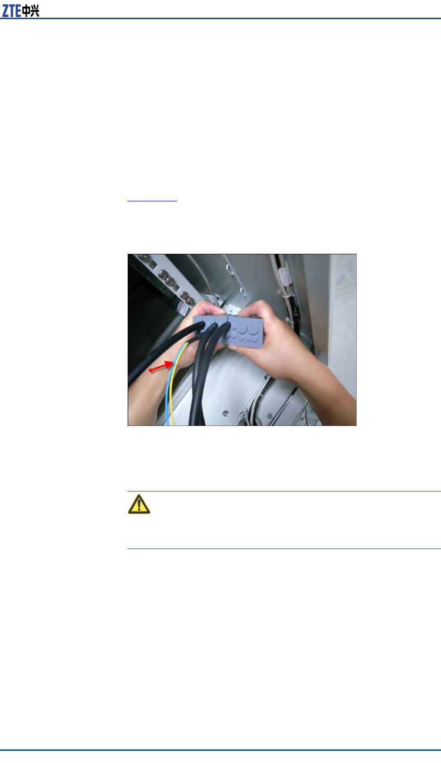
Figure15showshowopticalberstraversethewaterproof
modules.
FIGURE15WATERPROOFMODULETHROUGHWHICHOPTICALFIBERS
PASS
3.Insertopticalberconnectors.
Insertopticalberconnectorsaccordingtothemappingon
temporarylabels.
Caution:
Insertopticalberconnectorstightly.
4.Bundleopticalbers.
Bundleandsecureopticalbersalongtheroutingtroughs,
whichcomplieswithrelevantregulations.
5.Afxanengineeringlabeltoanopticalber .
Removethetemporarylabelfortheopticalberandafxan
engineeringlabel.
CondentialandProprietaryInformationofZTECORPORATION37
ZXSDRRSUCUserManual
Caution:
Protectanopticalberwiththewindingtubewhenroutingthe
opticalberinsidethecabinet.Protectanopticalberwith
thecorrugatedpipewhenroutingtheopticalberoutsidethe
cabinet.
ENDOFSTEPS
InstallingtheInterconnected
CableBetweenBBUand
RSU
Prerequisites�TheZXSDRRSUCcabinethasalreadybeeninstalled.
�TheBBUmoduleandRSUmodulehavealreadybeeninstalled.
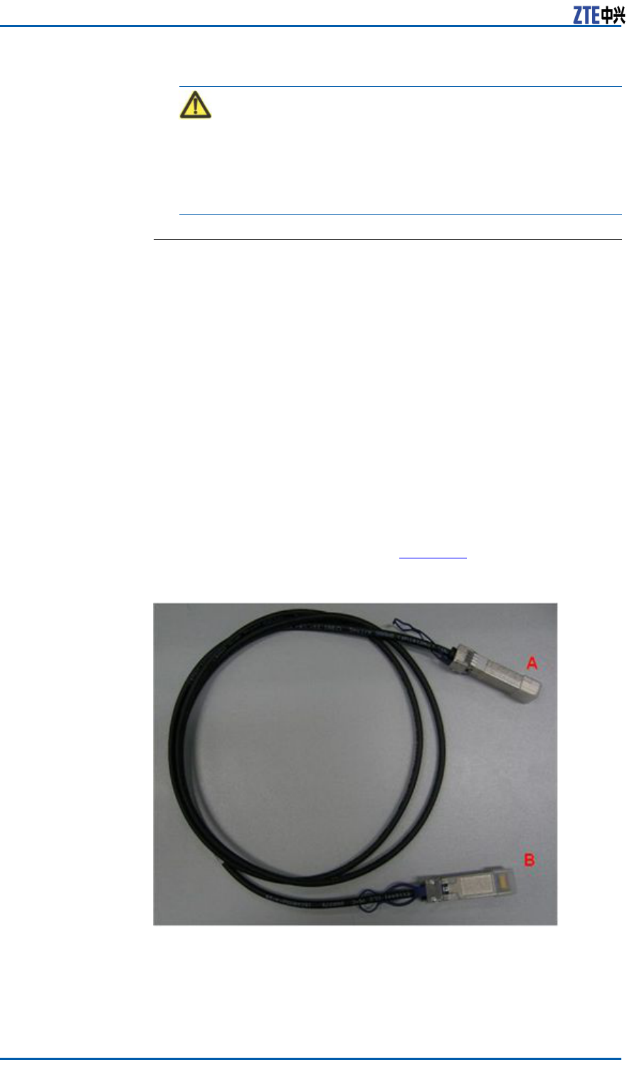
ContextZXSDRRSUCInthesystem,opticalbersorSFPcablescanbe
usedtoconnectBBUandRSU.Duringthestackedinstallationof
theZXSDRRSUC,a2mSFPhigh-speedcableisrecommended
forinterconnectingBBUandRSU.Figure16showsanSFPcable.
FIGURE16HIGH-SPEEDCABLE
Steps1.AfxtemporarylabelstobothendsoftheSFRcable,with
markings0-5tosetupone-to-onemappingwithinterfaces
TX0RX0toTX5RX5ofBBUandsixTX/RXinterfacesofRSU.
2.InsertoneendoftheSFPcabletoaTX/RXinterfaceofRSU.
38CondentialandProprietaryInformationofZTECORPORATION
Chapter5HardwareInstallation
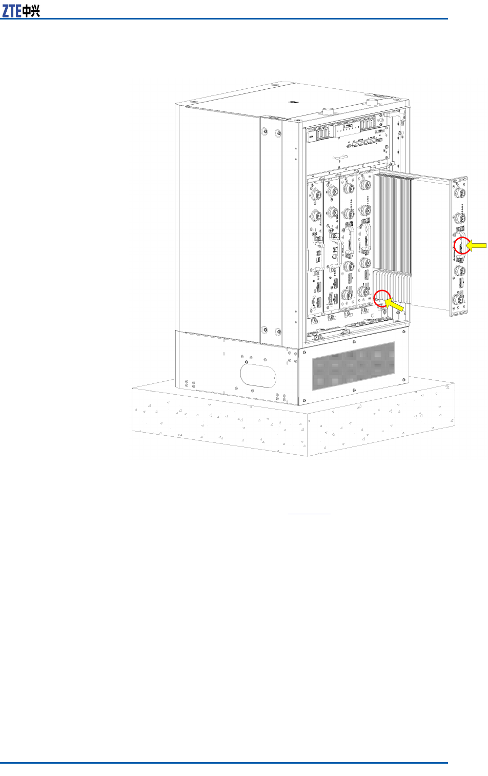
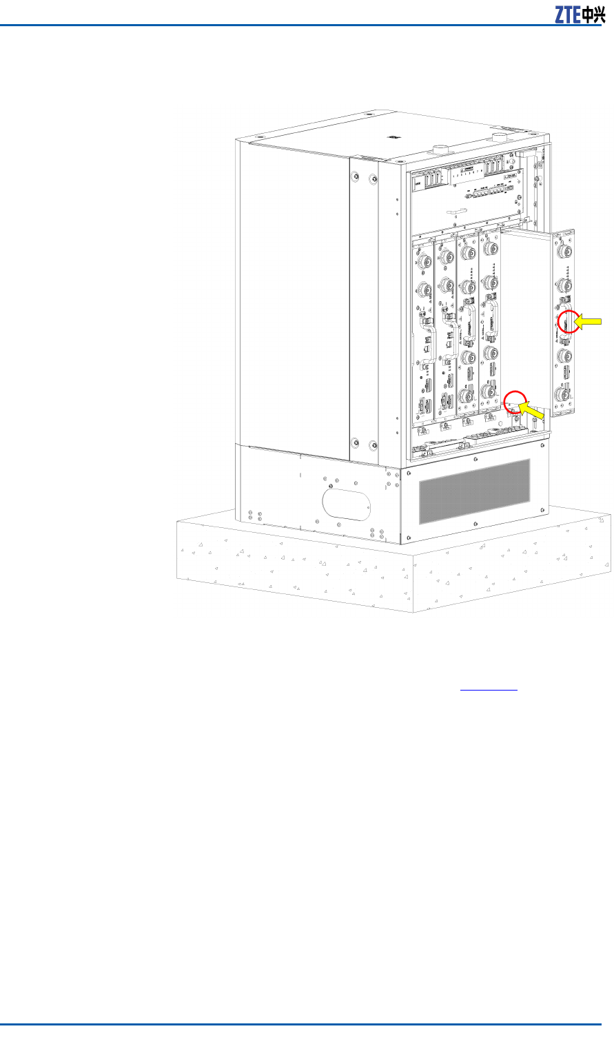
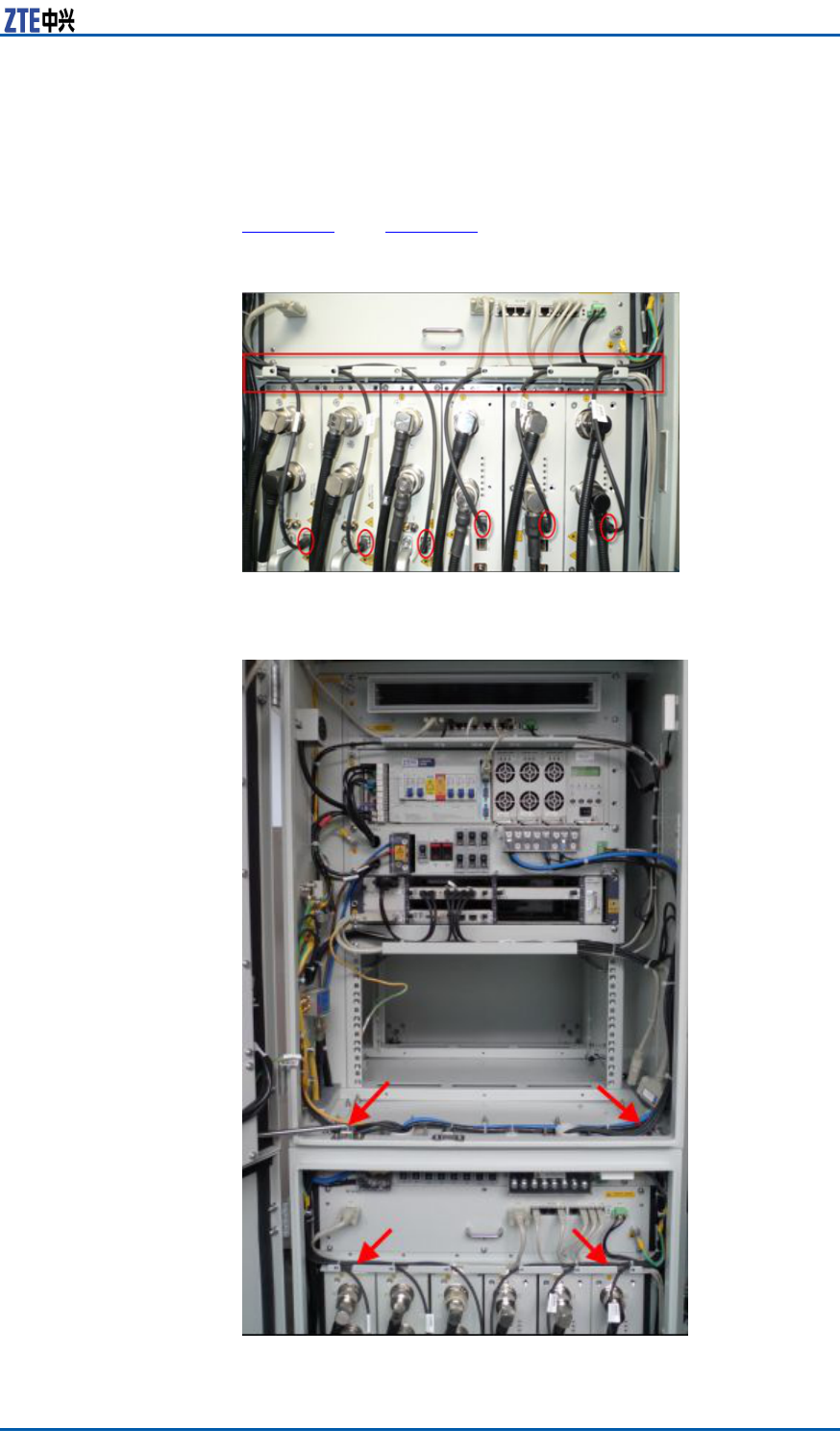
3.RoutetheSFPcablealongtheroutingtroughandcabinetsides
totheFSmoduleofBBU.TheSFPcablesconnectingtothe
RSUsinslots1to3ontheRFcabinetgothroughtheleftrouting
aperturesandthoseSFPcablesgothroughtherightapertures
ifconnectingtoslots4to6ontheRFcabinet,asshownin
Figure17andFigure18.
FIGURE17LAYOUTOFTHESFPCABLESINTHERFCABINET
FIGURE18SFPCABLELAYOUT
CondentialandProprietaryInformationofZTECORPORATION39
ZXSDRRSUCUserManual
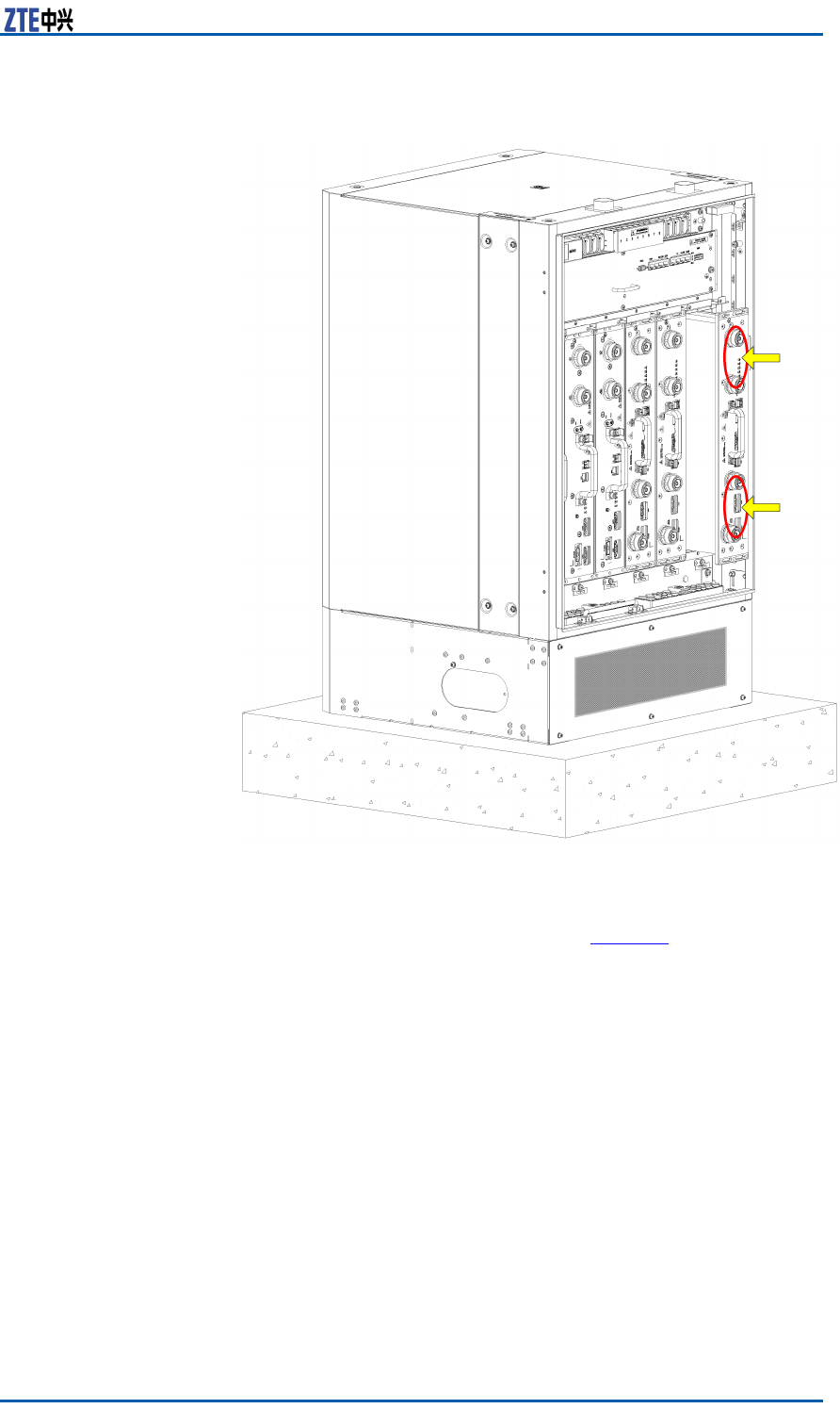
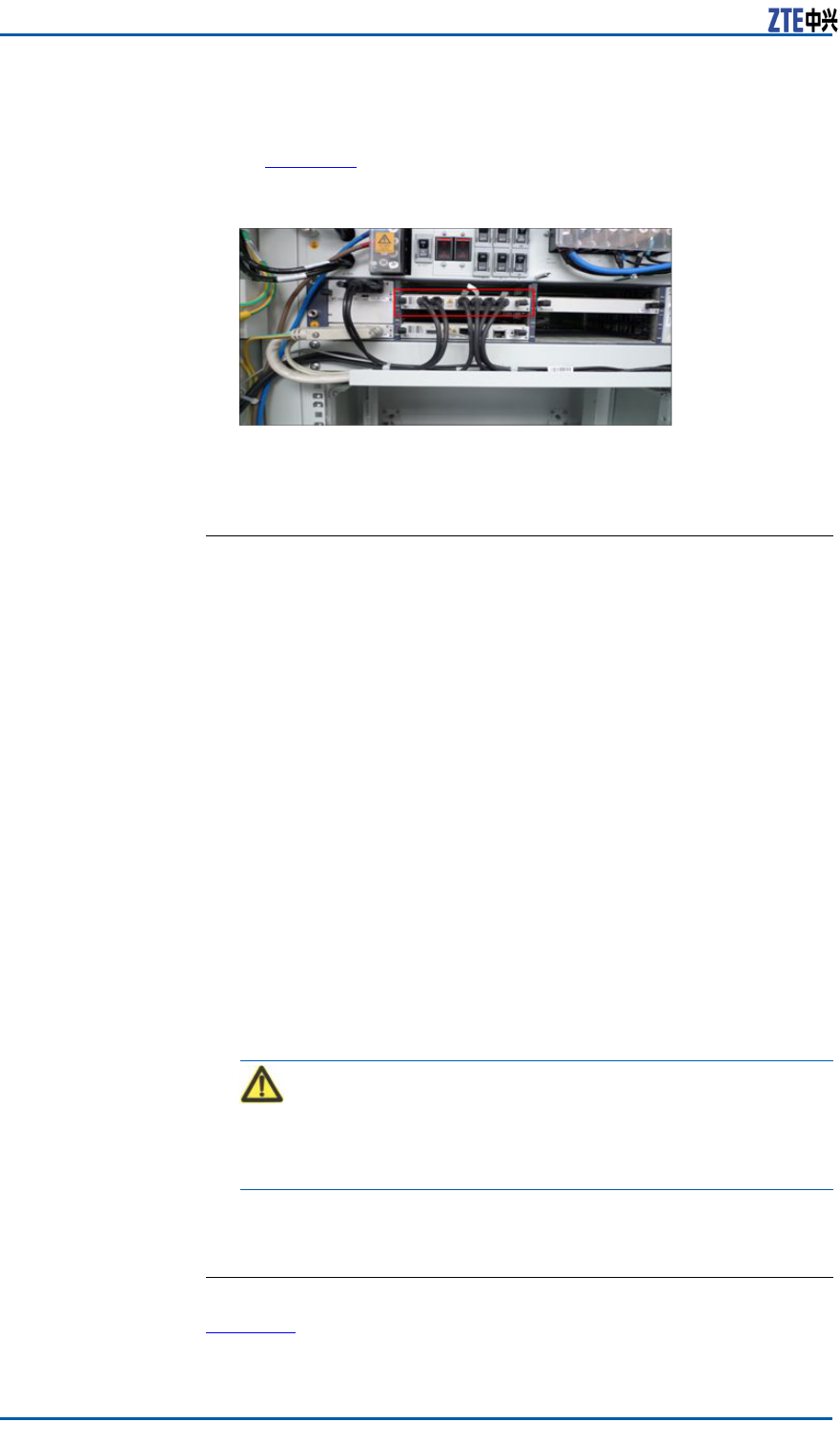
4.InsertSFPcablesintotheinterfacesTX0RX0toTX5RX5of
theBBUFSboardaccordingtothemarkings0-5,asshown
inFigure19.
FIGURE19FSBOARDCONNECTINGTOTHEBBU
5.BundleSFPcables.
6.Removetemporarylabelsandafxengineeringlabels.
ENDOFSTEPS
InstallingtheRFJumper
PrerequisitesTheZXSDRRSUCRFcabinetandothermoduleshavealreadybeen
installed.
ContextTheRFjumpersforthethreeZXSDRRSUCgothroughthewater-
proofmoduleontheright.
RemovethefrontbafeofthebasebeforeinstallingtheRF
jumpersandreseatthefrontbafeafteralljumpersarecom-
pletelyinstalled.
Steps1.ConnecttheRFjumperstoANT1andANT2interfacesofRSU
fromlefttoright.
2.WearthewaterproofrubberplugaftereverytwoRFjumpers
areinstalled.
3.Insertthehorizontalandlongitudinalslideblocksandusethe
hexagonringwrenchtofastenthem.
Caution:
Clampthewaterproofrubberplugtightlyandmakesurethat
theunusedcablingaperturewearstheplug.
4.RepeattheprecedingstepstoinstallotherRSU-related
jumpers.
ENDOFSTEPS
ResultFigure20showsthecompletionofinstallingtheRFjumpers.
40CondentialandProprietaryInformationofZTECORPORATION
Chapter5HardwareInstallation
FIGURE20ANTENNAFEEDERJUMPERINSTALLEDCOMPLETELY
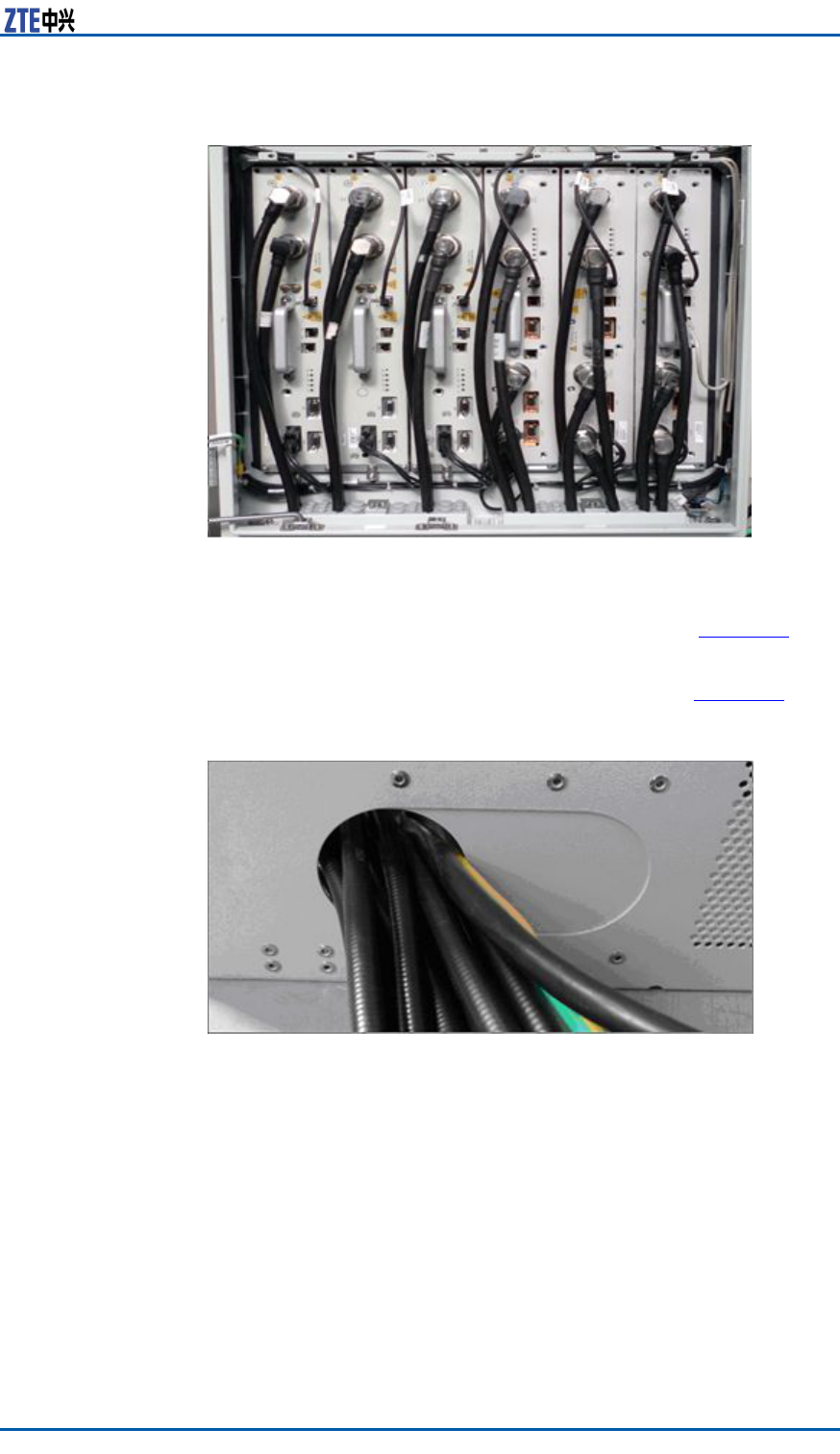
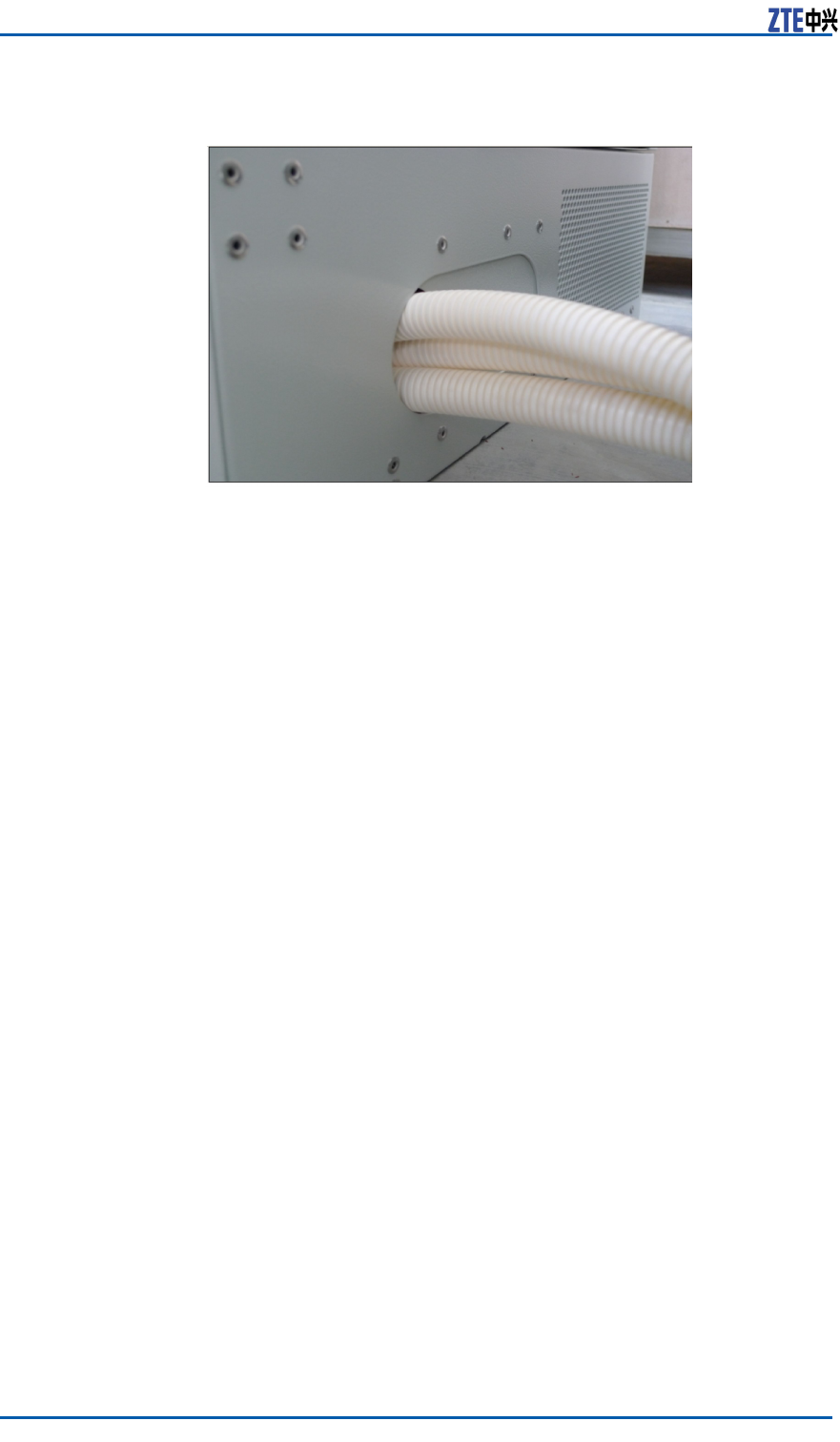
TheRFjumpersgooutfromthebase,asshowninFigure21.The
cablesbetweencabinetsmustbeprotectedwithprotectivetubes,
withoutanyexposedpartofthecablesandtheopeningsattwo
endsofthesecablesmustbesealed,asshowninFigure22.
FIGURE21LEAD-OUTOFTHEANTENNAFEEDERJUMPER
CondentialandProprietaryInformationofZTECORPORATION41
ZXSDRRSUCUserManual
FIGURE22CABLESINTUBES
42CondentialandProprietaryInformationofZTECORPORATION

Figures
Figure1ZXSDRRSUCPositioninaNetwork..........................10
Figure2OuterViewofZXSDRRSUC....................................11
Figure3SchematicDiagramoftheZXSDRRSUC...................13
Figure4ZXSDRRSUCPanel................................................24
Figure5ZXSDRRSUCPanel................................................28
Figure6Step1.................................................................29
Figure7Step2.................................................................30
Figure8Step3.................................................................31
Figure9Step4.................................................................32
Figure10Step5...............................................................33
Figure11RSUModuleInstalledCompletely...........................34
Figure12PowerCableConnectingtheRSU...........................34
Figure13RSUMonitoringCable..........................................35
Figure14InstallingtheRSUMonitoringCable.......................36
Figure15WaterproofModulethroughWhichOpticalFibers
Pass.................................................................37
Figure16High-SpeedCable................................................38
Figure17LayoutoftheSFPCablesintheRFCabinet.............39
Figure18SFPCableLayout.................................................39
Figure19FSBoardConnectingtotheBBU............................40
Figure20AntennaFeederJumperInstalledCompletely..........41
Figure21Lead-OutoftheAntennaFeederJumper.................41
Figure22CablesinTubes...................................................42
CondentialandProprietaryInformationofZTECORPORATION43

ZXSDRRSUCUserManual
Thispageisintentionallyblank.
44CondentialandProprietaryInformationofZTECORPORATION

Tables
Table1SafetySymbolsDescription......................................2
Table2ThePrimaryFunctionsofZXSDRRSUC......................12
Table3Thefunctionsofsubsystem......................................14
Table4ZXSDRRSUCCapacityIndices..................................15
Table5800MHzTransmitterIndices....................................16
Table61.9GHzTransmitterIndices.....................................17
Table7800MHzReceiverIndices........................................19
Table81.9GHzReceiverIndices.........................................20
Table9DescriptionofZXSDRRSUC’sinterfaces.....................21
Table10ZXSDRRSUCPanelButtonDescription.....................25
Table11ZXSDRRSUCPanelIndicatorDescription.................25
Table12InterfacesontheFrontPaneloftheZXSDRRSUC.....26
CondentialandProprietaryInformationofZTECORPORATION45

ZXSDRRSUCUserManual
Thispageisintentionallyblank.
46CondentialandProprietaryInformationofZTECORPORATION

Glossary
BBU
-BaseBandUnit
BS
-BaseStation
BSC
-BaseStationController
BTS
-BaseTransceiverStation
CDMA
-CodeDivisionMultipleAccess
CPRI
-CommonPublicRadioInterface
MS
-MobileStation
RF
-RadioFrequency
RSSI
-ReceivedSignalStrengthIndicator
RSU
-RFSystemUnit
SDR
-SoftwareDenedRadio
CondentialandProprietaryInformationofZTECORPORATION47