ZTE RSUC849 ZXSDR RSUC is CDMA Radio System Unit User Manual
ZTE Corporation ZXSDR RSUC is CDMA Radio System Unit
ZTE >
User manual

ZXSDRRSUC
RadioSystemUnitofCDMAwith1T2R
UserManual
HardwareVersion:HV1.00
ZTECORPORATION
NO.55,Hi-techRoadSouth,ShenZhen,P .R.China
Postcode:518057
Tel:+86-755-26771900
Fax:+86-755-26770801
URL:http://ensupport.zte.com.cn
E-mail:support@zte.com.cn

LEGALINFORMATION
Copyright©2011ZTECORPORATION.
Thecontentsofthisdocumentareprotectedbycopyrightlawsandinternationaltreaties.Anyreproductionor
distributionofthisdocumentoranyportionofthisdocument,inanyformbyanymeans,withoutthepriorwritten
consentofZTECORPORATIONisprohibited.Additionally,thecontentsofthisdocumentareprotectedby
contractualcondentialityobligations.
Allcompany,brandandproductnamesaretradeorservicemarks,orregisteredtradeorservicemarks,ofZTE
CORPORATIONoroftheirrespectiveowners.
Thisdocumentisprovided“asis”,andallexpress,implied,orstatutorywarranties,representationsorconditions
aredisclaimed,includingwithoutlimitationanyimpliedwarrantyofmerchantability,tnessforaparticularpurpose,
titleornon-infringement.ZTECORPORATIONanditslicensorsshallnotbeliablefordamagesresultingfromthe
useoforrelianceontheinformationcontainedherein.
ZTECORPORATIONoritslicensorsmayhavecurrentorpendingintellectualpropertyrightsorapplications
coveringthesubjectmatterofthisdocument.ExceptasexpresslyprovidedinanywrittenlicensebetweenZTE
CORPORATIONanditslicensee,theuserofthisdocumentshallnotacquireanylicensetothesubjectmatter
herein.
ZTECORPORATIONreservestherighttoupgradeormaketechnicalchangetothisproductwithoutfurthernotice.
UsersmayvisitZTEtechnicalsupportwebsitehttp://ensupport.zte.com.cntoinquirerelatedinformation.
TheultimaterighttointerpretthisproductresidesinZTECORPORATION.
RevisionHistory
RevisionNo.RevisionDateRevisionReason
R1.12012–03–15Addedacautionforuser’schangesormodicationactioninFCC
&ICSTATEMENT.
R1.02010–05–25FirstEdition
SerialNumber:SJ-20101019140047-002
PublishingDate:2012-03-15(R1.1)
FCC&ICSTATEMENT
ThisdevicecomplieswithPart15oftheFCCRules.Operationissubjecttothefollowing
twoconditions:
1.Thisdevicemaynotcauseharmfulinterference.
2.Andthisdevicemustacceptanyinterferencereceived,includinginterferencethatmay
causeundesiredoperation.
Note:
ThisequipmenthasbeentestedandfoundtocomplywiththelimitsforaClassAdigital
device,pursuanttoPart15oftheFCCRules.Theselimitsaredesignedtoprovide
reasonableprotectionagainstharmfulinterferencewhentheequipmentisoperatedin
acommercialenvironment.Thisequipmentgenerates,uses,andcanradiateradio
frequencyenergyand,ifnotinstalledandusedinaccordancewiththeinstructionmanual,
maycauseharmfulinterferencetoradiocommunications.
Operationofthisequipmentinaresidentialareaislikelytocauseharmfulinterferencein
whichcasetheuserwillberequiredtocorrecttheinterferenceathisownexpense.
Caution!
Changesormodicationstothisunitnotexpresslyapprovedbythepartyresponsiblefor
compliancewillvoidtheuser’sauthoritytooperatetheequipment.Anychangetothe
equipmentwillvoidFCCandICgrant.
I

II

FCCRadiationExposure
Statement
ThisequipmentcomplieswithFCCradiationexposurelimitssetforthforanuncontrolled
environment.Thisequipmentshouldbeinstalledandoperatedwithminimumdistance4m
betweentheradiator&yourbody.
I

II

DeclarationofRoHS
Compliance
Tominimizetheenvironmentalimpactandtakemoreresponsibilitytotheearthwelive,
thisdocumentshallserveasformaldeclarationthatZXSDRRSUCmanufacturedby
ZTECORPORATIONareincompliancewiththeDirective2002/95/ECoftheEuropean
Parliament-RoHS(RestrictionofHazardousSubstances)withrespecttothefollowing
substances:
lLead(Pb)
lMercury(Hg)
lCadmium(Cd)
lHexavalentChromium(Cr(VI))
lPolyBrominatedBiphenyls(PBB’s)
lPolyBrominatedDiphenylEthers(PBDE’s)
…
TheZXSDRRSUCmanufacturedbyZTECORPORATIONmeettherequirementsofEU2002/95/EC;
however,someassembliesarecustomizedtoclientspecications.Additionofspecialized,
customer-speciedmaterialsorprocesseswhichdonotmeettherequirementsofEU2002/95/EC
maynegateRoHScomplianceoftheassembly.T oguaranteecomplianceoftheassembly,the
needforcompliantproductmustbecommunicatedtoZTECORPORATIONinwrittenform.This
declarationisissuedbasedonourcurrentlevelofknowledge.Sinceconditionsofuseareoutside
ourcontrol,ZTECORPORATIONmakesnowarranties,expressorimplied,andassumesnoliability
inconnectionwiththeuseofthisinformation.
I

II
Chapter1
SafteyDescription
TableofContents
SafetySpecicationsGuide........................................................................................1-1
SafetySymbols..........................................................................................................1-2
SafetyInstructions......................................................................................................1-3
1.1SafetySpecicationsGuide
Thesesafetyinstructionsmustbeconsideredassupplementaryforlocalsafety
regulations.Theprioritymustbegiventolocalsafetyregulationsifthereisanyconict
betweenthetwo.
Themaintenancepersonnelmusthavetheknowledgeofsafetyoperationsand
maintenancewithrequiredqualicationandtechnicalbackground.
Warning!
Thisdevicecomplieswithpart15oftheFCCRules.Operationissubjecttothefollowing
twoconditions:
lThisdevicemaynotcauseharmfulinterference.
lThisdevicemustacceptanyinterferencereceived,includinginterferencethatmay
causeundesiredoperation.
Changesormodicationsnotexpresslyapprovedbythepartyresponsibleforcompliance
couldvoidtheuser'sauthoritytooperatetheequipment.
TheequipmentisintendedforinstallationinRESTRICTEDACCESSLOCATIONS.
Alltheoperationandmaintenancepersonnelmustfollowthesafetyprecautionsand
instructionsprovidedbyZTECorporationtoavoidanyaccident.
Note:
ZTECorporationdoesnotbearanyliabilitiesincurredbecauseofviolationofthe
universalsafetyoperationrequirements,orviolationofsafetystandardsfordesigning,
manufacturingandusingtheequipment.
1-1
SJ-20101019140047-002|2012-03-15(R1.1)ZTEProprietaryandCondential
ZXSDRRSUCUserManual
FCCRadiationExposureStatement:
ThisequipmentcomplieswithFCCradiationexposurelimitssetforthforanuncontrolled
environment.Thisequipmentshouldbeinstalledandoperatedwithminimumdistance3m
betweentheradiator&yourbody.
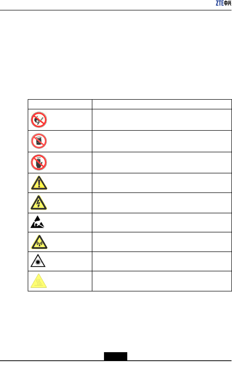
1.2SafetySymbols
Table1-1listssafetysymbols.Theyaretoprompttheuserofthesafetyprecautionstobe
observedduringZXSDRRSUCoperationandmaintenance.
Table1-1SafetySymbolsDescription
SafetySymbolsMeaning
Nosmoking:Smokingisforbidden
Noammables:Noammablescanbestored.
Notouching:Donottouch.
Universalalertingsymbol:Generalsafetyattentions.
Electricshock:Riskofelectricshock.
Electrostatic:Thedevicemaybesensitivetostaticelectricity.
Microwave:Bewareofstrongelectromagneticeld.
Laser:Bewareofstronglaserbeam.
Scald:Bewareofscald.
Amongstthesesafetysymbols,theuniversalalarmsymbolsareclassiedintothreelevels:
danger,warning,andcaution.Theformatsandmeaningsofthethreelevelsaredescribed
asbelow:
1-2
SJ-20101019140047-002|2012-03-15(R1.1)ZTEProprietaryandCondential
Chapter1SafteyDescription
Danger!
Indicatesapotentiallyhazardoussituationwhich,ifnotavoided,willresultindeathor
seriousinjuryofpeople,orequipmentdamagesandbreakdown.
Warning!
Indicatesapotentiallyhazardoussituationwhich,ifnotavoided,couldresultindeathor
seriousinjury.
Caution!
Indicatesapotentiallyhazardoussituationwhich,ifnotavoided,couldresultinserious
injuries,equipmentdamagesorinterruptionofpartservices.
1.3SafetyInstructions
Thissectiondescribesthesafetyinstructionsrelatedtoelectricalsafety,antistatic,heavy
objectsandmodules.
ElectricalSafetyInstructions
Thefollowingaretheelectricalsafetyinstructionsabouttools,highvoltage,powercables,
holesandlightning:
lTools
Usespecialtoolsratherthancommontoolsforhigh-voltageandACoperations.
lHighVoltage
Danger!
Highvoltageishazardous.Directorindirectcontactwithhighvoltageormainsupply
usingawetobjectcouldresultindeath.
àStrictlyfollowlocalsafetyrulestoinstallACpowerdevices.
àInstallationstaffmustbequaliedforperforminghigh-voltageandACoperations.
1-3
SJ-20101019140047-002|2012-03-15(R1.1)ZTEProprietaryandCondential
ZXSDRRSUCUserManual
àDonotwearanywatch,handchain,bracelet,ringoranyotherconductiveobjects
duringsuchoperations.
àPreventmoisturefromaccumulatingontheequipmentduringoperationsina
dampenvironment.
lPowerCable
Warning!
Neverinstalloruninstallpowercableswhiletheyarelive.Otherwise,thepowercable,
whencontactingaconductor,mayresultinsparksorelectricarccausingareoreven
damagetoeyes.
àMakesureofshuttingoffpowersupplybeforeinstallingordisconnectingapower
cable.
àBeforeconnectingthepowercable,makesurethattheconnectingcableandits
labelareappropriatefortheactualinstallationrequirements.
lDrillingHoles
Warning!
Itisnotallowedtodrillchassisholeswithoutpermission.
àUnqualieddrillingcoulddamagewiringandcablesinsidethechassis.
Additionally,metalpiecesinsidethechassiscreatedbythedrillingcouldresult
inashortcircuit.Useinsulationprotectionglovesandrstmovecablesinsidea
chassisawaywhendrillingisnecessaryonachassis.
àProtecteyesduringdrillingasdustoryingdebrismaydamageeyes.
àCleananydebrisintimeafterdrilling.
lLightning
Danger!
Donotperformhigh-voltage,AC,irontowerormastoperationsinathunderstorm.
Thunderstormswouldgiverisetoastrongelectromagneticeldintheatmosphere.
Therefore,theequipmentmustbegroundedandprotectedintimeagainstlightning
strikes.
1-4
SJ-20101019140047-002|2012-03-15(R1.1)ZTEProprietaryandCondential
Chapter1SafteyDescription
AntistaticSafetyInstructions
Caution!
Staticelectricityproducedbyhumanbodycandamagestatic-sensitivecomponentson
circuitboard,suchaslarge-scaleintegratedcircuits.
lFrictioncausedbyhumanbodyactivitiesistherootcauseofelectrostaticcharge
accumulation.Staticvoltagecarriedbyahumanbodyinadryenvironmentcanbe
upto30kV,andcanremainthereforalongtime.Anoperatorwithstaticelectricity
maydischargeelectricitythroughacomponentwhenhe/shetouchestheconductor
andcausingdamage.
lWearanantistaticwriststrap(theotherendofwriststrapmustbewellgrounded)
beforetouchingtheequipmentorholdingaplug-inboard,circuitboard,Integrated
Circuit(IC)chiporotherdevices,topreventhumanstaticelectricityfromdamaging
sensitivecomponents.
lTheantistaticwriststrapusedmustbesubjecttoregularcheck.Donotreplacethe
cableofanantistaticwriststrapwithanyothercables.
lDonotcontactstatic-sensitivemoduleswithanyobjectthateasilygeneratesstatic
electricity.Forexample,frictionofpackagebag,transferboxandtransferbeltmade
frominsulationplasticmaycausestaticelectricityoncomponents.Dischargeofstatic
electricitymaydamagecomponentswhentheycontactahumanbodyortheground.
lModulesshouldonlycontactmaterialssuchasanantistaticbag.Keepmodulesin
antistaticbagsduringstorageandtransportation.
lDischargestaticelectricityofthetestdevicebeforeuse,thatis,groundthetestdevice
rst.
lDonotplacethemodulenearastrongDCmagneticeld,suchasthecathode-ray
tubeofamonitor.Keepthemoduleatleast10cmaway.
HoistingHeavyObjects
Warning!
Whenhoistingheavyobjects,ensurethatnobodyisstandingorwalkingunderthehoisted
object.
lEnsurethehoistercanmeethoistingrequirementswhendisassemblingheavy
equipment,ormovingandreplacingequipment.
lTheinstallationpersonnelmustbedulytrainedandqualiedforhoistingoperations.
lHoistingtoolsmustbeinspectedandcompletebeforeservice.
1-5
SJ-20101019140047-002|2012-03-15(R1.1)ZTEProprietaryandCondential

ZXSDRRSUCUserManual
lMakesurethathoistingtoolsarexedrmlyonasufcientlysecuredobjectorwall
beforethehoistingoperation.
lGivebrieforalinstructionsduringhoistingoperationstopreventanymishap.
Unplugging/PluggingaModule
lNeverplugamodulewithexcessiveforce,toensurethatthepinsonthebackplane
donotgetdeformed.
lPlugthemodulerightintotheslotandmakesuremodulecircuitfacesdonotcontact
eachotherlestanyshortcircuitmayoccur.
lKeephandsoffthemodulecircuit,components,connectorsandcabletroughwhen
holdingamodule.
RackMountSafetyInstructions
RackMountInstructions-Thefollowingorsimilarrack-mountinstructionsareincluded
withtheinstallationinstructions:
lElevatedOperatingAmbient-Ifinstalledinaclosedormulti-unitrackassembly,the
operatingambienttemperatureoftherackenvironmentmaybegreaterthanroom
ambient.Therefore,considerationshouldbegiventoinstallingtheequipmentinan
environmentcompatiblewiththemaximumambienttemperature(Tma)speciedby
themanufacturer.
lReducedAirFlow-Installationoftheequipmentinarackshouldbesuchthatthe
amountofairowrequiredforsafeoperationoftheequipmentisnotcompromised.
lMechanicalLoading-Mountingoftheequipmentintherackshouldbesuchthata
hazardousconditionisnotachievedduetounevenmechanicalloading.
lCircuitOverloading-Considerationshouldbegiventotheconnectionofthe
equipmenttothesupplycircuitandtheeffectthatoverloadingofthecircuitsmight
haveonovercurrentprotectionandsupplywiring.Appropriateconsiderationof
equipmentnameplateratingsshouldbeusedwhenaddressingthisconcern.
lReliableEarthing-Reliableearthingofrack-mountedequipmentshouldbe
maintained.Particularattentionshouldbegiventosupplyconnectionsotherthan
directconnectionstothebranchcircuit(e.g.useofpowerstrips).
OtherSafetyInstructions
Note:
Donotperformmaintenanceordebuggingindependently,unlessaqualiedpersonis
present.
lPerformanairtighttestbeforeRRUdelivery,andprohibitdisassemblingtheRRUon
site.
1-6
SJ-20101019140047-002|2012-03-15(R1.1)ZTEProprietaryandCondential

Chapter1SafteyDescription
lReplacinganypartsormakinganychangestotheequipmentmightresultinan
unexpecteddanger.Therefore,besurenottoreplaceanypartsorperformany
changestotheequipmentunlessauthorizedotherwise.
lDuetothatRRUisinhightemperatureduringrunning,theRRUshouldbeinstalled
insomeregionsoutofoperators'reachorstrictlyrestricted.
lContactZTEofceifyouhaveanyquestion,toensureyoursafety.
1-7
SJ-20101019140047-002|2012-03-15(R1.1)ZTEProprietaryandCondential

ZXSDRRSUCUserManual
Thispageintentionallyleftblank.
1-8
SJ-20101019140047-002|2012-03-15(R1.1)ZTEProprietaryandCondential

Chapter2
ProductDescripition
TableofContents
Overview....................................................................................................................2-1
PositioninaNetwork..................................................................................................2-1
OuterView.................................................................................................................2-2
ProductionFunctions..................................................................................................2-3
ProductionFeatures...................................................................................................2-4
2.1Overview
ZTESoftwareDenedRadio(SDR)usesanarchitectureofseparatingthebaseband
partfromtheRadioFrequency(RF)part.Thisarchitecturefeatureshighintegration,
lowconsumption,exiblecongurationandconvenientinstallation&maintenance.The
newgenerationZTECDMABaseStation(BS)productsbasedontheSDRistherst
SDR-basedCDMABSintheindustry.Itisabletohelptheoperatorshavequalitative
leap.TheformofthisproductcanbedistributedBBU+RRUorBBU+RSU.Theproduct
formofZTESDRcanbedistributedBBU+RRUorBBU+RSU,macroBSormicroBS.
ZXSDRRSUCistheRSUpartofZTECDMA2000distributedSDRCommonBTS
PlatformSolution.ItprovidesfunctionsincludingRFmodulation/demodulation,forward
poweramplication,reverselownoiseamplication,RFperformancemeasurementand
carrierpowercontroletc.
Withasmallersizeandlighterweight,theZXSDRRSUChassignicantadvantagesfor
savingspace,relocations,installationexibility,andpowersavings.Itdesignedforboth
indoorandoutdoorapplications.
2.2PositioninaNetwork
InCDMAmobilecommunicationnetwork,therelationshipbetweenZXSDRRSUCand
othernetworkentitiesisshowninFigure2-1.
2-1
SJ-20101019140047-002|2012-03-15(R1.1)ZTEProprietaryandCondential
ZXSDRRSUCUserManual
Figure2-1ZXSDRRSUCPositioninaNetwork
TheZXSDRRSUCisanindependentRFsubsystem.T ogetherwithBBU,itforms
thecompleteBTS.TheBTSimplementsradiotransmissionwiththeMSthroughthe
CDMA2000airinterface.Inaddition,theBTSimplementscontrolofradiochannelsand
communicationwiththeBSC
2.3OuterView
Figure2-2showstheouterviewofZXSDRRSUC.
2-2
SJ-20101019140047-002|2012-03-15(R1.1)ZTEProprietaryandCondential
ZXSDRRSUCUserManual
Table2-1ThePrimaryFunctionsofZXSDRRSUC
FunctionDescription
Band:800MHz1.9GHz2.1GHz2.0GHz(AWS)450MHz420MHz850MHz
RFmodulation/demodulation
RFtransceiverduplexer
LownoiseamplicationforreceivedRFsignal
AmplicationfortransmittedRFsignal
RF
RFtransceiver
Baseband-RFinterface:compliantwithCommonPublicRadioInterface
(CPRI)protocol
Interface
Airinterface:compliantwithIS-2000ReleaseAandIS-856-A
Electroniclabel
RemoteupgradeofsoftwareversionforFPGA/BOOT/DSP/CPU
Remoteresetofserviceboards
RSSIquery
Automaticcalibration
Reversespectrumquery:queryingthereversereceivedsignalspectrumof
eachcarrier
Equipment
maintenanceandtest
Poweramplicationcontrolandprotection:over-power,over-temperature,
andstandingwavealarm
ReliabilityReversevoltageprotection
ScenarioIndoorandoutdoorapplications
2.5ProductionFeatures
HerearetheproductfeaturesofZXSDRRSUC
lEasytransportationandinstallationwillsavelaborandbuildingcosts
lLowerpowerconsumptionreducesinstallationofpowerexpendituresandsaveson
electricitycharges.
lSuitableforcomplicatedbasestationenvironments
SupportsstarandchainnetworksbetweenbasebandandRFtoprovidemore
convenientsolutionsforcomplicatedbasestationenvironments.
2-4
SJ-20101019140047-002|2012-03-15(R1.1)ZTEProprietaryandCondential
Chapter3
TechnicalDescripition
TableofContents
SystemArchitecture...................................................................................................3-1
SignalProcessingFlow..............................................................................................3-2
TechnicalSpecications.............................................................................................3-2
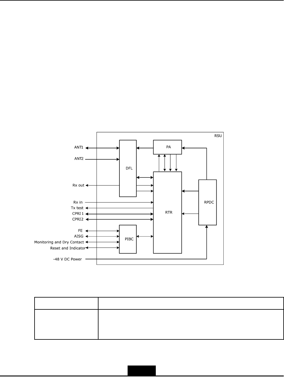
3.1SystemArchitecture
AZXSDRRSUCconsistsofthetransmit/receivesignalboard(RTR),poweramplier(PA),
duplexer(DFL),andpowersupply(RPDC).Figure3-1showstheschematicdiagramofthe
ZXSDRRSUC.
Figure3-1SchematicDiagramoftheZXSDRRSUC
ThefunctionsofZXSDRRSUC’ssubsystemisshownasT able3-1.
Table3-1Thefunctionsofsubsystem
PartDescription
RTR
RTR,theunitthatintegratestheprocessor,clock,CPRIinterface,DPD
digitalpredistortion,RFtransmittingandreceivingfunctions,isthecore
unitoftheZXSDRRSUC.
3-1
SJ-20101019140047-002|2012-03-15(R1.1)ZTEProprietaryandCondential

ZXSDRRSUCUserManual
PartDescription
PA
lAmpliesdownlinkRFsignalinputviatheRTRandthensendsthe
signaltotheDFL
lProvidesdigitalpre-distortionfeedbacksignalsfortheRTR
lProvidesaPAoutputenable/disableinterface
DFL
lPerformslteringandlownoiseamplicationofthereverseCDMA
signalfromtheantenna
lFilterstheforwardRFsignaltobesent
lReportsLNAalarmstotheRTR
lInthecaseofmain/diversitycombinedcabinets,themainreceiveLNA
outputendoftheDFLhasthepowersplitterfunctionandreserves
anexternalport(Rxout)
RPDC
Converts-48VDCinputpowersupplytoDCpowersupplyrequiredby
thePA,RTR,orDFL
3.2SignalProcessingFlow
TheinternalsignalprocessingowofZXSDRRSUCisasbelow:
lForwardlinkprocessing
ThebusinessdatafromBBUenterstheRTR,andthenforintermediatefrequency
processing.Afterthepoweramplicationsenttotheantennafortransmission.
lReverselinkprocessing
ThereverseCDMAsignalsfromtheantennaareconvertedtobasebanddigitalsignal
byRTR,thensendtoBBU.
3.3TechnicalSpecications
3.3.1PhysicalIndices
3.3.1.1Dimension
ThedimensionsofZXSDRRSUCinmmare:482.6(H)×88(W)×360.0(D).
3.3.1.2Weight
WeightofaZXSDRRSUC:<15kg(33.1pounds).
3.3.2Power
lPowerSupply
3-2
SJ-20101019140047-002|2012-03-15(R1.1)ZTEProprietaryandCondential
Chapter3TechnicalDescripition
-48VDCVoltagerange:-40V~-57V.
lPowerConsumption
Inthecaseof1S-1T ,4C/S,15W/C,thetotalpowerconsumptionoftheequipmentis
270W.
3.3.3CapacityIndices
ZXSDRRSUCCapacityIndicesisshownasT able3-2
Table3-2ZXSDRRSUCCapacityIndices
ItemCarrierssupported
18C1X
28CDO
3theMax8C/1S-1T
3.3.4TemperatureandHumidity
Temperature:-20℃~+45℃.Thechangefrequencymustbelessthan0.5℃/min.
Relativehumidity:5%~95%
3.3.5EnvironmentalClasses
lGradeOfProtection:IP30
lGroundingRequirements:Jointgroundingresistanceless1W;BTSgrounding
resistanceless5W.
lNoise:Noiseofworkingenvironment:less65dBA
3.3.6ReliabilityIndices
lMeanTimeBetweenFailures(MTBF):>100,000hours
lMTTR(MeanTimeT oRepair):<0.5hour
lAvailability:>99.999%
3.3.7RFIndices
RFindicesoftheZXSDRRSUCcomplywith3GPP2C.S0010-C,Recommended
MinimumPerformanceStandardsforcdma2000SpreadSpectrumBaseStationand
3GPP2C.S0032-A,RecommendedMinimumPerformanceStandardsforCDMA2000
HighRatePacketDataAccessNetwork.
Table3-3illustratesthe800MHztransmitterindices.
3-3
SJ-20101019140047-002|2012-03-15(R1.1)ZTEProprietaryandCondential
ZXSDRRSUCUserManual
Table3-3800MHzTransmitterIndices
NameIndex
Operatingband800MHz(BandClass0)
Transmitteroutputfrequencytolerance±0.01ppm
Occupiedchannelbandwidth1.23MHz(BandClass0)
OutputpowerattheTopofCabinet
(TOC)
60W
TotaltransmitpowerThetotaltransmitpoweriswithin+2dBand-2dBofthe
manufacturer’sratedpower.
ModulationmodeQuadratureamplitudemodulation
Conductedspuriousemissionand
radiatedspuriousemissionsuppression
<-45dBc@±750kHzoffsetCenterFreq(RBW30kHz)
<-60dBc@±1.98MHzoffsetCenterFreq(RBW30kHz)
>4MHzOFFSET:
<-36dBm(RBW1kHz)@9KHz<f<150KHz
<-36dBm(RBW10kHz)@150KHz<f<30MHz
<-30dBm(RBW1MHz)@1GHz<f<12.5GHz
4-6.4MHzOFFSET:
<-36dBm(RBW1kHz)@30MHz<f<1GHz
6.4MTO16MOFFSET :
<-36dBm(RBW10kHz)@30MHz<f<1GHz
>16MHzOFFSET:
<-36dBm(RBW100kHz)@30MHz<f<1GHz
Transmitterintermodulation
performance
IfoneBTStransmitsattheratedpowerbutanotherBTS’
outputpoweris30dBlessthantheformer’sratedpower.
WhenthepowersoftwoBTSsarecombinedontheantenna
port,thegeneratedintermodulationspuriousemission
meetstheconductedspuriousemissionrequirement.The
IFdifferenceofthetransmitsignalsoftwoBTSsis1.25M.
PilottimetoleranceThePNtimetolerancefallswithin3usandtheinter-carrier
tolerancefallswithin1us.
Timedifference:<±50nsTimeTolerance/phasetoleranceofpilot
channeltootherchannelsPhasedifference:<0.05rad
WaveformqualityRhoisgreaterthan0.970dBmwithcongurationofa
singlepilot.
PilotcodedomainpowerWiththestandard9CHconguration,thepilotcodedomain
powerisintherangeof-7.0±0.5dB.
InactivechannelcodedomainpowerWiththestandard9CHconguration,theinactivechannel
codedomainpowerislessthan-27dB.
3-4
SJ-20101019140047-002|2012-03-15(R1.1)ZTEProprietaryandCondential
Chapter3TechnicalDescripition
NameIndex
DOMACinactivechannelcodedomain
power
Withcongurationof13FLUSs,theMACinactivechannel
codedomainpowerislessthan-29.5dB(type2).
DODATAchannelcodedomainpowerWithcongurationof13FLUSsattherateof614.44kbs
(test1),theDATAchannelcodedomainpowerisinthe
rangeof-15.5dBto-14.5dB.
Pilotchannel:Rho>0.97
MACchannel:Rho>0.912
WavequalityofDOchannels
DATAchannel:Rho>0.97
RadiofrequencyFrontEndSWR<2.0
Table3-4illustratesthe1.9GHztransmitterindices.
Table3-41.9GHzTransmitterIndices
NameIndex
Operatingband1.9GHz(BandClass1)
Transmitteroutputfrequencytolerance±0.01ppm
Occupiedchannelbandwidth1.25MHz
OutputpowerattheT opofCabinet
(TOC)
60W
TotaltransmitpowerThetotaltransmitpoweriswithin+2dBand-2dBofthe
manufacturer’sratedpower.
ModulationmodeQuadratureamplitudemodulation
Conductedspuriousemissionand
radiatedspuriousemissionsuppression
<-45dBc@±885kHzoffsetCenterFreq(RBW30kHz)
<-55dBc@±1.98MHzoffsetCenterFreq(RBW30kHz)
>4MHzOFFSET:
<-36dBm(RBW1kHz)@9KHz<f<150kHz
<-36dBm(RBW10kHz)@150kHz<f<30MHz
<-36dBm(RBW100kHz)@30MHz<f<1GHz
4-16MHzOFFSET:
<-30dBm(RBW30kHz)@1GHz<f<12.5GHz
16M-19.2MOFFSET:
<-30dBm(RBW300kHz)@1GHz<f<12.5GHz
>19.2MHzOFFSET:
<-30dBm(RBW1MHz)@1GHz<f<12.5GHz
3-5
SJ-20101019140047-002|2012-03-15(R1.1)ZTEProprietaryandCondential

ZXSDRRSUCUserManual
NameIndex
Transmitterintermodulation
performance
IfoneBTStransmitsattheratedpowerbutanotherBTS’
outputpoweris30dBlessthantheformer’sratedpower.
WhenthepowersoftwoBTSsarecombinedontheantenna
port,thegeneratedintermodulationspuriousemission
meetstheconductedspuriousemissionrequirement.The
IFdifferenceofthetransmitsignalsoftwoBTSsis1.25M.
PilottimetoleranceThePNtimetolerancefallswithin3usandtheinter-carrier
tolerancefallswithin1us.
Timedifference:<±50nsTimeTolerance/phasetoleranceofpilot
channeltootherchannelsPhasedifference:<0.05rad
WaveformqualityRhoisgreaterthan0.990dBmunderthecongurationof
asinglepilot.
PilotcodedomainpowerWiththestandard9CHconguration,thepilotcodedomain
powerisintherangeof-7.0±0.5dB.
InactivechannelcodedomainpowerWiththestandard9CHconguration,theinactivechannel
codedomainpowerislessthan-27dB.
DOMACinactivechannelcodedomain
power
Withcongurationof13FLUSs,theMACinactivechannel
codedomainpowerislessthan-29.5dB(type2).
DODATAchannelcodedomainpowerWithcongurationof13FLUSsattherateof614.44kbs
(test1),theDATAchannelcodedomainpowerisinthe
rangeof-15.5dBto-14.5dB.
Pilotchannel:Rho>0.97
MACchannel:Rho>0.912
WavequalityofDOchannels
DATAchannel:Rho>0.97
RadiofrequencyFrontEndSWR<2.0
Table3-5illustratesthe800MHzreceiverindices.
Table3-5800MHzReceiverIndices
NameIndex
Operatingband800MHz(BandClass0)
Receiversensitivity<-115dBm
ReceiverdynamicrangeWhenthelowerlimitisthereceiversensitivityandthe
upperlimit(noiselevel)equals55dBm/1.23MHz(Eb/N0=
10dB±1dB),theFrameErrorRate(FER)islowerthan1%.
Noisegure<3
3-6
SJ-20101019140047-002|2012-03-15(R1.1)ZTEProprietaryandCondential
Chapter3TechnicalDescripition
NameIndex
SingletonedesensitizationInthepresenceofasingletonethatis50dBabovethe
CDMAsignallevel,andisatoffsetof±750kHzfromthe
centerfrequency,theoutputpoweroftheMSincreasesby
nomorethan3dB,andtheFERislessthan1.5%.
Inthepresenceofasingletonethatis75dBabovethe
CDMAsignallevel,andisatoffsetof±900kHzfromthe
centerfrequency,theoutputpoweroftheMSincreasesby
nomorethan3dB,andtheFERislessthan1.5%.
Intermodulationspuriousresponse
attenuation
BAND0:
Inthepresenceoftwointerferingtonesthatare60dB
abovetheCDMAsignallevel,andareatoffsetsof+900
kHz,+1.7MHz,-900kHzand-1.7MHzfromthecenter
frequency,theoutputpoweroftheMSincreasesbyno
morethan3dB,andtheFERislessthan1.5%.
Conductedspuriousemissionsand
radiatedspuriousemissions
<-80dBm,measuredwithintheBTSreceiveband
<-60dBm,measuredwithintheBTStransmitband
RadiofrequencyFrontEndSWR<2.0
Table3-6illustratesthe1.9GHzreceiverindices.
Table3-61.9GHzReceiverIndices
NameIndex
Operatingband1.9GHz(BandClass1&14)
Receiversensitivity<-115dBm
ReceiverdynamicrangeWhenthelowerlimitisthereceiversensitivityandtheupper
limit(noiselevel)equals-55dBm/1.23MHz(Eb/N0=
10dB±1dB),theFrameErrorRate(FER)islowerthan1%.
Noisegure<3
Adjacentchannelselection(ACS)BandClass6:>-53dBm(±2.5M)
SingletonedesensitizationInthepresenceofasingletonethatis50dBabovethe
CDMAsignallevel,andisatoffsetof±750kHzfromthe
centerfrequency,theoutputpoweroftheMSincreasesby
nomorethan3dB,andtheFERislessthan1.5%.
Inthepresenceofasingletonethatis75dBabovethe
CDMAsignallevel,andisatoffsetof±900kHzfromthe
centerfrequency,theoutputpoweroftheMSincreasesby
nomorethan3dB,andtheFERislessthan1.5%.
3-7
SJ-20101019140047-002|2012-03-15(R1.1)ZTEProprietaryandCondential
ZXSDRRSUCUserManual
Intermodulationspuriousresponse
attenuation
Inthepresenceoftwointerferingtonesthatare60dB
abovetheCDMAsignallevel,andareatoffsetsof1.25
MHzand2.05MHz,and-1.25MHzand-2.05MHzfrom
thecenterfrequency,theoutputpoweroftheMSincreases
bynomorethan3dB,andtheFERislessthan1.5%.
Conductedspuriousemissionsand
radiatedspuriousemissions
<-80dBm,measuredwithintheBTSreceiveband
<-60dBm,measuredwithintheBTStransmitband
RadiofrequencyFrontEndSWR<2.0
3.3.8InterfaceIndices
TheinterfaceindicesofZXSDRRSUCisshownasT able3-7.
Table3-7DescriptionofZXSDRRSUC’sinterfaces
TypeDescriptionIndex
CPRIFiber/Cable2CPRIinterfaces:1CPRIforBBUor
upper-levelRSU1CPRIforlower-levelRSU
UEUminterface1Tx/Rx1diversityreceivers
3-8
SJ-20101019140047-002|2012-03-15(R1.1)ZTEProprietaryandCondential

Chapter4
HardwareDecsripition
TableofContents
Function.....................................................................................................................4-1
Panel..........................................................................................................................4-1
Button........................................................................................................................4-2
Indicators...................................................................................................................4-3
PanelInterfaces.........................................................................................................4-3
4.1Function
RSUprovidesthefollowingfunctions:
lCommunicationwiththebasebandsubrack
lConversionbetweenairinterfaceRFsignalsanddigitalsignals
lRFsignalamplication,transmission,andreception
lClocksynchronization.
4.2Panel
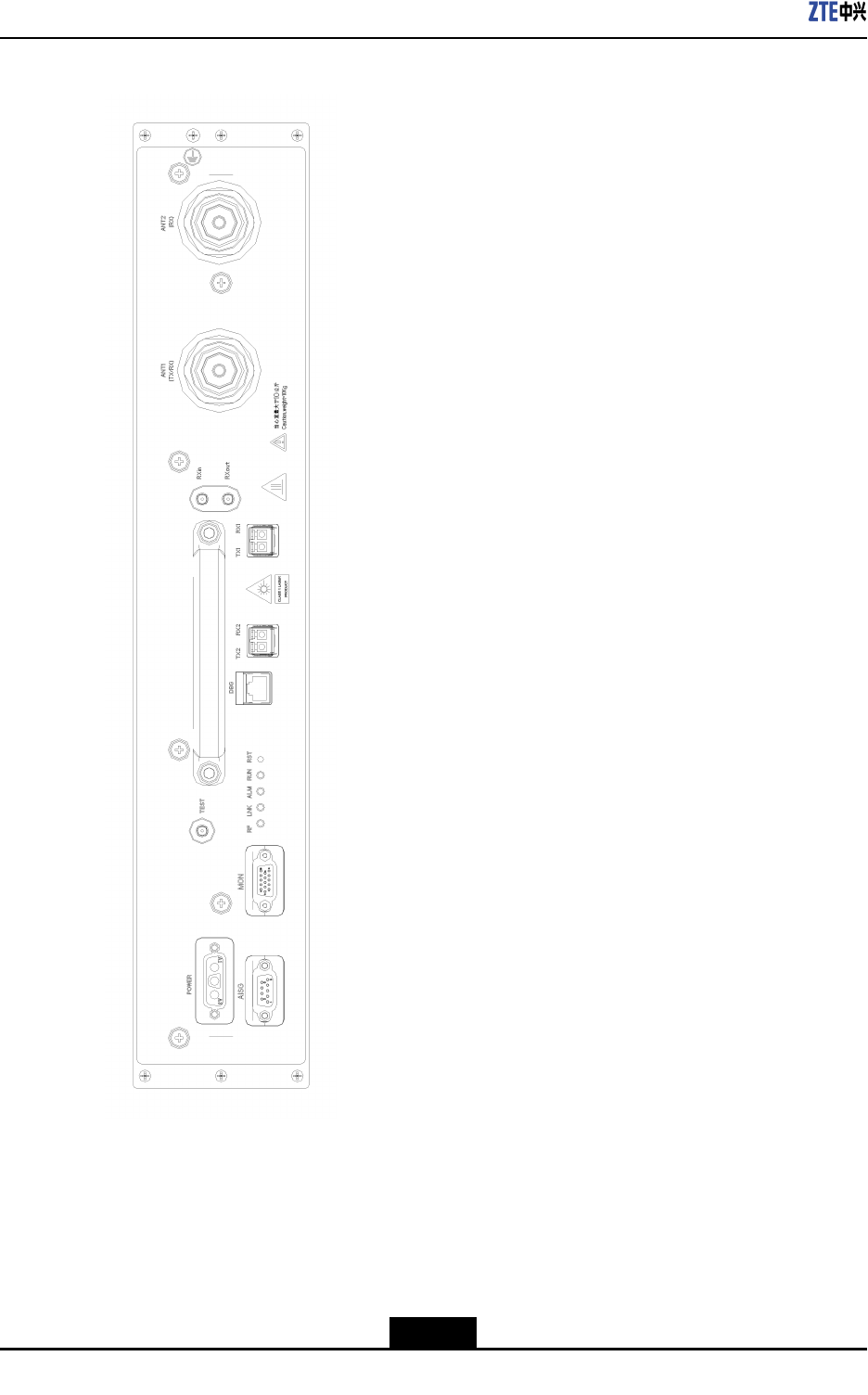
Figure4-1illustratestheZXSDRRSUCpanel.
4-1
SJ-20101019140047-002|2012-03-15(R1.1)ZTEProprietaryandCondential

Chapter4HardwareDecsripition
Table4-1ZXSDRRSUCPanelButtonDescription
ButtonDescription
RSTResetbutton
4.4Indicators
Table4-2describesZXSDRRSUCpanelindicators.
Table4-2ZXSDRRSUCPanelIndicatorDescription
IndicatorColorMeaningDescription
RUNGreenRunningstatus
indicator
Alwayson:TheRSUisresettingorstartingup.
Blinkingat1Hz:TheRSUisfunctioningproperly.
Blinkingat5Hz:TheRSUisdownloadingversion
les.
Off:TheRSUfailstheself-check.
ALMRedAlarmindicatorOff:ThereisonalarmortheRSUisresetting,
startingup,ordownloadingversionles.
Blinkingat5Hz:Thereisacriticalalarm.
Blinkingat1Hz:Thereisaminoralarm.
LNKGreenOpticallinkstatus
indicator
Alwayson:Theopticalconnectionisnormal.
Off:Theopticalberfails.
Blinkingat5Hz:Thislinkisusedastheclock
referencesourceandthephaselockloop(PLL)is
inthefastcapturestate.
Blinkingat0.25Hz:Thislinkisusedastheclock
referencesourceandthephaselockloop(PLL)is
inthetracingstate.
RFOrangeRFworking
statusindicator
Off:TheRFhasnooutput.
On:TheRFhasoutput.
4.5PanelInterfaces
Table4-3describesZXSDRRSUCpanelinterfaces.
Table4-3InterfacesontheFrontPaneloftheZXSDRRSUC
InterfaceEndAEndBDescription
ANT1(TX/RX)RSUTx/RxantennaConnectstotheTx/RxantennafortheTx/Rx
majorchannel.
ANT2(RX)RSURxantennaConnectstotheantennalfortheRxminorantenna
4-3
SJ-20101019140047-002|2012-03-15(R1.1)ZTEProprietaryandCondential

ZXSDRRSUCUserManual
InterfaceEndAEndBDescription
RxoutRSURSUwithexpanded
frequencypoints
Frequency-pointexpansionoutputinterfacefor
outputtingtheRxsignalsofthemajorchannel.
RxinRSUwith
expanded
frequency
points
RSUFrequency-pointexpansioninputinterfacefor
inputtingtheRxsignalsoftheminorchannel.
TX1/RX1RSUBBUortheupper-layer
cascadedRSU
ConnectstotheCPRIopticalinterfaceofBBUor
theupper-layercascadedRSU
TX2/RX2RSULower-layercascaded
RSU
ConnectstotheCPRIopticalinterfaceofthe
lower-layercascadedRSU
DBGRSUPCortestingequipment
(withathetesting
board)
CommissioningEthernetinterfaceandtesting
interface
TESTRSUTestingequipmentTxtestingsignalinterface
MONRSUExternalequipmentProvidesfourdry-contactinputinterfacesand
RS-485environmentmonitoringinterface
AISGRSUAntennaConnectstotheAISGinterface
POWERRSURFpowerofthepower
distributionmodule
Powerinputinterface
4-4
SJ-20101019140047-002|2012-03-15(R1.1)ZTEProprietaryandCondential

Chapter5
HardwareInstallation
TableofContents
InstallingtheRSUModule..........................................................................................5-1
ConnectingRSUMonitoringCable.............................................................................5-9
InstallingOpticalFibersBetweenBBUandRSU......................................................5-10
InstallingtheInterconnectedCableBetweenBBUandRSU.....................................5-12
InstallingtheRFJumper...........................................................................................5-15
5.1InstallingtheRSUModule
Prerequisite
lBeforeinstallingtheRFmodule,weartheESDwriststraptoavoiddamagingtheRF
module.
lTheRFcabinethasalreadybeeninstalled.
Context
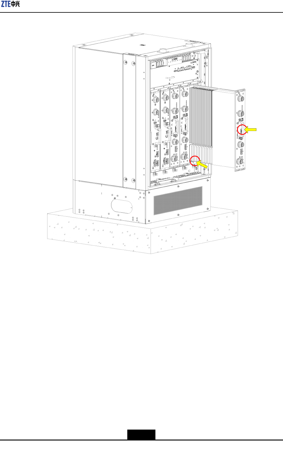
Figure5-1showsthefrontpanelofaZXSDRRSUC.
5-1
SJ-20101019140047-002|2012-03-15(R1.1)ZTEProprietaryandCondential
Chapter5HardwareInstallation
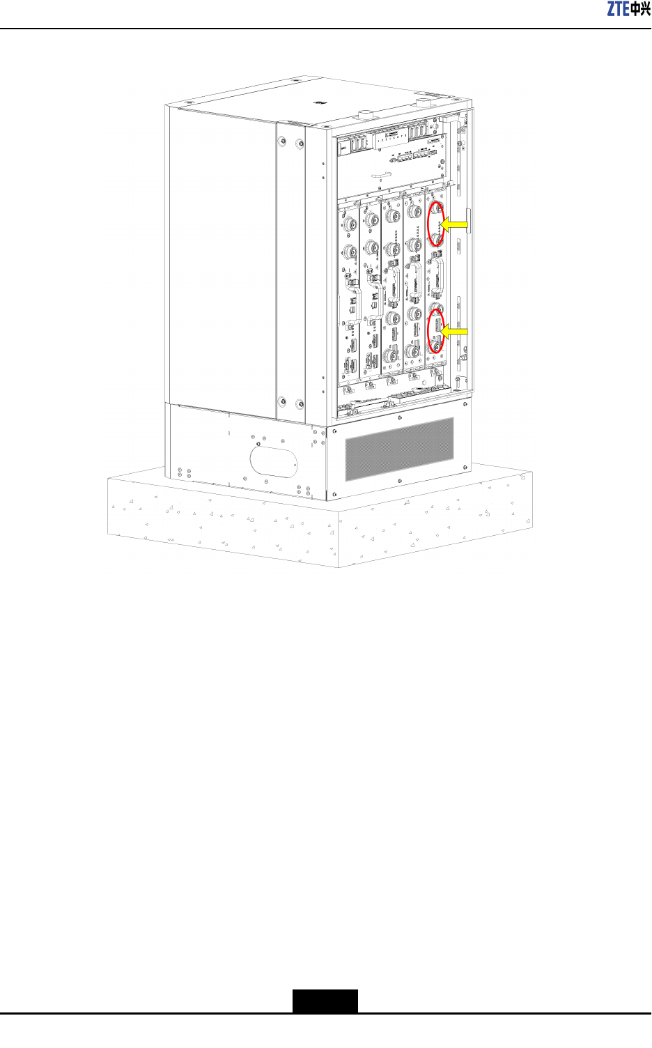
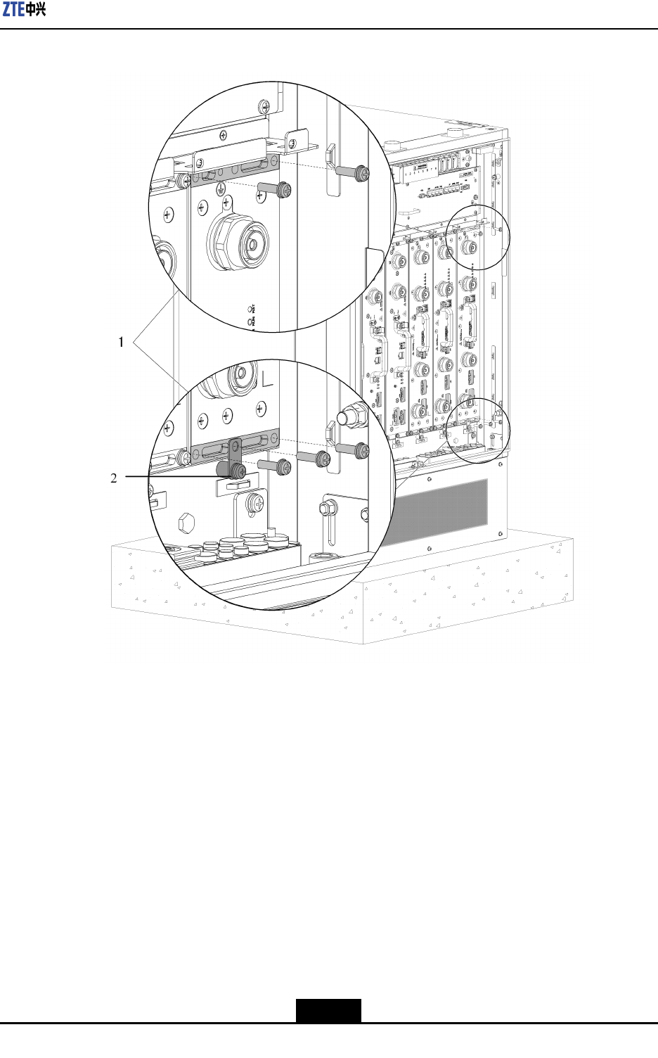
Figure5-6Step5
1.Fixingthecabinetwith
5M5x20screws
2.Fixingthegrounding
lug
6.Securethegroundlug.
AsshowninFigure5-6,theM5x20screwssecuresthegroundlugoftheRSUmodule
tothegroundpoints.
–EndofSteps–
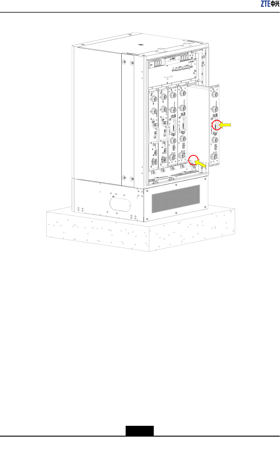
Result
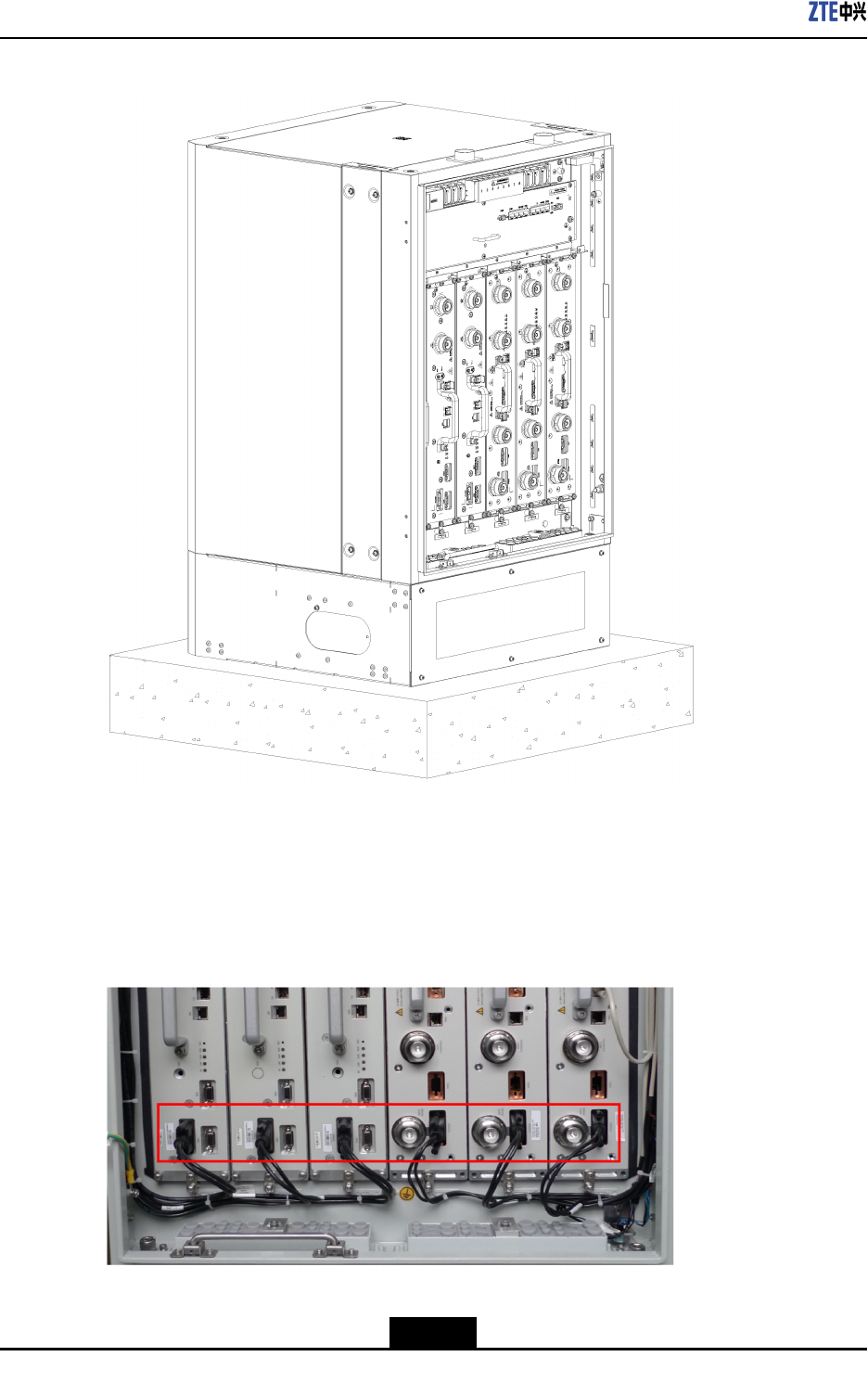
Figure5-7showsthecompletionofinstallingtheRFmodule.
5-7
SJ-20101019140047-002|2012-03-15(R1.1)ZTEProprietaryandCondential
ZXSDRRSUCUserManual
Figure5-7RSUModuleInstalledCompletely
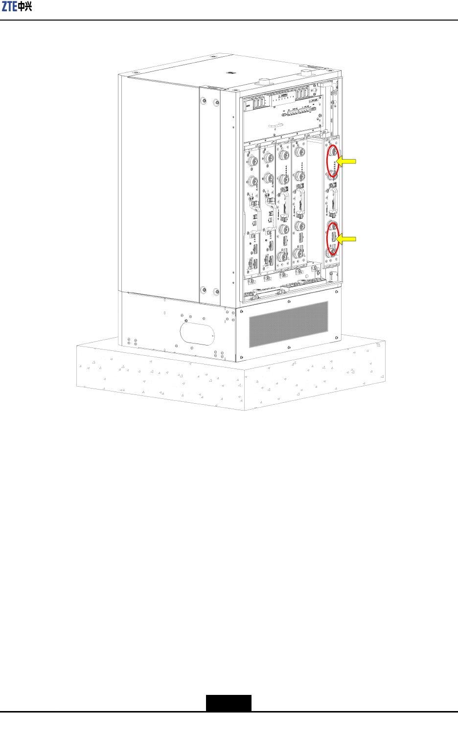
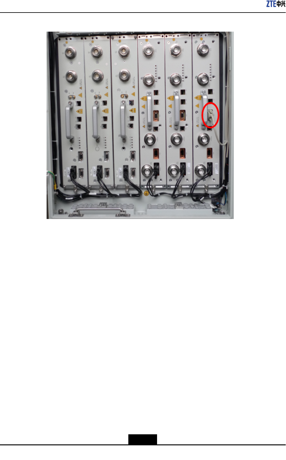
Follow-UpAction
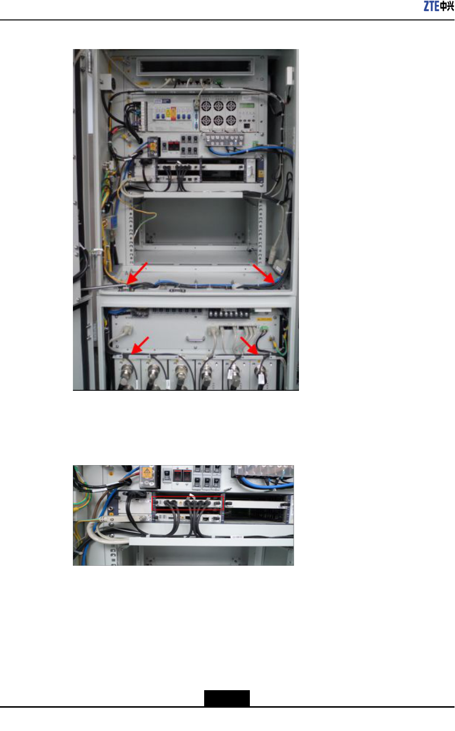
AfterinstallingRSUmodules,connecttheRSUpowercablestotheRSUpower
interfaces.RSUpowercableshavebeenroutedtoproperslots,asshowninFigure5-8.
Figure5-8PowerCableConnectingtheRSU
5-8
SJ-20101019140047-002|2012-03-15(R1.1)ZTEProprietaryandCondential
Chapter5HardwareInstallation
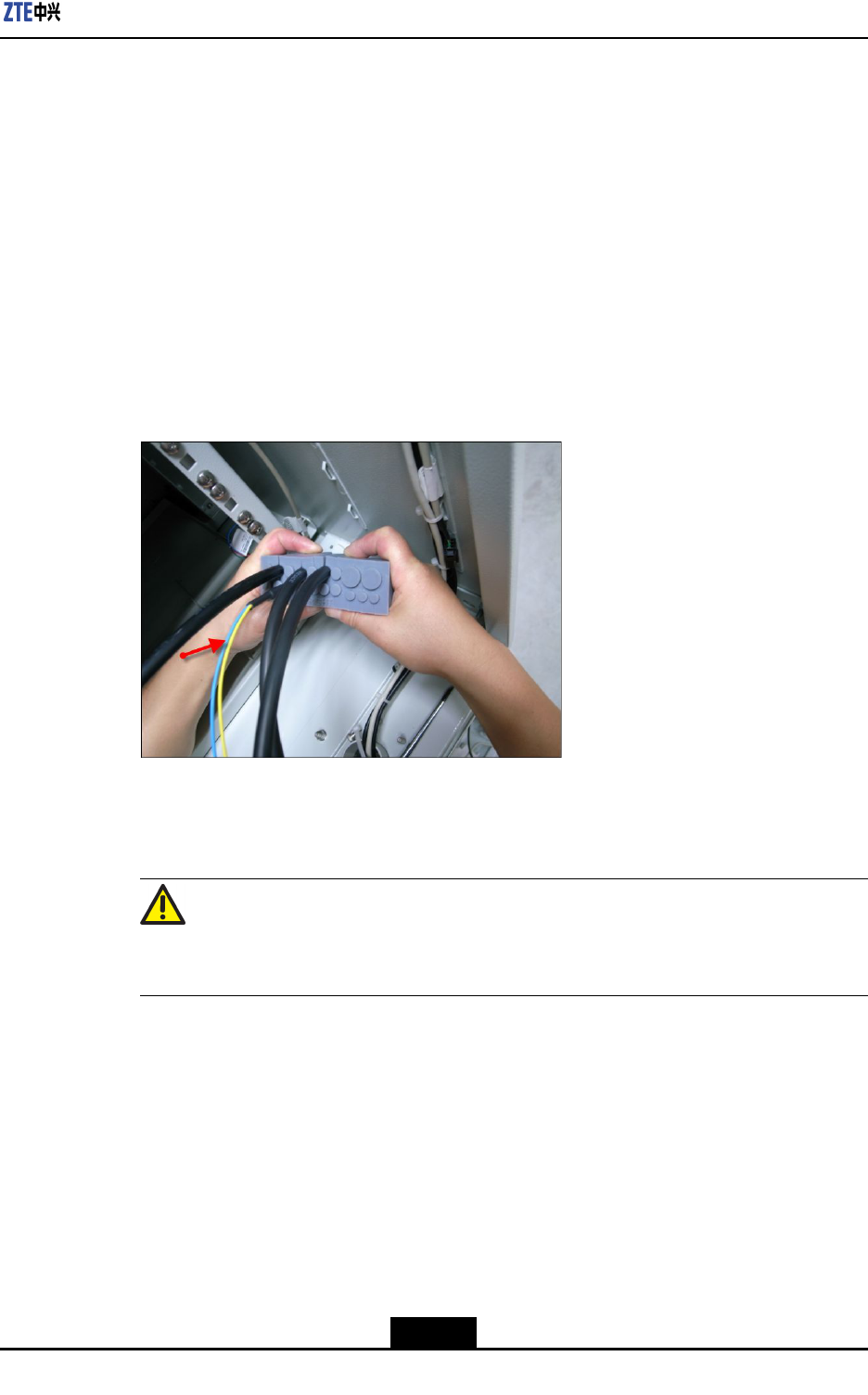
5.2ConnectingRSUMonitoringCable
Prerequisite
lZXSDRRSUCRFcabinethasalreadybeeninstalled.
lTheRSUmodulehasalreadybeeninstalled.
Context
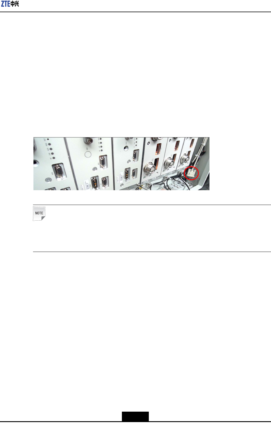
TheRSUmonitoringcableoftheRFcabinetisroutedtotherightsideoftheRFcabinet
indelivery,asshowninFigure5-9.AftertheRSUmoduleisinstalled,inserttheterminal
oftheRSUmonitoringcabletotheMON(monitoring)interfaceoftheRSUmodule.
Figure5-9RSUMonitoringCable
Note:
IfmultipleRSUmodulesneedtobemonitored,onlyoneRSUmoduleneedstobe
connectedtotheRSUmonitoringcable.
Steps
1.ConnectoneendoftheRSUmonitoringcabletotheMON(monitoring)interfaceof
theRSUmoduleandfastenthescrew.
2.BundletheRSUmonitoringcable.
Figure5-10showstheconnectedRSUmonitoringcable.
5-9
SJ-20101019140047-002|2012-03-15(R1.1)ZTEProprietaryandCondential
ZXSDRRSUCUserManual
Figure5-10InstallingtheRSUMonitoringCable
–EndofSteps–
5.3InstallingOpticalFibersBetweenBBUandRSU
Prerequisite
lTheESDwriststrapmustbeworn.
lThebasebandpowercabinetandtheRFcabinethavebeenindependentlyinstalled.
Context
WhenthebasebandpowercabinetandtheRFcabinetareinstalledsidebysideorthey
arefarawayfromeachother,youneedtoconnectBBUandRSUusingopticalbers.
Payattentiontothefollowingpointswheninstallingopticalbers:
lDonotdamagetheopticalbercladdingduringoperations.
lProtectopticalberconnectorsandavoidcontaminatingthem.
lDonotforciblybundleopticalbers.
lCurveopticalbersattheturning.
Steps
1.Afxatemporarylabel.
5-10
SJ-20101019140047-002|2012-03-15(R1.1)ZTEProprietaryandCondential
Chapter5HardwareInstallation
Afxtemporarylabelstobothendsofthenewopticalbertosetupamapping.If
morethanoneopticalberneedstobeinstalled,usedifferentlabelstodifferentiate
opticalbers.
2.Routeopticalbers.
a.Opticalbersgooutfromthesidewaterproofmoduleofthebasebandmoduleand
gothroughtheroutingaperturesonthebase.
b.Then,opticalbersgothroughtheroutingaperturesonthebaseoftheRFcabinet,
traversethewaterproofmodules,andconnecttothesixopticalinterfacesforRF
modules.
Figure5-11showshowopticalberstraversethewaterproofmodules.
Figure5-11WaterproofModulethroughWhichOpticalFibersPass
3.Insertopticalberconnectors.
Insertopticalberconnectorsaccordingtothemappingontemporarylabels.
Caution!
Insertopticalberconnectorstightly.
4.Bundleopticalbers.
Bundleandsecureopticalbersalongtheroutingtroughs,whichcomplieswith
relevantregulations.
5.Afxanengineeringlabeltoanopticalber.
Removethetemporarylabelfortheopticalberandafxanengineeringlabel.
5-11
SJ-20101019140047-002|2012-03-15(R1.1)ZTEProprietaryandCondential
ZXSDRRSUCUserManual
Caution!
Protectanopticalberwiththewindingtubewhenroutingtheopticalberinsidethe
cabinet.Protectanopticalberwiththecorrugatedpipewhenroutingtheopticalber
outsidethecabinet.
–EndofSteps–
5.4InstallingtheInterconnectedCableBetweenBBU
andRSU
Prerequisite
lTheZXSDRRSUCcabinethasalreadybeeninstalled.
lTheBBUmoduleandRSUmodulehavealreadybeeninstalled.
Context
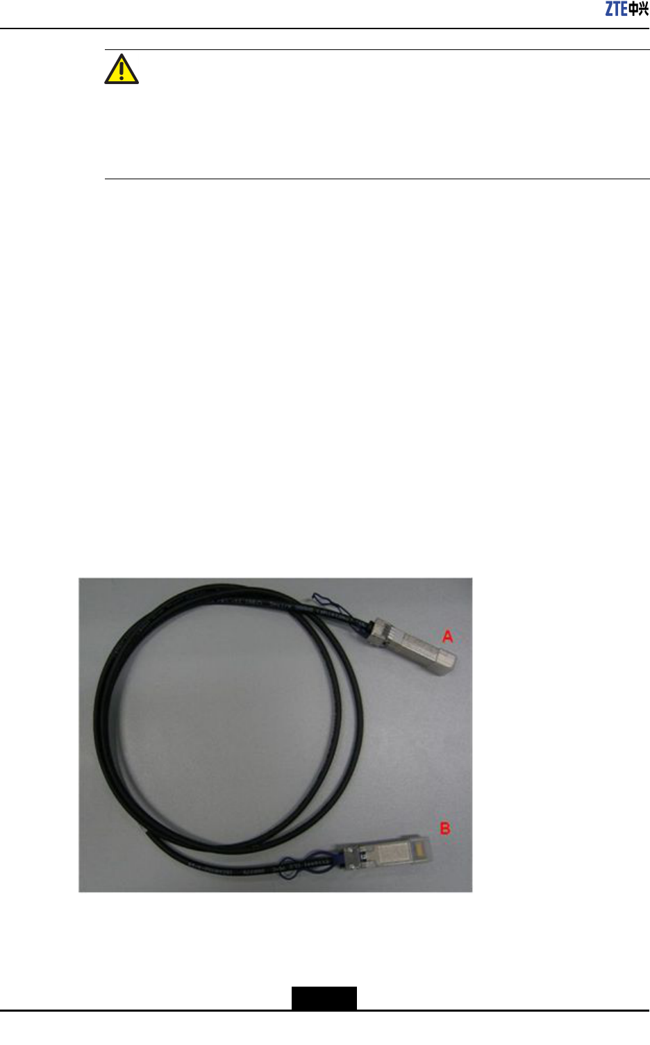
ZXSDRRSUCInthesystem,opticalbersorSFPcablescanbeusedtoconnectBBUand
RSU.DuringthestackedinstallationoftheZXSDRRSUC,a2mSFPhigh-speedcable
isrecommendedforinterconnectingBBUandRSU.Figure5-12showsanSFPcable.
Figure5-12High-SpeedCable
5-12
SJ-20101019140047-002|2012-03-15(R1.1)ZTEProprietaryandCondential
Chapter5HardwareInstallation
Steps
1.AfxtemporarylabelstobothendsoftheSFRcable,withmarkings0-5tosetup
one-to-onemappingwithinterfacesTX0RX0toTX5RX5ofBBUandsixTX/RX
interfacesofRSU.
2.InsertoneendoftheSFPcabletoaTX/RXinterfaceofRSU.
3.RoutetheSFPcablealongtheroutingtroughandcabinetsidestotheFSmoduleof
BBU.TheSFPcablesconnectingtotheRSUsinslots1to3ontheRFcabinetgo
throughtheleftroutingaperturesandthoseSFPcablesgothroughtherightapertures
ifconnectingtoslots4to6ontheRFcabinet,asshowninFigure5-13andFigure
5-14.
Figure5-13LayoutoftheSFPCablesintheRFCabinet
5-13
SJ-20101019140047-002|2012-03-15(R1.1)ZTEProprietaryandCondential
ZXSDRRSUCUserManual
Figure5-14SFPCableLayout
4.InsertSFPcablesintotheinterfacesTX0RX0toTX5RX5oftheBBUFSboard
accordingtothemarkings0-5,asshowninFigure5-15.
Figure5-15FSBoardConnectingtotheBBU
5.BundleSFPcables.
6.Removetemporarylabelsandafxengineeringlabels.
–EndofSteps–
5-14
SJ-20101019140047-002|2012-03-15(R1.1)ZTEProprietaryandCondential
Chapter5HardwareInstallation
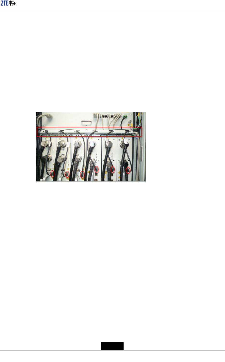
5.5InstallingtheRFJumper
Prerequisite
TheZXSDRRSUCRFcabinetandothermoduleshavealreadybeeninstalled.
Context
TheRFjumpersforthethreeZXSDRRSUCgothroughthewaterproofmoduleonthe
right.
RemovethefrontbafeofthebasebeforeinstallingtheRFjumpersandreseatthefront
bafeafteralljumpersarecompletelyinstalled.
Steps
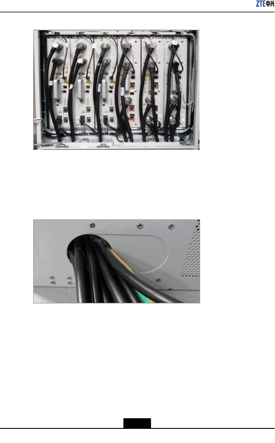
1.ConnecttheRFjumperstoANT1andANT2interfacesofRSUfromlefttoright.
2.WearthewaterproofrubberplugaftereverytwoRFjumpersareinstalled.
3.Insertthehorizontalandlongitudinalslideblocksandusethehexagonringwrenchto
fastenthem.
Caution!
Clampthewaterproofrubberplugtightlyandmakesurethattheunusedcabling
aperturewearstheplug.
4.RepeattheprecedingstepstoinstallotherRSU-relatedjumpers.
–EndofSteps–
Result
Figure5-16showsthecompletionofinstallingtheRFjumpers.
5-15
SJ-20101019140047-002|2012-03-15(R1.1)ZTEProprietaryandCondential
ZXSDRRSUCUserManual
Figure5-16AntennaFeederJumperInstalledCompletely
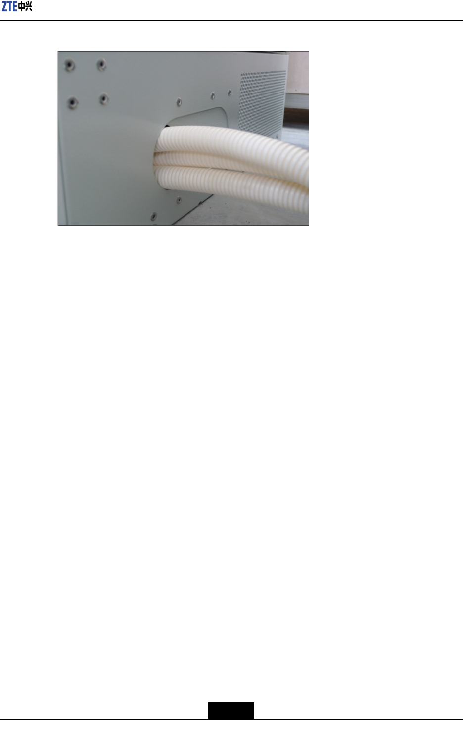
TheRFjumpersgooutfromthebase,asshowninFigure5-17.Thecablesbetween
cabinetsmustbeprotectedwithprotectivetubes,withoutanyexposedpartofthecables
andtheopeningsattwoendsofthesecablesmustbesealed,asshowninFigure5-18.
Figure5-17Lead-OutoftheAntennaFeederJumper
5-16
SJ-20101019140047-002|2012-03-15(R1.1)ZTEProprietaryandCondential
Chapter5HardwareInstallation
Figure5-18CablesinTubes
5-17
SJ-20101019140047-002|2012-03-15(R1.1)ZTEProprietaryandCondential

ZXSDRRSUCUserManual
Thispageintentionallyleftblank.
5-18
SJ-20101019140047-002|2012-03-15(R1.1)ZTEProprietaryandCondential

Figures
Figure2-1ZXSDRRSUCPositioninaNetwork.......................................................2-2
Figure2-2OuterViewofZXSDRRSUC...................................................................2-3
Figure3-1SchematicDiagramoftheZXSDRRSUC................................................3-1
Figure4-1ZXSDRRSUCPanel...............................................................................4-2
Figure5-1ZXSDRRSUCPanel...............................................................................5-2
Figure5-2Step1......................................................................................................5-3
Figure5-3Step2......................................................................................................5-4
Figure5-4Step3......................................................................................................5-5
Figure5-5Step4......................................................................................................5-6
Figure5-6Step5......................................................................................................5-7
Figure5-7RSUModuleInstalledCompletely............................................................5-8
Figure5-8PowerCableConnectingtheRSU...........................................................5-8
Figure5-9RSUMonitoringCable.............................................................................5-9
Figure5-10InstallingtheRSUMonitoringCable.....................................................5-10
Figure5-11WaterproofModulethroughWhichOpticalFibersPass........................5-11
Figure5-12High-SpeedCable................................................................................5-12
Figure5-13LayoutoftheSFPCablesintheRFCabinet........................................5-13
Figure5-14SFPCableLayout................................................................................5-14
Figure5-15FSBoardConnectingtotheBBU.........................................................5-14
Figure5-16AntennaFeederJumperInstalledCompletely......................................5-16
Figure5-17Lead-OutoftheAntennaFeederJumper.............................................5-16
Figure5-18CablesinTubes...................................................................................5-17
I

Figures
Thispageintentionallyleftblank.

Tables
Table1-1SafetySymbolsDescription.......................................................................1-2
Table2-1ThePrimaryFunctionsofZXSDRRSUC...................................................2-4
Table3-1Thefunctionsofsubsystem.......................................................................3-1
Table3-2ZXSDRRSUCCapacityIndices................................................................3-3
Table3-3800MHzTransmitterIndices.....................................................................3-4
Table3-41.9GHzTransmitterIndices......................................................................3-5
Table3-5800MHzReceiverIndices.........................................................................3-6
Table3-61.9GHzReceiverIndices..........................................................................3-7
Table3-7DescriptionofZXSDRRSUC’sinterfaces..................................................3-8
Table4-1ZXSDRRSUCPanelButtonDescription...................................................4-3
Table4-2ZXSDRRSUCPanelIndicatorDescription................................................4-3
Table4-3InterfacesontheFrontPaneloftheZXSDRRSUC...................................4-3
III

Tables
Thispageintentionallyleftblank.

Glossary
BBU
-BaseBandUnit
BS
-BaseStation
BSC
-BaseStationController
BTS
-BaseTransceiverStation
CDMA
-CodeDivisionMultipleAccess
CPRI
-CommonPublicRadioInterface
MS
-MobileStation
RF
-RadioFrequency
RSSI
-ReceivedSignalStrengthIndicator
RSU
-RFSystemUnit
SDR
-SoftwareDenedRadio
V