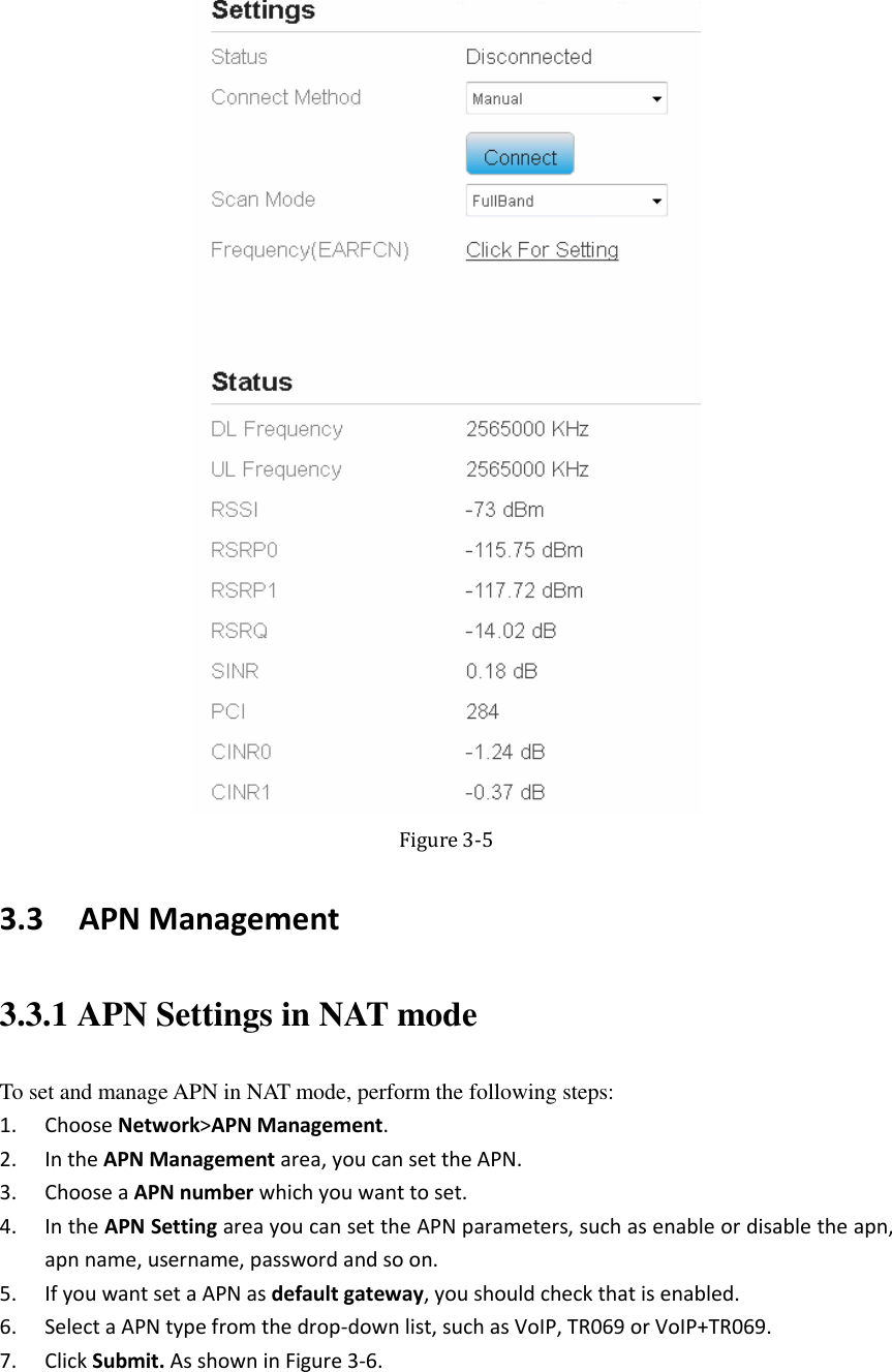
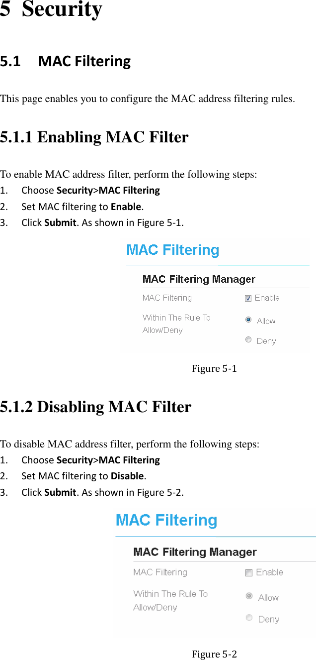
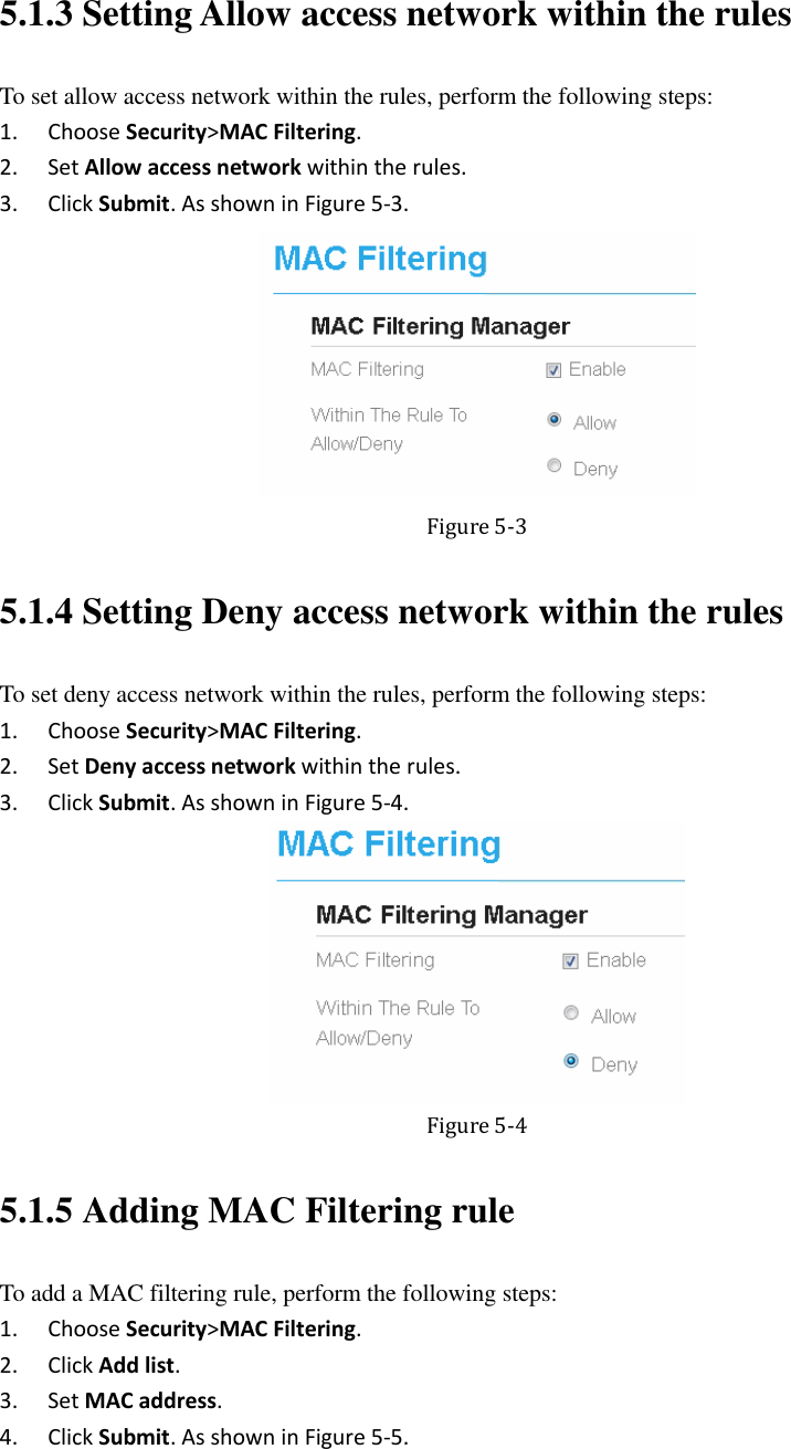
ZTE WF820R Wi-Fi Router User Manual
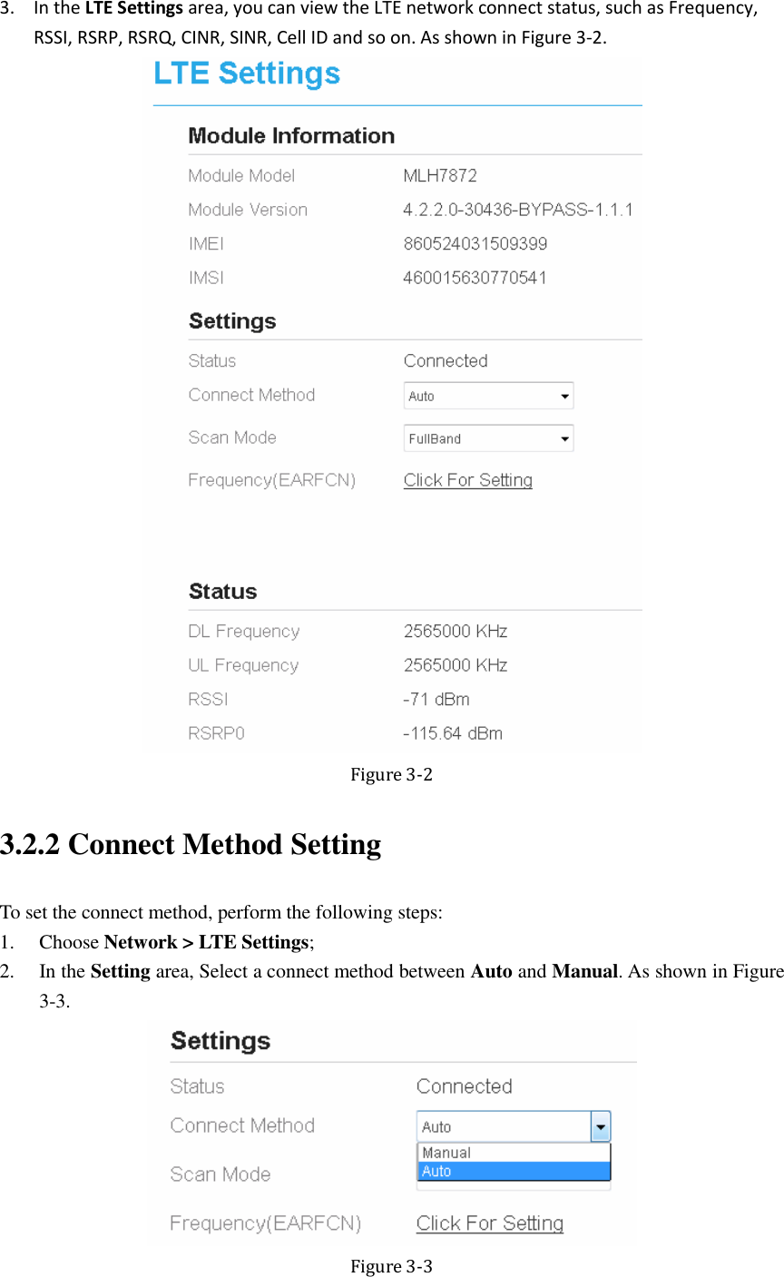
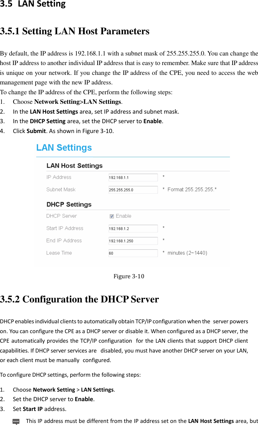
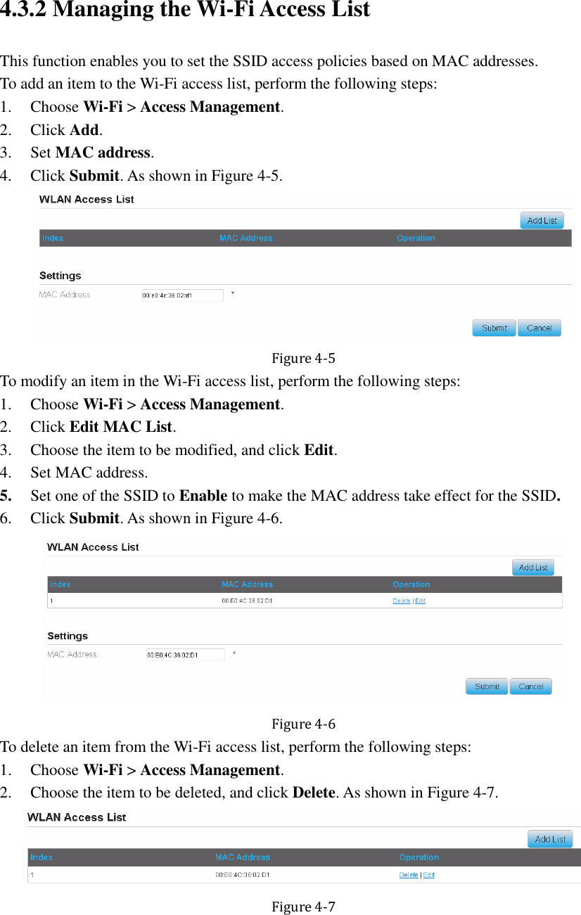
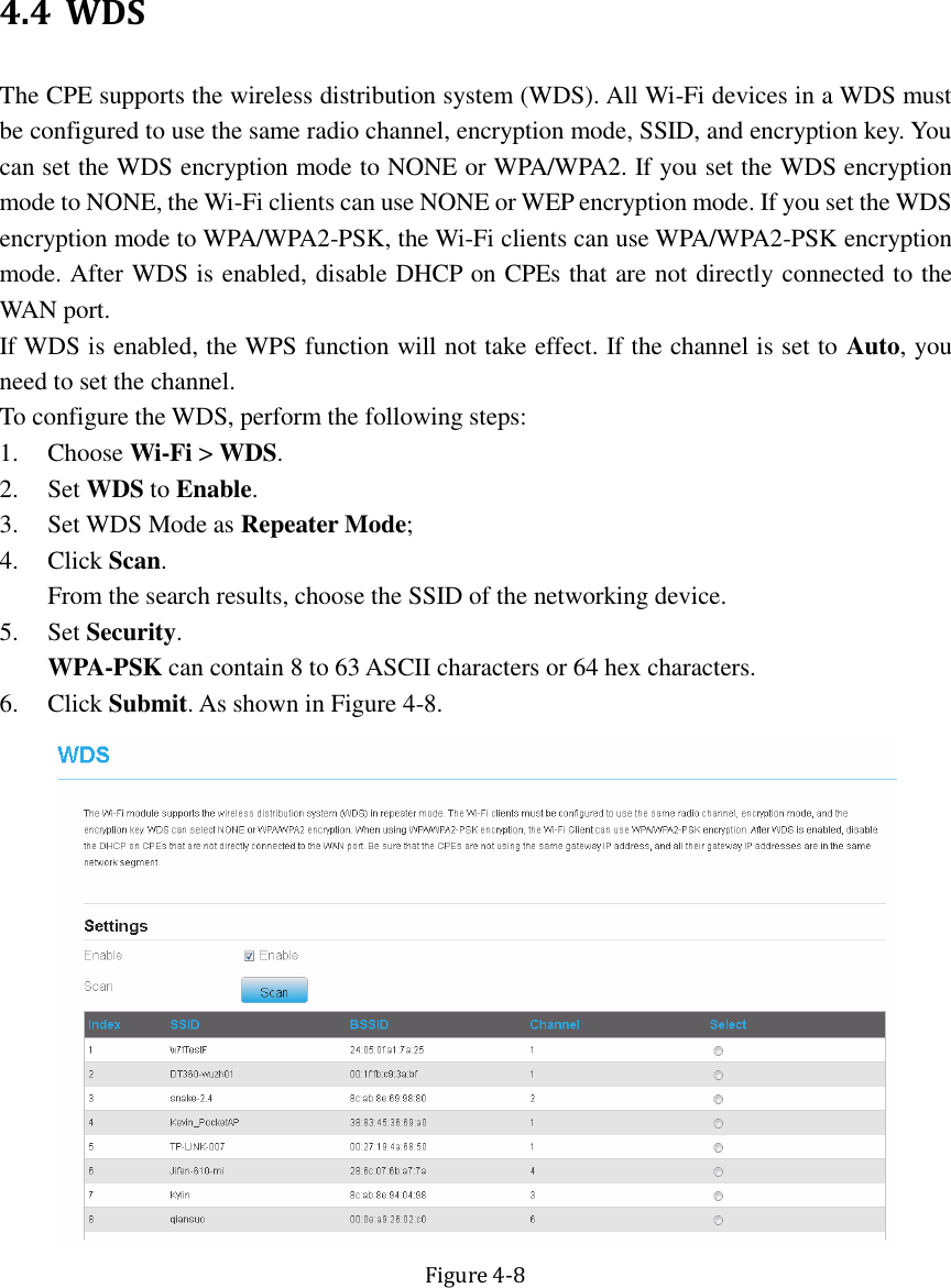
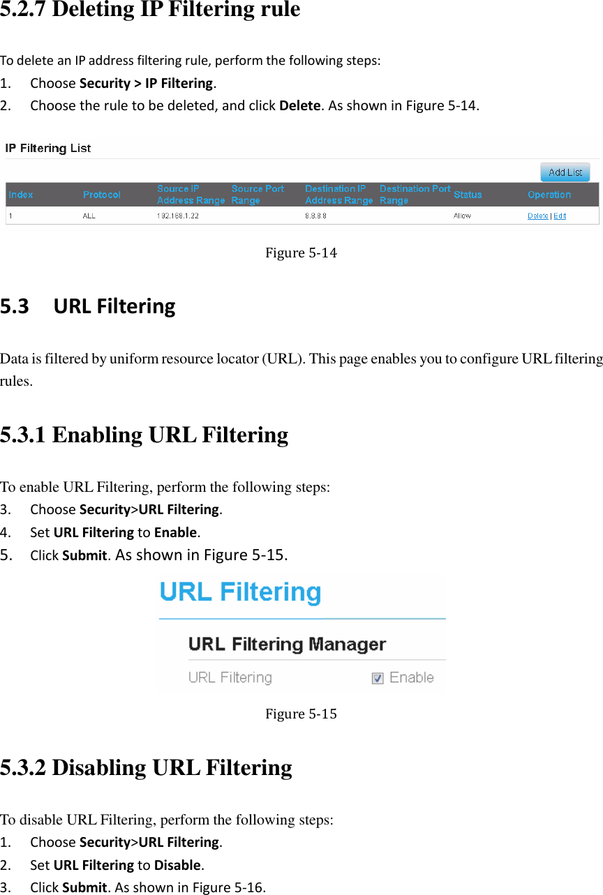
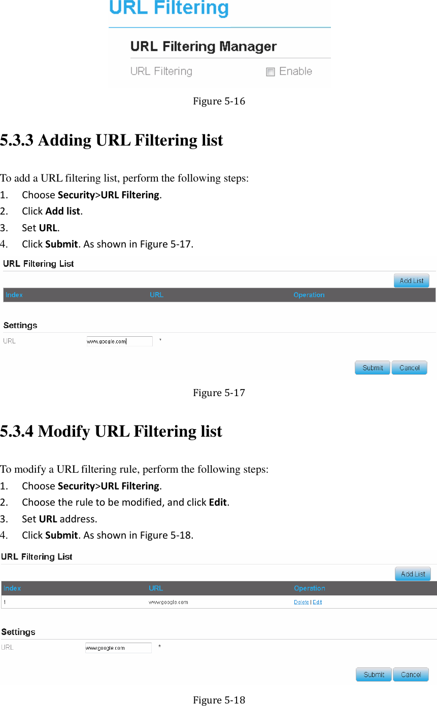
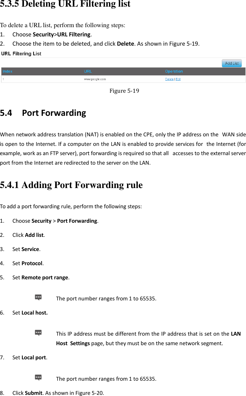
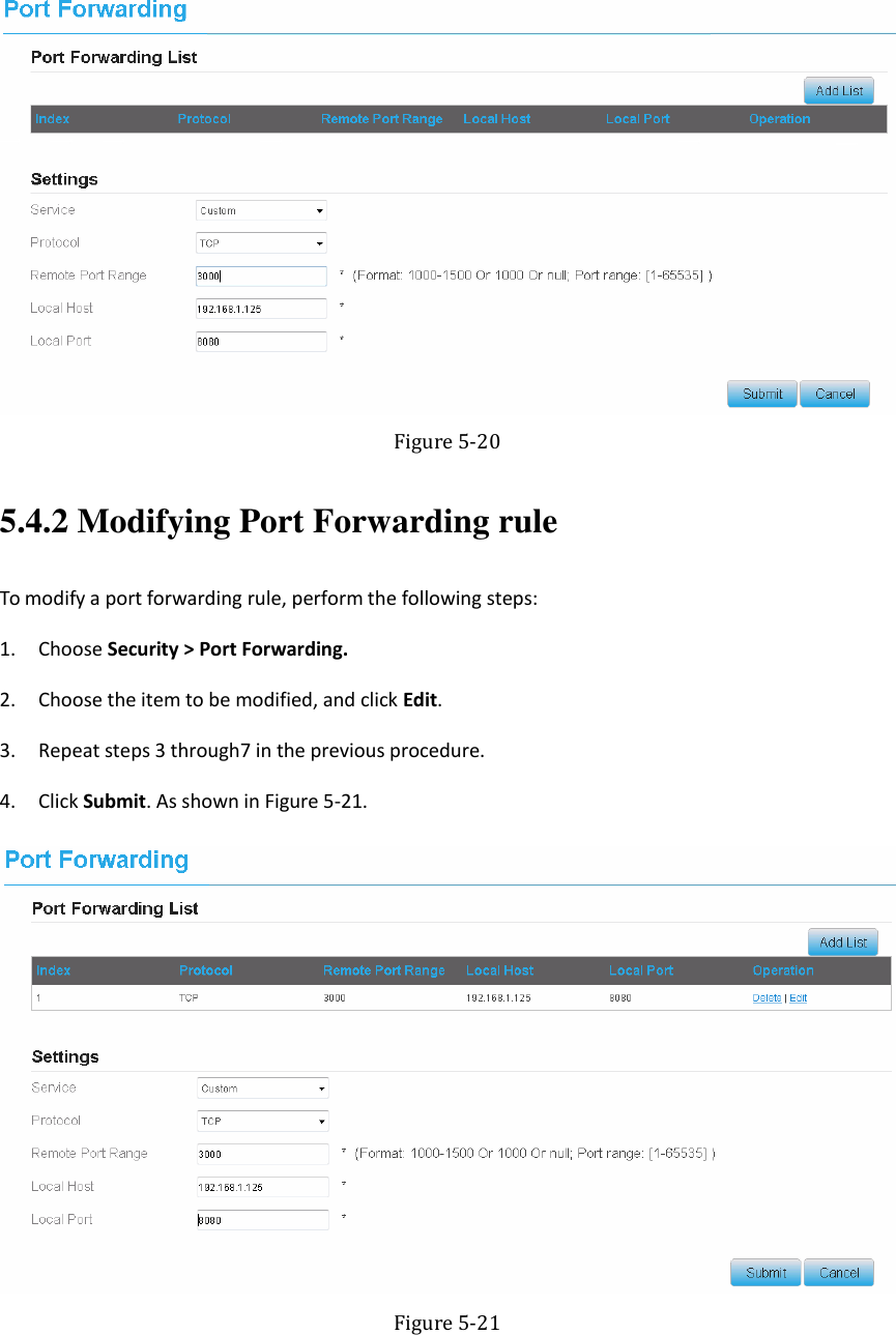
ZTE Corporation Wi-Fi Router
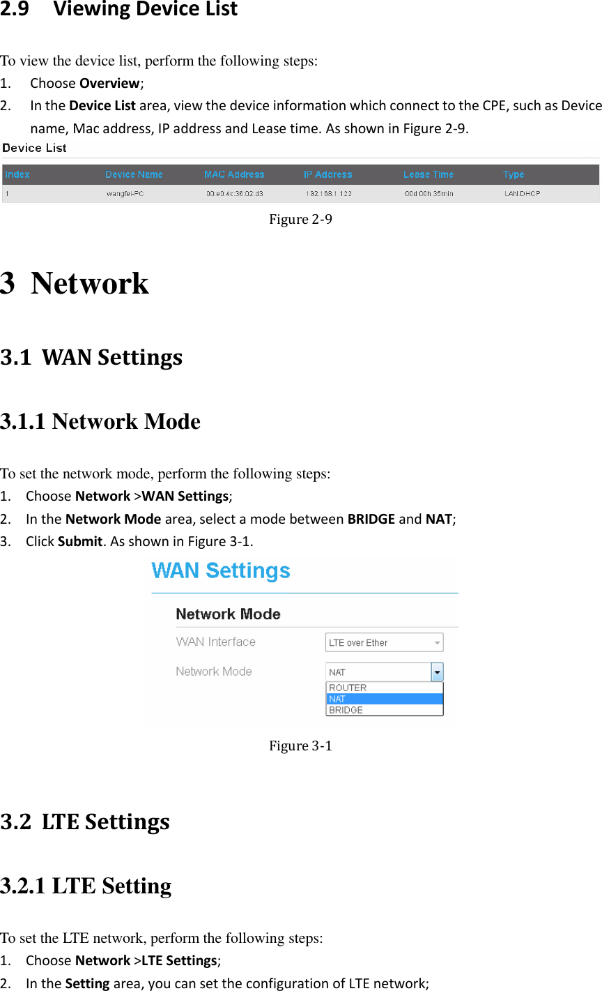
UserManual.wiki
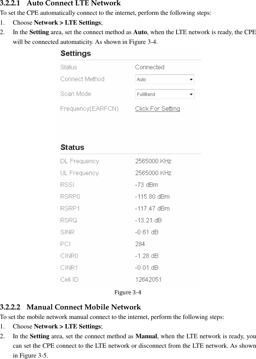
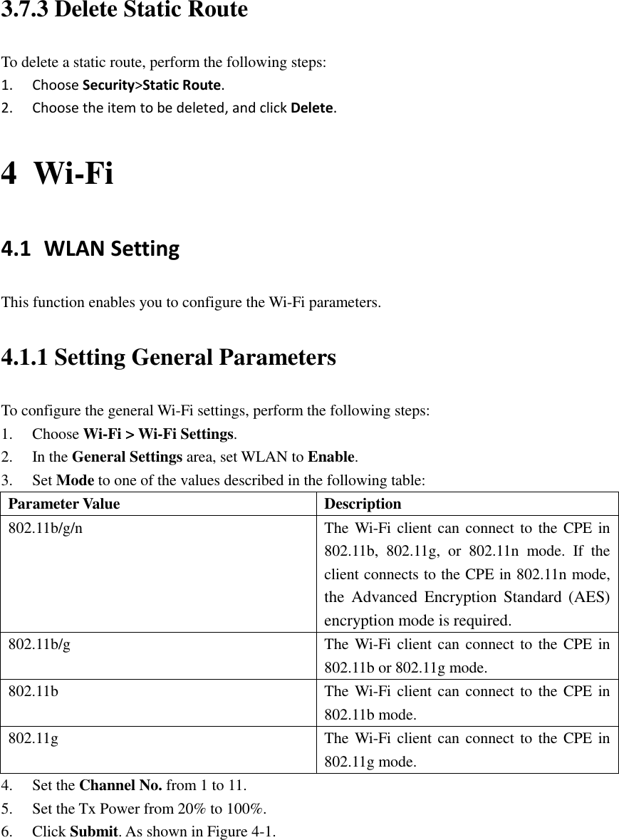
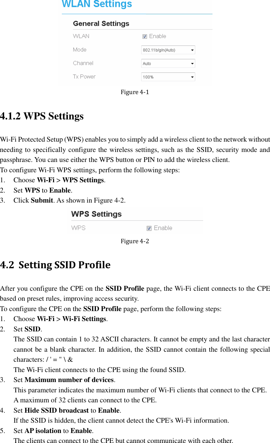
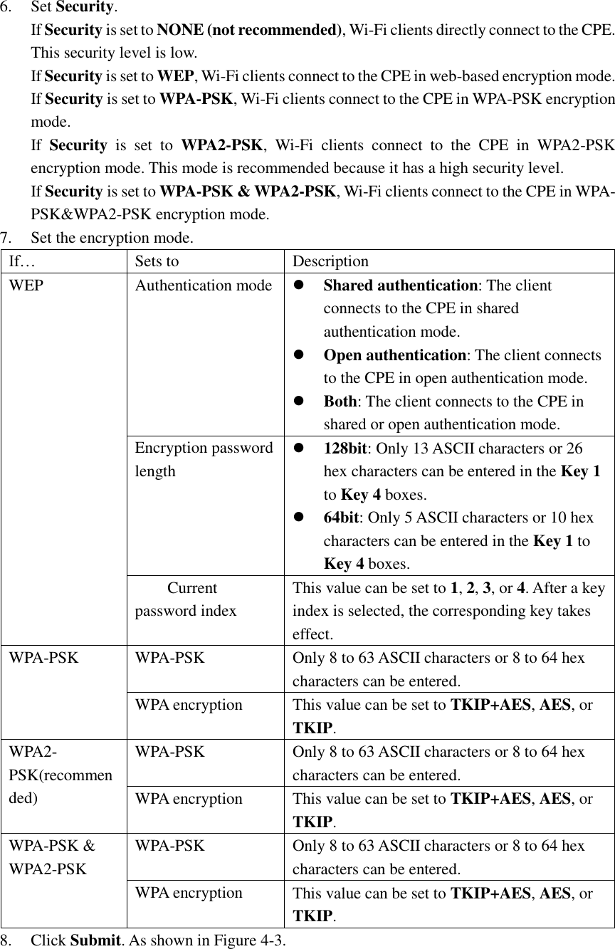
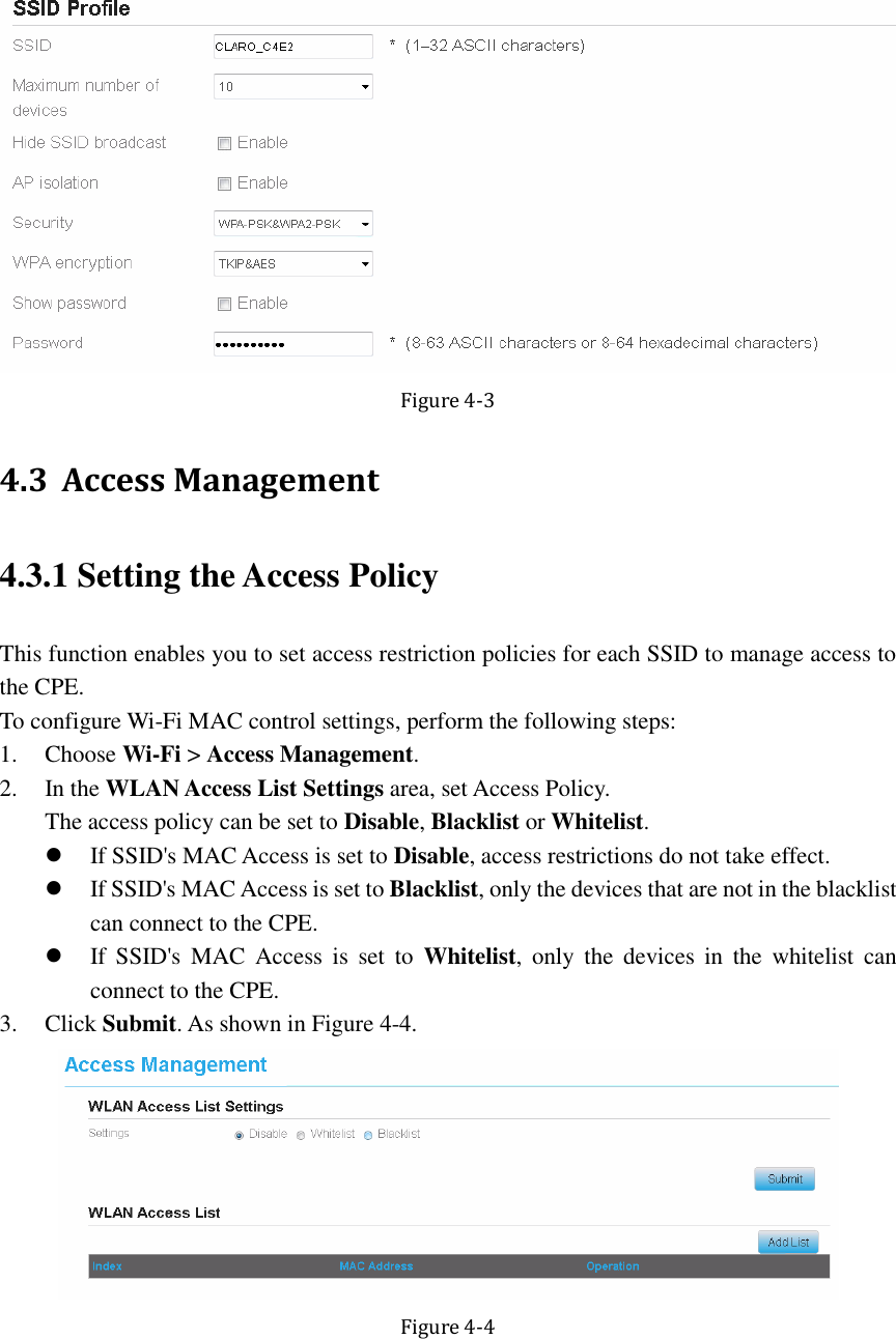
>
ZTE
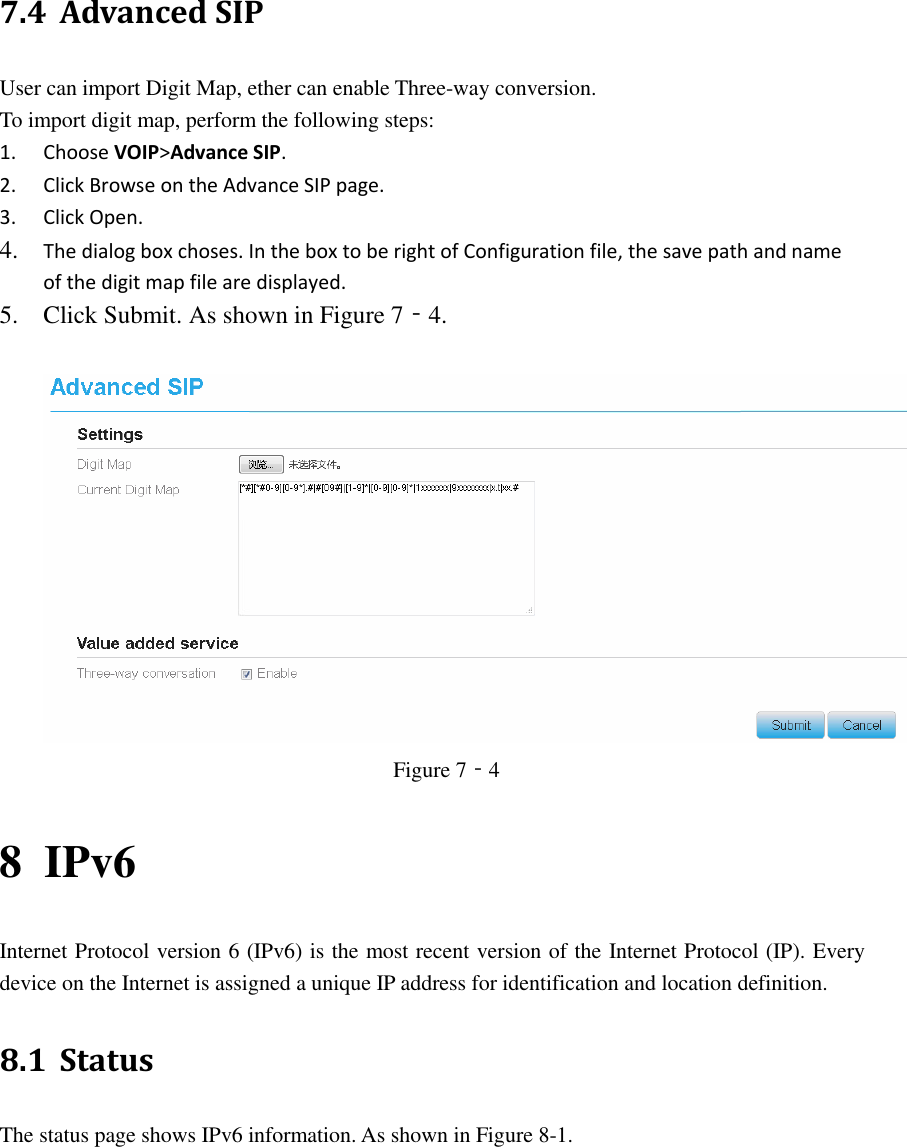
>
WF820R User Manual
User manual
Navigation menu
Upload a User Manual
Namespaces
Wiki Guide
HTML
PDF
Info
Views
User Manual
Discussion / Help
Navigation