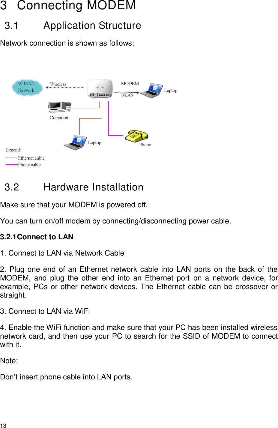
ZTE ZTEIX256 WIMAX Modem User Manual
ZTE Corporation WIMAX Modem Users Manual
UserManual.wiki
>
ZTE
>
ZTEIX256 User Manual
Users Manual
Navigation menu
Upload a User Manual
Namespaces
Wiki Guide
HTML
PDF
Info
Views
User Manual
Discussion / Help
Navigation
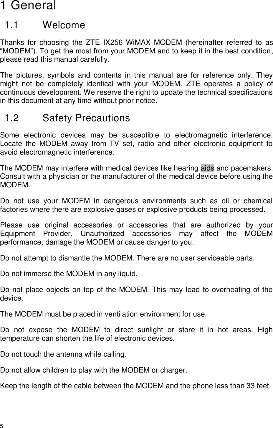

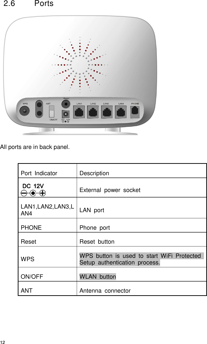
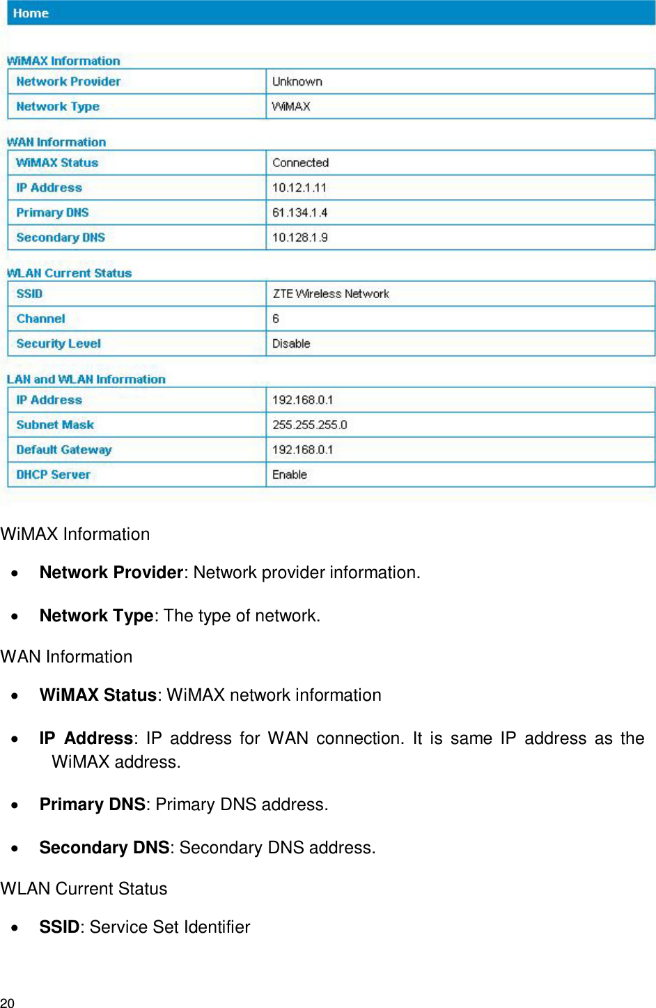
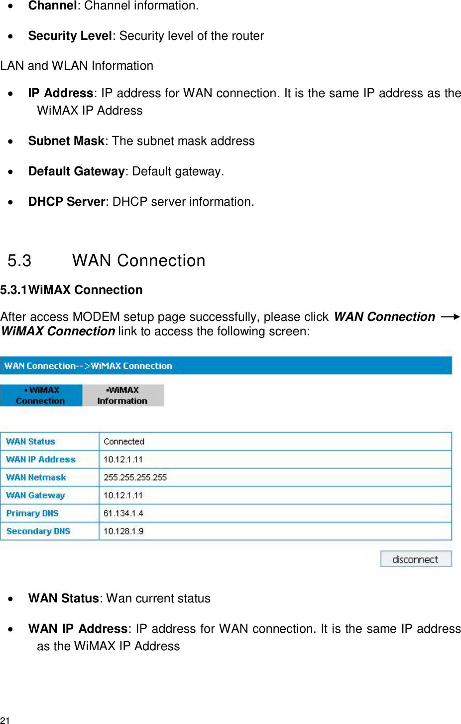
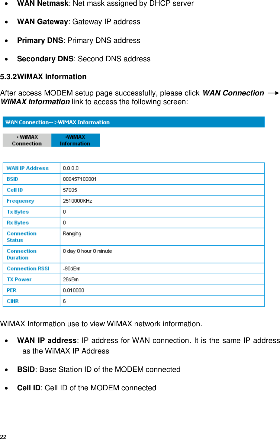
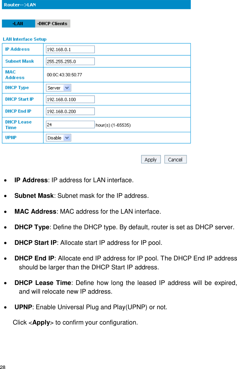
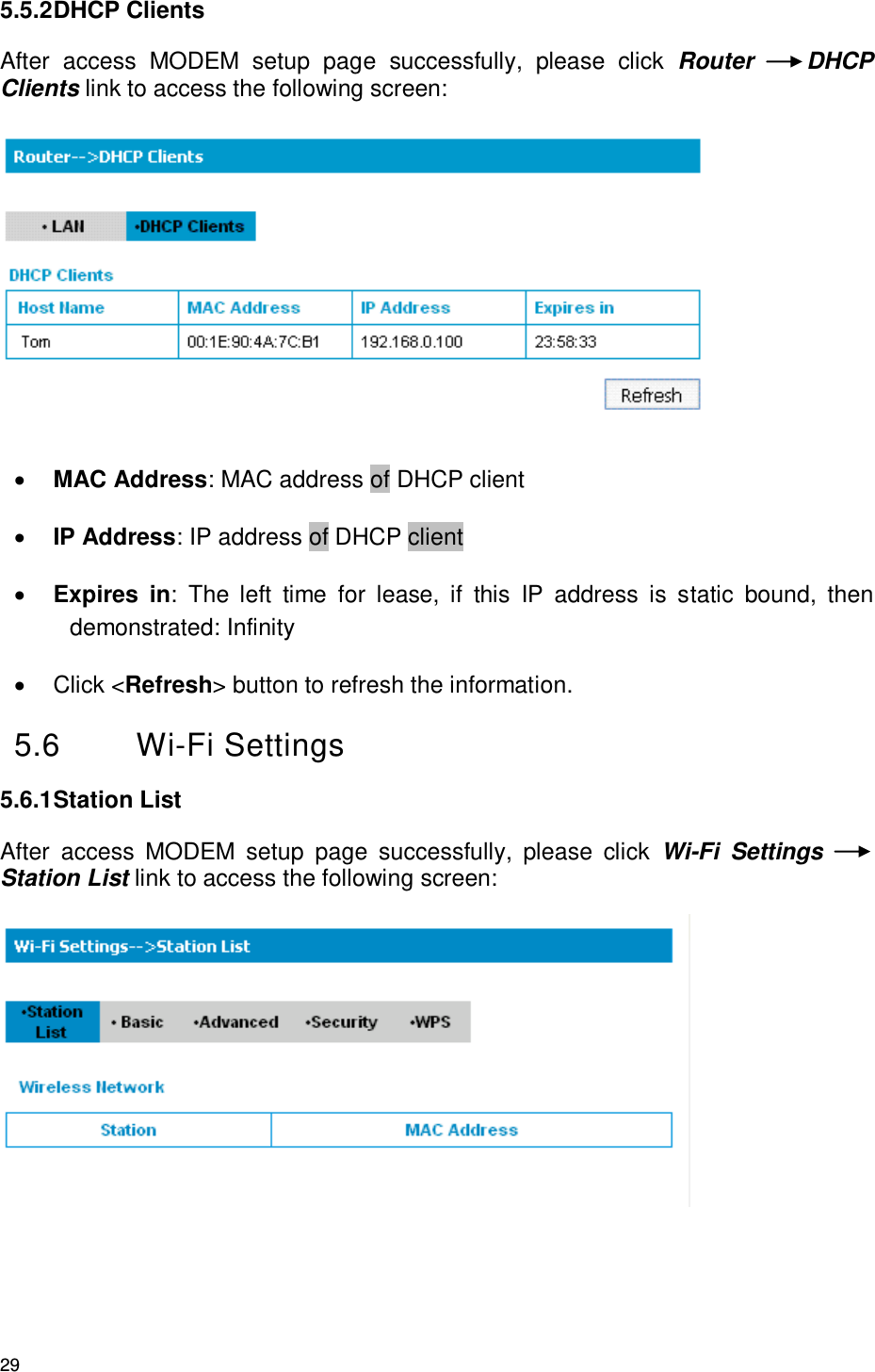
![11 2.4 Working Condition Working Condition for Host Working temperature: 0℃ ~ +55℃ [32 ℉ ~ 131 ℉] Working humidity: 10% ~ 85% Storage temperature: -40℃ ~ +70℃ [-40 ℉ ~ 158 ℉] Storage humidity: 5% ~ 95% 2.5 Technical Parameters Mode of Access WiMAX (Worldwide Interoperability for Microwave Access) WiMAX Protocol 802.16e(IEEE 802.16-2005) WiFi protocol IEEE 802.11b/g/n WiMAX Frequency Range 2496MHz~2690MHz WiFi Frequency Range 2400MHz~2483.5MHz Dimensions (W×H×D) 201.7mm*155.7mm*54.8mm Weight About 511 g Please refer to the real objects for the related parameters about the charger.](https://usermanual.wiki/ZTE/ZTEIX256/User-Guide-1368209-Page-11.png)