ZTE ZTEMF212 HSUPA mini PCI-E Modem User Manual ZTE MF628 HSDPA USB Modem
ZTE Corporation HSUPA mini PCI-E Modem ZTE MF628 HSDPA USB Modem
ZTE >
User Manual(english)_rev1
1
ZTE MODEM Mobile Connection
User Manual
2
1 Software Installation
1.1 Installation Instruction
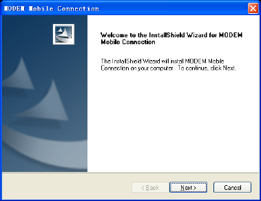
The following installation interface will show how to install the
software.
Recommend you to exit other programs, and then click
“Next”.
3
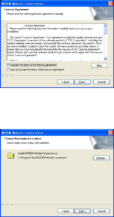
Read the agreement carefully. If you agree, choose “I
accept the terms of the license agreement”, and then click
“Next”.
Select the folder that you want to install the software by
4
pressing “Change”, and then click “Next”.
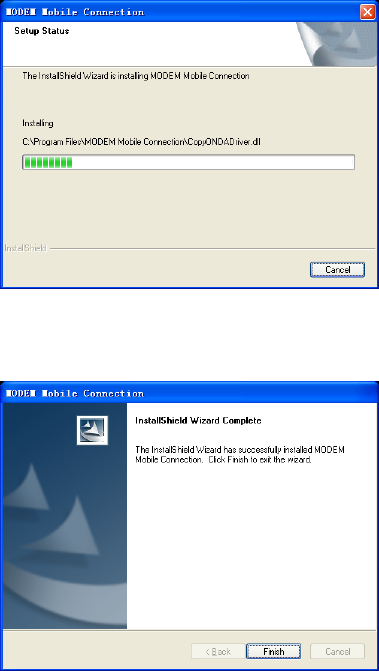
The system show the installation progress, wait a minute
and the following screen will show up:
Click “Finish” to complete the installation.
5
Note:If you have problems with installation after the upper
operation, please contact the service provider.
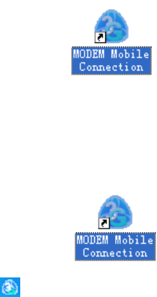
After the installation, select the “Start → Programs” and there
will be a “MODEM Mobile Connection” program group,which
includes “MODEM Mobile Connection” and “MODEM
Uninstall”. There will be a Shortcut icon like below on the
desktop.
1.2 Run the Application Software
After the modem is correctly connected, click the “Start →
Programs → MODEM Mobile Connection →MODEM Mobile
Connection” menu on the laptop or desktop PC to run the
application software.
Or double click the shortcut icon, to run the application software.
After modem initialized, main interface appears. When the
standby icon appears in the taskbar, the modem can work
properly.
1.3 Software Uninstall
Close the application program before the software
uninstalls.
Click “Start→ Programs→ MODEM Mobile Connection
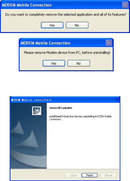
6
→ MODEM Uninstall” menu on the laptop or desktop PC.
Click “Yes” according to the indication, then the system
begins to uninstall programs.
Click “Finish” to complete the application software
uninstall.
7
2 Functions & Operation
2.1 Interface introduction
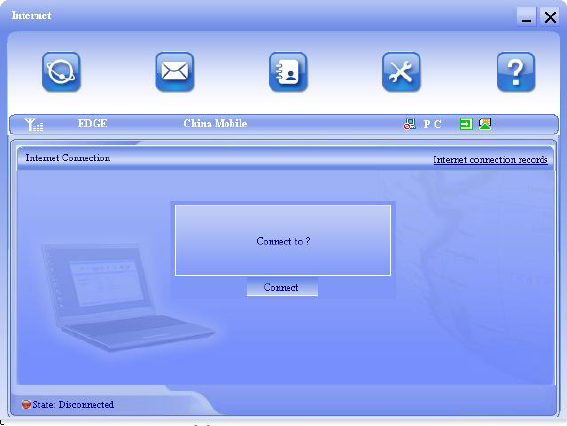
2.1.1 Main Interface
The starting screen of the Device software is shown as the
following:
The whole interface is divided into three parts. Related functions
can be executed by operation in the related areas.
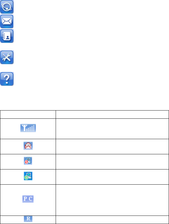
1. Function button area:
There will show various function button icons. Select different
function button and it will carry out corresponding operation.
8
Internet: Connect to the Internet.
Short Message (SMS): Send SMS or read SMS.
PhoneBook: Save and view the different information of
the contacts.
Settings: Set normal relative information for the
modem.
Help: Show the help information.
2. System information area:
Show the system status and different kinds of tips.
Icon
Explanations
The icon indicates the network signal
intensity. There are 6 stages from none
to the strongest.
The icon indicates there are new SMS at
present.
The icon indicates the current status of
Internet connection is not connected.
The icon indicates the current status of
Internet connection is already connected.
Letter “P” means supporting
packet-switch (P)service, letter “C”
means supporting circuit-switch (C)
service.
SIM/USIM card is in status of roaming.
9
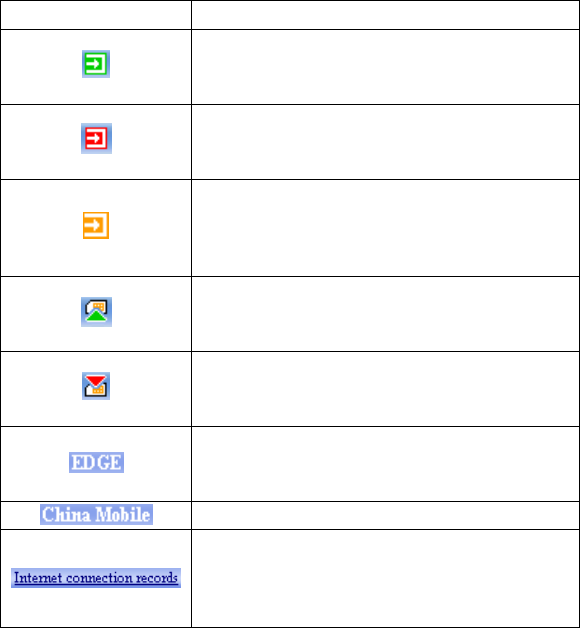
Icon
Explanations
The icon indicates insert status of the
modem. Green means it has been
inserted into the computer.
The icon indicates insert status of the
modem. Red means it has not been
inserted into the computer.
The icon indicates insert status of the
modem. Yellow means it has been
inserted into the computer but in offline
status.
The icon indicates insert status of the
SIM/USIM card to the modem. Green
means the card has been inserted.
The icon indicates insert status of the
SIM/USIM card to the modem. Red
means it has not been inserted.
The icon indicates the current network
type, i.e. EDGE or GPRS,
HSDPA/HSUPA service.
Name of the current service provider.
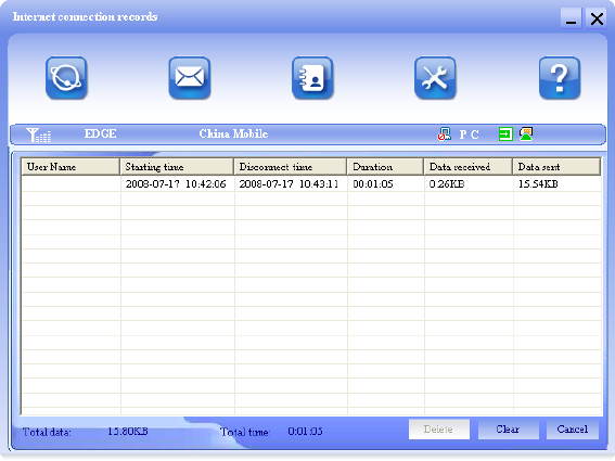
View related information for your internet
operation, such as, user name, start time,
disconnect time, duration, data received
and data sent.
3. User Area:
Show the man-computer interaction information under various
conditions.

10
2.1.2 Description of Mini Icons
When click the mini button, the software will minimize as an icon
on the system taskbar. If connected to the Internet, the
minimized software won’t influence the download of data or
receiving SMS. When the application window is minimized, the
system icons will display on the taskbar. Double click the icon to
resize the display.
1. Taskbar Icons Description:
The Device has been inserted into the computer.
The Device is not inserted into the computer.
The Device is offline.
UIM/SIM card is not inserted.
No network signal.
There is a new message.
The Device is ready to connect to Internet.
The Internet is already connected.
2. The uses of Tray Icons:
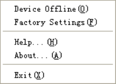
Right Click the tray icons, the following menu will appear:
11
Device Offline/ Device Online: Pause/reusing the working of
the modem. If connected Internet, you need disconnect the
Internet first, and then select the Device Offline.
Factory Settings: Restore all the settings to the original values
in the Device. This operation just affects the settings in the
Device and do not change any software settings in the laptop or
desktop PC.
Help: Enter the Device software help.
About: View the information of the application software and
hardware versions.
Exit: Close the software and stop the modem from working.
2.2 Connecting Internet
You can browse web pages after you have accessed to Internet
with the help of modem, you can also receive SMS when surfing
in the Internet.
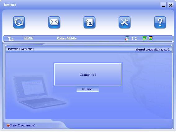
1. Connect to the Internet:
Click the Internet icon. Then the system will ask you “Connect
to ?”. Select “Connect”.
12
When connected, there is a status bar in the bottom of the user
area which shows “State: connected to …”, and the user area
will show data amount, connected time and so on. Then you can
access Internet and receive email etc through network.
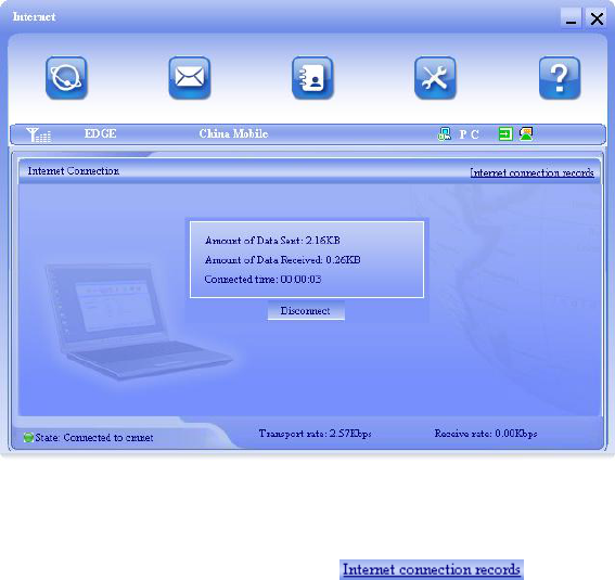
13
You can click “Disconnect” to stop the connection when the
“Connect” 'button becomes “Disconnect” button,
2. Internet connection records:
Click “Internet connection records” to check
the log of Internet connection history.
14
2.3 SMS
Note: To ensure that the Short Message can be used properly,
at first, you should setup the correct Short Message center
number. Refer to section “3.5.4 Message Settings”.
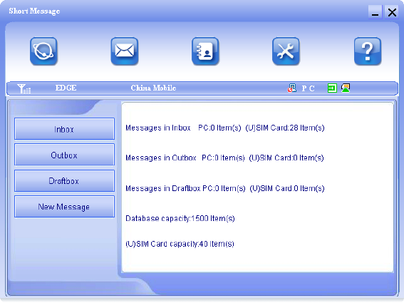
Click the “Short Message” icon to switch to the SMS interface
and it will show the number of messages in the inbox, outbox
and draftbox. The user can click icons of “InBox”, “OutBox”,
“DraftBox” and “New Message” to enter relative interface.
15
InBox: Save the received messages.
OutBox: Save the successfully sent messages.
DraftBox: Save the editing SMS which haven’t been sent. The
drafts can only be saved in computer, not USIM/SIM.
New Message: Write a new message.
For example: “Message in InBox PC : 2 Item(s) (U)SIM Card: 1
Item(s)” means: The PC side has 2 short messages and there is
1 short message in the Inbox of the SIM card , “(U)SIM Card
capability:40Item(s)” means the SIM card can hold 40 short
messages.Different SIM/USIM cards will have different
capacities. The modem will show the capacity automatically in
usage, like the above “40”. For more information, please consult
your supplier.
16
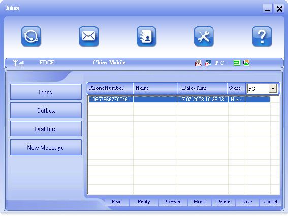
2.3.1 Read Short Message
Click the “Inbox” button on the main interface or click new
message icon on the system taskbar to read the SMS saved in
the box.
You can use the buttons under the menu to execute reading,
forwarding, deleting, saving contact functions and so on.
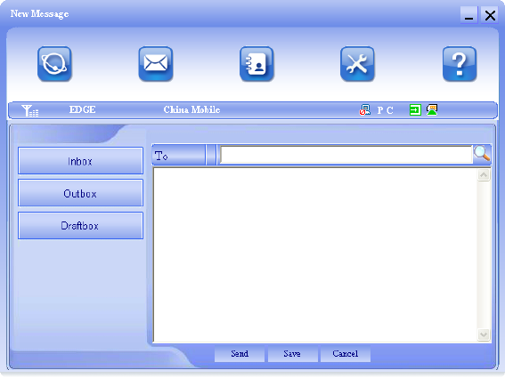
2.3.2 Create new message
Click “New Message” button to input the recipient’s number and
message content.
17
The recipient’s number can be input directly or by entering the
phonebook to select one/more/group records.
The recipient’s amount can be one or more. Please use “;” to
separate recipients.
The SMS content can include 160 individual English characters
(including English symbols). There will show total characters on
the interface.
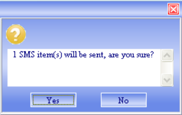
Click “Send”, the prompt screen like bellow will appear on the
interface.
18
Select “Yes”, and then the edited short messages will be sent.
After sent successfully, the SMS will be saved into outbox
automatically. If send fails, it will be saved to the draft box
automatically.
Send SMS while browse the web:
When surfing the Internet, if your network supports, you can
send short messages at the same time. Click “Short Message”
button icon, enter the short message interface to send short
messages normally.
2.3.3 Operating Guide
Enter any of the InBox/OutBox/DraftBox to execute the
following functions:

19
Read: Read all the information of short messages. (The content
of short messages, sender’s phone number, delivered date and
time)
Reply: Reply short messages to the sender (Can’t be executed
in OutBox / DraftBox).
Forward: Send the short message to other recipients (Can’t be
executed in DraftBox)..
Move: Change the saving location of short messages between
PC or USIM/SIM card (Can’t be executed in DraftBox).
Delete: Delete the selected short messages.
Save: Save sender’s number into the phonebook.
Cancel: Return to the SMS interface.
Make use of “Ctrl”or “Shift”key and click to choose several
messages to execute simultaneously.
20
New message can not be received when the USIM/SIM card is
full of short messages (Different USIM/SIM cards have different
capacities). While new message can not be saved, the system
will indicate the inbox is full and prompt user to clear the inbox at
USIM/SIM card side.
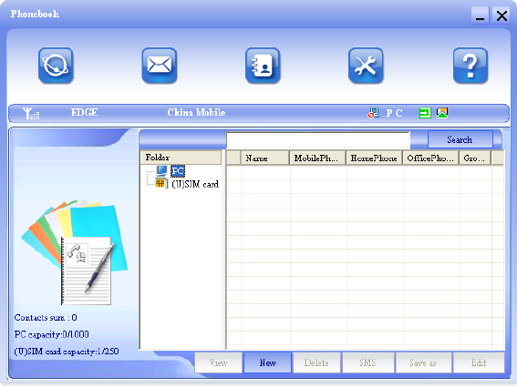
2.4 PhoneBook
Click the ”PhoneBook” icon to access to the phonebook window,
the phonebook information can be saved in the PC or SIM/USIM
card and you can choose the save position. Each record
includes contact name, mobile phone number, home phone
number, office phone number, email and the group name which
it belongs to.
21
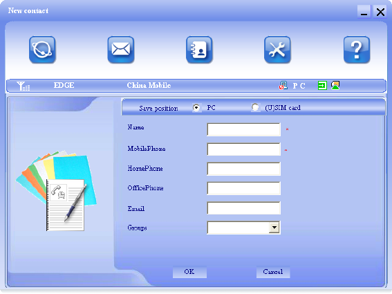
2.4.1 Creating a new contact
1) Click New → New Contact.
2) Select Save position to decide where you want to save your
contact, PC or (U)SIM card.
3) Input the name, phone number, Email address, etc. Then
click OK.
2.4.2 Modifying contacts
1) Select a contact and then double-click it or click “Edit”.
2) After the modification, click “OK”.
22
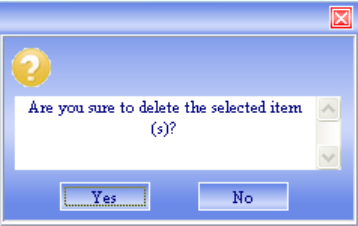
2.4.3 Deleting contacts
1) Select one or more contacts and then click “Delete”.
2) At the prompt, click “Yes”.
2.4.4 Sending SMS to a contact
1) Select one or more contacts and then click “SMS”.
2) You will access in the writing SMS window automatically, the
selected contact mobile phone numbers will be listed in the
receiver column.
3) Enter the contents of the message and then click “Send”.
4) At the prompt, click “Yes” to send the SMS.
2.4.5 Searching for a contact
1) Enter the search conditions in the search condition blank.
2) Click Search begin searching.
3) The searching results will display in the contacts window.
2.5 Settings
Click “Settings” icon to switch to the settings interface. It
includes: Connection settings, Security settings, Network
settings, Message settings, Alert settings.
23
Note: all the necessary settings have been correctly saved in
your Device. There is no need to change these default settings.
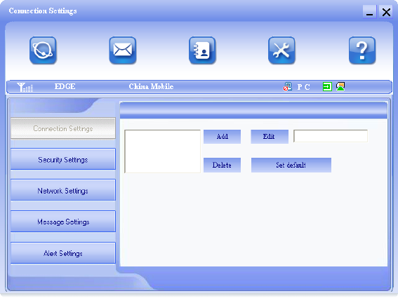
2.5.1 Connection Settings
To ensure that the modem can connect the Internet properly,
you should configure the connection information first.
1. Button description
Add: Add new configuration file.
Delete: Delete the selected configuration file.
Edit: Edit the selected configuration file.
Set default: Select one configuration file from the list, and set it
as the current using files.
24
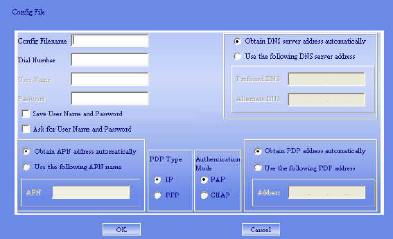
2. Config File
Click “Add” to add new connection information to the system.
The “Config File” interface will appear:
The configuration information includes: Config Filename, Dial
Number, User name, Password, APN, DNS, and PDP address.
If network supports “Obtain server address automatically”, the
modem can obtain the assigned IP information automatically. If
network does not support it, you should input the proper address
manually. Please consult the network supplier of SIM/USIM card
for all above information. The configuration information may be
various according to the different network suppliers and network
types.
25
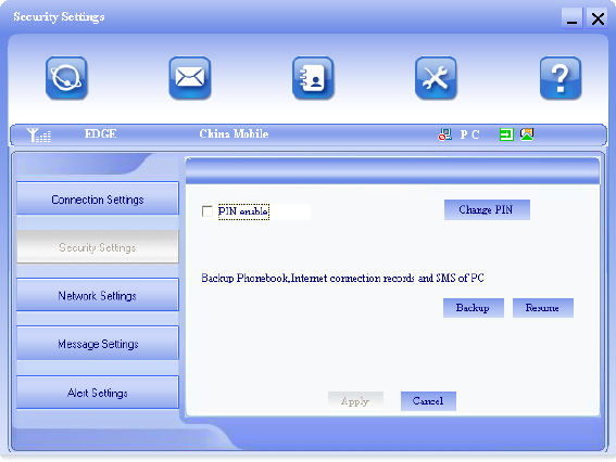
2.5.2 Security Settings
1. Enable the PIN Code
When “PIN enable” item is selected, please enter PIN code to
use the modem and you can click “Change PIN” to modify the
number.
2. Backup Phonebook, Internet connection records
and SMS of PC
Click “Backup” to backup the Phonebook, SMS and Internet
connection records in PC.
Click “Resume” to restore the backup data.
26
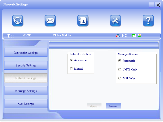
2.5.3 Network Settings
1. Select Network
Automatic: The system selects the network automatically by
the user’s selected rules and the network status.
Manual: The network is selected by users themselves.
2. Network Mode Select
Automatic: The system will search valid network automatically.
UMTS Only: The system will only search UMTS network.
GSM Only: The system will only search GSM network.
27
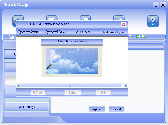
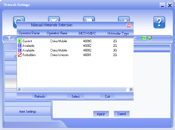
3. Manual Select
When the “Manual” is selected, click the “Apply” button, pop-up
the following window:
Wait a minute, the supplier list will show in the window and the
suppliers with the blue or green icon can be selected. Select a
proper network to connect.
28
Select the network that the supplier is utilized to serve your
USIM/SIM and press “Select” to attach the network.
29
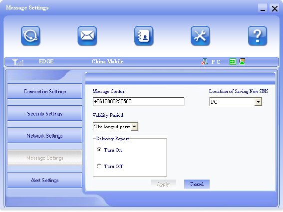
2.5.4 Message Settings
Message Center: Set the corresponding SMS center number.
You must input the correct SMS center number to use the SMS
properly and the number will be provided by the network
supplier. Please enter the country code before the number.
Validity period: Set the time limit for saving SMS in the network
side. (This function needs network supports.)In option :12
hours/A day/A week/The longest period. The default setting is
the longest period permitted by the network.
Location of Saving New SMS: Select “Default” to save in
location set by network. Select “(U)SIM Card” to save in
USIM/SIM card; select “PC” to save in laptop or desktop PC.
Delivery Report: Set as “Turn On” or “Turn Off”. When it is set
as “Turn On”, the network will inform you of the status for the
30
sent messages.
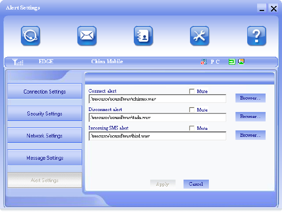
2.5.5 Alert settings
You can set “Connect alert, Disconnect alert and Incoming SMS
alert” by yourself. These alerts will sound on the PC side. The
audio file supports MP3、WAV、WMA and MIDI format. If you
select “Mute”, you cannot hear corresponding alert.
2.6 Help
Click “Help” icon, and switch to the help interface. Under the
help topic, you can get the Device information about function
introductions, installation and usage guide, etc.
31
FCC Compliance
This device complies with part 15 of the FCC Rules. Operation is
subject to the following two conditions: (1) This device may not
cause harmful interference, and (2) this device must accept any
interference received, including interference that may cause
undesired operation.
Caution: Changes or modifications not expressly approved by
the manufacturer could void the user’s authority to operate the
equipment.
NOTE: This equipment has been tested and found to comply
with the limits for a Class B digital device, pursuant to part 15 of
the FCC Rules. These limits are designed to provide reasonable
protection against harmful interference in a residential
installation. This equipment generates, uses and can radiate
radio frequency energy and, if not installed and used in
accordance with the instructions, may cause harmful
interference to radio communications. However, there is no
guarantee that interference will not occur in a particular
installation. If this equipment does cause harmful interference to
radio or television reception, which can be determined by turning
the equipment off and on, the user is encouraged to try to
correct the interference by one or more of the following
measures:
—Reorient or relocate the receiving antenna.
—Increase the separation between the equipment and receiver.
—Connect the equipment into an outlet on a circuit different from
that to which the receiver is connected.
—Consult the dealer or an experienced radio/ TV technician for
help.
32
2.8 RF Exposure
Your device contains a transmitter and a receiver. When it is ON,
it receives and transmits RF energy. When you communicate
with your device, the system handling your connection controls
the power level at which your device transmits.
Important safety information regarding radiofrequency radiation
(RF) exposure. To ensure compliance with RF exposure
guidelines the device must be used with a separation from the
body. Failure to observe these instructions could result in your
RF exposure exceeding the relevant guideline limits.
The maxim permissible exposure is defined in 47 CFR 1.1310
with 1mW/cm*cm. The transmitter is using external antenna that
operate at 20cm or more from nearby persons. The maxim
power density is 0.157mW/cm*cm.