ZTE ZTEMF612 HSUPA Wireless Access terminal User Manual MF612 rev2
ZTE Corporation HSUPA Wireless Access terminal MF612 rev2
ZTE >
user manual MF612 rev2
1
ZTE MF612
3G Wireless Router
User Manual
2
WELCOME
Thank you for choosing the ZTE MF612 3G Wireless Router
(hereinafter referred to as “unit” or "router"). To get the most from your
router and to keep it in the best condition please read this manual
carefully.
The pictures, symbols and contents in this manual are for reference
only. They might not be completely identical with your router. ZTE
operates a policy of continuous development. We reserve the right to
update the technical specifications in this document at any time without
prior notice.
3
Glossary
AC: Alternating Current
APN: Access Point Name
DC: Direct Current
DHCP: Dynamic Host Control Protocol
DNS: Domain Name System (or Service or Server)
DoS: Denial of Service
EDGE: Enhanced Data GSM Evolution
ESSID: Expanded Service Set Identifier
Ethernet: A frame-based computer networking technology for
local area networks (LANs)
GSM: Global System for Mobile Communications
GPRS: General Packet Radio Service
HSDPA: High Speed Downlink Packet Access
HSUPA: High Speed Uplink Packet Access
IP: Internet Protocol
LAN: Local Area Network
LED: Light - emitting Diode
MHz: Megahertz
MTU: Maximum Transmission Unit
PDP: Packet Data Protocol
PIN: Personal Identification Number
PPP: Point to Point Protocol
PSTN: Public Switched Telephony Network
PUK: PIN Unlocking Key
RSSI: Radio Signal Strength Indicator
RF: Radio Frequency
SIP: Session Initiated Protocol
UPnP: Universal Plug and Play
(U)SIM: Subscriber Identification Module
VOIP: Voice over Internet Protocol
WCDMA: Wideband CDMA (Code-Division Multiple Access)
WEP: Wired Equivalent Privacy
WLAN: Wireless LAN
WPA-PSK: Wi-Fi Protected Access–PreShared Key
4
Content
1 General Information ................................................................ 6
1.1 Safety Precautions .......................................................................... 6
1.2 Declaration ....................................................................................... 6
1.3 Cleaning and Maintaining ............................................................... 8
1.4 Limited Warranty .............................................................................. 8
1.5 Limitation of Liability ....................................................................... 9
1.6 Emergency Call ................................................................................ 9
2 Getting started ...................................................................... 10
2.1 Parts Supplied ................................................................................ 10
2.2 Router Appearance ........................................................................ 10
2.2.1 LED Indicator ......................................................................... 10
2.2.2 Power Switch ......................................................................... 12
2.3 Interface and Installation ............................................................... 12
2.3.1 Interface Description ............................................................ 12
2.3.2 Installation ............................................................................. 13
2.4 Power Supply ................................................................................. 14
2.5 About the (U)SIM Card ................................................................... 15
3 Voice ..................................................................................... 16
3.1 Making a Call .................................................................................. 16
3.1.1 Making a Trunk Call .............................................................. 16
3.1.2 Making an International Call ................................................ 16
5
3.2 Answering a Call ............................................................................ 16
4 Internet Access ..................................................................... 18
4.1 Preparation ..................................................................................... 18
4.2 Settings .......................................................................................... 18
4.2.1 Login ...................................................................................... 19
4.2.2 WAN Connection ................................................................... 23
4.2.3 3G Settings ............................................................................ 24
4.2.4 Router .................................................................................... 26
4.2.5 Wi-Fi Setting .......................................................................... 27
4.2.6 Firewall ................................................................................... 37
4.2.7 Advanced ............................................................................... 41
4.3 Logout ............................................................................................ 44
4.4 Disconnecting from the Internet ................................................... 45
5 Troubleshooting .................................................................... 46
6 Technical Parameters ........................................................... 48
6
1 General Information
1.1 Safety Precautions
Some electronic devices may be susceptible to electromagnetic
interference. Locate the router away from TV set, radio and other
electronic equipment to avoid electromagnetic interference.
The router may interfere with medical devices like hearing aides
and pacemakers. Consult a physician or the manufacturer of the
medical device before using the router.
Please keep yourself at least 20 centimeters away from router.
Do not use your router in dangerous environments such as oil
terminals or chemical factories where there are explosive gases
or explosive products being processed.
Please use original accessories or accessories that are
authorized by ZTE. Unauthorized accessories may affect the
router performance, damage the router or cause danger to you.
Do not attempt to dismantle the router. There are no user
serviceable parts.
Do not allow the router or accessories to come into contact with
liquid or moisture at any time. Do not immerse the router in any
liquid.
Do not place objects on top of the router. This may lead to
overheating of the device.
The device must be placed in ventilation environment for use.
Do not expose the router to direct sunlight or store it in hot areas.
High temperature can shorten the life of electronic devices.
Do not allow children to play with the router or charger.
Keep the length of the cable between the router and the phone
less than 10 meters.
The router is for indoor use only. Do not use the router outside.
Do not connect telephone extensions which run outside of the
building. These can result in lightning damage to your unit.
1.2 Declaration
We, ZTE Corporation, declared that:
The user is cautioned that changes or modifications not expressly
approved by the manufacturer could void the user's authority to
operate the equipment.
7
This device complies with part 15 of the FCC Rules. Operation is
subject to the condition that this device does not cause harmful
interference.
Note: This equipment has been tested and found to comply with the
limits for a Class B digital device, pursuant to part 15 of the FCC Rules.
These limits are designed to provide reasonable protection against
harmful interference in a residential installation.
This equipment generates, uses and can radiate radio
frequency energy and, if not installed and used in accordance
with the instructions, may cause harmful interference to radio
communications. However, there is no guarantee that
interference will not occur in a particular installation. If this
equipment does cause harmful interference to radio or television
reception, which can be determined by turning the equipment off
and on, the user is encouraged to try to correct the interference
by one or more of the following measures:
—Reorient or relocate the receiving antenna.
—Increase the separation between the equipment and
receiver.
—Connect the equipment into an outlet on a circuit different
from that to which the receiver is connected.
—Consult the dealer or an experienced radio/ TV technician
for help.
Changes or modifications not expressly approved by the party
responsible for compliance could void the user‘s authority to operate
the equipment.
8
1.3 Cleaning and Maintaining
Use an antistatic cloth to clean the router. Do not use chemical or
abrasive cleanser as these could damage the plastic case. Turn
off your router before you clean it.
Use the router within the temperature range of -10°C ~ +55°C, and
the storage temperature range is -20°C ~ +65°C. The humidity
range is 5%~95%.
Do not use your router during a thunderstorm. Remove the mains
power pack from the wall socket.
Do not take out your (U)SIM card unnecessarily. The (U)SIM card
may be easily lost or it can be damaged by static electricity.
1.4 Limited Warranty
This warranty does not apply to defects or errors in the Product
caused by:
(a) Reasonable Router Appearance Disfiguration.
(b) End User’s failure to follow ZTE’s installation, operation or
maintenance instructions or procedures.
(c) End User’s mishandling, misuse, negligence, or improper
installation, disassemble, storage, servicing or operation of
the Product.
(d) Modifications or repairs not made by ZTE or a ZTE-certified
individual.
(e) Power failures, surges, fire, flood, accident, actions of third
parties or other events outside ZTE’s reasonable control.
(f) Usage of products of third Parties, or usage in conjunction with
third party products provided that such defects is due to the
combined usage.
(g) Any other cause beyond the range of normal usage for
Products. End User shall have no right to reject, return, or
receive a refund for any Product from ZTE under the above-
mentioned situations.
This warranty is end user’s sole remedy and ZTE’s sole liability
for defective or nonconforming items, and is in lieu of all other
warranties, expressed, implied or statutory, including but not
limited to the implied warranties of merchantability and fitness for
a particular purpose, unless otherwise required under the
mandatory provisions of the law.
9
1.5 Limitation of Liability
ZTE shall not be liable for any loss of profits or indirect, special,
incidental or consequential damages resulting from or arising out of or
in connection with using of this product, whether or not ZTE had been
advised, knew or should have known of the possibility of such
damages, including, but not limited to lost profits, interruption of
business, cost of capital, cost of substitute facilities or product, or any
downtime cost.
1.6 Emergency Call
Do not rely on the 3G Wireless Router to provide emergency call in all
situations.
Your 3G Wireless Router only supports emergency dialing when there
is power and connection to the mobile network. If the power fails, the
router can not work. If you have no network coverage you will not be
able to make emergency calls. The 3G Wireless Router does not
include a lifeline facility (wired access to the PSTN).
10
2 Getting started
The router operates on the HSUPA/HSDPA/UMTS network and
GSM/GPRS/ EDGE network and supports voice and data service.
2.1 Parts Supplied
Parts Quantity
3G Wireless Router 1
External power adapter 1
User manual 1
Certificate of quality 1
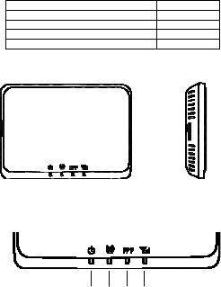
2.2 Router Appearance
2.2.1 LED Indicator
LED Indicators
1 2 3 4
Top View Left View

11
Indicator State Description
1. PWR
ON External power supply works
normally.
OFF External power supply is
disconnected or power off.
2. Wi-Fi
ON Wi-Fi works normally.
Blinking Data transmission.
OFF Wi-Fi works abnormally.
3. PPP
ON Internet connected.
Blinking The router attempts to connect
Internet.
OFF Internet disconnected and not
attempt to connect.
4. RSSI
ON
RF signal is normal. Different
color indicates different
network.
Red: GSM/GPRS/EDGE.
Green: HSDPA/HSUPA/UMTS.
Blinking RF signal is poor.
OFF RF signal is not available.
Note: The indicators (including PPP and RSSI ) are all blinking in
green when:
The (U)SIM card has not been installed.
The PIN code or PUK code is required.
The router can not work normally.
12
2.2.2 Power Switch
Turn the router On or Off by pressing the power switch at the rear of
the router.
Power Switch
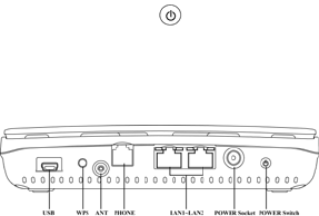
2.3 Interface and Installation
2.3.1 Interface Description
Rear View of Router
(1) USB: Test and diagnostic interface for factory use only.
(2) WPS:WPS button is used to start Wi-Fi Protected Setup
authentication process.
(3) ANT: External antenna connector. If external antenna is connected,
the internal antenna is of no effect.
(4) PHONE: Standard RJ11 connector for Telephone.
(5) LAN 1~ LAN 2: Ethernet connections to computer.
(6) POWER Socket: Connection to the external power supply.
(7) POWER Switch: Turn the router ON or OFF.

13
2.3.2 Installation
1. Insert the (U)SIM card into the (U)SIM card holder from the side of
the router.
a) Pull the plastic holder out.
b) Insert the (U)SIM card with the metal contact area facing upwards
into the holder.
c) Insert the plastic holder into the router. You can hear a click when
the (U)SIM card locks in place.

14
Warning: Please power off the router and remove the external power
adapter before removing or inserting the (U)SIM card, if not, the router
or (U)SIM card may be damaged.
2. Connect the telephone to the PHONE interface using phone
cable(RJ11).
3. Connect your computer to the LAN interface using the Ethernet
cable (RJ45).
Note: The router will adapt the Ethernet cable style (crossover or
straight) automatically.
4. Connect the external power adaptor to a standard power outlet.
Insert the plug into the socket at the rear of the router.
5. Turn the power switch on to get started. Make sure that the
phone is on hook before power on.
Note: Do not put anything on the top of router. Do not lay routers to
overlap each other when using.
6. Wait 1~2 minutes after turning the router on before you use the
service. The RSSI & PWR indicator should be lit on.
Note: When the router is turned off, an incoming caller will hear the
prompt like “The number you have dialed is currently unavailable.’’
If the RSSI (Radio Signal Strength Indicator) LED is blinking constantly
then try moving the router to another location. The router takes 1~2
minutes to initialize, attach to the network and obtain an IP address.
2.4 Power Supply
For normal operation connect the router to the external power adapter.
15
In case of power failure or when there is no available external power
supply, the router can not work.
2.5 About the (U)SIM Card
Avoid handling the (U)SIM card unnecessarily. Hold the card by the
edges to prevent static damage. Keep the (U)SIM card away from
electrical and magnetic appliances.
If you cannot get service, make sure that:
You are in an area which has network coverage.
You are using the correct (U)SIM card.
16
3 Voice
3.1 Making a Call
Before making a call, make sure:
The (U)SIM card is installed.
The telephone cable (RJ11) is connected properly.
The PWR light is on.
The RSSI light is on.
Pick up the handset.
1. Key in the telephone number.
2. You can either press # key on the telephone to send the call, or wait
4~8 seconds for the call to be connected automatically.
3.Call will be connected.
Note: If there is no RSSI indication, the RF signal is unavailable.
Change the location of the router and make sure nothing is blocking it.
3.1.1 Making a Trunk Call
If you are making a trunk call, add the area code as normal.
E.g. 03 9612 3456
3.1.2 Making an International Call
If you are making an international call, key in the international access
code followed by the country code, area code and number.
E.g. 00 11 64 12 345678
3.2 Answering a Call
When the phone rings, pick up the handset to answer it. If the
17
telephone has hands-free function you can answer the call by pressing
the Hands-free button. pressing the hands-free button again to end
the call.
18
4 Internet Access
The router does not require any drivers, and it supports all operating
systems with Ethernet LAN capability, such as Windows 2000, XP,
Vista , MAC OS X and Linux. The router supports two computers
surfing on internet using Ethernet cable at the same time, and also
supports Wireless LAN connection.
Note: All the parameter settings in this chapter are just for your
reference. Please contact your service provider for detail.
4.1 Preparation
Before using the data service, make sure:
The (U)SIM card is installed.
The Ethernet cable is connected properly.
The PWR light is on.
The RSSI light is on.
The PPP light is on.
Web browser requirement:
It is suggested that you use one of these web browsers to connect to
the internet.
IE 6.0 or above
Firefox 2.0
Netscape version 9.0
4.2 Settings
Do not change any settings unless instructed by your service provider.
To make changes to your settings you need to disconnect the router
19
from the network. After making changes reboot your router by turn off
and on again.
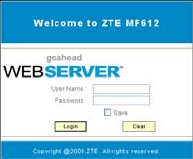
4.2.1 Login
The router can be connected by RJ45 or by Wi-Fi (the SSID is “ZTE
Wireless Network”). By either connection mode, you should set to
obtain an IP address automatically in the attribution setting of Internet
protocol(TCP/IP).
After your computer gets the IP address (like 192.168.0.101) from the
router, open a web browser and type “ http://192.168.0.1” in the
address bar, and then input the username and password.
User name: admin
Password: admin
Click Login to log in the router. Check Save to save the user name
and password.
When you successfully login, the Quick Setup procedure is shown in
the following figure:
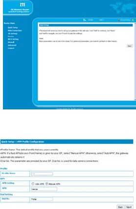
20
Quick setup guide you how to set the basic parameters for your router
in the most safe way. Click Next to go to PPP Profile Configuration in
the following figure:
.
21
Set APN for PPP profile, if you obtain a fixed APN from your service
provider , please select Manual APN, otherwise select Auto APN, and
then type the APN string. Dial No. is provided by your service provider.
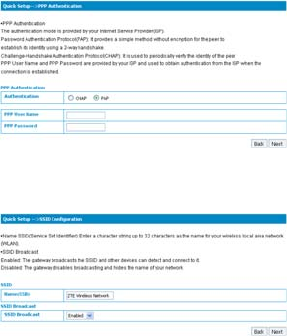
Click Next to go to the PPP Authentication in the following figure:
Choose PPP authentication mode ,CHAP or PAP , and then give PPP
user name and password to the corresponding authentication mode.
Click Next to go to SSID Configuration in the following figure:
22
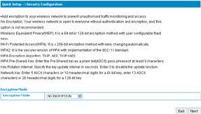
Service Set Identifier(SSID) is used to uniquely identify your WLAN. If
you enable SSID Broadcast, the gateway will broadcast the SSID, and
other device can detect and connect with it. Click Next to go to
Security Configuration in the following figure:
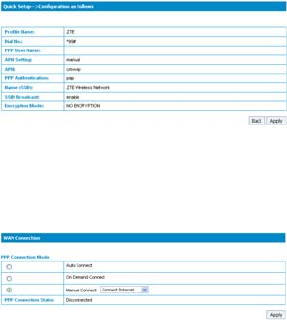
Encryption will keep your traffic from being unauthorized monitor and
access, select one encryption mode from the list, and then set key
and/or algorithm for it. Click Next to go to Configuration as Follows
in the figure below:
23
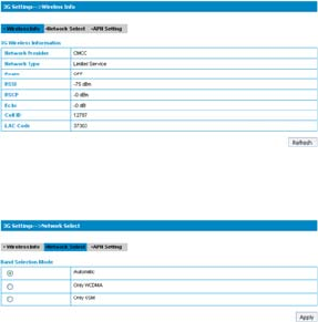
Make sure that all the parameters shown in the figure are correct, and
then click Apply.
4.2.2 WAN Connection
Click WAN Connection, you can configure how to connect to the
Internet in the following figure:
There are three connection mode:
1. Auto Connect: The router will automatically connect to WAN when
it is powered on.
2. On Demand Connect: .The connection will be established when
data transmission are required. Router will disconnect from the Internet
if there is no data traffic going through it during the Max Idle Time.
24
3. Manual Connect: Connect to Internet manually.
Click Apply to confirm your configuration, and then the PPP
connection status will be shown in the figure.
4.2.3 3G Settings
1. Wireless Info
Select 3G Settings→Wireless Info, the 3G wireless information is
shown in the following figure:
Click Refresh to update the wireless information.
2. Network Select
Select 3G Settings→Network Select, the Band Selection Mode is
shown in the following figure:
Automatic: Router searches for valid network according to the
25
wireless network.
Only WCDMA: Router searches for WCDMA network only.
Only GSM: Router searches for GSM network only.
Click Apply to confirm your configuration.
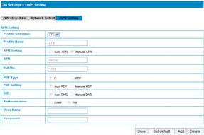
3. APN Setting
Select 3G Settings→APN Setting, the APN parameters are shown in
the following figure:
APN Setting: APN address mode. If a fixed APN is provided by
your service provider, select Manual APN. Otherwise select the
Auto APN, and the router will automatically obtain this parameter.
APN: APN string.
Dial No.: This dial number is used for data service connection.
PDP Type: Packet Data Protocol (PDP) Type IP is recommended
unless service provider instruct others.
PDP Setting: PDP address mode. If a fixed IP address is given
by your service provider, select Manual PDP. Otherwise select
the Auto PDP and the router will automatically obtain this
parameter.
DNS: If a fixed IP address is given by your service provider, then
26
choose Manual DNS. otherwise ,choose Auto DNS ,and router
will automatically obtain parameters.
Authentication: Password Authentication Protocol (PAP)
provides a simple method without encryption for the peer to
establish its identity using a 2-way handshake. Challenge-
Handshake Authentication Protocol (CHAP) is used to periodically
verify the identity of the peer using a 3-way handshake.
User Name: User name is used to obtain authentication from the
ISP when the connection is established
Password: Password is used to obtain authentication from the
ISP when the connection is established.
Click Add to define a new APN profile, and then click Save to save the
profile. Click Set default to set the parameters to their default value.
Select one profile and click Delete to delete it.
Note:You can not edit or delete the current default APN profile.
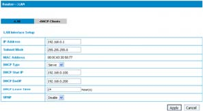
4.2.4 Router
1. LAN
Select Router→LAN, the LAN parameters are shown in the following
figure:
27
IP Address: IP address for LAN interface.
Subnet Mask: Subnet mask for the IP address.
MAC Address: MAC address for the LAN interface.
DHCP Type: Define the DHCP type. By default, router is set as
DHCP server.
DHCP Start IP: Allocate start IP address for IP pool.
DHCP End IP: Allocate end IP address for IP pool. The DHCP
End IP address should be larger that the DHCP Start IP address.
DHCP Lease Time: Define how long the leased IP address will be
expired, and will relocate new IP address.
UPNP: Enable Universal Plug and Play(UPNP) or not.
Click Apply to confirm your configuration.
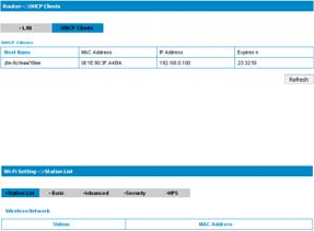
2. DHCP Clients
Select Router→DHCP Clients, the DHCP clients parameters are
shown in the following figure:
4.2.5 Wi-Fi Setting
1. Station list
Select Wi-Fi Setting→Station List, the wireless network stations are
shown in the following figure:
28
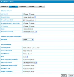
2. Basic
Select Wi-Fi Setting→Basic, the wireless network basic parameters
are shown in the following figure:
Wi-Fi On/Off: Enable Wi-Fi or not.
Network Mode: If all of the wireless devices connect with this
router in the same transmission mode, performance will be
improved by choosing the appropriate wireless mode.
Network Name(SSID): Service Set Identifier(SSID). Enter a
string less than 32 characters as the name for your wireless local
area network(WLAN).

29
Broadcast Network Name(SSID): Disable or Enable(Default)
this function. If Enable is selected, the router broadcasts the
SSID, and other devices can detect and connect to it.
AP Isolation: When Enabled is selected, each of your wireless
client will not be able to communicate with each other.
BSSID: MAC address of the Wi-Fi.
Frequency(Channel): Choose the appropriate channel to
optimize the performance and coverage of your wireless network.
WDS Mode:WDS enable router to communicate with other
APs,WDS connection is two-way communication,APs should
know each others wireless MAC address. And make sure that all
APs share the same SSID and channel.
WDS configuration is shown below:
Step Description
1.Set the same SSID
and channel for APs Manually set the SSID and channel is
strongly recommended
2.Select WDS mode:
Disable, Lazy Mode,
Bridge Mode or
Repeater Mode
·If you select Disable, WDS is diabled.
·If you select Lazy Mode,WDS is
enabled, and set wireless MAC
address only on the peer APs.
·If you select Bridge Mode,WDS is
enabled, and set the peer APs wireless
MAC address on router.
·If you select Repeater Mode, WDS is
enabled, and set the peer APs wireless
MAC address on router.
3.Select Phy mode:
CCK,OFDM,HTMIX or
GREENFIELD
-
4.Select Encryp
Type:
WEP,TKIP,AES
If you select NONE, all the data
transmitted without encryption, and
other station can access router.
5.Set peer AP's
wireless MAC address
on router
Only Repeater Mode and Bridge
Mode need this。
The HT physical Mode parameters are shown below:
Operating Mode: In Mixed Mode, packets are transmitted with a
preamble compatible with the legacy 802.11a/g, the rest of the
30
packet has a new format. In Green Field, high throughput
packets are transmitted without a legacy compatible part.
Channel Bandwidth: Set the HT physical channel bandwidth.
Guard Interval: Guard interval is to introduce immunity to
propagation delays, echoes and reflections, to which digital data
is normally very sensitive.
MCS: The Modulation and Coding Scheme (MCS) is a value that
determines the modulation, coding and number of spatial
channels.
Reverse Direction Grant(RDG):Enable RDG or not.
Extension Channel: Set extension channel. Extension channel
is also able to send and receive data.
Aggregation MSDU(A-MSDU) :To enable Hyper Throughput TX
Aggregate MAC Service Data Unit ,select Enable.
Auto Block ACK: Select to block ACK (Acknowledge Number)
or not during data transferring.
Decline BA Request: Select to reject peer BA-Request or not.
Click Apply to confirm your configuration.
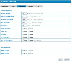
3. Advanced
Select Wi-Fi Setting→Advanced, the advanced wireless network
parameters are shown in the following figure:
31
Beacon Interval: The router broadcasts beacon message to
announce that it has buffered frames to deliver. The default value
is 100 (ms). Beacons are packets sent by an access point to
synchronize a wireless network. Specify a beacon interval value.
is recommended.
Data Beacon Rate(DTIM) : A Delivery Traffic Indication
Message(DTIM) informs next clients to listen to broadcast and
multicast messages.
Fragment Threshold: This value should remain at its default
value of 2346. If you experience a high packet error rate, you
may slightly increase your fragment threshold. Setting the
fragment threshold too low may result in poor performance.
RTS Threshold: Request To Send(RTS) threshold should be
remained as the value of 2347. If you encounter inconsistent
data flow, only minor modifications are recommended.
32
TX Power: Transmit power should be remained as the value of
100.
Short Preamble: The length of CRC block in the frames during
the wireless communication.
Shot Slot: To indicate that 802.11g is using a shot time slot
because there is no legacy station(802.11b) present.
Tx Burst: Tx burst allows router to deliver better throughput in
the same period and environment in order to increase speed.
Pkt_Aggregate: Increase efficiency by aggregating multiple
application packets data into a single transmission frame. In this
way, 802.11n networks can send multiple data packets with the
fixed overhead cost in just a single frame.
IEEE 802.11H Support: Support IEEE 802.11H or not.
The Wi-Fi multimedia parameters are shown below:
WMM Capable: When multimedia contents are transferred over
wireless network, this function enhances data transfer
performance.
APSD Capable: Automatic Power Save Delivery(APSD), enable
or disable data flow using APSD during transmitting for power
saving.
Click Apply to confirm your configuration.
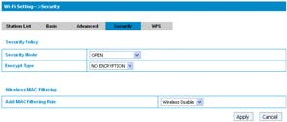
4. Security
Select Wi-Fi Setting→Security, the Security parameters are shown in
the following figure:
33
Unless one of these encryption modes is selected, wireless
transmissions to and from your wireless network can be easily
intercepted and interpreted by unauthorized users.
The security modes are described below:
Open: You can authenticate successfully with a SSID, whether it is
valid or empty.
Shared: The WLAN clients who have the same WEP key with
wireless gateway can pass the authentication and access the
wireless network.
WEPAUTO: Select WEP security automatically.
WPA-PSK: WPA Pre-Shared Key, Enter the Pre-Shared key as a
plain text (ASCII) pass-phrase of at least 8 characters.
WPA2-PSK:It is the securer version of WPA with implementation
of the 802.11i standard.
WPA-PSK/WPA2-PSK:Apply both the WPA-PSK and WPA2-PSK
scheme.
34
If the Authentication type is Open, Shared, WEPAUTO, the bottom
part of the configuration page displays parameters as shown.
WEP Keys: At most four keys can be set in the blank. Choose the
primary key index. The primary key is the only key in use at a
given time. Whatever keys you enter for an access point, you
must also enter the same keys for the client adapter in the same
order. In other words, WEP key 1 on the AP must match WEP
key 1 on the client adapter, WEP key 2 on the AP must match
WEP key 2 on the client adapter, etc. A WEP is either 10 or 26
hexadecimal digits (0~9,a~f and A~F)based on whether you
select 64 bits 128 bits in the Encryption Strength drop-down list.
If the Authentication type is WPA-PSK , WPA2-PSK or WPA-
PSK/WPA2-PSK , the bottom part of the configuration page displays
WPA parameters.
WPA Algorithm: TKIP, AES or AUTO.
Pass phrase: You can input hexadecimal digits up to 64
characters or input ASCII characters choose a length of 63
characters or less.
Key Renewal Interval: Define how long the key should be renew.
You can set Wireless MAC Filtering:
Wireless Disable: If disabled, MAC address is not used to
control network access.
Wireless Allow: Set the MAC address that is allowed to access
network.
Wireless Reject: Set the MAC address that is not allowed to
access network.
35
Click Apply to confirm your configuration.
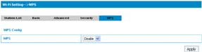
5. WPS
Select Wi-Fi Setting→WPS, the WPS configuration is shown in the
following figure:
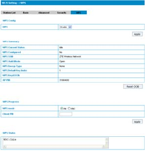
Select Enable ,click Apply ,the WPS settings are shown in the
following figure:
36
WPS Summary, WPS Progress and WPS Status are all shown in the
figure.
To set WPS, Select WPS mode, the two modes are described below:
PIN
37
There are two ways to use PIN mode,one is set PIN code on the
client's wireless adapter(you can find the PIN code in AP PIN field of
WPS Summary), the other way is set the client's PIN code in Client
PIN field.
PBC
Press the WPS button of the router or select PBC, and then click
Apply. Press WPS button on the client wireless adapter within two
minutes, and the negotiation process will be established.
4.2.6 Firewall
You may setup firewall rules to protect your network from virus, worm
and malicious activity on the Internet.
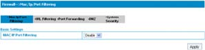
1. MAC/IP/Port Filtering
Select Firewall→Mac/Ip/Port Filtering, the Mac/IP/Port Filtering is
shown in the following figure:
If you select Enable, the filter settings will appear:
38
Default Policy: Set how to handle the packet if none of the rules
matches.
MAC address: Set the MAC address that will be filtered.
Dest IP Address: Set the destination IP address that will be
filtered.
Source IP Address: Set the source IP address that will be filtered.
Protocol: Set which protocol will be used for filtering.
Dest Port Range: Set the destination port numbers that will be
filtered
Source Port Range: Set the source port numbers that will be
filtered.
39
Action: Set how to handle the packet if it matches with the rule.
Comment: type comment for the filter settings.
Click Apply to confirm your configuration.
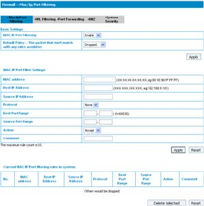
2. URL Filtering
You can setup content filter to restrict the improper content access.
Select Firewall→URL Filtering, the URL Filtering is shown in the
following figure:
Type URL address, and then click Add to add the URL address into the
filtering list. The new URL filtering item will be shown in the Current
Webs URL Filters: field.
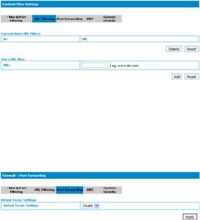
3. Port Forwarding
You can setup virtual servers to provide services on the Internet.
Select Firewall→Port Forwarding, the virtual server settings is shown
in the following figure:
40
If you select Enable, the Virtual Server Settings will appear:
IP Address: Set IP address for the virtual server.
Port Range: Set port numbers for the virtual server.
Protocol: Set protocol for the virtual server.
Comment: Type comment for the virtual server settings.
Click Apply to confirm your configuration.
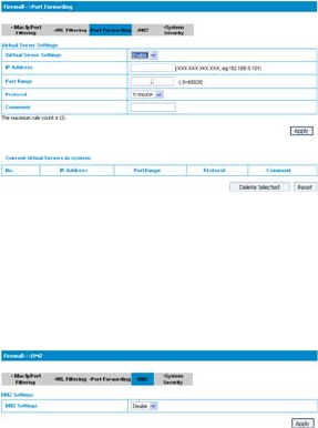
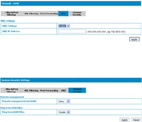
4. DMZ
You can setup a De-militarized Zone(DMZ) to separate internal
network with the Internet. Select Firewall→DMZ, the DMZ setting is
shown in the following figure:
If you select Enable , set the DMZ IP address ,and then click Apply to
confirm your configuration.
41
5. System Security
You can configure system firewall to protect AP or router from being
attacking. Select Firewall→System Security, the system security
setting is shown in the following figure:
Allow or Deny the remote management function and Enable or
Disable ping from WAN filter on requirement, and then click Apply.
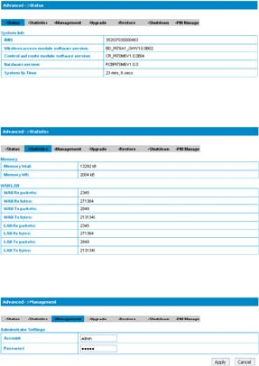
4.2.7 Advanced
1. Status
Select Advanced→Status, the system information is shown in the
following figure:
42
2. Statistics
Select Advanced →Statistics, the system statistics information is
shown in the following figure:
3. Management
Select Advanced→Management, the administrator settings
information is shown in the following figure:
To set new account, type new account and password, and then click
43
Apply to confirm your configuration.
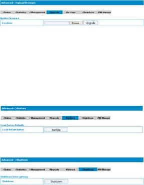
4. Upgrade
Select Advanced→Upgrade to upgrade the software version of the
router.
Click Browse..., locate the latest software version, and then click
Upgrade.
Note: Do not upgrade software unless necessary. Wrongly upgrade
action may cause router malfunction or can not work.
5. Restore
Select Advanced→Restore, click Restore to set all the settings to
their factory default values, and the device will be turned off.
6.Shutdown
Select Advanced→Shutdown, click Shutdown to turn the router off.
44
Note: Router is powered off only when the PWR indicator is off. And do
not press the power switch during the shutdown process.
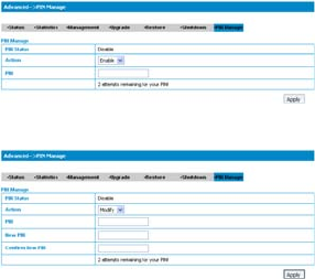
7. PIN Manage
Select Advanced→PIN Manage, the PIN manage is shown in the
following figure:
If you select Modify, the modification parameters are shown in the
following figure:
Type the old PIN code, and then type two times the new PIN code.
Click Apply to confirm your configuration.
Note: Three time consecutive wrong PIN code entries will lock the SIM
card.
4.3 Logout
Select Logout, a pop-up windows will appear as shown in the
45
following figure :
Click OK to logout the router.
4.4 Disconnecting from the Internet
If you want to terminate your Internet connection, you can select
Disconnect Internet from WAN Connection page, and click Submit.
Turn off the router can also terminate Internet connection.

46
5 Troubleshooting
1) Make sure that the router is turned on and all the cables are
connected correctly.
2) Check the RSSI, PPP and PWR LED’s are lit and NOT in a blinking
state or off.
A) Voice Related Problems
Symptoms Possible Problems/ Solutions
No Dial Tone.
Please wait for 1~2 minutes
after the router is turned on.
If RSSI is blinking, you have no
good RF reception. Change the
location of the router.
There is a prompt/ phone alert/
announcement as soon as I lift
the phone off the hook.
Make sure your (U)SIM card is
inserted correctly and the PIN
number has been entered. If the
PIN number has been entered
incorrectly then you will need to
enter the PUK code when
prompted.
The line is noisy/ distorted when
I lift the phone off the hook. Remove any electrical appliance
which is too close to the phone
or router.
The cable or phone set might be
faulty.
I hear a rapid engaged tone as
soon as I lift the phone off the
hook.
Put the phone on hook and try
again. If you are connected to
the internet using the 2G (GSM)
network, please disconnect this
first.

47
Symptoms Possible Problems/ Solutions
After dialing the last digit I hear
nothing /silence.
When you have finished dialing
you can press the # key or wait
4-8 seconds to connect the call.
I can’t make or receive a call
when I am surfing on the net.
If you are connected using the
2G (GSM) network then you
cannot surf the net and make a
phone call simultaneously.
Please disconnect the internet
and wait 30 seconds to 1 minute
before making a call.
B) Internet Related Problems
Symptoms Possible Problems/ Solutions
I cannot access the internet at
all.
Please check your configuration
settings.
Please wait 1~ 2 minutes for the
router to initialize.
Check your service indicator
LED’s.
The download or upload speeds
are very slow.
The speed is dependent on
signal strength. Check your
signal strength and network
type.
C) Others
Symptoms Possible Problems/ Solutions
The RSSI signal indicator is
always blinking or does not light.
This indicates poor reception.
Try moving the router to another
location near the window.
48
6 Technical Parameters
Network & Frequency Band:
EDGE/GPRS/GSM: 850/900/1800/1900MHz
HSUPA/HSDPA/UMTS: 850/1900/2100MHz
LED Display:
a. Power Indicator
b. Wi-Fi Indicator
c. PPP Indicator
d. Radio Signal Strength Indicator
External Interface:
a. External Power Socket
b. Phone Interface (PHONE)
c. Data Interface (LAN)
d. Test Interface (Mini-USB)
Power Adapter:
Input: 100V~240V (AC), 50/60Hz
Output: +12V (DC), 1.5A Max
Data Service:
HSUPA 2Mbps UL
HSDPA 7.2Mbps DL
Dimensions (W×H×D): 160mm×112mm×32mm
Weight: About 500g
49
Copyright © 2009 by ZTE Corporation
All rights reserved.
No part of this publication may be excerpted, reproduced,
translated or utilized in any form or by any means, electronic or
mechanical, including photocopying and microfilm, without the prior
written permission of ZTE Corporation.
The manual is published by ZTE Corporation. We reserve the
right to make modifications on print errors or update specifications
without prior notice.