ZTE ZXMBW-E9230 Compact Base Station (Outdoor) User Manual
ZTE Corporation Compact Base Station (Outdoor) Users Manual
ZTE >
Users Manual

ZXMBWE9230
CompactBaseStation(outdoor)
UserManual
ZTECORPORATION
ZTEPlaza,KejiRoadSouth,
Hi-TechIndustrialPark,
NanshanDistrict,Shenzhen,
P .R.China
518057
Tel:(86)75526771900
Fax:(86)75526770801
URL:http://ensupport.zte.com.cn
E-mail:support@zte.com.cn

LEGALINFORMATION
Copyright©2006ZTECORPORATION.
Thecontentsofthisdocumentareprotectedbycopyrightlawsandinternationaltreaties.Anyreproductionordistributionof
thisdocumentoranyportionofthisdocument,inanyformbyanymeans,withoutthepriorwrittenconsentofZTECORPO-
RATIONisprohibited.Additionally,thecontentsofthisdocumentareprotectedbycontractualcondentialityobligations.
Allcompany,brandandproductnamesaretradeorservicemarks,orregisteredtradeorservicemarks,ofZTECORPORATION
oroftheirrespectiveowners.
Thisdocumentisprovided“asis” ,andallexpress,implied,orstatutorywarranties,representationsorconditionsaredis-
claimed,includingwithoutlimitationanyimpliedwarrantyofmerchantability,tnessforaparticularpurpose,titleornon-in-
fringement.ZTECORPORATIONanditslicensorsshallnotbeliablefordamagesresultingfromtheuseoforrelianceonthe
informationcontainedherein.
ZTECORPORATIONoritslicensorsmayhavecurrentorpendingintellectualpropertyrightsorapplicationscoveringthesubject
matterofthisdocument.ExceptasexpresslyprovidedinanywrittenlicensebetweenZTECORPORATIONanditslicensee,
theuserofthisdocumentshallnotacquireanylicensetothesubjectmatterherein.
ZTECORPORATIONreservestherighttoupgradeormaketechnicalchangetothisproductwithoutfurthernotice.
UsersmayvisitZTEtechnicalsupportwebsitehttp://ensupport.zte.com.cntoinquirerelatedinformation.
TheultimaterighttointerpretthisproductresidesinZTECORPORATION.
RevisionHistory
RevisionNo.RevisionDateRevisionReason
R1.107/15/2009OptimizeManaul
R1.005/15/2009FirstEdition
SerialNumber:sjzl20092846

Contents
Preface...............................................................i
ProductOverview..............................................1
ZXMBWE9230PositionintheNetwork..............................1
Functions......................................................................2
Appearance...................................................................3
FundamentalPrinciple.....................................................3
ExternalInterfaces.........................................................4
NetworkingApplication....................................................6
TechnicalIndices............................................................7
EngineeringIndices....................................................7
PerformanceIndices...................................................8
ClockParameter.........................................................9
EnvironmentalIndices.................................................9
ComplianceStandards....................................................10
ProtocolInterfaceDescription..........................................10
ASNNetworkReferenceModel.....................................10
ProtocolInterfaces.....................................................11
R1Interface.............................................................12
R6Interface.............................................................14
HardwareDescription......................................19
CabinetStructure..........................................................19
HardwareModules.........................................................21
MTRWModule...............................................................21
WDPAModule...............................................................21
WRFEModule................................................................22
WRPMModule...............................................................23
EquipmentInstallation....................................25
ComponentstobeInstalled...........................................25
InstallationFlow............................................................25
InstallationPrecautions..................................................26
InstallationPreparation..................................................27
InstallationEnvironmentCheck...................................27
InstallationPositionRequirements...............................27
TemperatureandHumidityRequirements......................28
PowerSupplyRequirements........................................28
OtherPreparation......................................................28
ToolsandInstrumentsPreparation...............................29
InstallingCabinets.........................................................30
InstallationModeIntroduction.....................................30
InstallingaWall-MountCabinet...................................34
InstallingaPole-MountCabinet...................................39
InstallingExternalCables...............................................47
InstallingPowerCable................................................47
InstallingGroundingCable..........................................49
InstallingRFJumper..................................................50
InstallingAntenna.....................................................51
InstallingFeederGroundingKit...................................54
PerformingOutdoor-connectorWaterproof
Processing........................................................55
VSWRTest................................................................60
CabinetInstallationCheck..............................................60
CabinetInstallationCheck..........................................60
On-siteEnvironmentInspectionItems..........................61
Power-on......................................................................61
Figures............................................................63
Tables.............................................................65

Preface
PurposeZXMBWE9230isanoutdoorcompactbasestationandoneof
WiMAXbroadbandradioaccessproducts.ItprovidesIP-based
voiceandvideoservicesinhotspots,blindspots,ruralandsub-
urbs,railwaysandhighways.
Thismanualdescribessystemcompositions,functions,principle,
networking,technicalindicesandengineeringinstallationofthe
ZXMBWE9230.
Intended
AudienceThisdocumentisintendedforengineersandtechnicianswhoper-
formoperationandinstallationactivitiesontheZXMBWE9230.
PrerequisiteSkill
andKnowledgeTousethisdocumenteffectively,usersshouldhaveageneralun-
derstandingofwirelesstelecommunicationstechnology.Familiar-
itywiththefollowingishelpful:
�TheZXMBWE9230systemanditsvariouscomponents
�UserinterfacesontheZXMBWE9230
�Localoperatingprocedure
WhatisinThis
ManualThismanualcontainsthefollowingchapters.
ChapterSummary
Chapter1ProductOverviewIntroducestheposition,functions,
principles,externalandinternal
interfaces,applicationsand
technicalindicesoftheZXMBW
E9230.
Chapter2HardwareDescriptionDescribesthecabinetstructure,
hardwaremodules,antenna
feedersystemandexternalcables
oftheZXMBWE9230.
Chapter3EquipmentInstallationDescribestheinstallation
ow,installationpreparation,
cabinetinstallation,power
cableinstallation,hardware
installationcheck,andpower-on
andpower-offproceduresofthe
ZXMBWE9230.
FCCCompliance
StatementThisdevicecomplieswithpart15oftheFCCRules.Operationis
subjecttothefollowingtwoconditions.
1.Thisdevicemaynotcauseharmfulinterference.
2.Thisdevicemustacceptanyinterferencereceived,including
interferencethatmaycauseundesiredoperation.
Changesormodicationsnotexpresslyapprovedbythepartyre-
sponsibleforcompliancecouldvoidtheuser'sauthoritytooperate
theequipment.
CondentialandProprietaryInformationofZTECORPORATIONi

ZXMBWE9230UserManual
Thispageisintentionallyblank.
iiCondentialandProprietaryInformationofZTECORPORATION
Chapter1
ProductOverview
TableofContents
ZXMBWE9230PositionintheNetwork..................................1
Functions..........................................................................2
Appearance.......................................................................3
FundamentalPrinciple.........................................................3
ExternalInterfaces.............................................................4
NetworkingApplication........................................................6
TechnicalIndices................................................................7
ComplianceStandards........................................................10
ProtocolInterfaceDescription.............................................10
ZXMBWE9230Positionin
theNetwork
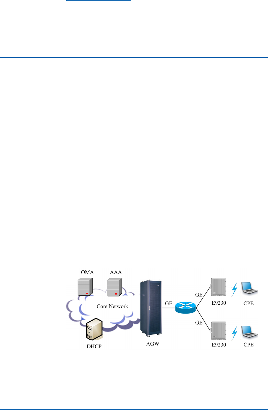
ZXMBWE9230islocatedintheradioaccesslayerofWiMAXnet-
worksandusedtoprovidebroadbandradioaccessforusersin
outdoorhotandblindspots,suburbs,ruralareas,railwaysand
highways.
Figure1showsthepositionoftheZXMBWE9230intheWiMAX
network.
FIGURE1ZXMBWE9230POSITIONINTHENETWORK
Table1describesthemeaningsoftheseNEs.
CondentialandProprietaryInformationofZTECORPORATION1

ZXMBWE9230UserManual
TABLE1NEMEANING
NEMeaning
AAAAuthentication,Authorization,Accounting
AGWAccessServiceNetworkGateway
E9230CompactBaseStation(outdoor)
CPECustomerPremisesEquipment
DHCPserverDynamicHostCongurationProtocolserver
OMAOperation,MaintenanceandAdministration
Functions
TheZXMBWE9230providesthefollowingfunctions.
ForwardSignal
Processing�PerformsOFDMAmodulation,MAClayerprocessing,digi-
talup-conversion,intermediatefrequencyamplication,RF
poweramplicationandtransmitlteringonreceivedbase-
bandsignalsandthentransmitsthembyusingtheantenna.
�ImplementsMAClayerschedulingandpowercontrol.
�Detectsbasebandsignalpowerandantennainterfacepowerin
FPGAofthedigitaldomain.
�Accomplisheswavestandingratiodetectionontheforwardan-
tennainterface.
�Implementsforwardautomaticcalibrationandmanualcalibra-
tion.
ReverseSignal
Processing�ReceivesreverseRFWiMAXsignalsfromspaceandperforms
bandpassltering,lownoiseamplication,RFRFmixingand
digitaldown-conversiononthesesignalsandthensendsthem
tothebasebandOFDMAmodulationandMAClayerprocessing.
Afterwards,thebasebandsendsthesesignalstoAGWthrough
theR6interfaceforinterconnectionwiththecorenetwork.
�SupportsreverseRSSIandreversespectrumscanfunctions.
�Accomplishesreverseautomaticgaincontrol.
ClockProcessing�ImplementsGPSclocksignalabstractionandclockrecovery.
�Supportsclockcascading.
�Accomplishesclocksignaldistribution.
OtherFunctions�MonitorsandmanagesWDPAsignals.
�Monitorsandmanagesthepowersupply.
�Monitorsandmanagestheelectricallytunedantenna.
�MonitorsexternalequipmentsthroughdrycontactsandRS485
interface.
�ImplementsTDDtimesequenceregeneration.
�Accomplishesversionmonitoringandversionmanagement.
2CondentialandProprietaryInformationofZTECORPORATION
Chapter1ProductOverview
�Implementsmaster/slaveR6interfaceprocessingandR6in-
terfaceEthernetconvergence.
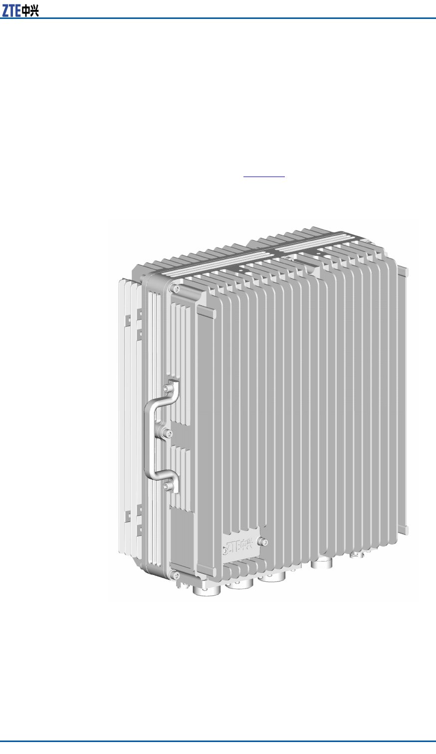
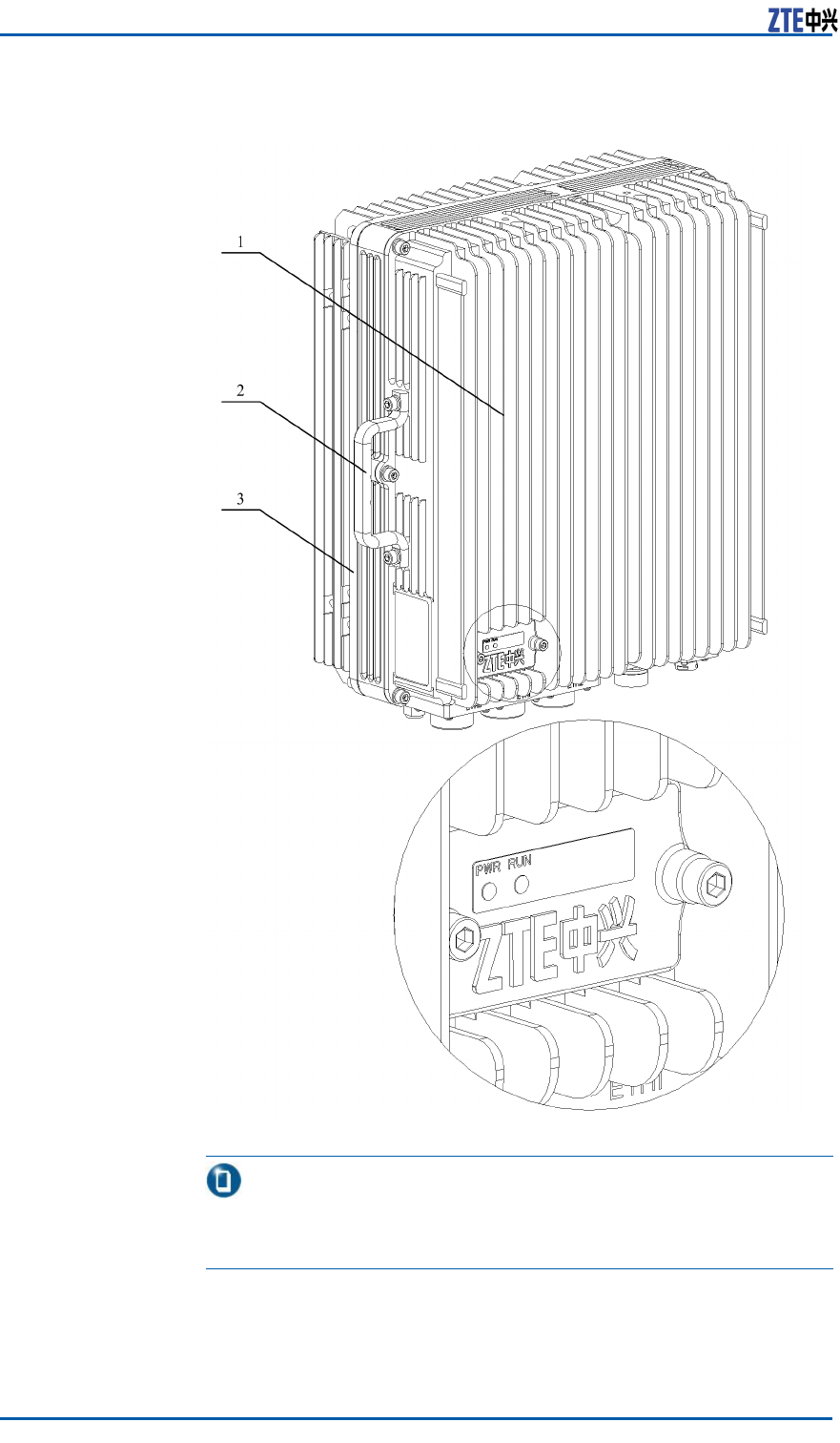
Appearance
ThedimensionsoftheZXMBWE9230cabinetare370mm(W)×
320mm(D)×165mm(H).Figure2showstheZXMBWE9230ap-
pearance.
FIGURE2ZXMBWE9230APPEARANCE
FundamentalPrinciple
TheZXMBWE9230implementstheradioaccessfunctionforout-
doorcoveragesystems.
Itprovidesthefollowingfunctions:
CondentialandProprietaryInformationofZTECORPORATION3
ZXMBWE9230UserManual
�ExchangesradiosignalswiththeATsinitscoveragethrough
theWiMAXairinterfaceandcontrolsradiochannels.
�CommunicateswithBTSs.
�Modulatesanddemodulatesbasebandsignals.
�Implementssystemclocksynchronization.
�ReceivesandtransmitsRFsignals.
�Implementspowercontrol.
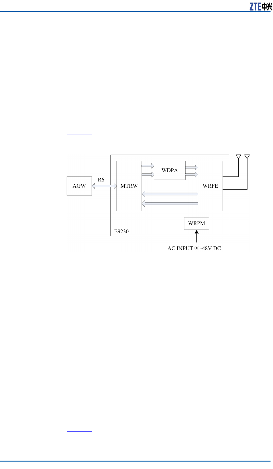
TheZXMBWE9230iscomposedofabasebandintermediatefre-
quencyboard(MTRW),adigitalpredistortionhighpoweramplier
(WDPA),anRFfrontendlter(WRFE)andpowermoduleWRPM.
Figure3illustratestheZXMBWE9230composition.
FIGURE3ZXMBWE9230COMPOSITION
TheZXMBWE9230processesthefollowingbasicservices:
�Forwardservice
ThecorenetworksendsIPpacketstotheZXMBWE9230
throughthetransmissionnetwork.Afterreceivingthesepack-
ets,theMTRXunitoftheZXMBWE9230disassemblesthem
andthensendstothebasebandprocessunitforencodingand
modulation.Afterwards,theseIPpacketsaresenttotheRF
processunitforup-conversionandpoweramplicationbefore
beingtransmittedtoATs.
�Reverseservice
ThesignalsfromATsaredownconvertedbytheRFprocessunit
oftheZXMBWE9230andthensenttothebasebandprocess
unitforchannelmodulation.Afterwards,thesesignalsaresent
totheCPUcontrolunitforIPpackingandthentransmittedto
thecorenetworkthroughthetransmissionnetwork.
ExternalInterfaces
Figure4showstheexternalinterfacesoftheZXMBWE9230.
4CondentialandProprietaryInformationofZTECORPORATION
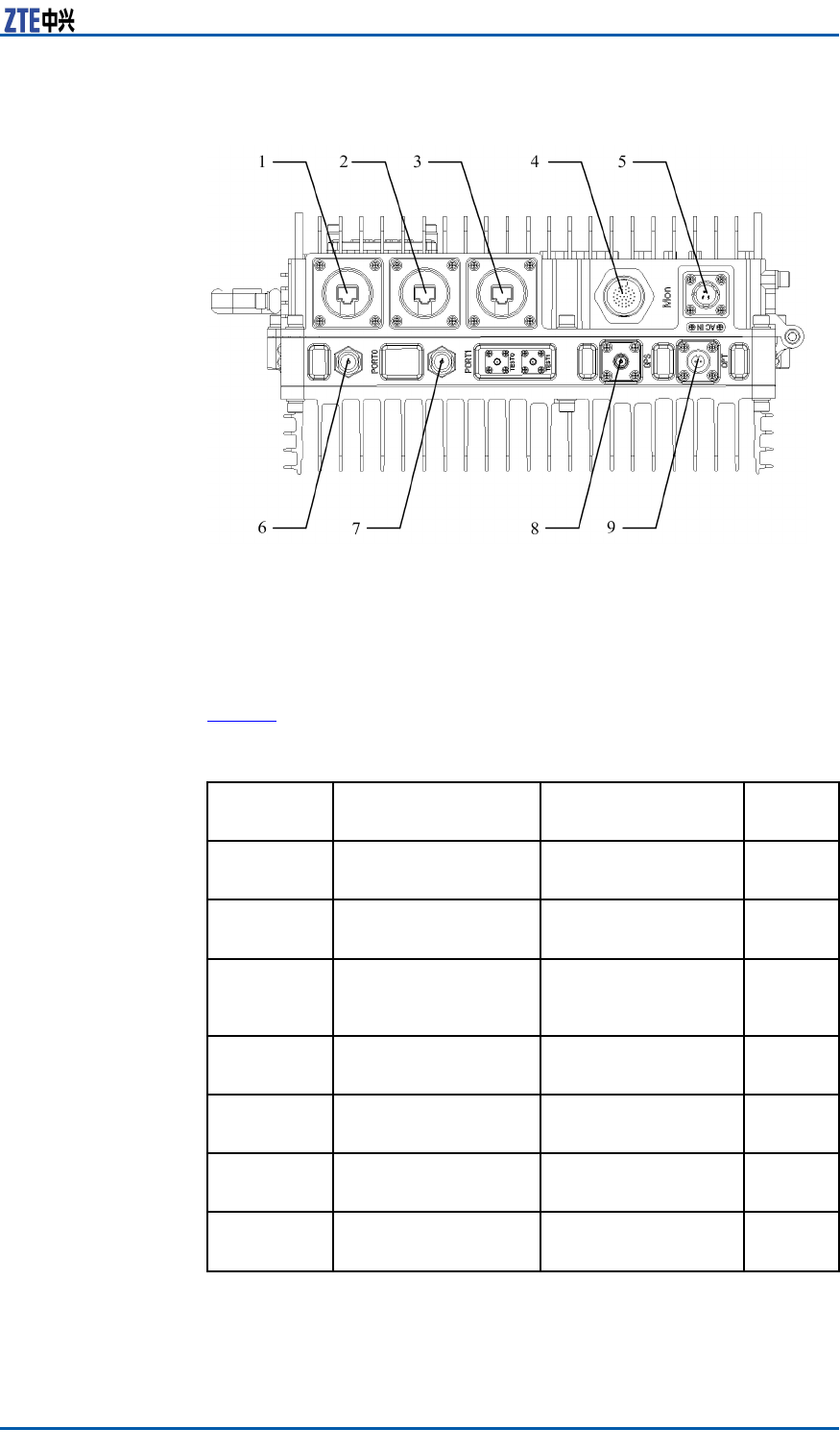
Chapter1ProductOverview
FIGURE4EXTERNALINTERFACES
1.GigabitEthernetelectricalinter-
face
2.GigabitEthernetelectricalinter-
face
3.GigabitEthernetelectricalinter-
face
4.Monitoring&maintenancecascade
interface
5.Powerinterface
6.RFantennafeederinterface
7.RFantennafeederinterface
8.GPSantennainterface
9.GigabitEthernetopticalinterface
Table2describestheseexternalinterfaces.
TABLE2EXTERNALINTERFACEDESCRIPTION
Sequence
No.
Interface
Description
ConnectorQuan-
tity
1Electricallytunedan-
tennainterface
8–coreaerialconnec-
tor
1
1,2and3GigabitEthernetelec-
tricalinterface
Electricalinterface
connectorassembly
3
4Monitoring&mainte-
nancecascadeinter-
face
37–coreaerialcon-
nectorassembly
1
5DCpowerinterfacePowerconnectoras-
sembly
1
6and7RFantennafeederin-
terface
N-female2
8GPSantennainter-
face
TNC-female1
9GigabitEthernetopti-
calinterface
Opticalinterfacecon-
nectorassembly
1
–TheETH0interfacewithsequenceNo.of1issharedbyR6interfaceand
electricallytunedantennainterface.Theinterfaceisusedfordifferent
purposesaccordingtothecongurationrequirement.
CondentialandProprietaryInformationofZTECORPORATION5
ZXMBWE9230UserManual
Note:
TheelectricallytunedantennainterfaceandtheR6interfacethat
thestarnetworksupportsaremutuallyexclusive.Inthecaseof
electricallytunedantenna,ETH0isoccupied.Inthiscase,onlythe
R6interfacedaisycascadingissupportedwhiletheR6interface
starcascadingisnotsupported.
NetworkingApplication
TheZXMBWE9230supportsmultiplenetworkingapplications.
ZXMBWE9230
Independent
Networking
Application
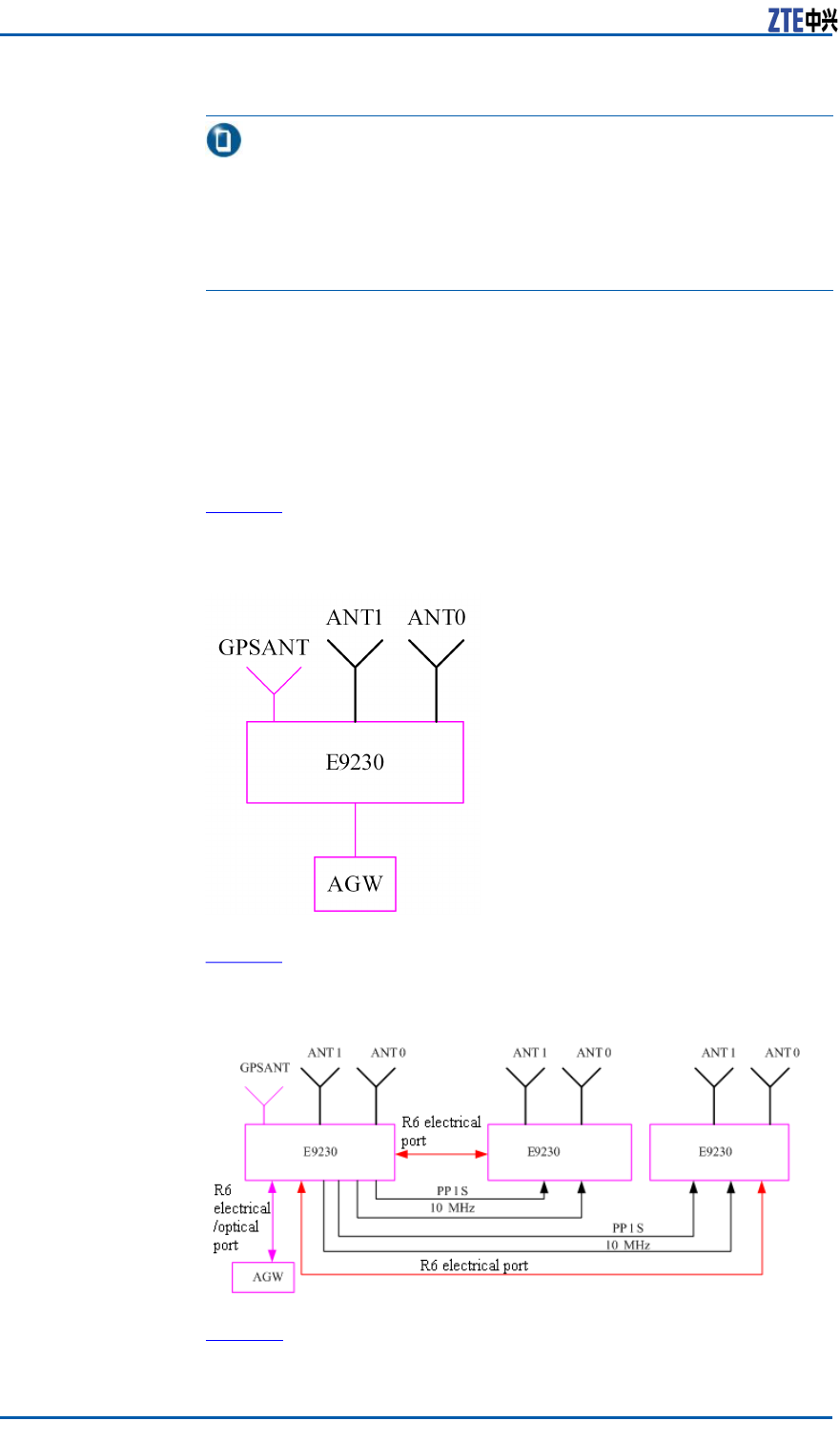
Figure5illustratestheZXMBWE9230independentnetworkingap-
plication.
FIGURE5INDEPENDENTNETWORKINGAPPLICATION
StarNetworking
ApplicationFigure6illustratestheZXMBWE9230R6interfacestarnetworking
application.
FIGURE6ZXMBWE9230STARNETWORKINGAPPLICATION
DaisyNetworking
ApplicationFigure7illustratestheZXMBWE9230R6interfacedaisynetwork-
ingapplication.
6CondentialandProprietaryInformationofZTECORPORATION
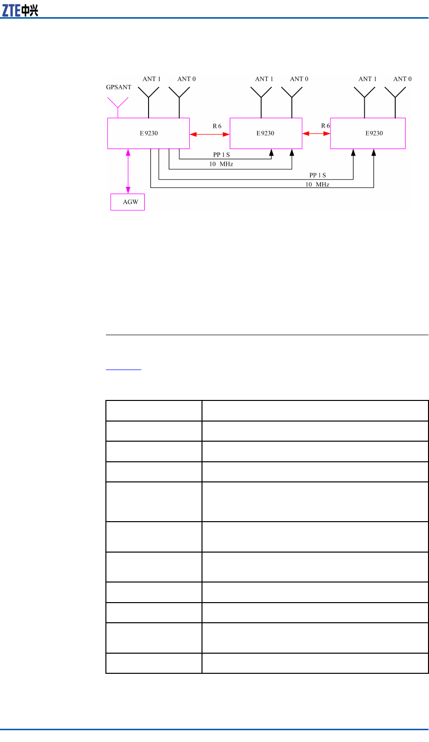
Chapter1ProductOverview
FIGURE7ZXMBWE9230DAISYNETWORKINGAPPLICATION
TechnicalIndices
EngineeringIndices
Table3givesZXMBWE9230engineeringindices.
TABLE3ENGINEERINGINDICES
IndexDescription
Dimension370mm(W)×320mm(D)×165mm(H)
Weight15kg
PowerSupply-48VDC
Temperatureof
workingenviron-
ment-40℃~55℃
Humidityofwork-
ingenvironmentRelativehumidityrange:5%~95%
Overallpowercon-
sumption<200W
ProtectionlevelIP65
Overallsize<20litres
Overallpowerof
powersupply
<200W
HeatdissipationSelf-cooling
CondentialandProprietaryInformationofZTECORPORATION7

ZXMBWE9230UserManual
PerformanceIndices
Table4liststheperformanceindicesofZXMBWE9230.
TABLE4PERFORMANCEINDICES
IndexDescription
Bandclass2496MHz~2690MHz
RFCarrier
bandwidth
5MHzand10MHz1–carriersupport
2x10MHzand2x5MHz2–carrier
support
Duplex
modeFDD/TDDTDD
Carrier1carrieror2carriers
MIMO2×2MIMO
System
indices
Outputpower2x40dBm(10W)
ModulationmodeQPSK,16QAMand64QAM
AntennaElectricallytunedantenna(optional)
R6interfaceOpticalinterfaceorelectricalinterface
OverallnoiseNonoise
Maintenance
Itsupportsremoteupgrading.
ItsupportsthelocalOMCandDebug
interface.
Environmentalprotection
ItmeetstheRestrictionoftheUse
ofcertainHazardousSubstancesin
ElectricalandElectronicEquipment
(ROHS)andWasteElectricaland
ElectronicEquipmentDirective(WEEE)of
theEuropeanUnion.
HeatdissipationSelf-cooling
Followedstandards
IEEE802.16-2005
WiMAXForumTMMobileRadio
ConformanceTests
LightningprotectionDC:Abuilt–in15KAlightningarrester
meetsthelevelCrequirement.
InstallationmodeItsupportsoutdoorpole—mount
installationandwall-mountinstallation.
8CondentialandProprietaryInformationofZTECORPORATION

Chapter1ProductOverview
ClockParameter
TheZXMBWE9230supports3levelsofmaster/slaveclockcas-
cading.
EnvironmentalIndices
Table5givestheenvironmentalindicesoftheZXMBWE9230.
TABLE5ENVIRONMENTALINDICES
IndexDescription
Workingenvironment
Outdoorareas(higher
than4K2)/4Z5/4Z7/4
B1/4C2/4S3/4M3
PlantsAnti-mouldandanti-
fungus
Biologicalenvironment(4B1)
AnimalsAnti-rodentbutnot
anti-termites
Chemicalmaterialcondition(4C2)SaltfogSaltsprayproong
Sandmg/m31000
Dust(oating)mg/m315
Mechanicalma-
terialconditions
(4S3)
Dust(sinking)mg/m2.
d1000
Temperature℃-40~55
Relativehumidity%5~95
Temperature
changerate℃/min0.5
PressurekPa70~106
SolarradiationW/m21120
DewdropItmeetsthedewdrop
requirement.
Precipitation
(rain,snowand
hail)
Itmeetstheprecipita-
tionrequirement.
Rainfallintensitymm/mi-
n6
Rainwatertem-
perature℃5
Climaticenvi-
ronment
CondentialandProprietaryInformationofZTECORPORATION9

ZXMBWE9230UserManual
IndexDescription
Freezingand
frost
Itmeetsthefreez-
ingandfrostrequire-
ment.
Maximumwind
speedm/s50
ComplianceStandards
TheZXMBWE9230complieswiththefollowingstandards:
�IEEEStandard802.16-2005Part16:AirInterfaceforFixedand
MobileBroadbandWirelessAccessSystems
�WiMAXForumTMMobileRadioConformanceTests(MRCT)
�WiMAXForumTMMobileProtocolImplementationConformance
Statement(PICS)Proforma
�WiMAXForumTMMobileSystemProle
ProtocolInterface
Description
ASNNetworkReferenceModel
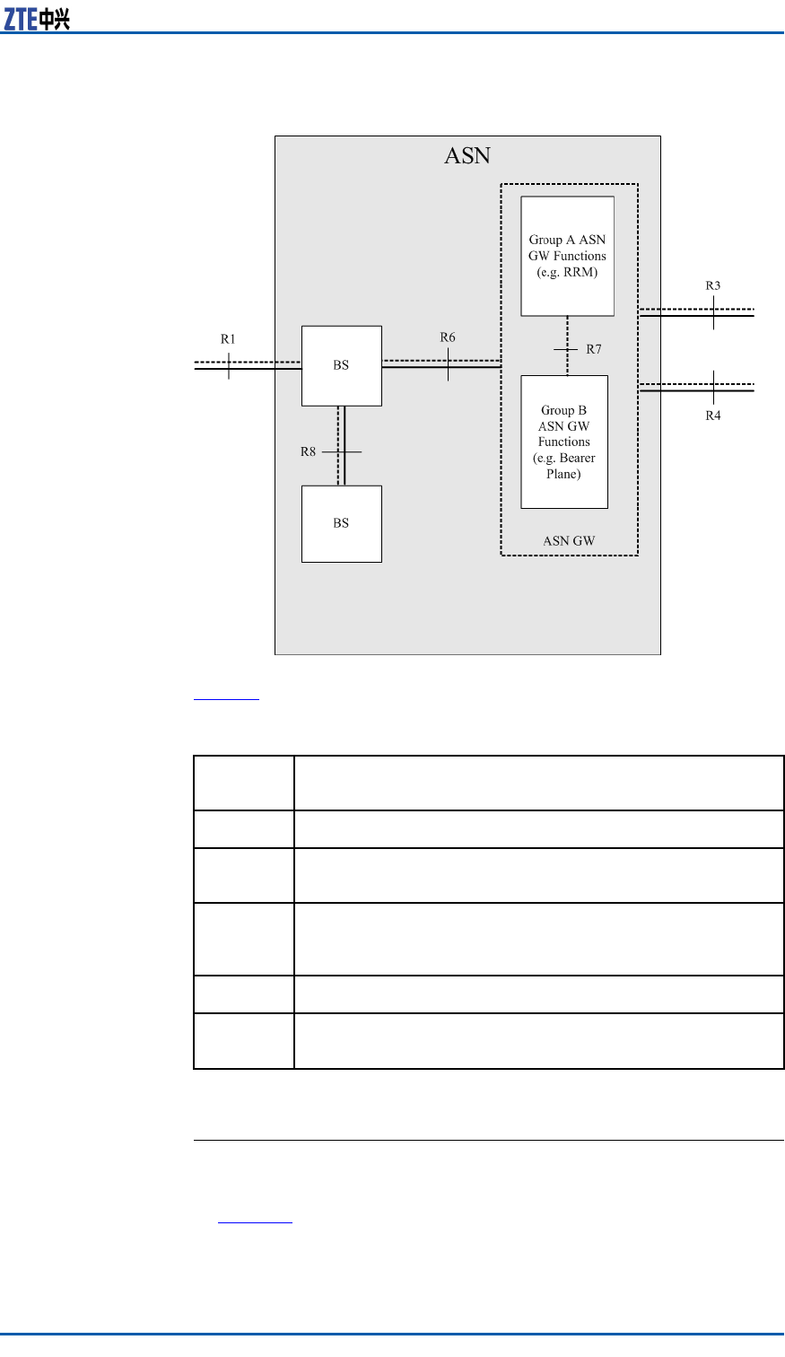
Figure8illustratestheASNnetworkreferencemodelformulated
byWiMAXNWG.
10CondentialandProprietaryInformationofZTECORPORATION
Chapter1ProductOverview
FIGURE8ASNNETWORKREFERENCEMODEL
Table6describestheseinterfaces.
TABLE6ASNINTERFACEDESCRIPTION
Inter-
face
Description
R1AirinterfacebetweenATandRRU
R3InterfacebetweenAGW(alsocalledAccessService
NetworkGateWay(ASN-GW))andthecorenetwork
R4InterfacebetweenASNsorAGWs.Itimplementshandoff
relatedsignalinganddatachannelthatissetupto
maintaindataconsistencyduringhandoff.
R6InterfacebetweenAGWandBTS
R7(Optional)InternalinterfaceofAGW .ItdividesAGWinto
thepolicydecisionpartandthepolicyrealizationpart.
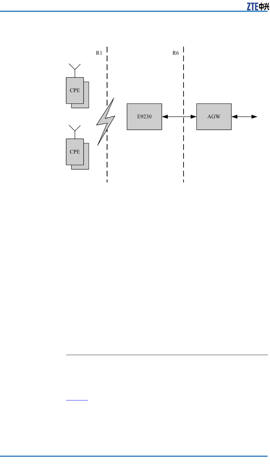
ProtocolInterfaces
ZXMBWE9230supportsR1interfaceandR6interface,asshown
inFigure9.
CondentialandProprietaryInformationofZTECORPORATION11
ZXMBWE9230UserManual
FIGURE9ZXMBWE9230INTERFACES
Thefollowingisthedescriptionoftheinterfaces.
�R1interface
R1interfaceistheinterfacebetweentheBSandtheMS,con-
tainingMAClayer ,physicallayerandrelevantmanagement
plane.Itcomplieswiththe802.16eprotocol.
�R6interface
R6interfaceisbetweentheBSandtheAGW .Itcontainsthe
dataplaneandcontrolplane.
�Dataplane
DataplaneistheIPtunnelbetweentheAGWandtheBS.It
isusedtodifferentiatethetrafcowswithdifferentQuality
ofService(QoS)levels.
�Controlpane
Controlplanesupportsthetunnelmanagement,Authen-
tication,Authorization,Accounting(AAA)andRadioRe-
sourceManagement(RRM)functions.
R1Interface
ShortDescriptionR1interfaceistheinterfacebetweentheBSandtheMS,contain-
ingMAClayer ,physicallayerandrelevantmanagementplane.It
complieswiththe802.16eprotocol.
MessageFormatT able7describestheMAClayermanagementmessageformatof
theR1interface.
12CondentialandProprietaryInformationofZTECORPORATION

Chapter1ProductOverview
TABLE7R1MESSAGEFORMAT
ContentDescription
MessageT ype
Thersteldofeverymanagementmessageis
MessageType.Toknowthevalueofthiseld,
refertothecontentofMACmanagementmessage
intheprotocol.
Non-TLVeld
Thiseldissequencedstrictlyaccordingtothe
denitionofmessageformat.Thecorresponding
valuesofvariouseldsaresortedstrictlyaccord-
ingtothesequencedenedbythemessagefor-
mat.
TLVeld
Thiseldisatripleeld,thatis,type-length-
value.Themessagesortsthetripleofsucheld
accordingtotheactualsituation.
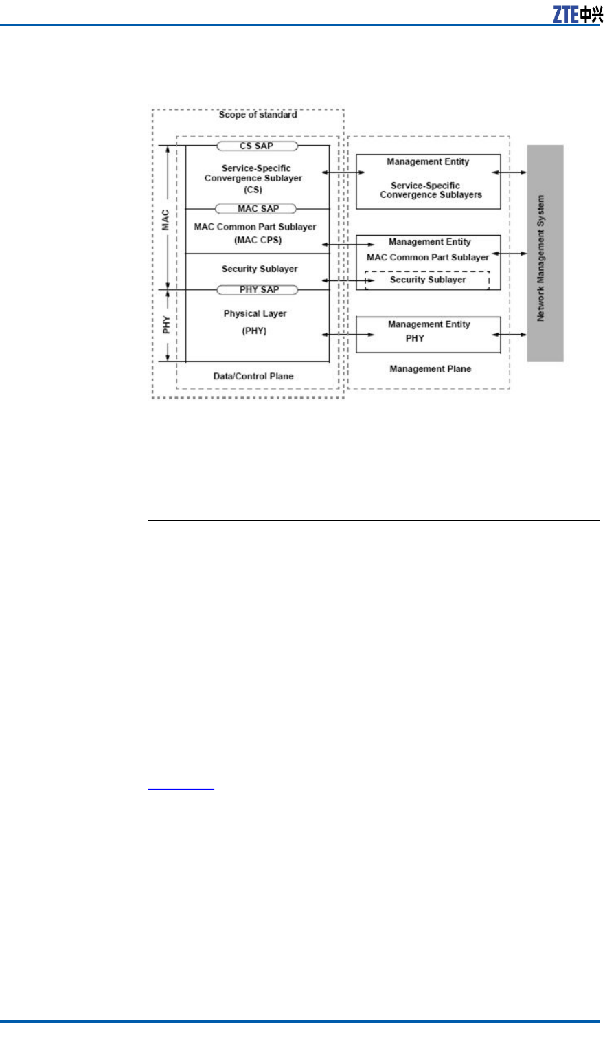
ProtocolStackTheR1interfacecontainsMAClayerandphysicallayer .TheMAC
layercontainsthreesub-layers,thatis,service-specicConver-
genceSub-layer(CS),MACCommonPartSub-layer(MACCPS)
andsecuritysub-layerinthetop-downsequence.
CSsub-layer:TheCSsub-layerconverts/mapstheexternaldata
receivedbyCS-SAPintoMACSDUandtransmitsthedatatoMAC
CPSthroughMACSAP .Thesub-layerclassiesexternalService
DataUnits(SDUs)andassociatesthemwithproperSFIDsand
CIDs.Itsupportsthepayloadheadcompressionfunctionandpro-
videsvariousservice-specicconvergencesub-layerspecications
fordifferentexternalprotocolinterfaces.
MACCPSsub-layer:TheMACCPSsub-layerdoesnotresolvethe
payloadattheCSsub-layer .TheMACCPSsub-layersupports
thecorefunctionsoftheMAClayer ,includingbandwidthrequest,
connectionsetupandmaintenance.Itreceivesdataofvarious
CSsub-layersthroughtheMACSAPandclassiesthesedataby
differentMACconnections.ItsQoSisappliedtotransmissionand
schedulingabovethephysicallayer .
�Securitysub-layer:TheMAClayercontainsanindependent
securitysub-layerthatprovidesauthentication,safekeyex-
changeandencryption.
�Thephysicallayerhasmultiplespecications,eachofwhich
correspondstoaspecicfrequencyrangeandapplication.
Figure10illustratestheR1interfaceprotocolstack.
CondentialandProprietaryInformationofZTECORPORATION13
ZXMBWE9230UserManual
FIGURE10R1INTERFACEPROTOCOLSTACK
PhysicalLayerTheR1interfaceadoptsOrthogonalFrequencyDivisionMultiplex-
ing(OFDM)atthephysicallayer .
R6Interface
R6interfacedenestheprocessingowbetweenBSandASN-GW.
ThesignalingbetweentheBSandtheASN-GWistransmitted
throughtheR6tunnelintheformatofUserDatagramProtocol
(UDP)plusthesignalingformatdenedbyNWGstage3.Theme-
diaplanedataisborneovertheencapsulationtunnelprotocol.
UDPbearsR6signaling.GenericRoutingEncapsulation(GRE),
MultipleProtocolLabelSwitching(MPLS)andVirtualLocalArea
Network(VLAN)bearsR6data.
TheASN-GWterminatestheR6tunnelfromtheBS.TheR6tunnel
canadoptvariousencapsulationtechnologies,suchasGRE,MPLS
andVLAN,anddifferenttunnelgranularitiesareallowed.TheR6
datapathsupportsencapsulationprotocolandtunnelgranularity
negotiation.
ControlPlane
MessageFormatFigure11describesthecontrolplanemessageformatoftheR6
interface.
14CondentialandProprietaryInformationofZTECORPORATION

Chapter1ProductOverview
FIGURE11R6CONTROLPLANEMESSAGEFORMAT
Table8liststhedescriptionoftheeldintheR6controlplane
message(followingthebyteorder).
TABLE8R6CONTROLPLANEMESSAGEFIELDDESCRIPTION
FieldDescription
VersionProtocolversionnumber .
FlagsBytelength.
FunctionTypeIndicatesthefunction,suchasHO
Control.
OPIDIndicatestheoperationtype.
MessageTypeMessagetypecorrespondingto
FunctionType,suchasHO_Req.
LengthMessagelength,includingthe
messagehead.
MSIDMACaddressoftheMSthatis
relatedtothemessage.Ifthe
messageisnotrelatedtoany
specicMS,allbitsofthiseld
aresetto0.
Reserved32reservedbits,whicharesetto
0.
TransactionIDTransactionID.Ifitis0,the
messageshouldbediscarded.
ReservedReservedbit,whichissetto0.
DestinationIdentierTLV
(Type/Length/Value)
Length-variabledestinationentity
identier .Forexample,the
destinationtowhichthemessage
istobesentisthenetwork
nodeIDofafunctionalentity.
Themessagereceiverchecks
whetherDestinationIdentierin
themessageheadisthesameas
itsownIdentierbeforeaccepting
themessage.Ifyes,thereceiver
willprocessthismessage.If
no,thereceiverwilltransit
CondentialandProprietaryInformationofZTECORPORATION15
ZXMBWE9230UserManual
FieldDescription
themessagetothedestination
identierwithoutchangingit.
SourceIdentierTLVLength-variablesourceentity
identier ,forexample,the
networkIDofafunctionalentity
thatoriginatesthemessage.
TLVsAtripletfollowingthemessage
head.
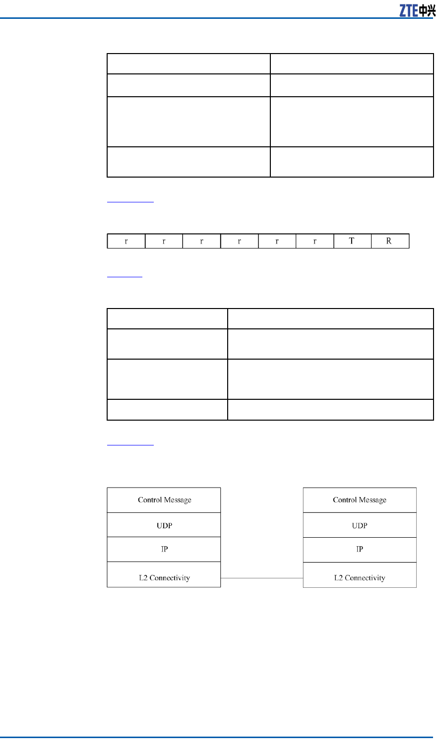
Figure12illustratesthedetailedformatoftheFlagseld.
FIGURE12FLAGSFIELDFORMAT
Table9liststheFlagseldsandtheirdescription.
TABLE9FLAGSFIELDDESCRIPTION
FieldDescription
rReservedbit,whichmustbesetto0.The
receivershouldignorethereservedbit.
TIfthisbitiscongured,themessage
shouldcontainSourceIdentierTLVand
DestinationIdentierTLV.
RResetsthenextexpectedTransactionID.
ControlPlane
ProtocolStackFigure13illustratesthestructureoftheR6controlplaneprotocol
stack.
FIGURE13R6CONTROLPLANEPROTOCOLSTACK
AlogicalconnectivitybetweenL2/L3oftwocontrolplaneprotocol
stacksenablescommunicationbetweenthetwofunctionalentities.
TheencapsulationofIPpacketsbetweenthetwofunctionalenti-
tiesreliesontheconnectivitytype,suchasGREtunnel.Theseal
oftheencapsulatedpacketcontainsaddressinformation,which
ensuresthatthepacketcanbesenttothecorrectphysicalentity.
PhysicalLayerThephysicallayeroftheR6interfacesupportspacketaccessand
TimeDivisionMultiplexing(TDM)access.
16CondentialandProprietaryInformationofZTECORPORATION

Chapter1ProductOverview
Packetaccess:10M/100M/1000MBpsFEelectricalport;1000
MBpsEthernetopticalport
CondentialandProprietaryInformationofZTECORPORATION17

ZXMBWE9230UserManual
Thispageisintentionallyblank.
18CondentialandProprietaryInformationofZTECORPORATION

Chapter2
HardwareDescription
TableofContents
CabinetStructure..............................................................19
HardwareModules.............................................................21
MTRWModule...................................................................21
WDPAModule...................................................................21
WRFEModule....................................................................22
WRPMModule...................................................................23
CabinetStructure
Figure14showsthestructureoftheZXMBWE9230cabinet.
CondentialandProprietaryInformationofZTECORPORATION19
ZXMBWE9230UserManual
FIGURE14ZXMBWE9230CABINETSTRUCTURE
Note:
DonotopentheZXMBWE9230cabinet.ContactZTEengineersto
openitformaintenance.
20CondentialandProprietaryInformationofZTECORPORATION

Chapter2HardwareDescription
HardwareModules
ZXMBWE9230mainlyconsistsoffourmodules:basebandin-
termediatefrequencyboardMTRW ,WiMAXDigitalPowerAmpli-
er(WDPA),WiMAXRFFrontEndFilter(WRFE),andWiMAXRRU
PowerModule2(WRPM2)DCpowersupplymodule.
MTRWModule
ThebasebandRFmoduleMTRWisthecoremoduleofZXMBW
E9230.TheMTRWmoduleprovidesthefollowingbasicfunctions.
1.MAClayerfunctions,includingscheduling,powercontrol,and
OMC.
2.Physicallayerfunctions,includingOFDMAmodulationandde-
modulationofbasebandsignals.
3.RFforwardchannelfunctions,includingup-converting,Digital
Predistortion(DPD)processing,andpoweramplifyingofbase-
bandsignals,aswellasenergyconversionbetweentheelectric
eldandthemagneticeld.
4.ReversefunctionsoftheRFchannel,includingreceiving,am-
plifying,anddown-convertingofRFsignals.
5.Clockprocessingfunctions,includingGPSsignalreceivingand
clockprocessing.
6.CascadingandconvergenceoftheR6daisychainsandstars
oftheactive/standbyE9230,aswellasclockcascading.
7.Management,monitoring,andmaintenancefunctionsofthe
E9230.
WDPAModule
TheWDPAmoduleampliestheRFpower .
FunctionTheWDPAmoduleprovidesthefollowingfunctions:
�RFamplication
�VoltageStandingWaveRatio(VSWR)measurement
�Alarmreporting
WorkingPrincipleFigure15showstheworkingprincipleoftheWDPAmodule.
CondentialandProprietaryInformationofZTECORPORATION21
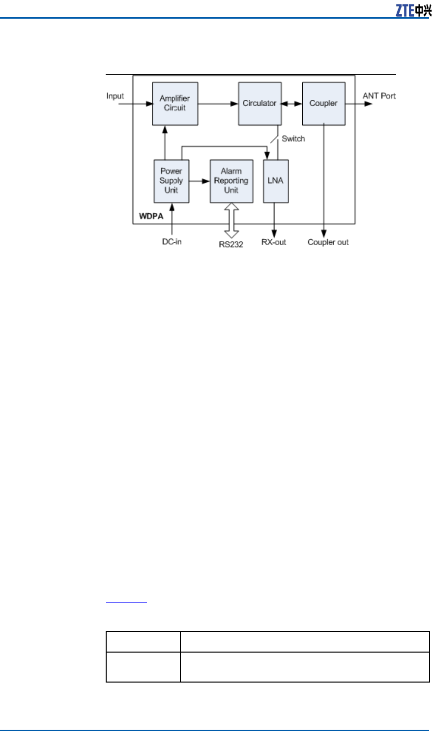
ZXMBWE9230UserManual
FIGURE15WDPAWORKINGPRINCIPLE
TheWDPAmoduleconsistsofanAmplierCircuit,Circulator ,Cou-
pler ,PowerSupplyUnit,AlarmReportingUnit,andLNA.
�AmplierCircuitprovidesthemainRFamplicationchannel.
�Circulatorseparatesthereceivingandsendingsignals.
�CouplerextractstheRFsignalstransmittedbytheBSformon-
itoringandmeasurement.
�PowerSupplyUnitprovidespowerforeachunit.
�AlarmReportingUnitreportssuchalarmsastemperature,
high/lowpowerandstandingwavealarms.
�LowNoiseAmplier(LNA)ampliesthereceivedsignals.
WRFEModule
TheWRFEmoduleistheWiMAXRFFrontEndFiltermoduleof
ZXMBWE9230.
FunctionTheWRFEmoduleprovidesthefollowingfunctions:
�ProvidestheRFinterfacetotransferRFsignalstotheantenna.
�FiltersRFsignals.
�ProvidesRFunitlightningprooffunction.
�Isolatesuplinkfromdownlink.
Performance
SpecicationsTable10liststheperformancespecicationsoftheWRFEmodule.
TABLE10WRFEPERFORMANCESPECIFICATIONS
IndexRange
Frequency
range
2496MHz~2690MHz
22CondentialandProprietaryInformationofZTECORPORATION
Chapter2HardwareDescription
WRPMModule
InZXMBWE9230,theWiMAXRRUPowerModule(WRPM)isre-
sponsibleforpowersupplyconversion.
FunctionTheWRPMmoduleprovidesthefollowingfunctions:
�Powersupplyconversion
�Lightningproof
�EMIltering
�Powersupplymanagementandalarmreporting
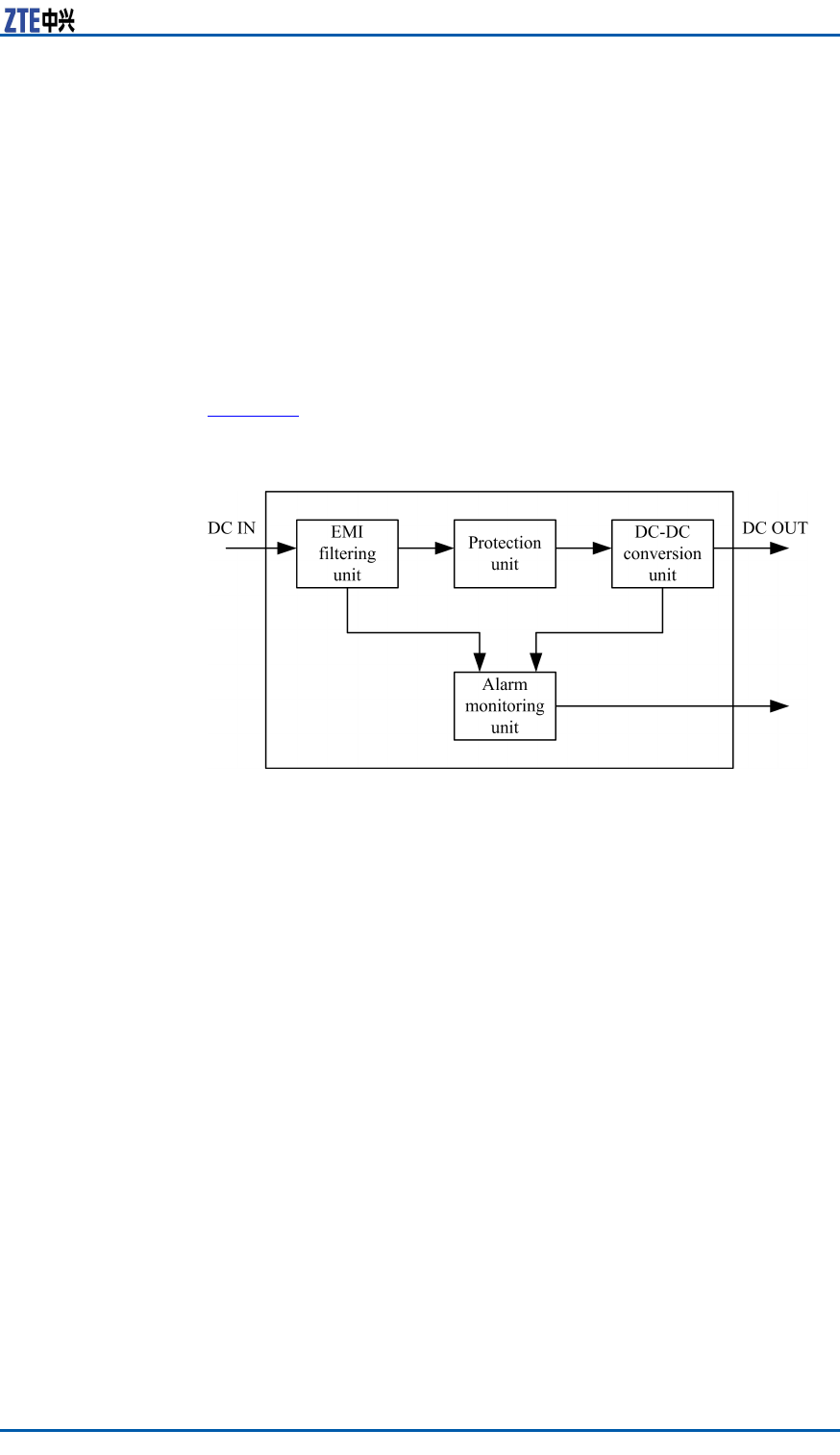
WorkingPrincipleFigure16showtheworkingprincipleoftheWRPMmodule.
FIGURE16WRPMWORKINGPRINCIPLE(DC)
TheWRPMmoduleconsistsofEMIlteringunit,protectionunit,
DC-DCconversionunit,andalarmmonitoringunit.Thefunctions
oftheunitsaredescribedasfollows:
�TheEMIlteringunitprovidesthelteringfunction.
�Theprotectionunitprovidesover-voltageorunder-voltage
protection.
�TheDC-DCconversionunitimplementspowersupplyconver-
sion.
�Thealarmmonitoringunitreportssuchalarmsasunder-volt-
age,over-voltageandover-currentalarms.
CondentialandProprietaryInformationofZTECORPORATION23

ZXMBWE9230UserManual
Thispageisintentionallyblank.
24CondentialandProprietaryInformationofZTECORPORATION

Chapter3
EquipmentInstallation
TableofContents
ComponentstobeInstalled...............................................25
InstallationFlow................................................................25
InstallationPrecautions......................................................26
InstallationPreparation......................................................27
InstallingCabinets.............................................................30
InstallingExternalCables...................................................47
CabinetInstallationCheck..................................................60
Power-on..........................................................................61
ComponentstobeInstalled
Installationcomponentsinclude:
1.ZXMBWE9230cabinet
Note:
ThecablesinsidetheZXMBWE9230cabinetandfunctionmod-
uleshavebeeninstalledbeforeshipment.
2.Externalcable
3.Mainantennafeedersystem(includingantenna,feederand
mainfeeder)
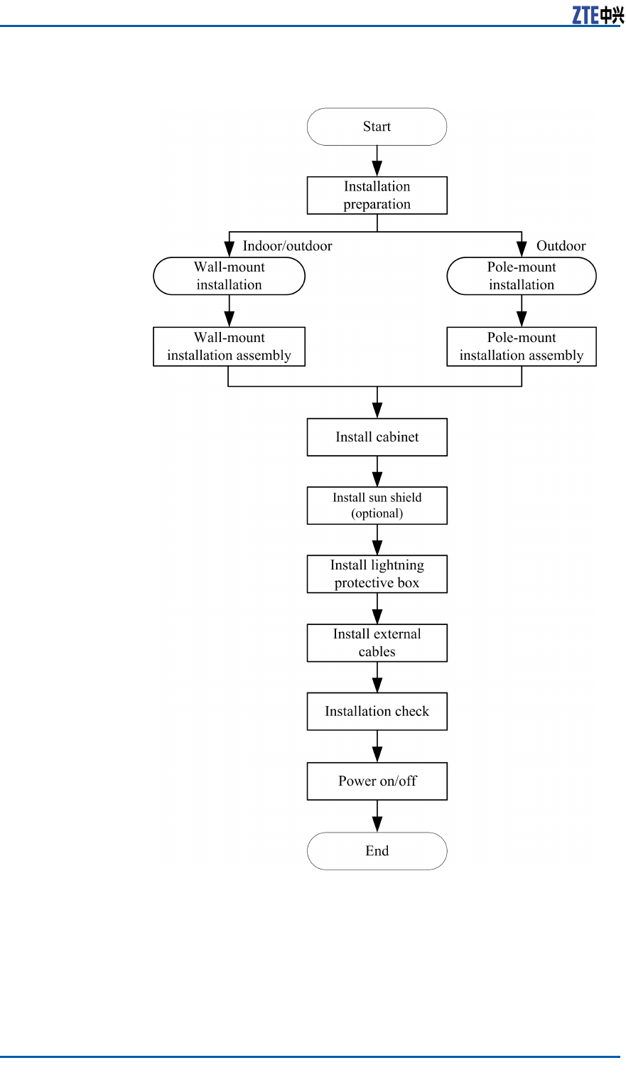
InstallationFlow
Figure17illustratestheinstallationowofZXMBWE9230.
CondentialandProprietaryInformationofZTECORPORATION25
ZXMBWE9230UserManual
FIGURE17ZXMBWE9230INSTALLATIONFLOW
InstallationPrecautions
ZXMBWE9230technicalpersonnelmustcheckequipmentrunning
environmentbeforeinstallation.Moreover ,theymustknowabout
communicationnetworking,dataconguration,statusofequip-
26CondentialandProprietaryInformationofZTECORPORATION

Chapter3EquipmentInstallation
mentinthenetwork,interfacesoflinetransmissionequipment
andlengthsofvariouscablespriortoinstallation.
Payattentiontothefollowing:
1.Avoidinstallingthecabinetinthepower-onstatus.
2.Avoidperformingoutdoorinstallationwhilelightningorthun-
derstormoccurs.
3.PerformanairtighttestbeforeRRUdelivery,andprohibitdis-
assemblingtheRRUonsite.
4.Replacinganypartsormakinganychangestotheequipment
mightresultinanunexpecteddanger .Therefore,besurenot
toreplaceanypartsorperformanychangestotheequipment
unlessauthorizedotherwise.
InstallationPreparation
InstallationEnvironmentCheck
Beforeinstallingequipment,checkinstallationenvironmentac-
cordingtoeveryitemsofrequirementsinEnvironmentAcceptance
Report.
InstallationPositionRequirements
TheinstallationpositionofZXMBWE9230mustaccordwiththe
requirementsofengineeringdesigns.Thedetailedrequirements
aredescribedasfollows.
�Locateawayfromareasthatarefullofdust,harmfulgases
andexplosivegoods.
�Locateawayfromareasthathavebigshakeorstrongnoise.
�Locateawayfromindustryboilersandheatingboilers.
�Locateawayfromaventofsmokepipe.
�Locateawayfromwaterowingareas.
�Locateawayfromhighpowerradiointerferencesource.
�Locateawayfromasubstation.
�Locateawayfrompollutionsource.
CondentialandProprietaryInformationofZTECORPORATION27

ZXMBWE9230UserManual
TemperatureandHumidity
Requirements
describestemperatureandhumidityrequirementsofZXMBW
E9230workenvironment.
TABLE11TEMPERATUREANDHUMIDITYREQUIREMENTS
ItemRequirement
Environmenttemperature-40ºC~55ºC
Storageenvironmenttemperature-45ºC~+85ºC
Environmenthumidity5%~95%
PowerSupplyRequirements
Table12describespowersupplyrequirementsofZXMBWE9230
cabinet.
TABLE12POWERSUPPLYREQUIREMENTS
CategoryRequirement
DC-36V-60VDC
Caution:
Makesurethatthepowerpolaritiesareconsistentduringinstalla-
tion;otherwise,theequipmentmaybedamaged.
OtherPreparation
1.Checkwhetherrelevantdevicesorcomponentsaccordwiththe
requirementsofengineeringdesigndrawing.
2.Wrapcableconnectorswithinsulatingtapesbeforelaying
powerandprotectiveearthingcables.
3.Separatelylayoutpowerandprotectiveearthingcablesac-
cordingtothesamesignals.
28CondentialandProprietaryInformationofZTECORPORATION

Chapter3EquipmentInstallation
ToolsandInstrumentsPreparation
Table13showstoolsandmeterslistrequiredduringinstallation.
TABLE13TOOLANDMETERLIST
CategoryName
Onefeederconnectorknife
Onewirestripper
Onecrimpingpliers
Special-purposetools
Onemulti-functionalcrimpingpliersEarth
resistancetester
Oneelectricpercussiondrill
Auxiliaryandsamplebits
Onevacuumcleaner
Concretedrillingtools
Powersocket(two-phaseandthree-phase
socket,withcurrentcapacitygreaterthan15
A)
Crossscrewdrivers(4” ,6”and8”each)
Flatheadscrewdrivers(4,6”and8”each)
Adjustablewrenches(6” ,8”,10”and12)
Dual-purposespanners(17”and19”each)
Onesetofsocketwrench
5kg(11lb)nailhammer
One300Wiron
One40Wiron
Solderwires
Hotblower
Oilpaintbrush
Pliers
Scissor
General-purposetools
Paperknife
CondentialandProprietaryInformationofZTECORPORATION29
ZXMBWE9230UserManual
CategoryName
One50m(164feet)tapemeasure
One5m(16feet)steeltape
One400mm(16inches)levelbar
Oneanglemeter
Onecompass
Measurementtools
Plumb
Antistaticwriststrap
Safetyhelmet
Protectiontools
Pairofgloves
Onehacksaw(withseveralsawblades)
Onepairofsharp-nosepliers(8″)
Onepairofdiagonalpliers(8″)
Onepairofslipjointpliers(8″)
Onepairofvices(8″)
Clamptools
Crowbar
Chainwheel
Rope
Ladder
Auxiliarytools
Forklift
InstallingCabinets
InstallationModeIntroduction
TheinstallationmodesofZXMBWE9230involvewall-mountin-
stallationandpole-mountinstallationbasedondifferentinstalla-
tionenvironments.
30CondentialandProprietaryInformationofZTECORPORATION
Chapter3EquipmentInstallation
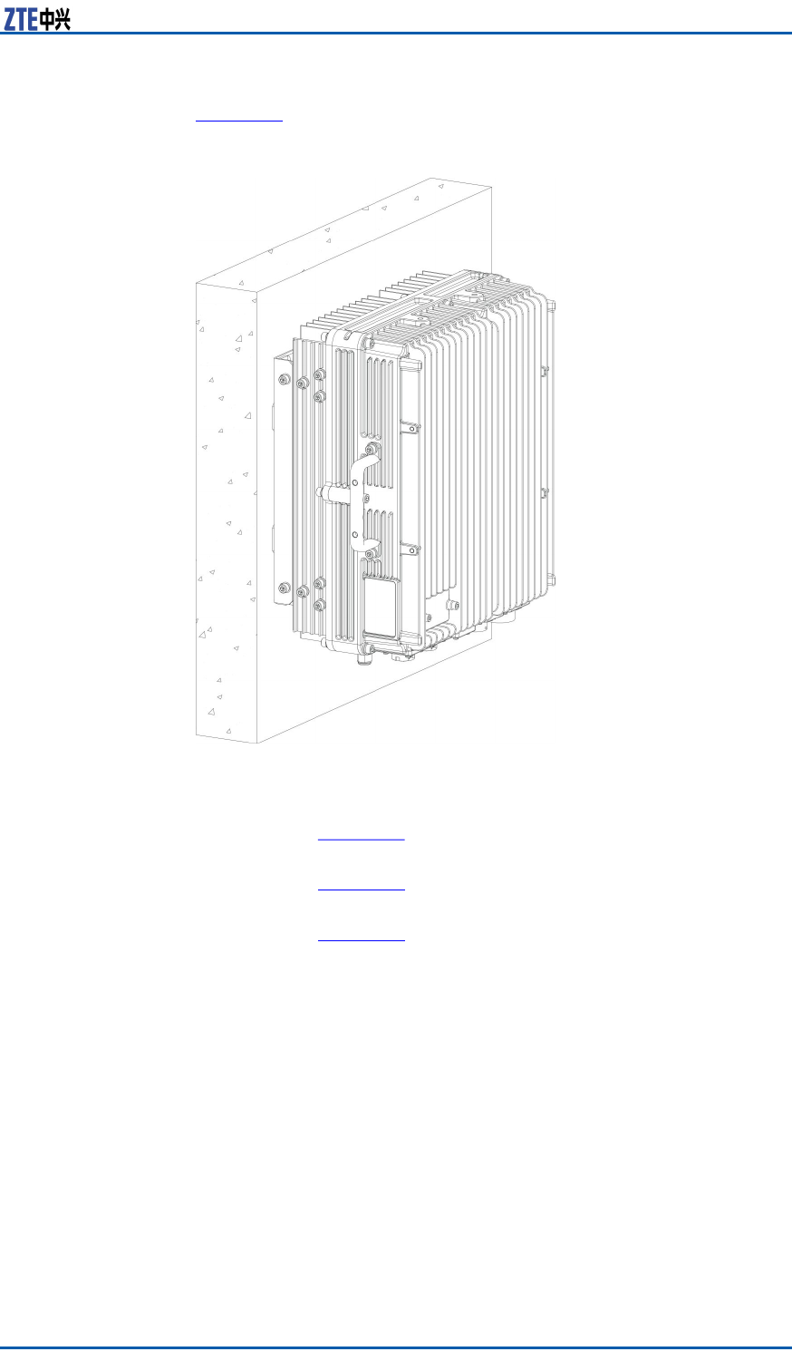
Wall-mount
InstallationFigure18illustrateswall-mountinstallation.
FIGURE18ZXMBWE9230WALL-MOUNTINSTALLATION
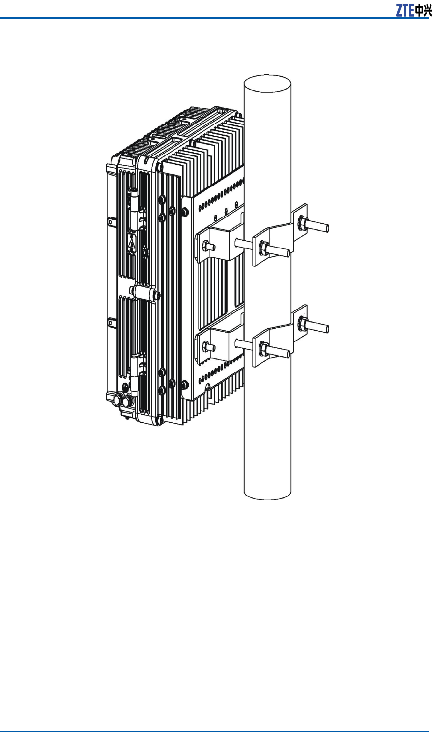
Pole-mount
InstallationThepole-mountinstallationisclassiedintothreescenarios.
1.Pole-mountinstallationwithoneZXMBWE9230cabinet,as
showninFigure19.
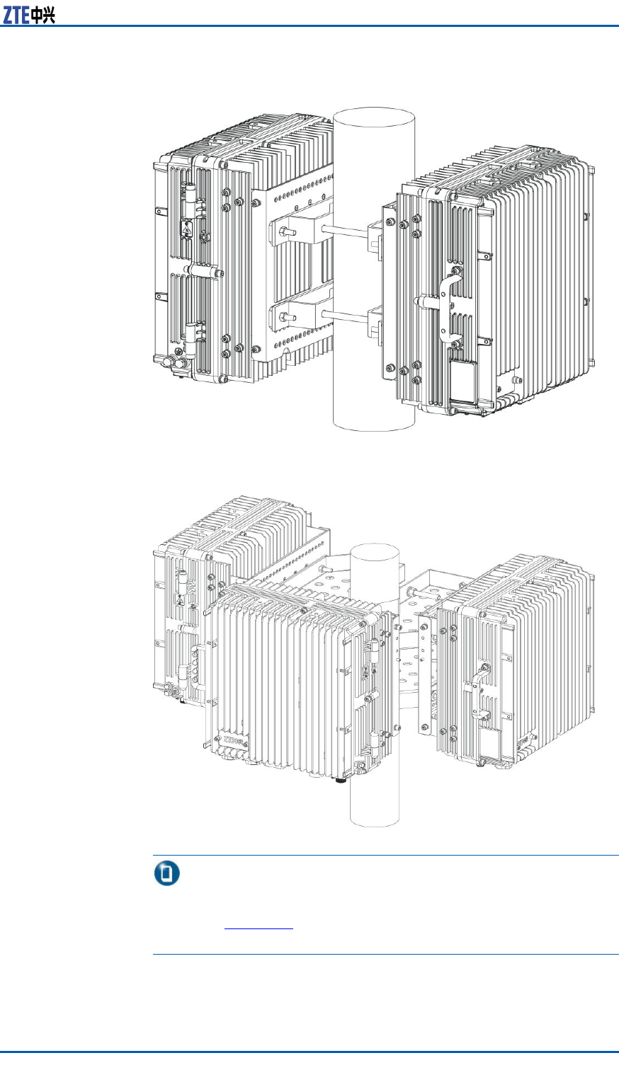
2.Pole-mountinstallationwithtwoZXMBWE9230cabinets,as
showninFigure20.
3.Pole-mountinstallationwiththreeZXMBWE9230cabinets,as
showninFigure21.
CondentialandProprietaryInformationofZTECORPORATION31
ZXMBWE9230UserManual
FIGURE19ONEZXMBWE9230POLE-MOUNTINSTALLATION
32CondentialandProprietaryInformationofZTECORPORATION
Chapter3EquipmentInstallation
FIGURE20TWOZXMBWE9230POLE-MOUNTINSTALLATION
FIGURE21THREEZXMBWE9230POLE-MOUNTINSTALLATION
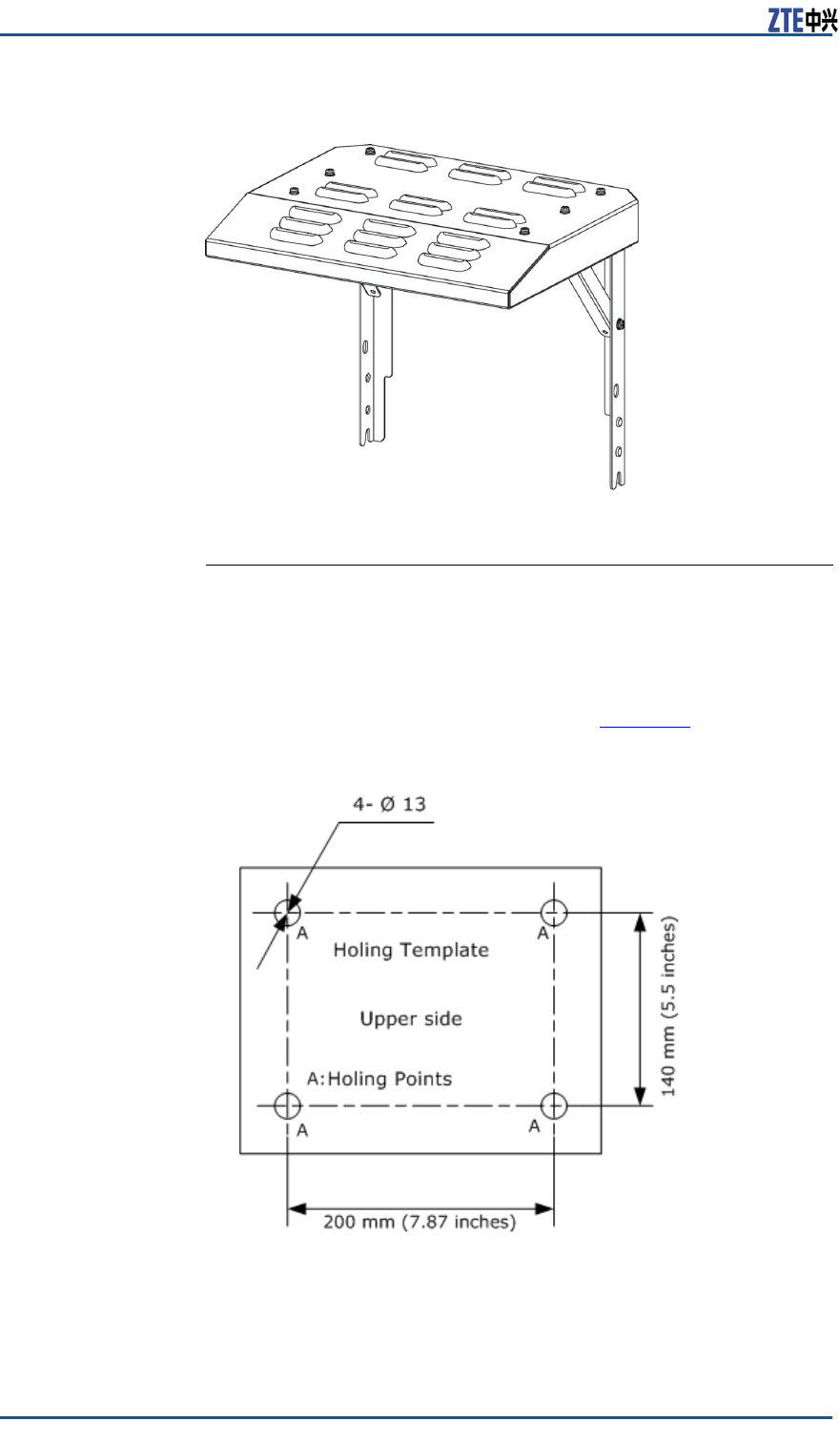
Note:
Foroutdoorinstallation,installasunshield.Thesunshieldis
showninFigure22.Forindoorinstallation,thereisnoneedto
installthesunshield.
CondentialandProprietaryInformationofZTECORPORATION33
ZXMBWE9230UserManual
FIGURE22SUNSHIELD
InstallingaWall-MountCabinet
Steps1.Markholepositions.
DeterminethepositionsonthewallforinstallingaZXMBW
E9230accordingtotheengineeringdesigndrawing.Then
marktheholepositionsonthewallwithaholedesigntem-
plate.TheholetemplateisshowninFigure23.
FIGURE23HOLINGTEMPLATE(UNITMM)
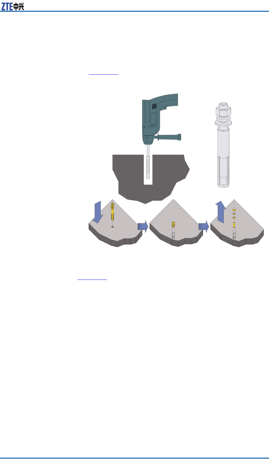
2.InstallM8×80expansionbolts.
i.Useanelectricalpercussiondrill(φ10)todrillholesatthese
positions.Useavacuumcleanertocleardustwhiledrilling.
34CondentialandProprietaryInformationofZTECORPORATION
Chapter3EquipmentInstallation
ii.Leadanexpansiontubethroughtheexpansionboltand
slightlytightenthenut.Insertthemverticallyintothehole
anduseaclawhammertostriketheexpansionboltinto
thehole.Screwdownthenuttomaketheexpansiontube
expandedenoughandthenremovethenut,asshownin
Figure24.
FIGURE24INSTALLINGM8×80EXPANSIONBOLT
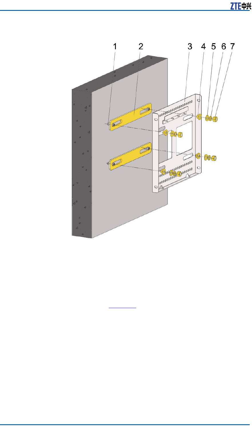
3.Installasupportingpanelonthewall.
Fixthesupportingpanelonthewallwithboltsasshownin
Figure25.
CondentialandProprietaryInformationofZTECORPORATION35
ZXMBWE9230UserManual
FIGURE25INSTALLINGSUPPORTINGPANELONWALL
1.M8×80expansionbolt
2.Insulationboard
3.Supportingpanel
4.Insulationange
5.Plainwashers
6.Springmat
7.M8nut
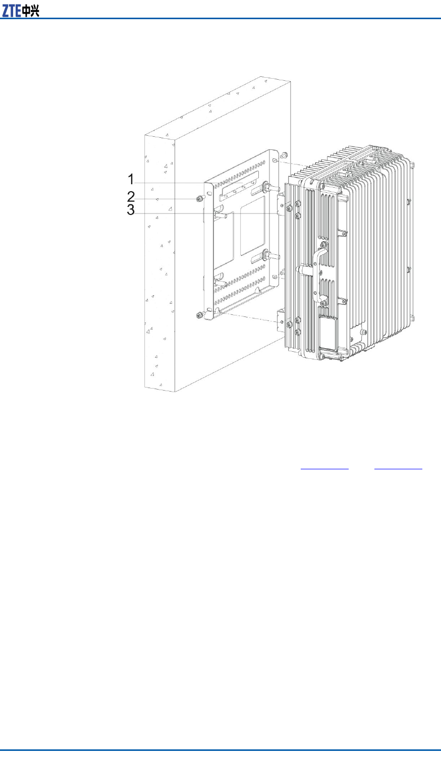
4.InstalltheZXMBWE9230cabinet.
MounttheZXMBWE9230cabinetontothesupportingpanel,
andfastenthemwithfourM6×20hexagonsocketcapscrews
asshowninFigure26.
36CondentialandProprietaryInformationofZTECORPORATION

ZXMBWE9230UserManual
FIGURE27ASSEMBLINGSUNSHIELD(1)
1.Reinforcerob
2.Bracket
3.M5×16crossrecessed
smallpanheadscrew
FIGURE28ASSEMBLINGSUNSHIELD(2)
1.M5×16crossrecessed
smallpanheadscrew
2.Sunshield
3.Reinforcerob
4.Bracket
ii.ScrewofftwoM6screwsatbothsidesofZXMBWE9230
cabinetandxthesunshieldtothesupportingpanel.
iii.MountthesunshieldtothecabinetwithtwoM6×20
hexagonscrewsandfourM5×16crossrecessedsmallpan
headcombinedscrews,asshowninFigure29.
38CondentialandProprietaryInformationofZTECORPORATION

Chapter3EquipmentInstallation
FIGURE29INSTALLINGSUNSHIELD
1.Sunshield
2.M5×16crossrecessed
smallpanheadscrew
3.Bucklingposition
4.M6×20hexagonscrew
5.ZXMBWE9230cabinet
ENDOFSTEPS
InstallingaPole-MountCabinet
Steps1.Mountsupportingcliporxingbracketassemblies.
ForinstallingoneortwoZXMBWE9230cabinets,pre-install
theclipstothepole,asshowninFigure30.
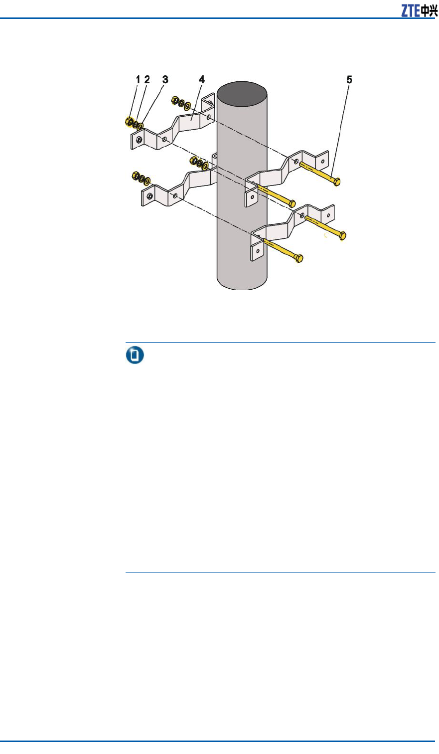
ForinstallingthreeZXMBWE9230cabinets,rstpre-installtwo
setsofxingbracketstothepole,asshowninFigure31.
CondentialandProprietaryInformationofZTECORPORATION39
ZXMBWE9230UserManual
FIGURE30MOUNTINGCLIPASSEMBLIES
1.M10nut
2.Springwasher10
3.Bigplainwasher10
4.Longclip
5.M10×120(orM10×80)
hexagonbolt
Note:
i.Thepoleshouldbemadeinthelocal.Thesuggestedpole
diameteris60to120mm(2.364.72inches).
–ForinstallingoneZXMBWE9230cabinet,itisrecom-
mendedtousethepolewith75mmdiameter .
–ForinstallingtwoorthreeZXMBWE9230cabinets,it
isrecommendedtousethepolewith100to120mm
diameter .
ii.Therearetwokindsofboltlength:80mm(3.15inches)
and120mm(4.72inches)areavailable.andboltoflength
120mm(5.12inches)forpolediameterof90mm(3.54
inches)120mm(4.72inches).
–Usetheboltoflength80mm(3.15inches)forpole
diameterof60mm(2.36inches)90mm(3.54inches).
–Usetheboltoflength120mm(5.12inches)forpole
diameterof90mm(3.54inches)120mm(4.72inches).
40CondentialandProprietaryInformationofZTECORPORATION
Chapter3EquipmentInstallation
FIGURE31MOUNTINGFIXINGBRACKETASSEMBLIES
1.Fixingbracket
2.M10×120hexagonheadbolt
3.Springwasher10
4.Plainwasher10
5.M10hexagonnut
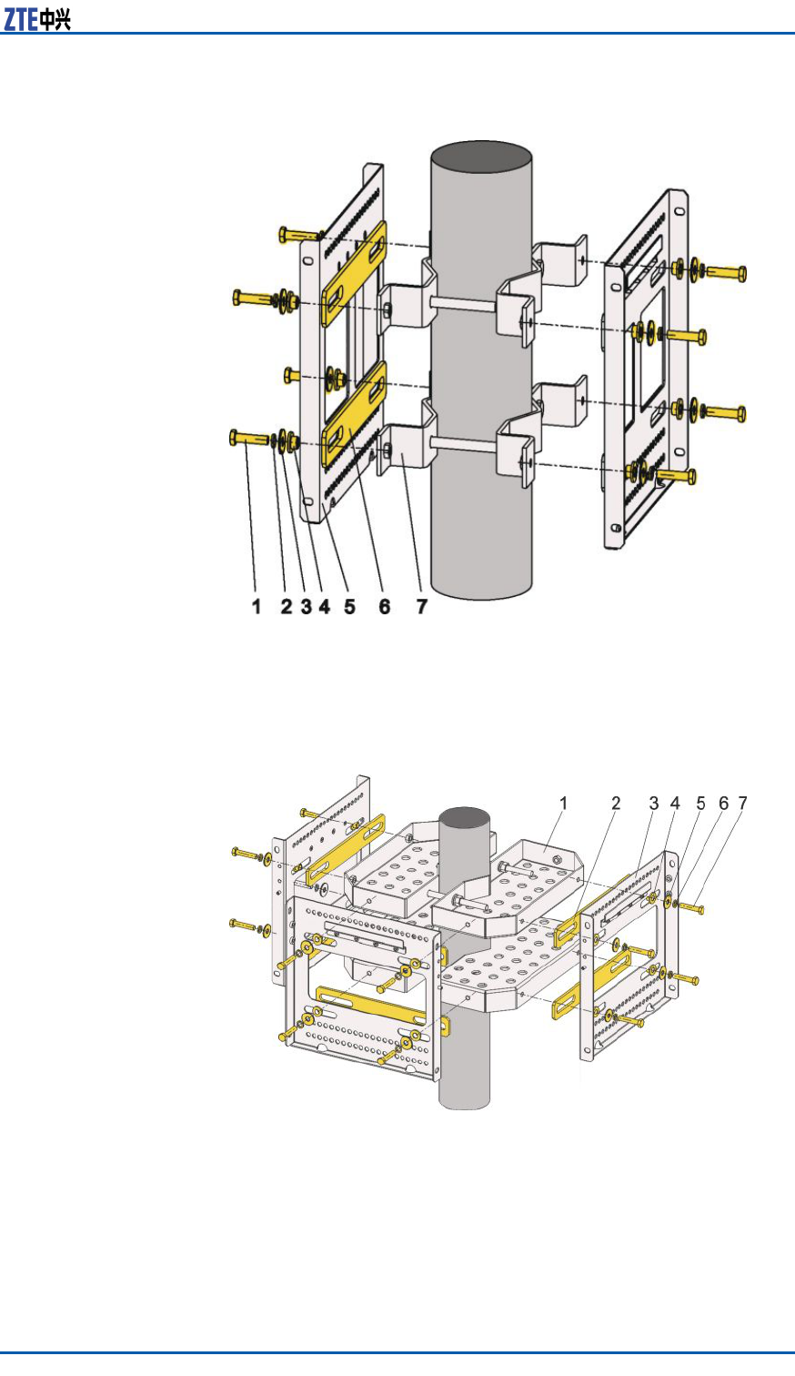
2.Mountthesupportingpanelassemblies.
ForinstallingoneZXMBWE9230cabinet,thesupportingpanel
isinstalledasshowninFigure32.
ForinstallingtwoZXMBWE9230cabinets,thesupportingpanel
isinstalledasshowninFigure33.
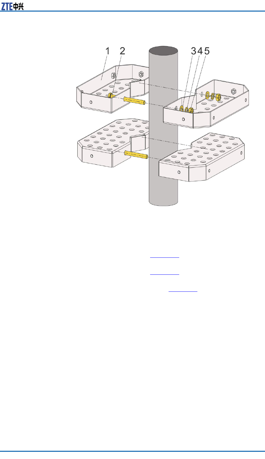
ForinstallingthreeZXMBWE9230cabinets,thesupporting
panelisinstalledasshowninFigure34.
CondentialandProprietaryInformationofZTECORPORATION41

ZXMBWE9230UserManual
FIGURE32MOUNTINGSUPPORTINGPANEL(1)
1.M8×40hexagonheadbolt
2.Springwasher8
3.Bigwasher8
4.Insulatingange
5.Supportingpanel
6.Insulatingplate
7.Longclip
8.M10×120(orM10×80)
hexagonheadbolt
9.Pole
10.Flatwasher10
11.Springwasher10
12.M8nut
13.Longclip
42CondentialandProprietaryInformationofZTECORPORATION
Chapter3EquipmentInstallation
FIGURE33MOUNTINGSUPPORTINGPANEL(2)
1.M8×40hexagonheadbolt
2.Springwasher8
3.Bigwasher8
4.Insulatingange
5.Supportingpanel
6.Insulatingplate
7.Longclip
FIGURE34MOUNTINGSUPPORTINGPANEL(3)
1.Fixingbracket
2.Insulatingplate
3.Supportingpanel
4.Insulatingange
5.Bigwasher8
6.Springwasher8
7.M8×40hexagonheadbolt
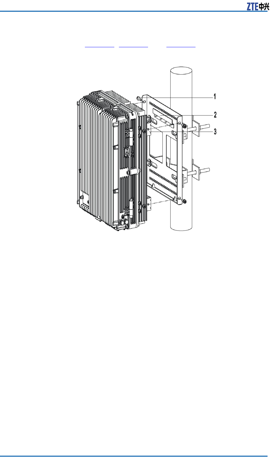
3.MounttheZXMBWE9230cabinet.
HoldtheZXMBWE9230cabinet,alignandxitsbeamtothe
correspondingblockplateonthesupportingpanel.UseM6×20
CondentialandProprietaryInformationofZTECORPORATION43
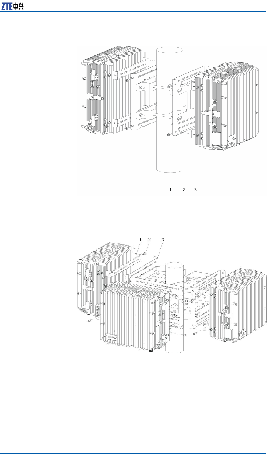
Chapter3EquipmentInstallation
FIGURE36MOUNTINGTWOZXMBWE9230CABINETS
1.M6×20hexagonheadscrew
2.Supportingpanel
3.BeamontheZXMBWE9230
cabinet
FIGURE37MOUNTINGTHREEZXMBWE9230CABINETS
1.BeamontheZXMBWE9230
cabinet
2.M6×20hexagonheadscrew
3.Supportingpanel
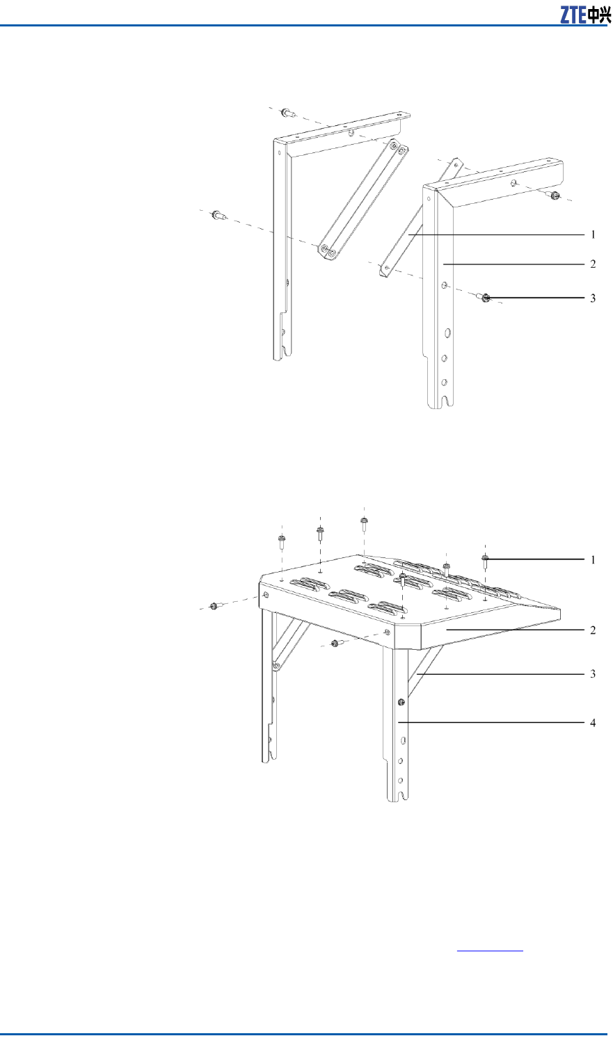
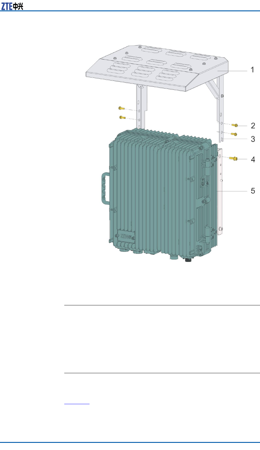
4.Installasunshield(optional).
i.AssemblethesunshieldwithM5×16crossrecessedsmall
panheadscrews,asshowninFigure38andFigure39.
CondentialandProprietaryInformationofZTECORPORATION45
ZXMBWE9230UserManual
FIGURE38ASSEMBLINGSUNSHIELD(1)
1.Reinforcerob
2.Bracket
3.M5×16crossrecessed
smallpanheadscrew
FIGURE39ASSEMBLINGSUNSHIELD(2)
1.M5×16crossrecessed
smallpanheadscrew
2.Sunshield
3.Reinforcerob
4.Bracket
ii.ScrewofftwoM6screwsatbothsidesofZXMBWE9230
cabinetandxthesunshieldtothesupportingpanel.
iii.MountthesunshieldtothecabinetwithtwoM6×20
hexagonscrewsandfourM5×16crossrecessedsmallpan
headcombinedscrews,asshowninFigure40.
46CondentialandProprietaryInformationofZTECORPORATION
Chapter3EquipmentInstallation
FIGURE40INSTALLINGSUNSHIELD
1.Sunshield
2.M5×16crossrecessed
smallpanheadscrew
3.Bucklingposition
4.M6×20hexagonscrew
5.ZXMBWE9230cabinet
ENDOFSTEPS
InstallingExternalCables
InstallingPowerCable
ContextZXMBWE9230cabinetuses-48VDCforpowersupply.
Table14describespowercableconguration.
CondentialandProprietaryInformationofZTECORPORATION47
ZXMBWE9230UserManual
TABLE14POWERCABLECONFIGURATION
CableType
Maxi-
mumUs-
ageDis-
tance
Recom-
mended
UsageDis-
tance
Note
4–coreDCpower
cable,1.5mm2
percore
80mWithin60
m
-48Vand-48GND
respectivelyusetwo
cores
2–coreDCpower
cable,6mm2per
core
150mWithin80
m
-48Vand-48GND
respectivelyuseone
core
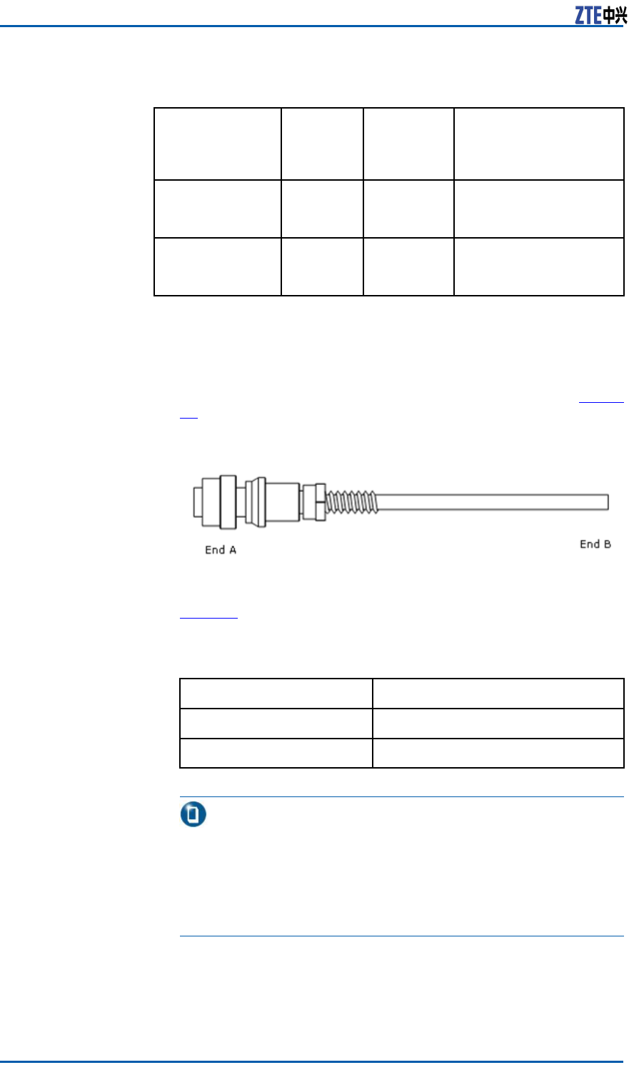
DCPowerCable
1.OneendofDCpowercableisatypeofaviationconnector
(four-core)andtheotherendisreservedforengineering.The
lengthofcablethatismadeonsiteisbasedontheengineering
survey.ThestructureofDCpowercableisasshowninFigure
41.
FIGURE41DCPOWERCABLESTRUCTURE
2.Table15describescorecoloranddenitioninsidetheDCpower
cable.
TABLE15DCPOWERCABLEINNERCORECOLORANDDEFINITION
ColorDenition
Blue-48V
Black-48VGND
Note:
i.Usingtwo-corecable,thebluecorestandsfor-48Vandthe
blackcorestandsfor-48VGND.
ii.Forfour-corecable,thetwo-linkbluecorescombinedstand
for-48Vandtwo-linkblackcorescombinedstandfor-48V
GND.
Steps1.ConnectEndAofpowercabletoapowerinterfaceofZXMBW
E9230cabinet(DCpowercableisconnectedtoDCINinter-
face).
48CondentialandProprietaryInformationofZTECORPORATION
Chapter3EquipmentInstallation
2.StripoffaprotectivesheathofEndBandconnecttorelevant
powerdevicesaccordingtothecorecolors.
3.Bindandfastenthepowercableat0.5moffthelowercon-
nector .
4.Performwaterproofprocessingfortheaviationconnector .
5.Afxalabelwithfastenersattwoendsofpowercable.
ENDOFSTEPS
InstallingGroundingCable
Prerequisites1.InstalltheZXMBWE9230cabinet.
2.Installthegroundingcopperbar .
3.Measurethegroundingresistance(≤10Ω).
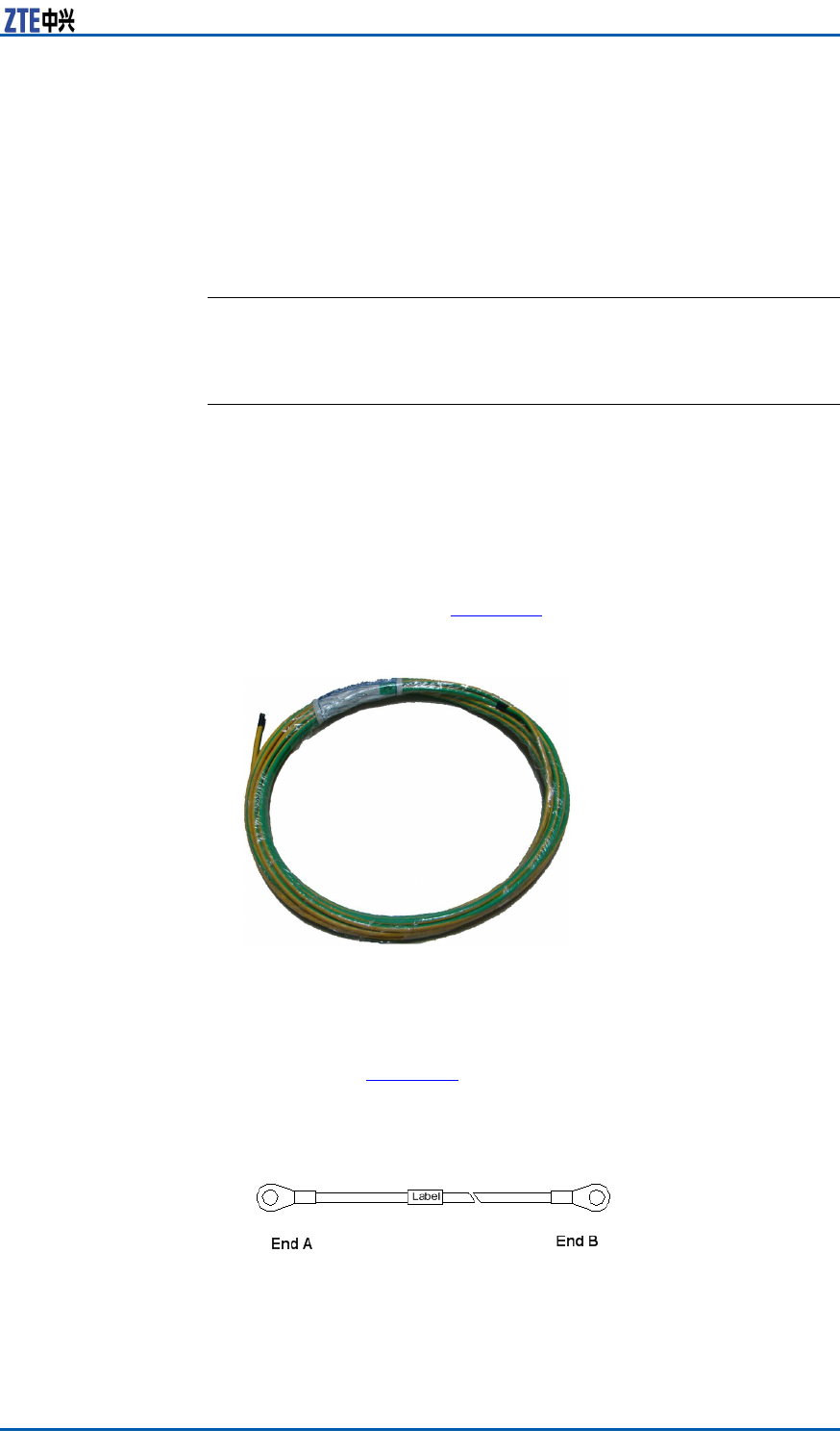
Context1.Thegroundingcableismadeofreproofmulti-strandconduc-
tors.Itisinyellowandgreenanditscrosssectionalareais
16mm2,asshowninFigure42.
FIGURE42GROUNDINGCABLE
Steps1.Copperlugsarecrimpedatbothendsofthegroundingcable,
asshowninFigure43.
FIGURE43CRIMPINGCOPPERLUGS
CondentialandProprietaryInformationofZTECORPORATION49
ZXMBWE9230UserManual
Note:
ThegroundingcablelengththatconnectstheZXMBWE9230
cabinetwiththegroundingcopperbarshouldbelessthan2
m.
2.Connectthecopperlugattheendofgroundingcabletothe
groundingscrewofZXMBWE9230cabinet.Screwdownthe
groundingscrew.
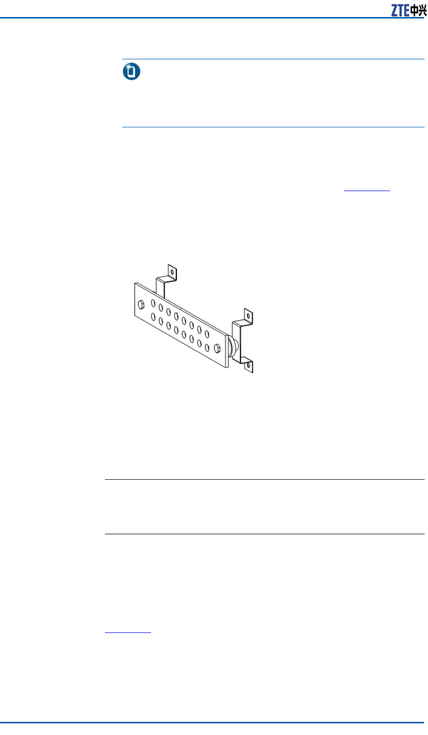
3.ThecooperbarofgroundnetisasshowninFigure44.Clear
offrustonthecopperbarandthenconnecttheotherendof
groundingcabletothecopperbar .Finally,xthemwithabolt.
FIGURE44COPPERBAROFGROUNDNET
4.Coverantirustlacqueraroundthebolt.
5.Afxalabelonthegroundingcable.
ENDOFSTEPS
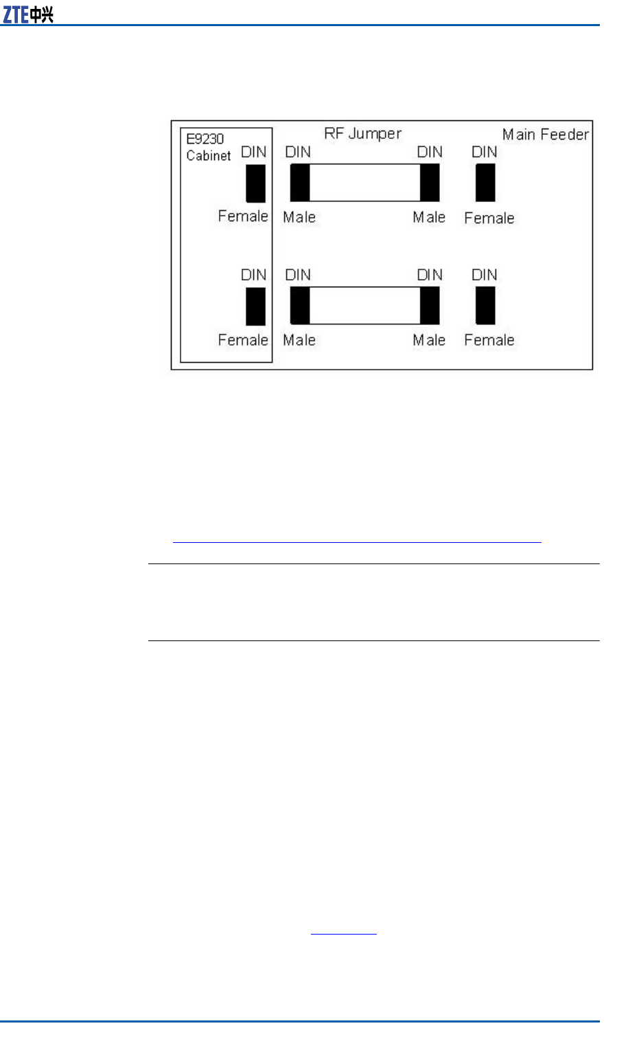
InstallingRFJumper
ContextRFjumperisusedtoconnectthemainfeederandtheantenna
feederinterfaceofZXMBWE9230.Itsinstallationissupposedto
beafterthatofthemainfeeder .
TheRFjumperadoptsthenished1/2″jumperwith2mlong.It
canalsobemadeateldworkaccordingtothepracticalcondition.
Figure45showstheinstallationpositionofRFjumper .
50CondentialandProprietaryInformationofZTECORPORATION
Chapter3EquipmentInstallation
FIGURE45RFJUMPERINSTALLATIONPOSITION
Steps1.ConnecttheDINconnector(male)oftheRFjumpertotheDIN
connector(female)ofmainfeeder .
2.ConnecttheNconnector(male)oftheRFjumpertotheRF
antennaport(port0/1)ofZXMBWE9230cabinet.
3.Performwaterproofprocessingontheconnectors,asshownin
PerformingOutdoor-connectorWaterproofProcessing.
ENDOFSTEPS
InstallingAntenna
ContextTechnicalparametersinvolvedinantennainstallation:
1.Antennaheight:Determinedbythenetworkplan.
2.Antennaazimuth:Determinedbythenetworkplan.
3.Antennapitchangle:Determinedbythenetworkplan,usually
adjustablebetween0°to10°.
4.Antennadirectionalangle:Determinedbytheantennaaz-
imuth.Thedirectionalanglesofthetwoantennasofonesector
mustbethesame.
Theantennainstallationpositionmustbeinaccordancewith
projectdesign.Iftheinstallationpositionneedsanymodication,
theprojectsupervisormustnegotiatewithoperator'srepresen-
tative.
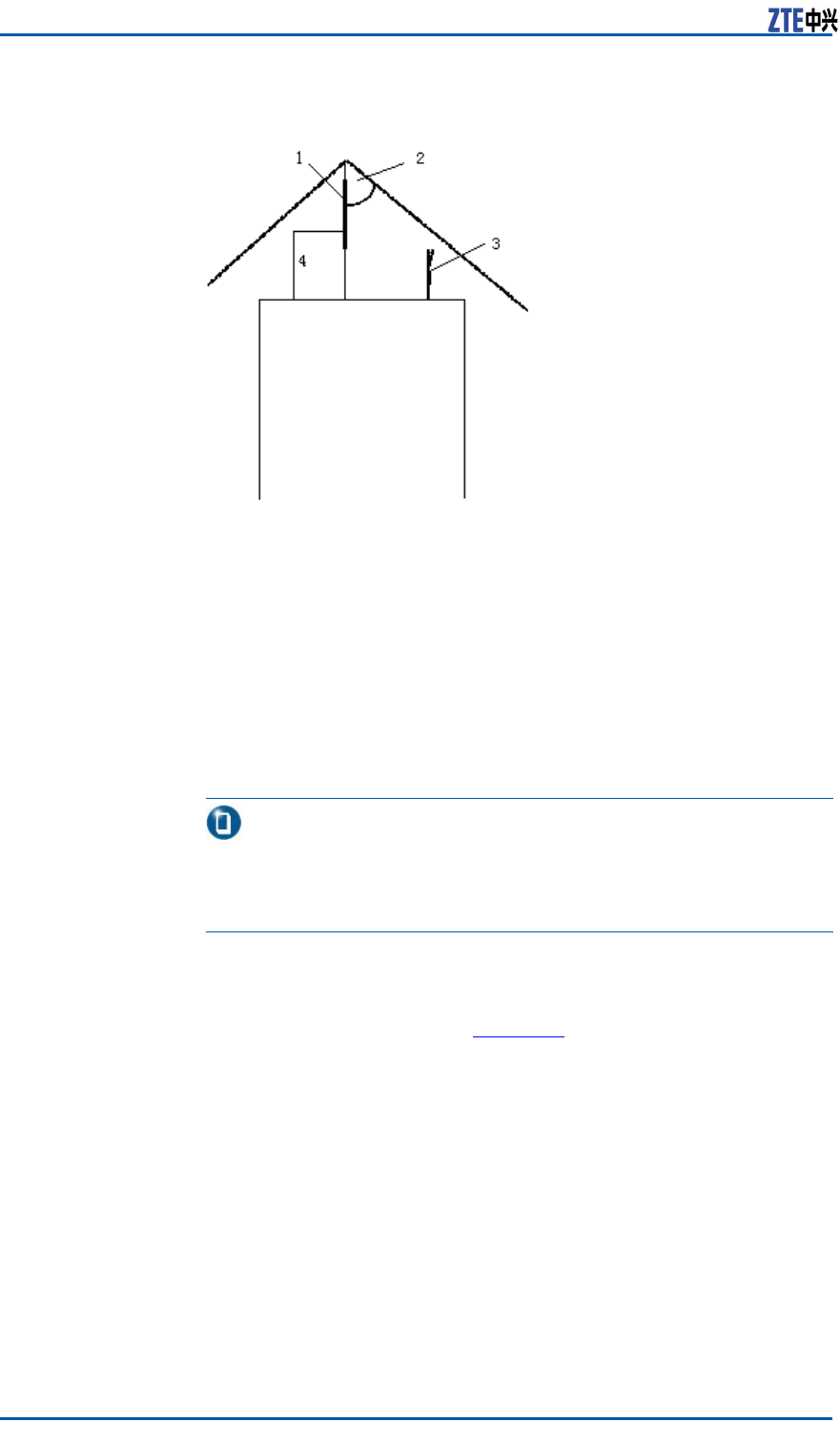
Theantennainstallationpositionneedstotakecareforelightning
protectionasshowninFigure46.
CondentialandProprietaryInformationofZTECORPORATION51
ZXMBWE9230UserManual
FIGURE46ANTENNAINSTALLATIONPOSITION
1.Lightningrod
2.45°Lightningprotectionarea
3.Antenna
4.Groundingcable
Followingarelightningprotectionrequirementstoinstallanan-
tenna:
�Theantennashouldbeinstalledwithin45°coverageareaof
lightningrod.
�Ifthereisnospeciallightningprotectionarrangementlikethe
above,installthelightningprotectionsystemontotheantenna
pole.
�Makesurethatthelightningrodiswellgrounded.
Note:
Thissectionintroducestheinstallationprocessofdirectionalan-
tennabriey.Refertotheinstallationguidedeliveredwiththe
antennafordetailedinstallationsteps.
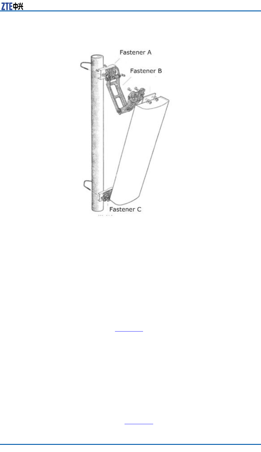
Steps1.Assemblepartsofdirectionalantenna.
Firstlyassemblefastener"C"ontotheupperandlowerends
ofantennaasshowninFigure47.Thenmountfasteners"B"
and"A"tocompletetheinitialinstallationofthedirectional
antenna.
52CondentialandProprietaryInformationofZTECORPORATION
Chapter3EquipmentInstallation
FIGURE47DIRECTIONALANTENNAINSTALLATION
2.Fixthedirectionalantennatothepole.
Attachtheantennaalongwithxturesontothepole.Donot
tightenthescrewstootightlytoalloweasyadjustmentofthe
directionanddowntiltoftheantenna.However ,degreeof
tightnessmustbeappropriateenoughtoensurethatthean-
tennadoesnotsliddownward.
3.Adjusttheantenna'sazimuth.
i.Determinetheazimuthoftheantennabyusingacompass,
anddeterminetheinstallationdirectionaccordingtothe
engineeringdesigndrawing.
ii.Turntheantennaslightlytoadjustit'sfacedirectionas
showninFigure47.Atthesametime,measurethedirec-
tionoftheantennawithacompassuntiltheerrorcomes
withintheengineeringdesignrequirements(generallynot
morethan5°).
iii.Afteradjustingtheazimuthoftheantenna,tightenthefas-
tener"A".
4.Adjusttheantenna'sdowntilt.
i.Adjustthedowntiltofthemeasurementmetertoobtain
therequiredangleaccordingtotheengineeringdesign.
ii.Turnthetopoftheantennaslightly,andlooseorfastthe
antennaatitstop.Adjustthedowntiltangleoftheantenna
tillthemeasurementmeter'sbubblecomestobecentered
asshowninFigure48.
CondentialandProprietaryInformationofZTECORPORATION53
ZXMBWE9230UserManual
FIGURE48ANTENNADOWNTILTADJUSTMENT
iii.Afteradjustingthedowntiltoftheantenna,tightenthefas-
tener"B.
ENDOFSTEPS
InstallingFeederGroundingKit
Prerequisites�Installthefeeder .
�Preparerequiredtoolsincludingpaperknife,atheadscrew-
drivers,andwrenchandsharp-nosepliers.
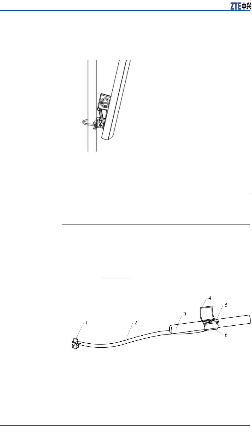
Steps1.Peeloff7/8"sheathaccordingtosizeofgroundingclipatthe
positions.Figure49illustratesstructureofgroundingkit.
FIGURE49GROUNDINGKITSTRUCTURE
1.Groundingterminal
2.Groundingcable
3.Feedercable
4.Groundingspringlock
5.Feederexternalcoppercore
6.Groundingcablecopperpiece
2.Laythegroundingcablefacingtothegroundnetwork.Avoid
bendingorfolding.Andkeeptheincludedangelbetween
groundingcableandfeedercablelessthan15°.
54CondentialandProprietaryInformationofZTECORPORATION

Chapter3EquipmentInstallation
i.Whileinstallingtheantennafeedersystemonatower ,
makesurethegroundcableofgroundingkitdownwards
alongthetower .
ii.Whileinstallingtheantennafeedersystematopabuilding,
leadthegroundcableofgroundingkittowardsalightning
net.
3.Beforeinstallingthegroundingkit,inordertoenhancesealing
effectandavoidwaterintofeederinneralongthegroundca-
ble,rstwrapwaterproofself-adhesivetaperoundtheground
cableclosetoacoppersheet,asshowninFigure50.
FIGURE50WRAPPINGWATERPROOFADHESIVETAPE
4.Clampanouterconductoroffeederwithacoppersheetof
groundcableandasnapspringandmakethecoppersheet
combinedwiththeouterconductor .
5.Performwaterproofandsealedprocessingforjunctionbetween
groundkitandfeeder .Themethodsarelistedasfollows:
i.Firstwrapwaterproofself-adhesivetapeandthenwrapPVC
adhesivetape.
ii.Forwaterproofself-adhesivetape,rstwrapfromlowerto
upperlayerbylayer ,thenwrapfromuppertolowerlayer
bylayer ,andnallywrapfromlowertoupperlayerbylayer .
Duringwrapping,theformerlayercoversahalfofthenext
layer .
6.Thegroundingterminalofgroundkitcanbeconnectedtoa
bodyoftoweroracabletrayonthetopofbuilding..While
connecting,removethepaintandoxideatconnectionplace
withinaradiusof13mm(8/16inches)aroundthejoint,and
daubtheplacewithantioxidantcreamtoensuregoodelectric
contact.Afterconnecting,paintthejointwithanticorrosive
paint.
ENDOFSTEPS
PerformingOutdoor-connector
WaterproofProcessing
ContextThewaterproofprocessingforoutdoorconnectorsadoptsthe
“1+3+3”modetowarp“onelayerPVCinsulatingtape+three
CondentialandProprietaryInformationofZTECORPORATION55

ZXMBWE9230UserManual
layerwaterproofinsulatingtape+threelayerPVCinsulating
tape”.
ThewaterproofinsulatingtapeisasshowninFigure51.
FIGURE51WATERPROOFINSULATINGTAPE
ThePVCadhesivetapeisasshowninFigure52,usedtoprotect
connectorsfromdamageaswellaswaterprooftapefromaging.
FIGURE52PVCADHESIVETAPE
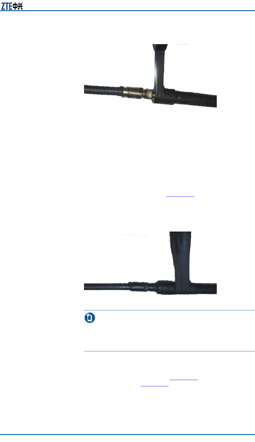
Steps1.WrapalayerofPVCinsulatingtape.
i.Cleanoutdustandstainonthefeederconnectororfeeder
groundingkit.
ii.AsshowninFigure53,wrapthefeederwiththePVCinsu-
latingtapeinanoverlappingwayfromlowertoupper ,and
theupperadhesivetapeshouldcoverahalfofthelower
adhesivetape.Theextendedwidthofadhesivetapeisnot
over1/2longerthantheformerwidth,orelseitdestroys
molecularstructureofadhesivetapeduetoextensiontoo
much.
56CondentialandProprietaryInformationofZTECORPORATION
Chapter3EquipmentInstallation
FIGURE53WRAPPINGALAYEROFPVCINSULATINGTAPE
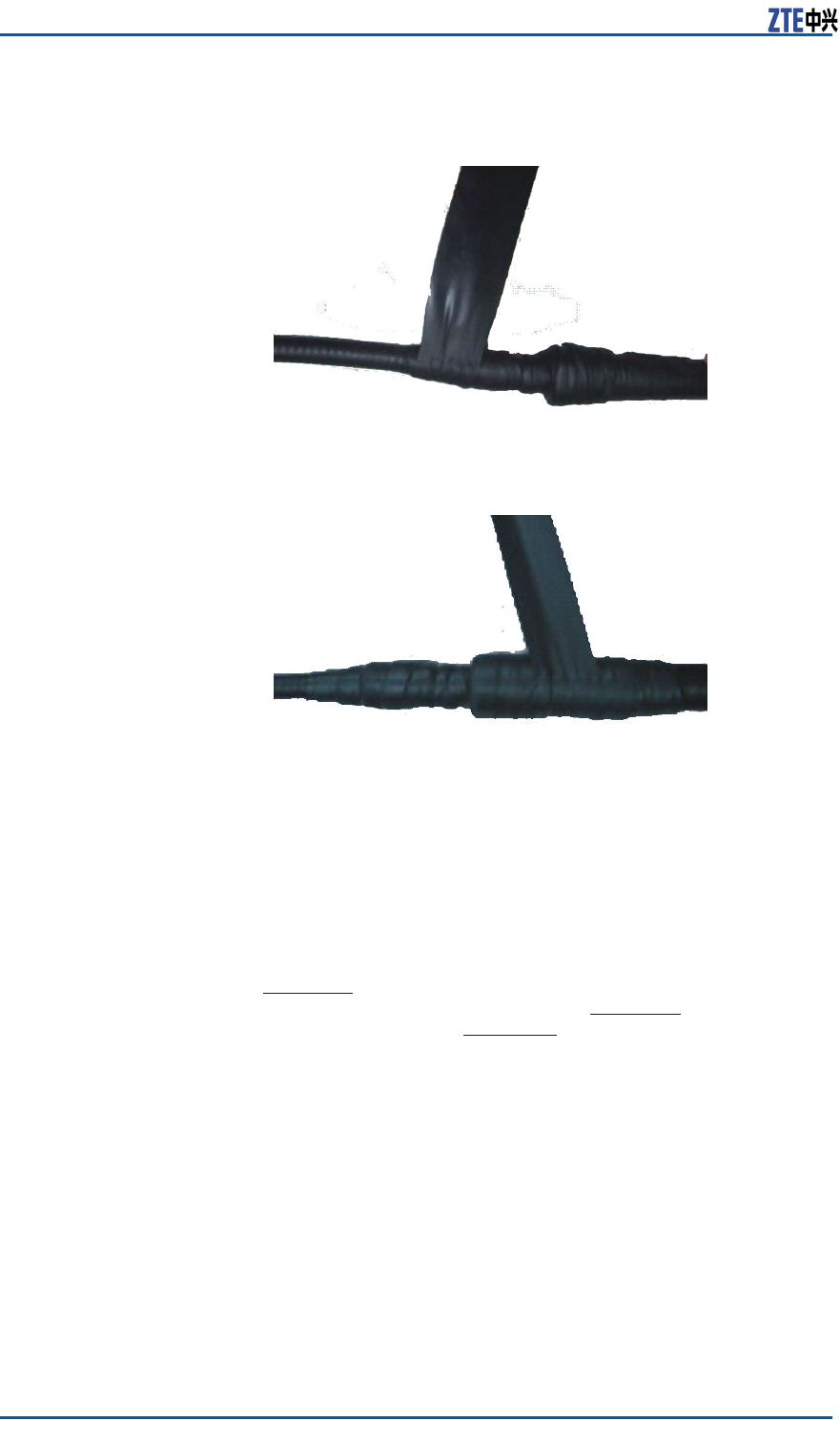
2.Wrapthreelayersofwaterproofinsulatingtape.
i.Expandthewaterproofinsulatingtapeandstripoffrelease
paper .Theadhesivetapestickstotheconnectororthe
feederwhichis20~50mmawayfromthelowerendof
groundingkit.
ii.Extendtheadhesivetapetoupto1/2–3/4oftheformer
width,inordertokeepacertainextensionstrength.Bind
thefeederinanoverlappingwayfromlowertoupper ,and
theupperadhesivetapeshouldcoverahalfofthelower
adhesivetape,asshowninFigure54.
FIGURE54WRAPPINGTHREELAYERSOFWATERINSULATINGTAPE
(THEFIRSTLAYER)
Note:
Thewrappingdirectionshouldbetowardsthedirectionof
connectorscreweddown.Prohibitwrappinginareverse
direction.
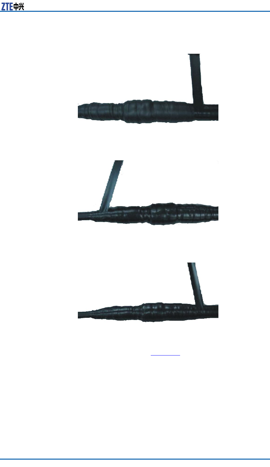
iii.Whilewrappingtothe20~50mmpositionofftheconnector
,repeatitfortwiceandthesequencerespectivelyis:from
uppertolowerasshowninFigure55andfromlowerto
upperasshowninFigure56.
CondentialandProprietaryInformationofZTECORPORATION57
ZXMBWE9230UserManual
FIGURE55WRAPPINGTHREELAYERSOFWATERINSULATINGTAPE
(THESECONDLAYER)
FIGURE56WRAPPINGTHREELAYERSOFWATERINSULATINGTAPE
(THETHIRDLAYER)
iv.Afterwrappingthewaterproofinsulatingtape,pressthe
adhesivetapeatthebindingwithhandsandmakeitafxed
tightly.
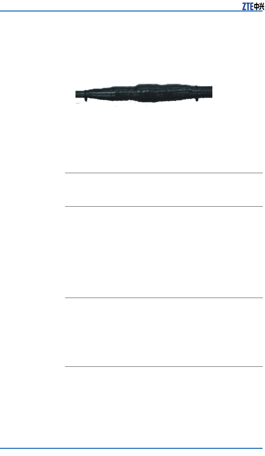
3.WrapthreelayerofPVCinsulatingtape.
TwoendsofPVCinsulatingtapemustbe20mmlongerthanthe
upperlayerofwaterproofinsulatingtape.Bindthefeederinan
overlappingwayfromlowertoupper ,andtheupperadhesive
tapeshouldcoverahalfoftheloweradhesivetape,asshown
inFigure57.Repeatitfortwiceandthesequencerespectively
is:fromuppertolowerasshowninFigure58andfromlower
toupperasshowninFigure59.Makesureproperstretch
strengthduringwrapping.
58CondentialandProprietaryInformationofZTECORPORATION
Chapter3EquipmentInstallation
FIGURE57WRAPPINGTHREELAYERSOFPVCINSULATINGTAPE(THE
FIRSTLAYER)
FIGURE58WRAPPINGTHREELAYERSOFPVCINSULATINGTAPE(THE
SECONDLAYER)
FIGURE59WRAPPINGTHREELAYERSOFPVCINSULATINGTAPE(THE
THIRDLAYER)
4.Afternishingwrapping,fastentwowrappedendswithblack
fasteners,asshowninFigure60.
CondentialandProprietaryInformationofZTECORPORATION59
ZXMBWE9230UserManual
FIGURE60FASTENING
ENDOFSTEPS
VSWRTest
Steps1.Aftertheinstallationofallantennafeedersandjumpers,con-
ducttheVSWRtest.TheVSWRmustbelessthan1.5.
2.IftheVSWRismorethan1.5,checkthemainantennaand
feedersystem,thatis:
�Checkwhethertheantennafeeders,connectors,and
jumpersareintact.
�Ensurethattheconnectionbetweenallpartsareproper .
�Checkwhethertheantennafeederinstallationisperfect.
ENDOFSTEPS
CabinetInstallationCheck
CabinetInstallationCheck
1.Ensurethatcabinetinstallationlocationcomplieswiththeen-
gineeringdesigndrawing.
2.Erectcabinetrmlysoastoresistanearthquakemeasuring
upto7.0onRichterscale.
3.Ensurethathorizontalandverticalerror ,andthegapbetween
adjacentbasesarelessthan3mm.
60CondentialandProprietaryInformationofZTECORPORATION

Chapter3EquipmentInstallation
4.Ensurethatcabinetsurfaceiscleanandtidyandcoveredwell
byoilpaint.Allpartsofthecabinetarecompletedandall
markingsonthecabinetarecorrect,clearandcomplete.
On-siteEnvironmentInspectionItems
Checkwhetherredundantgoodsonsiteareclearedoutandmake
surenobindingtape,wastecarton,wastecableandplasticbag
left.
Makesurethattheinstallationsiteisneatandtidy.
Power-on
Prerequisites1.PowersupplyvoltageaccordswithZXMBWE9230require-
ments.
2.Connectthecabinetpowerandgroundingcableproperly.
3.Thepowerswitchisdisconnected.
Steps1.ThereisnopowerswitchlocatedattheZXMBWE9230cabi-
net.Therefore,openingexternalpowerswitcheswillpoweron
ZXMBWE9230.
2.Duringpower-onprocess,ifabnormalphenomenonoccurs,
disconnectthepowerswitchimmediatelyandndthesource
ofproblem.
ENDOFSTEPS
CondentialandProprietaryInformationofZTECORPORATION61

ZXMBWE9230UserManual
Thispageisintentionallyblank.
62CondentialandProprietaryInformationofZTECORPORATION

Figures
Figure1ZXMBWE9230PositionintheNetwork......................1
Figure2ZXMBWE9230Appearance......................................3
Figure3ZXMBWE9230Composition.....................................4
Figure4ExternalInterfaces.................................................5
Figure5IndependentNetworkingApplication.........................6
Figure6ZXMBWE9230StarNetworkingApplication...............6
Figure7ZXMBWE9230DaisyNetworkingApplication..............7
Figure8ASNNetworkReferenceModel................................11
Figure9ZXMBWE9230Interfaces.......................................12
Figure10R1InterfaceProtocolStack...................................14
Figure11R6ControlPlaneMessageFormat..........................15
Figure12FlagsFieldFormat...............................................16
Figure13R6ControlPlaneProtocolStack.............................16
Figure14ZXMBWE9230CabinetStructure...........................20
Figure15WDPAWorkingPrinciple.......................................22
Figure16WRPMWorkingPrinciple(DC)................................23
Figure17ZXMBWE9230InstallationFlow............................26
Figure18ZXMBWE9230Wall-MountInstallation...................31
Figure19OneZXMBWE9230Pole-MountInstallation.............32
Figure20TwoZXMBWE9230Pole-MountInstallation.............33
Figure21ThreeZXMBWE9230Pole-MountInstallation..........33
Figure22SunShield..........................................................34
Figure23HolingTemplate(Unitmm)...................................34
Figure24InstallingM8×80ExpansionBolt............................35
Figure25InstallingSupportingPanelonWall........................36
Figure26MountingZXMBWE9230Cabinet...........................37
Figure27AssemblingSunShield(1)....................................38
Figure28AssemblingSunShield(2)....................................38
Figure29InstallingSunShield............................................39
Figure30MountingClipAssemblies.....................................40
Figure31MountingFixingBracketAssemblies.......................41
Figure32MountingSupportingPanel(1)..............................42
Figure33MountingSupportingPanel(2)..............................43
Figure34MountingSupportingPanel(3)..............................43
CondentialandProprietaryInformationofZTECORPORATION63

ZXMBWE9230UserManual
Figure35MountingOneZXMBWE9230Cabinet....................44
Figure36MountingTwoZXMBWE9230Cabinets...................45
Figure37MountingThreeZXMBWE9230Cabinets.................45
Figure38AssemblingSunShield(1)....................................46
Figure39AssemblingSunShield(2)....................................46
Figure40InstallingSunShield............................................47
Figure41DCPowerCableStructure.....................................48
Figure42GroundingCable.................................................49
Figure43CrimpingCopperLugs..........................................49
Figure44CopperBarofGroundNet.....................................50
Figure45RFJumperInstallationPosition..............................51
Figure46AntennaInstallationPosition.................................52
Figure47DirectionalAntennaInstallation.............................53
Figure48AntennaDowntiltAdjustment................................54
Figure49GroundingKitStructure........................................54
Figure50WrappingWaterproofAdhesiveTape......................55
Figure51WaterproofInsulatingT ape...................................56
Figure52PVCAdhesiveT ape..............................................56
Figure53WrappingaLayerofPVCInsulatingT ape................57
Figure54WrappingThreeLayersofWaterInsulatingT ape
(therstlayer)..................................................57
Figure55WrappingThreeLayersofWaterInsulatingT ape
(thesecondlayer).............................................58
Figure56WrappingThreeLayersofWaterInsulatingT ape
(thethirdlayer)................................................58
Figure57WrappingThreeLayersofPVCInsulatingT ape(the
rstlayer)........................................................59
Figure58WrappingThreeLayersofPVCInsulatingT ape(the
secondlayer)....................................................59
Figure59WrappingThreeLayersofPVCInsulatingT ape(the
thirdlayer).......................................................59
Figure60Fastening...........................................................60
64CondentialandProprietaryInformationofZTECORPORATION

Tables
Table1NEMeaning............................................................2
Table2ExternalInterfaceDescription...................................5
Table3EngineeringIndices..................................................7
Table4PerformanceIndices.................................................8
Table5EnvironmentalIndices..............................................9
Table6ASNInterfaceDescription........................................11
Table7R1MessageFormat.................................................13
Table8R6ControlPlaneMessageFieldDescription................15
Table9FlagsFieldDescription.............................................16
Table10WRFEPerformanceSpecications............................22
Table11TemperatureandHumidityRequirements.................28
Table12PowerSupplyRequirements...................................28
Table13ToolandMeterList................................................29
Table14PowerCableConguration......................................48
Table15DCPowerCableInnerCoreColorandDenition........48
CondentialandProprietaryInformationofZTECORPORATION65