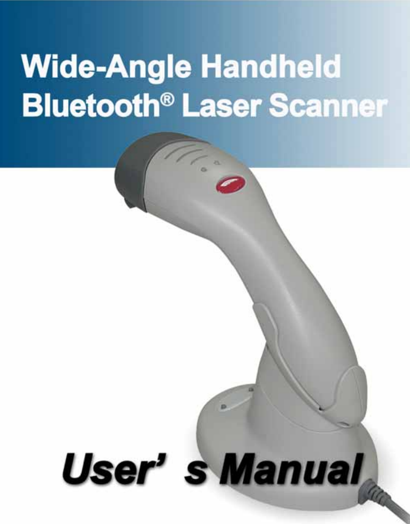
Zebex BT-CRADLE 2.4GHZ Wireless Communication Cradle User Manual User s Manual
Zebex Industries Inc 2.4GHZ Wireless Communication Cradle User s Manual
UserManual.wiki
>
Zebex
>
BT CRADLE User Manual
Users Manual
Navigation menu
Upload a User Manual
Namespaces
Wiki Guide
HTML
PDF
Info
Views
User Manual
Discussion / Help
Navigation

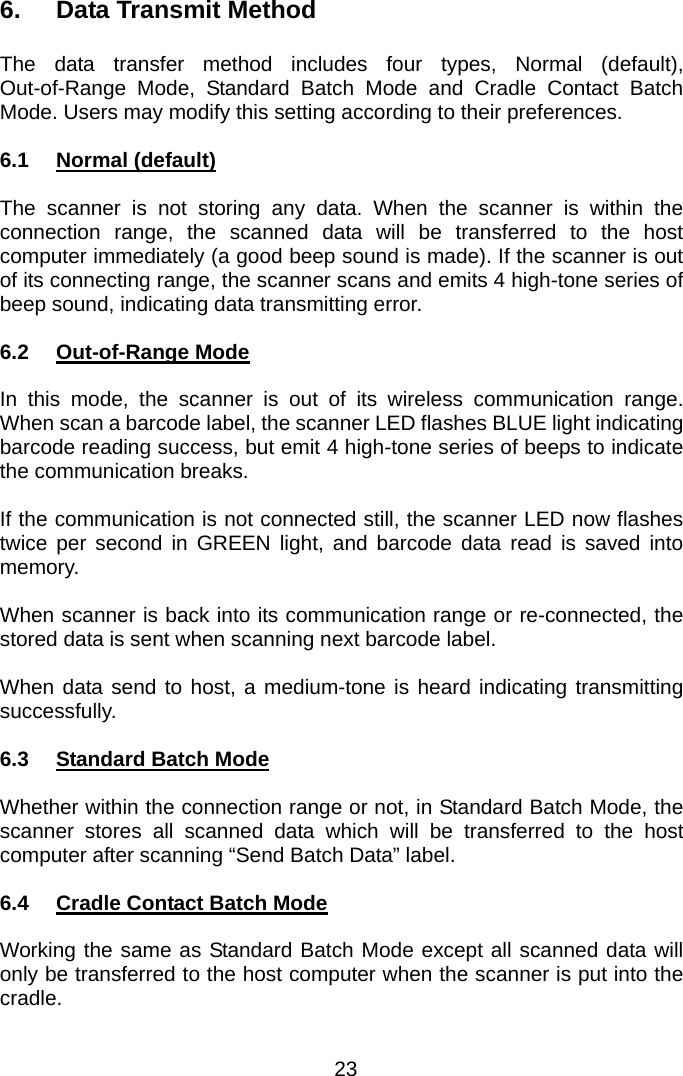
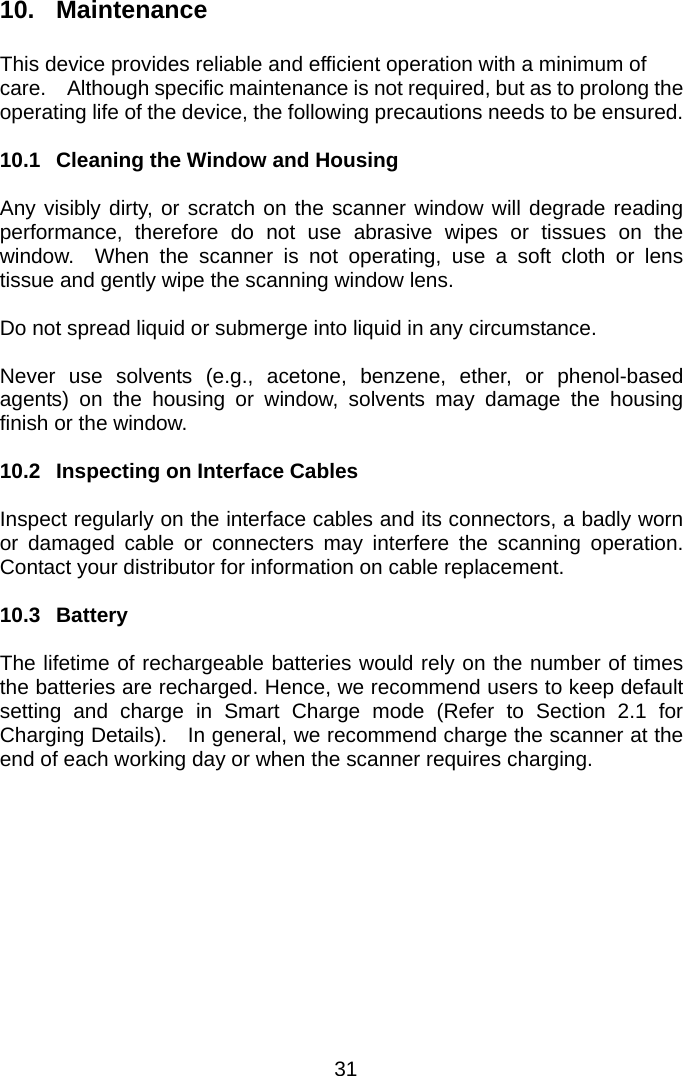
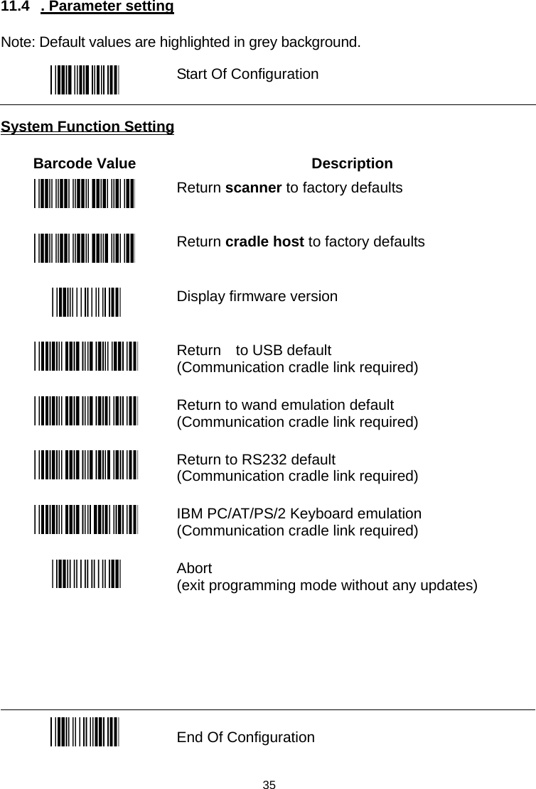
![11.2 Default Data Transmit Format Code Message format EAN-13 D1 D2 D3 D4 D5 D6 D7 D8 D9 D10 D11 D12 D13 EAN-8 D1 D2 D3 D4 D5 D6 D7 D8 UPCA D1 D2 D3 D4 D5 D6 D7 D8 D9 D10 D11 D12 UPCE D1 D2 D3 D4 D5 D6 D7 D8 CODE128 D1-Dx (default 3~62) EAN128 ]C1 D1-Dx (default 3~62) CODE39 D1-Dx (default 3~62) CODABAR D1-Dx (default 6~32) INTERLEAVED 2/5 D1-Dx (default 6~32) CHINESE POST CODE D1-Dx (default 8~32) CODE93 D1-Dx (default 3~32) MSI D1-Dx (default 6~32) 11.3 Program Procedure Using Barcode Manual Read Start of Configuration LabelSet All DefaultsSet Operating ParametersSet Serial Port ParametersSet Keyboard TypeSet Decoding ParametersFinishDiscardRead End of Configuration LabelRead Abort LabelENDSTART 34](https://usermanual.wiki/Zebex/BT-CRADLE/User-Guide-750404-Page-37.png)
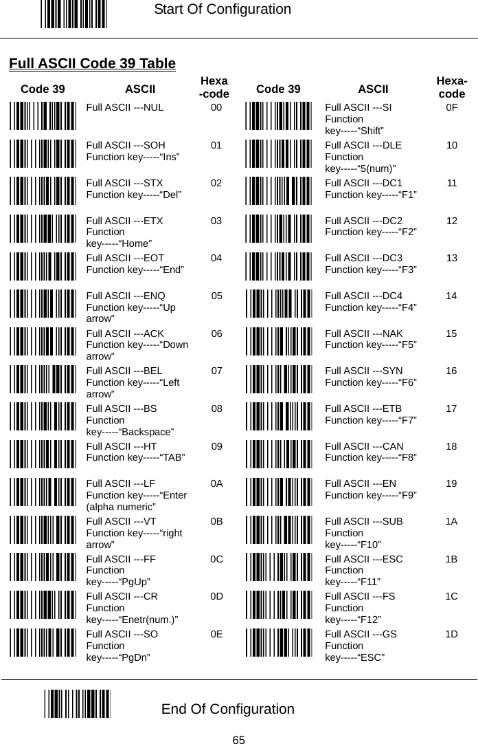
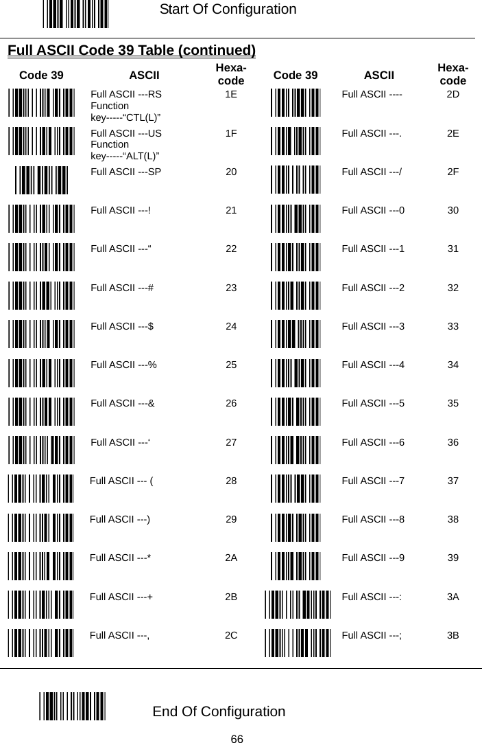
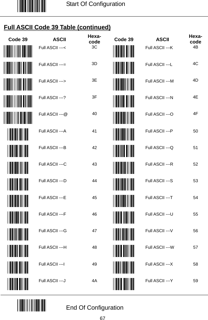
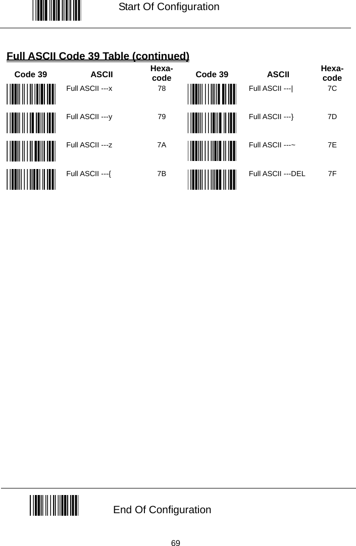
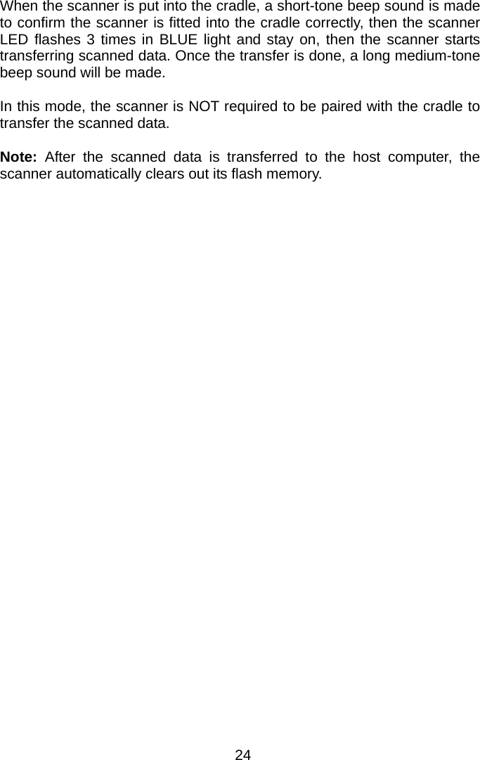
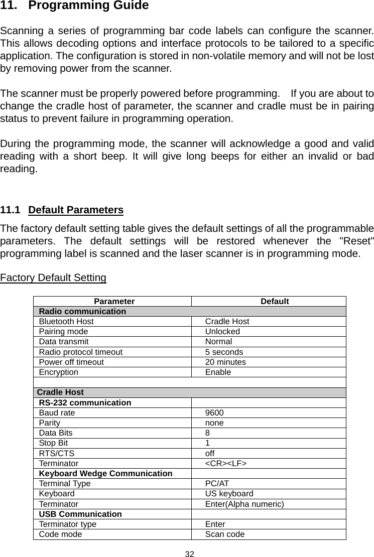
![Start Of Configuration Full ASCII Code 39 Table (continued) Code 39 ASCII Hexa-code Code 39 ASCII Hexa- code Full ASCII ---Z 5A Full ASCII ---i 69 Full ASCII ---[ 5B Full ASCII ---j 6A Full ASCII ---\ 5C Full ASCII ---k 6B Full ASCII ---] 5D Full ASCII ---l 6C Full ASCII ---^ 5E Full ASCII ---m 6D Full ASCII ---_ 5F Full ASCII ---n 6E Full ASCII ---` 60 Full ASCII ---o 6F Full ASCII ---a 61 Full ASCII ---p 70 Full ASCII ---b 62 Full ASCII ---q 71 Full ASCII ---c 63 Full ASCII ---r 72 Full ASCII ---d 64 Full ASCII ---s 73 Full ASCII ---e 65 Full ASCII ---t 74 Full ASCII ---f 66 Full ASCII ---u 75 Full ASCII ---g 67 Full ASCII ---v 76 Full ASCII ---h 68 Full ASCII ---w 77 End Of Configuration 68](https://usermanual.wiki/Zebex/BT-CRADLE/User-Guide-750404-Page-71.png)