Zebra Technologies 21121559 RFID Reader Module User Manual
Zebra Technologies Corporation RFID Reader Module
Contents
Manual
RFID Reader Module
21-121559-01 and 21-121560-01
Integration Guide (For Motorola Internal Use Only)

RFID Reader Module
21-121559-01 and 21-121560-01
Integration Guide
72E-121701-01
Rev A
April 2009

ii RFID Reader Module, Integration Guide
© 2009 by Motorola, Inc. All rights reserved.
No part of this publication may be reproduced or used in any form, or by any electrical or mechanical means,
without permission in writing from Motorola. This includes electronic or mechanical means, such as
photocopying, recording, or information storage and retrieval systems. The material in this manual is subject to
change without notice.
The software is provided strictly on an “as is” basis. All software, including firmware, furnished to the user is on
a licensed basis. Motorola grants to the user a non-transferable and non-exclusive license to use each
software or firmware program delivered hereunder (licensed program). Except as noted below, such license
may not be assigned, sublicensed, or otherwise transferred by the user without prior written consent of
Motorola. No right to copy a licensed program in whole or in part is granted, except as permitted under
copyright law. The user shall not modify, merge, or incorporate any form or portion of a licensed program with
other program material, create a derivative work from a licensed program, or use a licensed program in a
network without written permission from Motorola. The user agrees to maintain Motorola’s copyright notice on
the licensed programs delivered hereunder, and to include the same on any authorized copies it makes, in
whole or in part. The user agrees not to decompile, disassemble, decode, or reverse engineer any licensed
program delivered to the user or any portion thereof.
Motorola reserves the right to make changes to any software or product to improve reliability, function, or
design.
Motorola does not assume any product liability arising out of, or in connection with, the application or use of
any product, circuit, or application described herein.
No license is granted, either expressly or by implication, estoppel, or otherwise under any Motorola, Inc.,
intellectual property rights. An implied license only exists for equipment, circuits, and subsystems contained in
Motorola products.
MOTOROLA and the Stylized M Logo and Symbol and the Symbol logo are registered in the US Patent &
Trademark Office. Bluetooth is a registered trademark of Bluetooth SIG. Microsoft, Windows and ActiveSync
are either registered trademarks or trademarks of Microsoft Corporation. All other product or service names
are the property of their respective owners.
Motorola, Inc.
One Motorola Plaza
Holtsville, New York 11742-1300
http://www.motorola.com
Patents
This product is covered by one or more of the patents listed on the web site: http://www.symbol.com/patents

iii
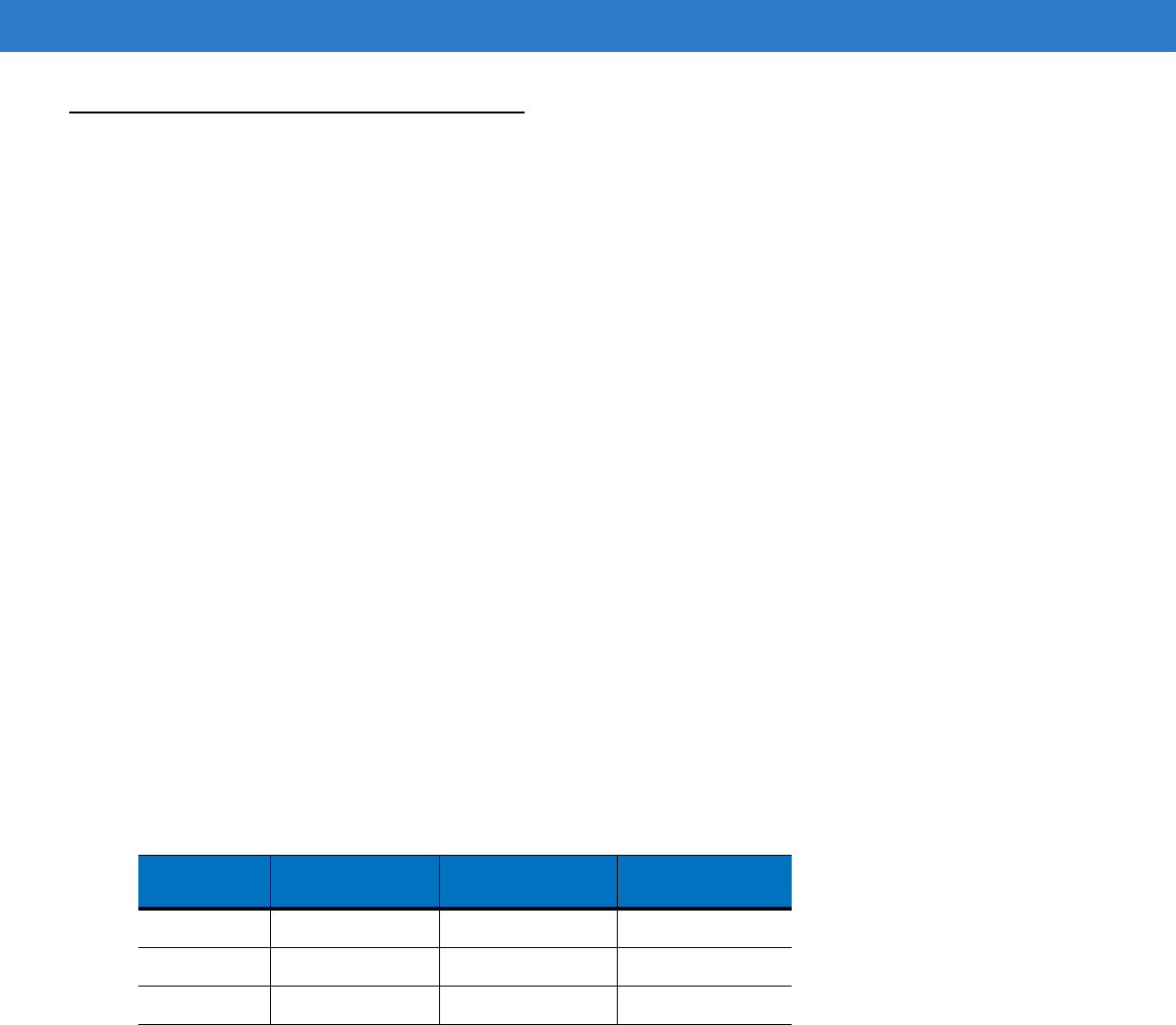
Revision History
Changes to the original manual are listed below:
Change Date Description
-01 Rev A 4/2009 Initial Release

iv RFID Reader Module, Integration Guide

Table of Contents
Patents.................................................................................................................................................. ii
Revision History.................................................................................................................................... iii
About This Guide
Introduction ........................................................................................................................................... vii
Documentation Set ......................................................................................................................... vii
Configurations....................................................................................................................................... vii
Chapter Descriptions ............................................................................................................................ vii
Notational Conventions......................................................................................................................... viii
Service Information............................................................................................................................... viii
Support Information ........................................................................................................................ viii
Chapter 1: Introduction
Introduction .......................................................................................................................................... 1-1
Sailfish Integration ............................................................................................................................... 1-2
Unpacking the Reader Module ............................................................................................................ 1-3
Connections and Ports ........................................................................................................................ 1-3
Theory of Operation ............................................................................................................................. 1-4
Block Diagram ................................................................................................................................ 1-4
Receive Path ............................................................................................................................ 1-5
Transmit Path ........................................................................................................................... 1-5
Microprocessor Control ............................................................................................................ 1-5
Frequency Generation ............................................................................................................. 1-5
Chapter 2: Installation
Overview .............................................................................................................................................. 2-1
Mounting Considerations ..................................................................................................................... 2-1
Environment ................................................................................................................................... 2-1
Grounding ...................................................................................................................................... 2-1
ESD ................................................................................................................................................ 2-1
Location and Positioning ...................................................................................................................... 2-2
Using the RFID Reader Module ..................................................................................................... 2-2

vi RFID Reader Module, Integration Guide
External Hardware Interfaces .............................................................................................................. 2-2
Antenna Interface ........................................................................................................................... 2-2
Thermal Interface ........................................................................................................................... 2-3
Host Interface ................................................................................................................................. 2-4
Module Control Signals .................................................................................................................. 2-5
Mechanical Characteristics .................................................................................................................. 2-6
Enclosure and EMI Shielding ......................................................................................................... 2-6
Thermal Management .................................................................................................................... 2-6
Mounting ........................................................................................................................................ 2-6
Environmental Characteristics ............................................................................................................. 2-8
Thermal Management .................................................................................................................... 2-8
Read/Write Ranges ............................................................................................................................. 2-8
Appendix A: Technical Specifications
Technical Specifications ...................................................................................................................... A-1
RFID Reader Module ..................................................................................................................... A-1
Reference Performance Characteristics .............................................................................................. A-7
Link Profiles and XRM ......................................................................................................................... A-8
Appendix B: Timing
Power Up and Reset Timing ................................................................................................................ B-1
Appendix C: Regulatory Requirements
User Guide Statements ....................................................................................................................... C-1
General Statements ....................................................................................................................... C-1
FCC Statements ............................................................................................................................ C-1
Industry Canada Statements ......................................................................................................... C-2
European Statements .................................................................................................................... C-3
Regulatory Requirements .................................................................................................................... C-3
Legal Disclaimer ............................................................................................................................ C-3
Final Product Compliance .............................................................................................................. C-3
Reference Antenna ........................................................................................................................ C-4
Regulatory Standards .................................................................................................................... C-5
Regulatory Approvals ..................................................................................................................... C-5
Radio Card Regulatory Markings ................................................................................................... C-5
National Country Requirements ..................................................................................................... C-5
United States of America ......................................................................................................... C-5
Canada .................................................................................................................................... C-6
European Union ....................................................................................................................... C-7
Index

About This Guide
Introduction
This guide provides information about configuring and installing the RFID Reader Module into a final product.
Documentation Set
This document for the RFID Reader Module provides information for the integrator.
Configurations
This guide covers the following configurations:
Chapter Descriptions
Topics covered in this guide are as follows:
•
Chapter 1, Introduction, provides information on the RFID Reader Module.
•
Chapter 2, Installation, provides information on configuring and installing the RFID Reader Module.
•
Appendix A, Technical Specifications, includes the technical specifications for the RFID reader
•
Appendix B, Timing, provides the RFID Reader Module timing diagrams.
•
Appendix C, Regulatory Requirements, provides the RFID Reader Module regulatory requirements.
Configuration
US RFID Reader Module 21-121559-01
EU RFID Reader Module 21-121560-01

viii RFID Reader Module, Integration Guide
Notational Conventions
The following conventions are used in this document:
•
“RFID Reader”, “reader” or “reader module” refers to the Motorola RFID Reader Module.
•
Italics are used to highlight the following:
•Chapters and sections in this guide
•Related documents and links
•
Bold text is used to highlight the following:
•Dialog box, window and screen names
•Drop-down list and list box names
•Check box and radio button names
•Icons on a screen
•Key names on a keypad
•Button names on a screen.
•
Bullets (•) indicate:
•Action items
•Lists of alternatives
•Lists of required steps that are not necessarily sequential.
•
Sequential lists (e.g., those that describe step-by-step procedures) appear as numbered lists.
Service Information
If an equipment problem occurs, contact the appropriate regional Support Center for contact information. Before
calling, locate the model number and serial number.
Call the Support Center from a phone near the equipment so that the service person can try to talk through the
problem.
If the problem cannot be solved over the phone, the equipment may need to be returned for servicing. If that is
necessary, specific directions will be provided.
Support Information
For service information, warranty information or technical assistance contact or call the Support Center. Contact
information is provided on the Motorola contact web site go to: http://support.symbol.com.
If the Motorola product was purchased from a Motorola Business Partner, contact that Business Partner for
service.
NOTE Motorola is not responsible for any damages incurred during shipment if the approved shipping container
is not used. Shipping the units improperly can possibly void the warranty.

Chapter 1 Introduction
Introduction
This chapter provides an overview of the RFID Reader Module. Product specifications are provided in Table A-1 on
page A-1.
The module is a RFID Reader Engine module that supports EPC Gen2 protocol in the UHF frequency band. There
are two versions of the module:
•
10 mWatt to 1 Watt US (part No. 21-121559-01)
•
10 mWatt to 1 Watt EU (part No. 21-121560-01)
The differences between the US and EU module are Pre-PA Saw Filter and PA matching components and OEM
F/W settings.
The RFID Reader Module is based on the Intel R1000 reference design and has been modified for power efficiency
and size.
The RFID Reader Module is a RFID Radio Engine which supports ISO 18000-6C and Electronic Product Code
(EPC) Gen2 reader applications. RFID Reader Module is intended to enable Mobile Computers and Barcode
Scanners to read EPC Gen2 UHF RFID tags. The RFID Reader Module is a very small form-factor RFID Reader
engine, that when used with a high performance RFID antenna(s), can be commanded to perform EPC Gen2 RFID
Reader operations.
This document defines the RFID Reader Module functional characteristics (electrical, mechanical) and provides
information required by the system integrators to embed the RFID Reader Module in a variety of systems. A
section outlining good design practices is also incorporated to help with the overall integration of the device.
The RFID Reader Module supports all EPC Gen2 Link Profiles of the R1000 Reference Design. The RFID Reader
Module is a EPC Gen2 Compliant Mono-static Reader Module that operates in the 902MHz-928MHz ISM band in
US and Canada, and 865.6MHz - 867.6 MHz in Europe. For details see Technical Specifications on page A-1
The RFID Reader Module reference performance specifications are provided in Appendix A, Technical
Specifications on page A-7.

1 - 2 RFID Reader Module, Integration Guide
Sailfish Integration
In the early stages of Sailfish integration, the integrators need focus on key design areas to achieve the best RFID
reader performance. Some key areas that should be focused on are:
1. The power supply capacity must be sufficient for the power requirements at the targeted RF power levels.
Be sure to account for:
•
Voltage drops from your 5V supply to the Sailfish Module inputs
•
The 5V supply must stay within the range of 5V +/- 5% at the Sailfish host connector after all of the voltage
drops of battery impedances, connector contacts, flex cables, pc traces etc. The max currents of the module
are specified at 5.0V.
•
Sailfish creates very long pulses (up to 400ms) of current peaks. These current surges (that Sailfish requires)
must not create a low battery event in the power micro circuit.
2. RFID Antenna
•
The read performance of the Sailfish Module depends on not only the gain of the antenna but more
importantly the Return Loss or VSWR of the antenna across the entire bandwidth of the radio (unlike 802.11
or Bluetooth). The radio must receive a tag response while it is transmitting, and the more signal that is
reflected back from the antenna, the more blinded the receiver becomes. Also, RFID tags are not always
polarized the same way as the antenna and a robust antenna design could greatly improve read
performance. Antenna performance depends on the application requirements but must also meet the
requirements stated in Appendix C, Regulatory Requirements.
•
The antenna features that must be emphasized are bandwidth, return loss, and gain. If the return loss can
be optimized over the entire bandwidth of the radio, the radio will accomplish its reading of the tag population
in the least amount of time and for the least amount of battery power.
•
With a Motorola designed application, the Sailfish Module can be used to evaluate the VSWR or return loss
characteristic of the embedded antenna system for WinCE products. This application is called RFID Demo
and is demonstration software which can exercise the sailfish module for various test purposes.
3. Thermal Management
•
Since Sailfish has been packaged in a very small form factor, thermal management is critical during the
integration phase of this module. The Module has been designed to expose the hottest points of the module
to a cold-plate or heat-sink through thermal interface material. Proper heat sinking significantly increases the
time that the radio can operate without entering a thermal back-off mode. Once in this mode, the radio
continues to operate, but at reduced duty cycle and read rates.
•
Most applications will use some initial duty-cycle (such as 50%) for power management reasons, however
this should be considered on an individual application basis.
4. Flex Cable interface
•
The host interface is a 16 pin flex. Use heavy traces for the VCC and ground traces and it is recommended
that an outer ground plane is used to shield the control signals from system noise and ESD. The flex should
be kept as short as possible in order to reduce voltage drops to the module.
•
Once the module and corresponding host connector have been located, it is important to confirm that the
signals have not been crossed at the flex connection. This is a common error and should be considered as
part of an required design check.
Introduction 1 - 3
Unpacking the Reader Module
Carefully remove all protective material from around the reader and save the shipping container for later use.
Verify that all equipment was received:
•
RFID Reader Module
Inspect the equipment for damage. If any equipment is missing or if any equipment is damaged, contact the
Motorola Technologies Support Center immediately. See Service Information on page viii for contact information.
Note: Observe ESD precautions. Exercise care when handling the module. Use grounding wrist straps and handle
in a properly grounded work area. for
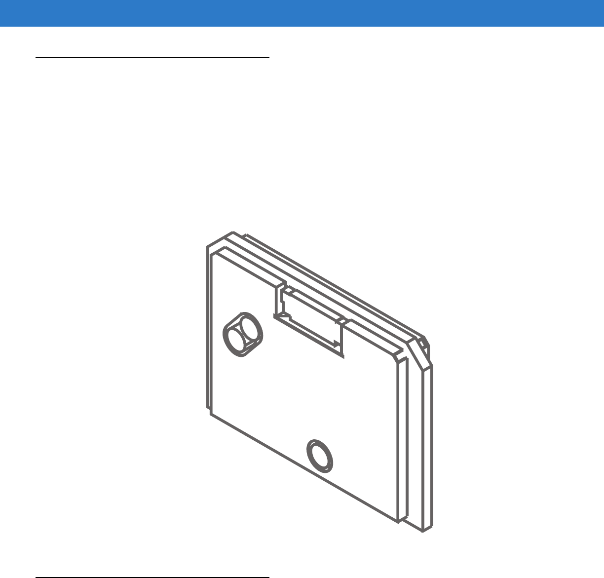
Figure 1-1
RFID Reader Module
Connections and Ports
See Table Table 2-1 on page 2-4 for a detailed list of the RFID Reader Module connections. The RFID Reader
Module has connections for:
•
Host Port Interface
•
External antenna(s)
•
Thermal Contact Points

1 - 4 RFID Reader Module, Integration Guide
Theory of Operation
The RFID Reader Module is a UHF, US (902 – 928MHz) and EU (865.6 – 867.6MHz), RFID reader module. The
RFID Reader Module can read and write UHF passive RFID tags complying to EPCglobal Gen2 standard.
Commands from the reader are broadcast to the tags on the transmit carrier followed by a CW transmission.
Passive tags are powered by reader energy before communication between the reader to the tag starts. After
decoding the command data, the tags respond by back scattering with encoded data, modulated on the CW
transmission.
The RFID Reader Module can be used in mobile devices to provide the capability for reading EPC Gen2 RFID tags
in the UHF band. Once commanded, the RFID Reader Module interrogates the intended field and listen for RFID
tag backscatter. The RFID Reader Module is a mono-static RFID transceiver module using frequency hopping
spread Spectrum (FHSS) in order to interrogate tags. For normal operating modes, there are 50 US channels over
the 902 to 928MHz ISM Band, and four European channels in the
ETSI(EU) 865.6-867.6MHz band that the radio
hops over in order to communicate to the tags. The read range of the radio is highly dependant on both the RFID
antenna performance, and RF output power.
The RFID Reader Module is designed as an embedded module and is intended to be used as an integral part of an
RFID system.
•
Handheld or portable devices
•
Printers
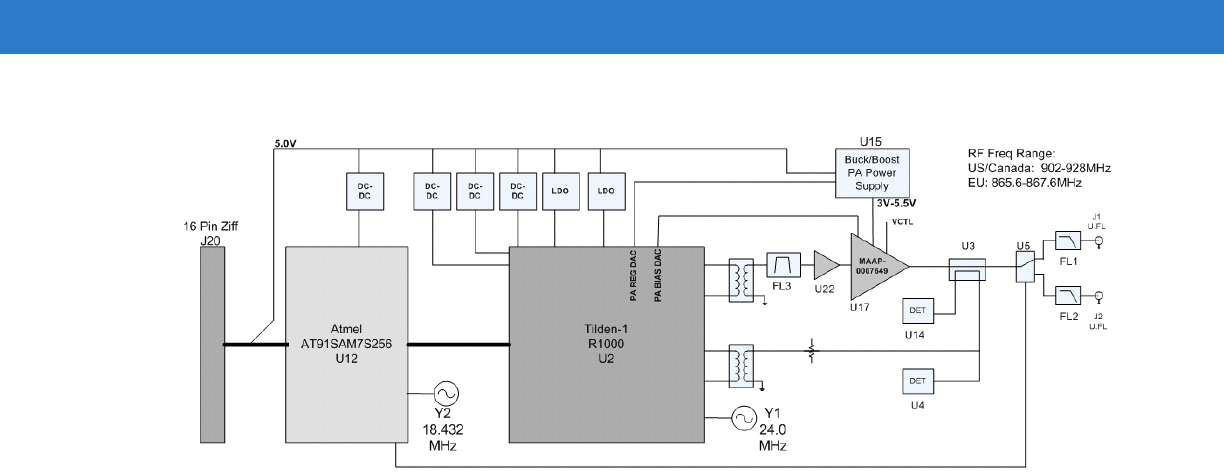
Block Diagram
The RFID Reader Module consists of a UHF transceiver and a processor with interfaces to external antenna(s) and
a host system.
The RFID Reader Module consists of all of the components necessary to make up an RFID Reader Radio for the
915MHz band. The RFID Transceiver IC (R1000) and the Atmel ARM7 Microprocessor (AT91SAM7S256) make up
the major portion of the RFID Reader Radio. In addition, the Power Amplifier (MAAP0007649), RF detectors, and
other RF components complete the EPC Gen2 compliant module.
There are two oscillators on the RFID Reader Module that are used to create the Local Oscillator, and digital timing
clocks for the radio. The 24MHz Oscillator provides a reference clock for both the RF PLL and the RF Transceiver.
The 18.432MHz Oscillator provides the primary clock for the Arm Processor including a reference for the
processors internal PLL.
The Impinj R1000 RFIC (U2) implements a UHF RFID transceiver supporting both 868MHz and 915MHz ISM
bands. The chip set uses a "Zero Intermediate Frequency (ZIF), high intercept point I/Q architecture for the radio.
The architecture contains low-noise, high IP3 amplifiers, quad up/down converters, frequency synthesizers,
low-pass filters, AGC receiver amplifiers, transmit/receive switches, and transmitter power amplifiers.
The Radio control and EPC Gen2 link protocol is implemented in firmware and is in the Atmel
AT91SAM7S256(U12) Arm processor.
Introduction 1 - 5
Figure 1-2
RFID Reader Module Ports/Connectors and Antenna Locations
Receive Path
The received signal from the antenna is fed to directional coupler (U3) and is coupled through the reverse path to
the receive balun, and also to the reverse power detector (U4). The reverse power detector senses RF energy that
is reflected from the antenna and compares it to a threshold each time the transmitter ramps. If the threshold is
exceeded, the transmitter is halted and the RF energy is turned off in order to protect the PA during a fault event.
The receive balun converts the single ended RF signal to a balanced or differential signal before passing it to the
R1000 receive pins for demodulation.
Transmit Path
The transmit path begins with the internal waveform generator in the R1000 (U2) which is up converted and
amplified before leaving the R1000 in a differential/balanced format. The transmit signal is converted to a single
ended format and passed through a Surface Acoustic Wave (SAW) band pass filter (FL3), and then amplified by a
driver amplifier (U22), and finally a Power Amplifier (U17). The output of the power amplifier feeds the input to a
dual directional coupler. The coupler samples the transmitted RF signal using a forward RF power detector (U14).
This detector has a calibrated output that the radio uses to automatically level the transmitter output. Once the
transmit signal leaves the directional coupler, it is fed to a SPDT RF Switch (U5) that is used to feed one of two
identical RF paths. The RF path after the switch passes through a Low Pass Filter (FL1, FL2) and then to the RF
connector (J1, J2).
Microprocessor Control
The RFID Reader Module Atmel processor (AT91SAM7S256, U12) is a memory-integrated microcontroller which
contains the RFID radio system firmware. The primary function of the processor is interfacing with the RF ASIC to
drive the RFID protocol at the MAC level. The Atmel also controls and regulates additional electronics, such as
radio power supplies, final stage signal amplification hardware, and sensors for closed loop functionalities. In
addition, this controller executes host layer communications to receive /interpret/respond to commands,
up-transfer radio link data, as well as store and adjust to radio parameters.
Frequency Generation
The Frequency generation on the RFID Reader Module is derived from a 24MHz crystal oscillator (Y1) reference
that is used to generate the local oscillator (LO) using the internal PLL of the R1000. This LO is used to both up
convert the transmit baseband signal and used to down convert the receive RF signal to baseband for detection.
This LO is in the range of 902MHz to 928MHz for the US module and 865.6-867.6 for the EU module.

1 - 6 RFID Reader Module, Integration Guide

Chapter 2 Installation
Overview
This chapter provides information for configuration, mounting and installing the RFID Reader Module. Physical and
electrical considerations are presented, together with recommended window properties and housing designs.
Mounting Considerations
The RFID reader module housing design must protect the module from impact and adverse environments.
The host housing that integrates the RFID Reader Module must be designed so that it can draw the generated heat
off the radio and out of the host unit. The module has been designed to be efficient in conducting heat from point of
generation to the outside. Thermal slugs are mounted to the board which draw heat from the board to the outside
of the EMI shields. This allows the host device to pull the heat off of the module. Additionally, there are two
thermally conductive channels on the two side edges of the module which are designed to transfer heat from the
module to a thermally conductive bracket. The thermally conductive bracket must be able to dissipate the heat to
the outside of the host device.
Environment
The RFID reader module must be sufficiently enclosed to prevent moisture and/or dust from interfering with the
RFID Reader Module operation.
Grounding
The RFID reader module is grounded through the host interface connector (see Host Interface on page 2-4).
ESD
Always exercise care when handling the module. Use grounding wrist straps and handle in a properly grounded
work area for ESD specifications.
2 - 2 RFID Reader Module, Integration Guide
Location and Positioning
The general location and positioning guidelines provided do not consider unique application characteristics. It is
recommended that an RFID engineer perform an analysis prior to integration.
Using the RFID Reader Module
Identify the capabilities scope and the inputs/commands required to access them.
Some applications require the RFID Reader Module be mounted to read tags that are automatically presented, or
that are presented in a pre-determined location. In these applications RFID reader antenna positioning (with
respect to the tag) is critical. Failure to properly position the RFID reader antenna with respect to the tag may lead
to degraded or unsatisfactory reading performance.
Figure 2-1
Mounting
External Hardware Interfaces
The RFID Reader Module hardware interface include the input voltage, antenna interface and the host interface.
Refer to Appendix A, Technical Specifications for detailed product specifications.
Antenna Interface
Two bi-directional mono-static antenna ports, user selects transceiver port via host command.
U.FL- surface mount
coaxial male c
onnector.
Antenna diversity is supported on RFID Reader Module. Two antenna connectors allow for the use of horizontal
and vertical polarized antennas (optional) in order to achieve optimal read performance for multiple tag
orientations.
The reference antenna specifications are provided in Table C-1 on page C-4.
Installation 2 - 3
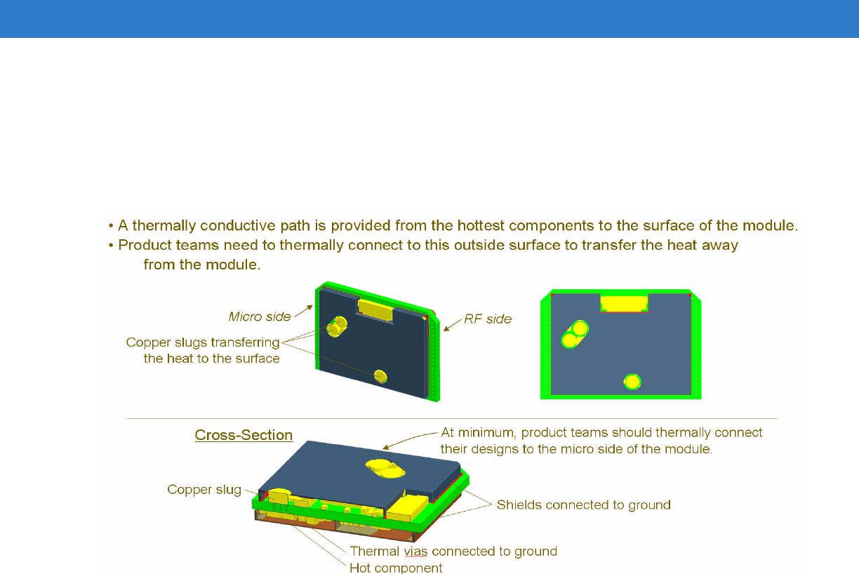
Thermal Interface
Need engineering input for heat dissipation rate.
Figure 2-2
Thermal Management

2 - 4 RFID Reader Module, Integration Guide
Host Interface
The host interface connector consists of a 16 pin ZIF connector:
Table 2-1
RFID Reader Module Host Interface Connector Description
Pin Module
Signal Direction Description
1 GND Input GND
2 TST Input Drive this signal high during reset to copy the ROM boot loader into
Flash. Care MUST be taken to not inadvertently set this signal.
3 UAR-TRXD Input 3.3V, 5V tolerant, RS-232 Serial data to radio module from host.
4 UAR-TTXD Output 3.3V RS-232 Serial data from radio module to host
5 UAR-TRTS Output 3.3V RS-232
6 UAR-TCTS Input 3.3V, 5V tolerant, RS-232
7 VCC Input +5VDC
8 VCC Input +5VDC
9 VCC Input +5VDC
10 WAKE/GPIO1 Input/Output Primary Function: Wake line (edge sensitive). Can be configured as
general purpose output.
11 TX_MUTE_N Input Primary function: logic 0 on this line shuts down the power amplifier
12 RESET_N Input- Reset Line (level sensitive), pull low to reset radio module
13 GPIO2 Input/Output General Purpose I/O
14 GPIO3 Input/Output General Purpose I/O
15 GND Input GND
16 GND Input GND

Installation 2 - 5
Module Control Signals
TST Signal:
The TST signal forces the module microcontroller into a firmware recovery state, which copies a boot loader into
the microcontroller Flash from ROM. Best practices indicate that the correct use of this signal is to follow this
sequence:
Power Off -> Assert TST -> Power On (10 seconds) -> Power Off -> Deassert TST.
Because this state is only recoverable by reprogramming the firmware image, strong caution needs be taken to not
inadvertently assert this signal. Refer to Atmel AT91SAM7S documentation (e.g Atmel 6175H-ATARM-03-Dec-07)
for more in depth documentation on microcontroller function.
UART Signals:
The module communicates in RS-232 timing and protocol, but single ended 3.3V and 0V referenced to ground.
Data rate is 115.2kbaud, 8 data bits, No parity, and one stop bit.
UAR-TRX:
This is the primary signal for serial communications going to the module.
This signal is 3.3V input or 0V input (referenced to ground), and is 5V tolerant.
UAR-TTX:
This is the primary signal for serial communications coming from the module.
This signal is driven actively to 3.3V or 0V referenced level.
UAR-TRTS:
This signal can be optionally enabled or disabled. This signal is flow control output from the module. This
signal is driven actively to 3.3V or 0V referenced to ground.
This signal defaults high for those systems that use flow control as DTEs and wired by null modem type
configuration.
UAR-TCTS:
This signal can be enabled or disabled. This signal is flow control input to the module. This signal is 3.3V input
or 0V input (referenced to ground), and is 5V tolerant.
Note that when the module is actively reading, and CTS is asserted, data will necessarily be buffered. This
buffer is finite, and when it runs out of space, the reader will no longer read more tags into the buffer.
WAKE/GPIO1:
The primary function of this pin is to remove the module from sleep state. Either transition edge (positive or
negative) will effect this change. Typical systems will generate a pulse (two successive transitions), the second
edge will be ignored. There is a slight power advantage to maintain this signal at a high level (avoids fighting
against a pull-up resistor). If a pulse is used to wake the module, its width should be much narrower than the wake
time-out interval.
The WAKE functionality of this signal is in multiplex with the GPIO1 signal. Care should be taken by the module
integrator not to cause contention on this signal (i.e. making GPIO direction output, when WAKE is also actively
driven.
The Wake timing diagram is provided in Appendix B-1, Timing Requirements for RF Activity.

2 - 6 RFID Reader Module, Integration Guide
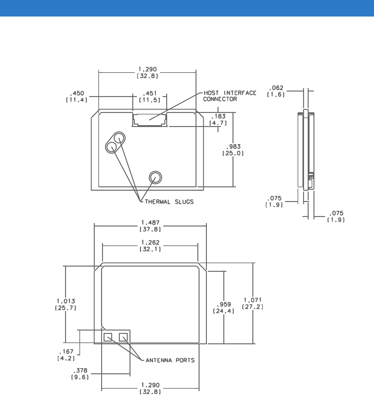
Mechanical Characteristics
The RFID Reader Module mechanical characteristics include the physical dimensions, the weight and the
enclosure, and EMI shielding. Dimensions: 38mm long, by 27mm wide, by 6mm thick.
Enclosure and EMI Shielding
The RFID Reader Module is shielded on both side using two internal removable EMI shields, one on each side of
the board to compartment isolate the RF and digital circuits on the PCB. Each shield consists of a frame soldered
to the PCB and a removable cover.
Thermal Management
A thermally conductive path using copper slugs is provided from the hottest components to the outer surface of the
module. The RFID Reader Module should be thermally integrated to allow heat from the micro side of the module
to be thermally connected to this outside surface to transfer the heat away from the module.
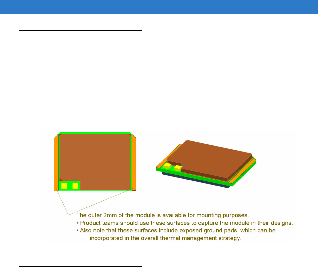
Mounting
The RFID Reader Module is intended to be captured along the side edges. The bracket should be designed of a
thermally conductive material so that it can transfer heat off the board and into the host system which in turn should
be designed to transfer heat out of the host system.
The outer 2mm of the module is available for mounting. These surfaces should be used to capture the module in
the host product.
In addition these surfaces include exposed ground pads, which can be incorporated in the overall thermal
management strategy.
Installation 2 - 7
Note: All dimensions have a 5% tolerthat
Figure 2-3
RFID Reader Module Outline Drawing

2 - 8 RFID Reader Module, Integration Guide
Environmental Characteristics
Thermal Management
The RFID Reader Module shuts down and turns off should the module temperature exceed 80°C. It turns back on
after the module cools off.
As the module starts to get hot, the thermal PID (proportional-integral-derivative) controller kicks in. The objective
of the PID controller is to keep the unit thermal temperature steady at a set point temperature below the 75°C. The
module accomplishes this by over riding the reader duty cycle. When the temperature is below the set point, the
PID increases the reader duty cycle close to 100%. When the temperature is above the set point temperature the
duty cycle is decreased to allow the unit to cool down. If the module is too hot, read rate may decrease.
See Appendix A, Technical Specifications for detailed Temperature, Humidity, ESD, Shock, and Vibration
specifications.
Read/Write Ranges
The reader module has typical read/write range based on a standard configuration. The detailed parameters are
provided in Table A-6 on page A-7. These reference values may change depending on tag type, antenna and
environmental conditions. The actual range values are also effected by the reflective and absorption properties of
the material under the tag.

Appendix A Technical Specifications
Technical Specifications
The following tables summarize the RFID Reader Module intended operating environment and general technical
hardware specifications.
RFID Reader Module
The following table summarizes the technical specifications:
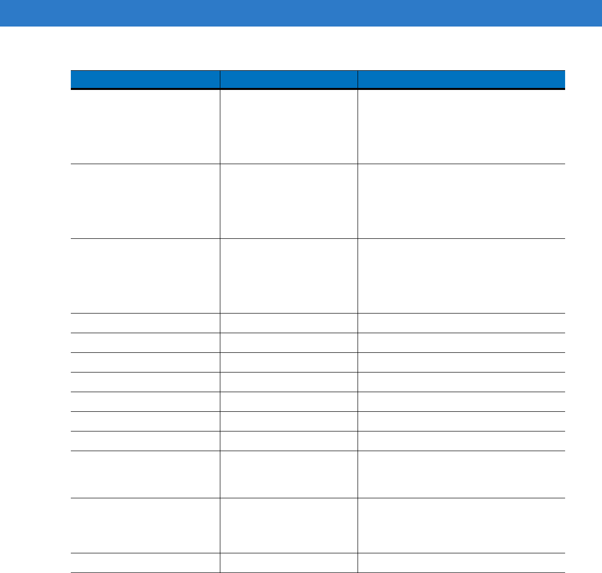
Table A-1
RFID Reader Module Technical Specifications
Item RFID Reader Module
Physical Characteristics
Dimensions ~38mm x 27mm x 6mm
Compliance
Data Capture Options Gen2 tags
ISO 18000-6C
EPC Class1, Gen2
User Environment
Operating Temperature -4°F to 122°F (-20°C to 50°C)*
*This environment is defined as the specific temperature envelope containing the
Sailfish radio product. If embedded within a host product, the envelope is the
internal ambient temperature of the host under the hosts operating conditions.
Storage Temperature -40° to 158° F / -40° to 70° C
Thermal Shock -20° C to +65° C, 30 min dwell, 100 cycles
Humidity 5% to 95% non condensing
Drop Specification 30 in. / 76.2 cm bench handling
Shock
Shock: 100g +/- 5% applied via the mounting surfaces @ -20C, 23C, and 60C
for a period of 0.85 +/- 0.05 ms (3 axes), 6 shocks per axis.
Vibration
Vibration: 20Hz to 2KHz, 15gs Pk Sine.

A - 2 RFID Reader Module, Integration Guide
ESD +/-2kVdc contact to pin
RFID Characteristics
Frequency Range FCC (US) 902-928MHz and Canada
ETSI (EU) 865.6-867.6MHz
RF Output power 10mW to 1000mW
•
1000mW max (MRM, XRM)
•
500mW max (DRM)
Interface
Antenna Connector Hirose U.FL,
in accordance with motorola specifications
2 monostatic antenna connectors, see
Reference Antenna on page C-4
.
UART 115.2kBPS
Host Connector 16 Pin ZIF, in accordance with motorola specifications
Power Requirements
Input Voltage (VCC)
5.0+/- 0.25 VDC
DC Current See Table A-2 on page A-3
Regulatory
Electrical Safety Certified to UL60950-1, CSA C22.2 No. 60950-1, EN60950-1, IEC 60950-1.
RF Exposure USA — FCC Part 2, FCC OET Bulletin 65 Supplement C; Canada — RSS-102.
RFID USA — FCC Part 15.247, 15.205, 15.209: Canada — RSS-210
EU EN 302 208.
EMI/RFI USA — FCC Part 15; Canada — ICES 0003 Class B;
EU: EN 301 489-1; EN 301 489-3.
Table A-1
RFID Reader Module Technical Specifications (Continued)
Item RFID Reader Module

Technical Specifications A - 3
Table A-2
RFID Reader Module RF Specification(U.S. Version
Parameter Specification Limit Conditions
RF Frequency Range 902-928MHz 50 channels IAW Table 1 below.
Output Power Capability +10dBm to +30dBm in 0.1dB
steps
+27dBm max in DRM, +30dBm max in
MRM/XRM
Channel Spacing 500KHz(200KHz)
Frequency Accuracy +/- 10 ppm RF Output Power Accuracy
RF Output Power Accuracy
+30dBm
+29dBm
+28dBm
+27dBm
+24dBm
+20dBm
+17dBm
+10dBm
+29.7 dBm +0.2/-0.75 dB
+29.0dBm +/- 0.75 dB
+28.0 dBm +/- 0.75 dB
+27.0 dBm +/- 0.75 dB
+24.0 dBm +/- 1.0 dB
+20.0 dBm +/- 1.0 dB
+17.0 dBm +/- 1.0 dB
+10.0 dBm +/- 2.0 dB
VCC=5.0V, Z0=50Ω,
CW mode, reference to J1 or J2 of RFID
Reader Module. RF Power used within 400 ms
of RF ramp
Power Supply Voltage 5.0VDC +/- 0.25V Voltage required at J20 pin 7 while transmitting
Power Supply Noise/Ripple 100 mvpk-pk max
DC Current Requirements
(CW Mode, MRM and XRM)
+30.0dBm
+29.0dBm
+28.0dBm
+27.0dBm
+24.0dBm
+20.0dBm
+17.0dBm
+10.0dBm
Typ. Max
1200mA 1400mA
1100mA 1300mA
1050mA 1200mA
950mA 1000mA
750mA 800mA
650mA 700mA
640mA 680mA
600mA 625mA
VCC=5.0V, Z0=50Ω,
CW mode, MRM and XRM Profiles
DC Current Requirements
(CW Mode, DRM)
+27.0dBm
+24.0dBm
Typ. Max
1200mA 1400mA
900mA 1100mA
VCC=5.0V, Z0=50Ω,
CW mode, DRM Profiles
IDLE Current Typical Maximum
36mA 50mA
VCC=5.0V, Tilden in reset
Ready Current Typical Maximum
230mA 260mA
VCC=5.0V
Duty Cycle 1% to >90%
A - 4 RFID Reader Module, Integration Guide
Spurious
30MHz to 88MHz
88MHz to 216MHz
216MHz to 902MHz
928MHz to 960MHz
< -42.7dBm
< -42.2dBm
< -40.2dBm
< -38.2dBm
VCC=5.0V, Z0=50Ω
AT CH0(902.75MHZ), CH24(914.75MHz),
CH49(927.25MHz)
Spectral Mask
(Link Profile 2/DRM)
+/- 100KHz
+/- 200KHz
+/- 300KHz
< 30 dBch
< 60 dBch
< 65 dBch
Measured at specified offset at Ch24, Z0=50Ω,
For +27dBm and +24dBm
Spec Analyzer Settings: Span=1MHz,
RL=30dBm, Res BW=3KHz, Video BW=300Hz
Spectral Mask
(Link Profile 1/MRM)
+/- 500KHz
+/- 1000KHz
+/- 1500KHz
< 20 dBch
< 50 dBch
< 60 dBch
Measured at specified offset at Ch24, Z0=50Ω,
For +30dBm and +24dBm
Spec Analyzer Settings: Span=1MHz,
RL=30dBm, Res BW=3KHz, Video BW=300Hz
Modulation Depth 80% ≤ Depth ≤ 100% Ch 24, Z
0
=50Ω
Modulation Rise time ≤ 8.5μs Ch 24, Z
0
=50Ω
Modulation Fall time ≤8.5μs Ch 24, Z
0
=50Ω
RF Pulse width 6.625μs ≤PW≤13.125μs Ch 24, Z
0
=50Ω
RF Power On Rise Time ≤ 500 μs Ch 24, Z
0
=50Ω
RF Power On Settle Time ≤ 1500μs Ch 24, Z
0
=50Ω
RF Power On Ripple ≤ 5% Ch 24, Z
0
=50Ω
Harmonics, conducted
2
nd
Harmonic
3
rd
Harmonic
-60dBc max Measured at +30dBm, Ch24, Z
0
=50Ω
Read Range 6ft. min while frequency
hopping over all channels
while reading 50% of tags
using 15 Tag board array
RF Power=+24dBm, Ref +2dBi Ref Dipole
Antenna with Return Loss = 10 dB min. across
band, link profile 2, using AD222 15 Tag Array
1
Operating Temperature Range T=-20°C≤Tem p≤+50° C
Table A-2
RFID Reader Module RF Specification(U.S. Version
Parameter Specification Limit Conditions
Technical Specifications A - 5
Table A-3
General Specifications
Parameter Specification Notes
RF Output Power Range
10mW to 1000mW 1000mW max (MRM, XRM)
DRM Host Programmable 250-500mW
MRM
XRM
10mW to 1W
Antenna Interface Hirose U.FL 2 monostatic antenna connectors
Host Interface UART 115.2kBPS
Host Interface Connector 16 Pin ZIF, pitch
Mechanical Dimensions ~38mm x 27mm x 6mm See Mechanical Outline
Power Requirements
Input Voltage (VCC) 5.0+/- 0.25 VDC
DC Current (varies with modulation, see specification)
250mW level 700mA nominal at 5.0V Peak current during read
500mW level 1000mA nominal at 5.0V Peak current during read
1000mW level 1500mA nominal at 5.0V Peak current during read
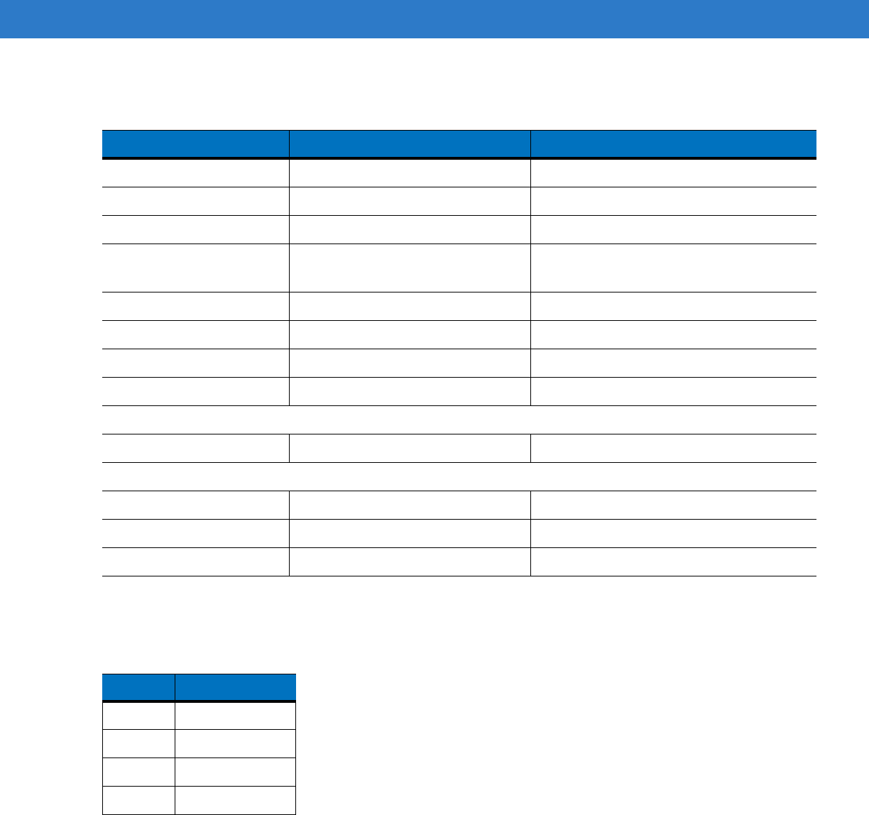
Table A-4
EU Channel Definition
Channel Frequency (MHz)
0 865.70
1 866.30
2 866.90
3 867.50

A - 6 RFID Reader Module, Integration Guide
Table A-5
U.S. Channel Definition
Channel Frequency (MHz) Channel Frequency (MHz)
0 915.75 25 912.25
1 915.25 26 906.25
2 903.25 27 917.25
3 926.75 28 914.25
4 926.25 29 907.25
5 904.25 30 918.25
6 927.25 31 916.25
7 920.25 32 910.25
8 919.25 33 910.75
9 909.25 34 907.75
10 918.75 35 924.75
11 917.75 36 909.75
12 905.25 37 919.75
13 904.75 38 916.75
14 925.25 39 913.25
15 921.75 40 923.75
16 914.75 41 908.25
17 906.75 42 925.75
18 913.75 43 912.75
19 922.25 44 924.25
20 911.25 45 921.25
21 911.75 46 920.75
22 903.75 47 922.75
23 908.75 48 902.75
24 905.75 49 923.25

Technical Specifications A - 7
Reference Performance Characteristics
The expected Reference Performance Characteristics are:
* Add expected read range notes and exceptions here.
Table A-6
RFID Reader Module reference Performance Characteristics
Tag Type Parameters Expected Read Range*
A - 8 RFID Reader Module, Integration Guide
Link Profiles and XRM
The Sailfish module supports all the R1000 Reference Design EPC Gen2 Link Profiles and can be controlled by
the host application to use any of the various profiles listed inTable A-7.
Several link profiles are selectable through a host application. This allows the reader performance to be tailored for
various applications. For example, some link profiles are better suited for close range, high tag populations while
others may be better for long range reading of a few tags. Some link profiles use modulation types that are better
for power efficiency of the reader in that the power amplifier can be biased more efficiently and others are biased
more linear so that the spectrum of the signal is well defined, requiring less bandwidth. In general, the DSB-ASK
modulations used in the MRM (multi-reader mode) link profiles have better power efficiency at the expense of a
broader spectral mask, while the PR-ASK modulation used by the DRM (Dense Reader Mode) link profile 2 use
more power for a given transmit level, but have a tighter spectral mask in order to allow for more readers/less
reader to tag interference in a smaller area.
The Sailfish Module extended the link profiles in order to take advantage of the tighter spectrum of PR-ASK while
allowing for similar power efficiency of the DSB-ASK. This new mode is called XRM and is simply the PR-ASK link
profiles, with the lower biasing of the MRM/DSB-ASK modulations. This is not an EPC certified mode, however it
reads EPC Gen2 tags and passes the MRM spectral mask and is compliant with all the regulatory requirements.
XRM=DRM Modulation at MRM Bias Levels and MRM Spectral Mask
(Benefit of DRM Spectrum with Power Requirements of MRM)
To illustrate the three different modes, some typical peak current requirements are listed in Table A-7. As shown,
DRM requires more current for a given power level. Also, the modulated spectrum of the three most commonly
used link profiles are shown in Figure 1. It is evident, that the MRM spectrum is much broader than DRM or XRM
and this MRM link profile does not offer any significant performance advantage over XRM. The power requirements
for the +27dBm DRM is not significantly less than the current required for the +30dBm MRM and XRM modes,
therefore for the same battery power, the user can achieve more read range and better reader density by selecting
one of the XRM link profiles.
Table A-7
Typical Peak Current for MRM, DRM, XRM for 10dB Return Loss Antenna
RF Power
Level Setting
MRM (LP 1) Peak
Current, mA typ
DRM (LP 2) Peak
Current, mA typ
XRM (LP 18) Peak
Current, mA typ
+30 dBm
1278 N/A 1276
+27dBm
850 1054 852
+24 dBm
784 814 782

Technical Specifications A - 9
Figure A-1
DRM, MRM and XRM Transmit Spectrums
To summarize, there is little spectral advantage of DRM over XRM and the read rate performance are equivalent
since the link parameters are identical. Also, since the XRM power requirements are basically the same as MRM
(better power efficiency), the XRM mode should be the preferred mode for most mobile applications. For this
reason, the default link is link profile 18. See Table A-8 on page A-10 for the link profile details.

A - 10 RFID Reader Module, Integration Guide
:
* Default setting
Table A-8
Motorola Modified Link Profiles With Three Bias Schemes
Selector Mod-type Bias Tari (uS) MLF (KHz) Data Rate
(kbps)
0 DSB-ASK MRM 25.00 FM0 40.00 40
1 DSB-ASK MRM 12.50 M=2 160.00 80
2 PR-ASK DRM 25.00 M=4 250.00 62.5
3 PR-ASK DRM 25.00 M=4 300.00 75
4 DSB-ASK MRM 6.25 FM0 400.00 400
5 PR-ASK DRM 25.00 M=2 250.00 125
6 PR-ASK DRM 25.00 M=4 250.00 62.5
7 PR-ASK DRM 25.00 M=4 300.00 75
8 PR-ASK DRM 25.00 M=4 200.00 50
16 DSB-ASK MRM 25.00 FM0 40.00 40
17 DSB-ASK MRM 12.50 M=2 160.00 80
18* PR-ASK XRM 25.00 M=4 250.00 62.5
19 PR-ASK XRM 25.00 M=4 300.00 75
20 DSB-ASK MRM 6.25 FM0 400.00 400
21 PR-ASK XRM 25.00 M=2 250.00 125
22 PR-ASK XRM 25.00 M=4 250.00 62.5
23 PR-ASK XRM 25.00 M=4 300.00 75
24 PR-ASK XRM 25.00 M=4 200.00 50
Appendix B Timing
Power Up and Reset Timing
Table B-1, shows the required timing requirements for RF activity for various modes.
Table B-1
Timing Requirements for RF Activity
Mode Current (mA)
Typical
Power (mW)
Typical
Time to RF on,
Typical (ms)
Ready 230 1150 2.9
Idle (Tilden in reset) 36 180 25.5
Relax (Lowest Pwr level with active UART) 22 110 28.5
Sleep (requires WAKE) 5 25 26.9
OFF (No 5V to RFID Reader Module) 0 0 ~81
B - 2 RFID Reader Module, Integration Guide
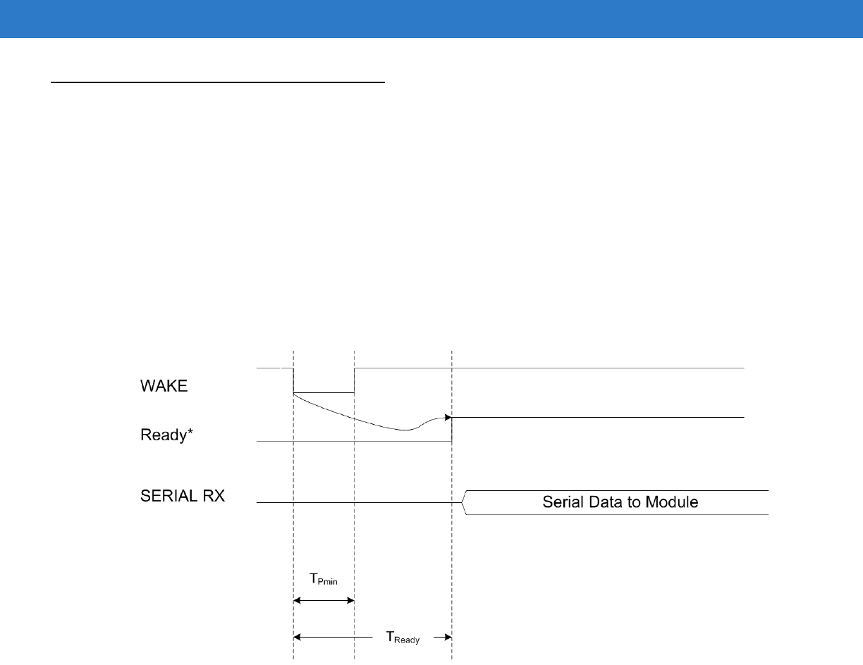
WAKE/GPIO1
The primary function of this pin is to wake the module from the sleep state. Either transition edge (positive or
negative) will effect this transition. The module goes to the Ready State and waits for a command from the host
system over the serial port.
Typical systems generate a pulse (two successive transitions), the second edge is ignored. There is a slight power
advantage to maintain this signal at a high level (avoids fighting against a pull-up resistor). If a pulse is used to
wake the module, the width must be narrower than the wake timeout interval.
The WAKE functionality of this signal is in multiplex with the GPIO1 signal. The integrator must excercise care not
to cause contention on this signal (i.e. making GPIO direction output, when WAKE is also actively driven.
*Ready to receive command (CSM:WAIT state). Not an externally visible signal.
Figure B-1
RFID Reader Module Wake Signals
Timing B - 3
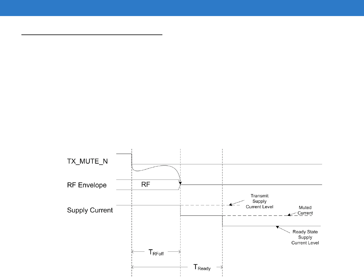
TX_MUTE_N
This signal provides a hard real-time method to mute the RF output of the module and is useful for rapidly
reduceing module current consumption. The PA is shut down directly through hardware. A brief time later, the
microcontroller acts on the TXMUTE event by shutting down other radio hardware and returning the module to
Ready State.
The example (see Figure B-2) shows RF being on prior to assertion of TX_MUTE_N. If Module receives an RF
inducing command (e.g. Inventory, Write, etc...) while TX_MUTE_N is already asserted, RF is not generated.
In both of these instances a TXMUTE error is generated in "Command End "Packet sent out through the UARTTX
signal.
Figure B-2
RFID Reader TX Mute Signals

B - 4 RFID Reader Module, Integration Guide

Appendix C Regulatory Requirements
User Guide Statements
Many of the regulatory statements are dependent on the final product application. Motorola recommends that the
Integrator seeks the advice from an accredited test laboratory. The following statements are provided for guidance
only.
General Statements
Any changes or modifications not expressly approved by Motorola, Inc. could void the user's authority to operate
the equipment.
FCC Statements
Co-located statement
To comply with FCC RF exposure compliance requirement, the antenna used for this transmitter must not be
co-located or operating in conjunction with any other transmitter/antenna except those already approved in this
filling.
Handheld Devices
To comply with FCC RF exposure requirements, this device must be hand operated with a minimum separation
distance of 23 cm or more from a person's body. Other operating configurations should be avoided.
Remote and Standalone Antenna Configurations
To comply with FCC RF exposure requirements, antennas that are mounted externally at remote locations or
operating near users at stand-alone desktop of similar configurations must operate with a minimum separation
distance of 23 cm from all persons.
Radio Frequency Interference Requirements - FCC

C - 2 RFID Reader Module, Integration Guide
Note: This equipment has been tested and found to comply with the limits for a Class B digital device, pursuant to
Part 15 of the FCC rules. These limits are designed to provide reasonable protection against harmful interference
in a residential installation. This equipment generates, uses and can radiate radio frequency energy and, if not
installed and used in accordance with the instructions, may cause harmful interference to radio communications.
However there is no guarantee that interference will not occur in a particular installation. If this equipment does
cause harmful interference to radio or television reception, which can be determined by turning the equipment off
and on, the user is encouraged to try to correct the interference by one or more of the following measures:
•
Reorient or relocate the receiving antenna
•
Increase the separation between the equipment and receiver
•
Connect the equipment into an outlet on a circuit different from that to which the receiver is connected
•
Consult the dealer or an experienced radio/TV technician for help.
Radio Transmitters (Part 15)
This device complies with Part 15 of the FCC Rules. Operation is subject to the following two conditions: (1) this
device may not cause harmful interference, and (2) this device must accept any interference received, including
interference that may cause undesired operation.
Industry Canada Statements
Radio Frequency Interference Requirements
This Class B digital apparatus complies with Canadian ICES-003.
Cet appareil numérique de la classe B est conforme à la norme NMB-003 du Canada.
Radio Transmitters
This device complies with RSS 210 of Industry & Science Canada. Operation is subject to the following two
conditions: (1) this device may not cause harmful interference and (2) this device must accept any interference
received, including interference that may cause undesired operation.
Label Marking: The Term "IC:" before the radio certification only signifies that Industry Canada technical
specifications were met.
IC Radiation Exposure Statement (only applicable of mobile use only)
This equipment complies with IC radiation exposure limits set forth for an uncontrolled environment. This
equipment should be installed and operated with minimum distance 23cm between the radiator & your body.
Antenna (only if the antenna is detachable & selectable by the user)
To reduce potential radio interference to other users, the antenna type and its gain should be so chosen that the
equivalent isotropically radiated power (EIRP) is not more than that permitted for successful communication.
This radio module has been designed to operate with an antenna having a maximum gain of 2dBi, requirements
are detailed in Table C-1 on page C-4.
Antenna having a higher gain is strictly prohibited per regulations of Industry Canada. The required antenna
impedance is 50 ohms.

Regulatory Requirements C - 3
European Statements
Marking and European Economic Area (EEA)
The use of RFID for use through the EEA, have the following restrictions:
•
Maximum radiated transmit power of 2W ERP on 4 channels, frequencies: 865.7MHz, 866.3MHz, 866.9MHz
& 867.5MHz.
Statement of Compliance (embedded radio card, Model: 21-121560)
Motorola, Inc., hereby, declares that this device is in compliance with the essential requirements and other relevant
provisions of Directive 1999/5/EC. A Declaration of Conformity may be obtained from
http://www2.symbol.com/doc/
Regulatory Requirements
The following information summarize the RFID Reader Module regulatory requirements.
Legal Disclaimer
This appendix contains the regulatory requirements information. The information should be used with the
understanding that Motorola is not engaged in rendering any legal, regulatory or other professional opinion. Each
country has specific laws and regulations governing the use of radio communications. Consult the official code for
each country of interest. Motorola does not warrant the accuracy of the information contained herein and accepts
no liability or responsibility for any use or misuse of the information.
Motorola's wireless devices are designed to be compliant with rules and regulations in locations they are sold.
Any changes or modifications to Motorola equipment, not expressly approved by Motorola, could void the user's
authority to operate the equipment.
Final Product Compliance
This module has been regulatory approved for integrations which meet the following conditions:
1. The radio integration is embedded.
2. The antenna must be installed such that 23 cm is maintained between the antenna and users.
3. The 'Type' and 'Gain' of the antenna selected for the integration of the external antenna must meet the
requirements, detailed in Table C-1 on page C-4.
Any use outside of these conditions will require a re-approval. Motorola can advise on the use of an accredited test
laboratory for advice. The product certification process may take from a few weeks to several months.
The integrator is responsible to determine what additional specific regulatory requirements are required of the
country in which the product will be marketed. Final product may require non-radio frequency approvals such as
Product Safety, EMC, and SAR.

C - 4 RFID Reader Module, Integration Guide
Reference Antenna
A reference antenna has been used during the approval process.
Specific details of the reference antenna used for testing is detailed in the table below.
Important Note:
Use of an antenna which is the same 'type' (e.g. Dipole) and has a gain equal to or less that the reference antenna
can be used without recertification.
Use of an alternative antenna, different 'type' or same 'type' but higher gain will invalidate the country approvals.
Under this instant the OEM integrator is responsible for re-evaluating the end product and obtaining separate
approvals.
Antenna Type: Dipole
Antenna Characteristics:
Table C-1
Motorola Dipole Reference Antenna, Performance Characteristics
Parameters Specification
Operational Frequency FCC(US) 902-928MHz
ETSI(EU) 865.6-867.6MHz
Gain (Peak) +2 dBi Max (includes coax cable/connector RF losses, vertical component or horizontal)
Note:
This device was approved with a 2 dBi gain dipole antenna; if a higher gain or
another type of antenna is used (i.e. other than a dipole) then re-testing and a FCC Type II
Permissive Change submission is required.
VSWR 1.4.1 (Typ)
Polarization Linear
Impedance 50 ohms
Dimensions 4.7 x 2.3 inches
Connector SMA-Female
RF Power - max 1000mW

Regulatory Requirements C - 5
Regulatory Standards
This module has been approved to comply with the standards listed below
Regulatory Approvals
This card is approved in the following countries US, Canada and the following EU countries:
Austria, Belgium, Bulgaria, Czech Republic, Cyprus, Denmark, Estonia, Finland, France, Germany, Greece,
Hungary, Iceland, Ireland, Italy, Latvia, Liechtenstein, Lithuania, Luxembourg, Malta, Netherlands, Norway, Poland,
Portugal, Romania, Slovak Republic, Slovenia, Spain, Sweden, Switzerland and the United Kingdom
Radio Card Regulatory Markings
Regulatory markings are applied to the device signifying the radio (s) are approved for use in the following
countries: United States, Canada, and Europe*.
Please refer to the Motorola Declaration of Conformity (DoC) for details of other country markings. This is available
at http://www2.symbol.com/doc/.
*Note: Europe includes, Austria, Belgium, Bulgaria, Czech Republic, Cyprus, Denmark, Estonia, Finland, France,
Germany, Greece, Hungary, Iceland, Ireland, Italy, Latvia, Liechtenstein, Lithuania, Luxembourg, Malta,
Netherlands, Norway, Poland, Portugal, Romania, Slovak Republic, Slovenia, Spain, Sweden, Switzerland and the
United Kingdom.
National Country Requirements
United States of America
The radio card is approved under the requirements of the FCC.
End-product requirements with this module installed should include:
•
FCC Part 15 (emissions class B)
Table C-2
Approved Compliance Standards
Requirement Compliance Standard
Electrical Safety: Certified to UL / cUL 60950-1, IEC / EN60950-1
RF USA: FCC 47CFR Part 15.247, 15.215,
15.205,15.203, 15.209, 15.247
Canada: RSS-210
EU: EN 302 208
EMI/EMS/EMC: North America: FCC Part 15
Canada: ICES 003 Class B
EU: EN 301 489-1, EN 310 489-3

C - 6 RFID Reader Module, Integration Guide
Final product markings must include:
IMPORTANT NOTES
1. Co-location
The FCC approval EXCLUDES co-location with any other transmitter.
If this Module is co-located with another transmitter (e.g., Bluetooth module), the OEM is integrator is
responsible for re-evaluating the end product and obtaining a separate FCC authorization.
Motorola recommends the use of an accredited Laboratory to carry out the necessary tasks.
2. Portable Use
The FCC approval of the module covers 'mobile' applications.
If the final product used in a manner where the antenna is closer than 23cm from the user (portable use), the
OEM is integrator is responsible for re-evaluating the end product and obtaining a separate FCC authorization.
Motorola recommends the use of an accredited Laboratory to carry out the necessary tasks.
Canada
The radio part is already approved under the requirements of Industry Canada.
End-product requirements with this module installed should include:
•
Canadian Interference-Causing Equipment Regulations (ICES-003).
If the final product used in a manner where the antenna is closer than 23cm from the user (portable use), the OEM
is integrator is responsible for re-evaluating the end product and obtaining a separate IC approval.
Motorola recommends the use of an accredited Laboratory to carry out the necessary tasks.
Final product markings must include:
Contains an approved Radio Module
Model: 21-121559
FCC ID: UZ721121559
Contains an approved Radio Module
Model: 21-121559
IC ID: 109AN-21121559

Regulatory Requirements C - 7
European Union
The radio part is already approved under the R&TTE Directive 99/5/EC.
The final product must comply with all applicable European Directives such as EMC and Product Safety.
Care should be taken as a product might fall under the scope of other directives or standards depending on the
type of product e.g. Medical Directive, Potentially Explosive Atmospheres etc.
End-product requirements with this module installed should include:
•
EMC Tests (the applicable standard depends upon the intended operational environment)
•
Electrical Safety Tests
EC Directives require integrators document their compliance activities in a Technical Construction File (TCF).
The following items should be included in the final product TCF:
•
Notified Body Opinion (used to demonstrate compliance under the R&TTE Directive for Radio, EMC and
Product Health and Safety)
•
EU Declaration of Conformity
Important Note:
A 'Declaration of Conformity' must be issued to cover the final product.
Final product markings must include:
Final product markings must include:
Note: The Notified Body Number that will replace XXXX.
Contains an approved Radio Module
Model: 21-121560

C - 8 RFID Reader Module, Integration Guide

Index
B
block diagram . . . . . . . . . . . . . . . . . . . . . . . . . . . . . . 1-4
bullets . . . . . . . . . . . . . . . . . . . . . . . . . . . . . . . . . . . . . viii
C
configuration . . . . . . . . . . . . . . . . . . . . . . . . . . . . . . . . vii
conventions
notational . . . . . . . . . . . . . . . . . . . . . . . . . . . . . . . viii
D
drop specification . . . . . . . . . . . . . . . . . . . . . . . . . . . . A-1
E
electrical safety . . . . . . . . . . . . . . . . . . . . . . . . . . . . . A-2
H
humidity . . . . . . . . . . . . . . . . . . . . . . . . . . . . . . . . . . . A-1
I
information, service . . . . . . . . . . . . . . . . . . . . . . . . . . . viii
O
operating temperature . . . . . . . . . . . . . . . . . . . . . . . . A-1
operation . . . . . . . . . . . . . . . . . . . . . . . . . . . . . . . . . . 1-4
S
storage temperature . . . . . . . . . . . . . . . . . . . . . . . . . A-1
T
theory of operation . . . . . . . . . . . . . . . . . . . . . . . . . . 1-4
U
unpacking . . . . . . . . . . . . . . . . . . . . . . . . . . . . . . . . . 1-3
W
weight . . . . . . . . . . . . . . . . . . . . . . . . . . . . . . . . . . . . A-1

Index - 2 RFID Reader Module, Integration Guide

72E-121701-01 Revision A - April 2009
Motorola, Inc.
One Motorola Plaza
Holtsville, New York 11742, USA
1-800-927-9626
http://www.symbol.com
MOTOROLA and the Stylized M Logo and Symbol and the Symbol logo are registered in the U.S. Patent and Trademark Office.
All other product or service names are the property of their registered owners.
© Motorola, Inc. 2009