Zebra Technologies AP30240705 Wireless Modem User Manual
Zebra Technologies Corporation Wireless Modem Users Manual
Users Manual

MOTOMESH 1.0
Mesh Wireless Router
Users Guide
September 2005
6881011Y53-O
MOTOMESH 1.0 Mesh Wireless Router Users Guide
6881011Y53-O September 2005
ii
This page intentionally left blank.
MOTOMESH 1.0 Mesh Wireless Router Users Guide
6881011Y53-O September 2005
iii
Copyrights
The Motorola products described in this document may include copyrighted Motorola computer programs. Laws in the United
States and other countries reserve for Motorola certain exclusive rights for copyrighted computer programs. Accordingly, any
copyrighted Motorola computer programs contained in the Motorola products described in this document may not be copied or
reproduced in any manner without the express written permission of Motorola. Furthermore, the purchase of Motorola products
shall not be deemed to grant either directly or by implication, estoppels or otherwise, any license under the copyrights, patents or
patent applications of Motorola, except for the normal nonexclusive, royalty-free license to use that arises by operation of law in
the sale of a product.
Disclaimer
Please note that certain features, facilities and capabilities described in this document may not be applicable to or licensed for use
on a particular system, or may be dependent upon the characteristics of a particular mobile subscriber unit or configuration of
certain parameters. Please refer to your Motorola contact for further information.
Trademarks
Motorola, the Motorola logo, and all other trademarks identified as such herein are trademarks of Motorola, Inc. All other
product or service names are the property of their respective owners.
Copyrights
© 2005 Motorola, Inc. All rights reserved. No part of this document may be reproduced, transmitted, stored in a retrieval system,
or translated into any language or computer language, in any form or by any means, without the prior written permission of
Motorola, Inc.
MOTOMESH 1.0 Mesh Wireless Router Users Guide
6881011Y53-O September 2005
iv
This page intentionally left blank.

6881011Y53-O September 2005
v
Table
of
Contents
Contents
.............................................
.
.
.
.
Chapter 1: Product Introduction ............................................................................1-1
Mesh Wireless Router Defined ........................................................................................................................ 1-1
Additional MWR Features.............................................................................................................................................1-1
MWRs Role within a MOTOMESH Wireless Network....................................................................................... 1-2
Product Specifications...................................................................................................................................... 1-3
Chapter 2: MWR Device Installation ......................................................................2-1
Software Requirements......................................................................................................................................... 2-1
MWR Hardware Installation Notes ...................................................................................................................... 2-1
Equipment Specification .................................................................................................................................. 2-2
Optional Antennas .........................................................................................................................................................2-3
MWR Device Label .......................................................................................................................................................2-3
MWR MAC Address Table ...........................................................................................................................................2-4
MWR Device Assembly .................................................................................................................................. 2-5
MWR Device Deployment and Installation..................................................................................................... 2-6
Assembling the MWR Device .......................................................................................................................................2-6
Initial MWR Device Configuration Information............................................................................................................2-6
Device Connectivity Testing..........................................................................................................................................2-7
Chapter 3: Device Configuration............................................................................3-8
Accessing the Device Administration Web Pages................................................................................................ 3-8
Administrator and User Account Information.................................................................................................. 3-9
Viewing the Device Administration Home Page as an Administrator................................................................ 3-10
Viewing the Device Administration Home Page as a Normal User............................................................... 3-11
Viewing the MWR Device Administration Configuration Page ........................................................................3-11
Device Settings Section.................................................................................................................................. 3-12
Bridge Addressing Section............................................................................................................................. 3-12
Additional Information about the Network DHCP Setting ..........................................................................................3-13
Additional Information about the Statically Provisioned Setting.................................................................................3-13
Security Settings Section (Authentication) .................................................................................................... 3-14
Viewing the MWR Configuration Page as a Normal User ............................................................................ 3-15
Chapter 4: Device Maintenance..............................................................................4-1
Changing the Web Interface Password................................................................................................................. 4-1
Updating the Device Firmware............................................................................................................................. 4-3
MOTOMESH 1.0 Mesh Wireless Router Users Guide
6881011Y53-O September 2005
vi
Resetting the MWR via the Device Web Page ..................................................................................................... 4-4
Restoring Factory Settings.................................................................................................................................... 4-6
Chapter 5: Customer Information ..........................................................................5-1
Customer Service Information.............................................................................................................................. 5-1
Obtaining Support............................................................................................................................................ 5-1
System Information........................................................................................................................................................5-1
Return Material Request ................................................................................................................................................5-2
Radio Products and Services Division ...........................................................................................................................5-2
Radio Products and Services Division Telephone Numbers.....................................................................................5-2
Returning System Components to Motorola..................................................................................................................5-2
Returning FREs..............................................................................................................................................................5-2
Chapter 6: Certification and Safety Information...................................................6-1
FCC Regulatory Information................................................................................................................................ 6-1
FCC RF Radiation Exposure Statement........................................................................................................... 6-1
Safety Information for the MOTOMESH Products.............................................................................................. 6-2
Safety Certification............................................................................................................................................... 6-2

6881011Y53-O September 2005
vii
List
of
Figures
List of Figures
.............................................
.
.
.
.
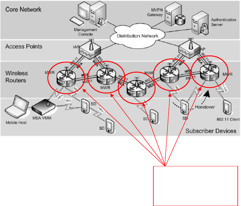
Figure 1-1 The MWR Device in Context of the Wireless MOTOMESH Network...............................1-2
Figure 2-1 Infrastructure Device Product Label (sample) .....................................................................2-3
Figure 2-2 Infrastructure Device External Connection Points...............................................................2-5
Figure 2-3 Infrastructure Device Mounting Brackets ............................................................................2-5
Figure 3-1 MOTOMESH Sample Web Interface Login Screen............................................................3-9
Figure 3-2 MOTOMESH Device Administration Home Page (Super User Login)............................3-10
Figure 3-3 MOTOMESH Device Administration Configuration Page ...............................................3-12
Figure 3-4 MWR Configuration Page (Normal User Account)...........................................................3-15
Figure 4-1 Select Change Admin Password...........................................................................................4-1
Figure 4-2 Enter New Password Screen.................................................................................................4-2
Figure 4-3 Password Changed Confirmation.........................................................................................4-2
Figure 4-4 Password Change Completed...............................................................................................4-3
Figure 4-5 Update Device Firmware Web Page ....................................................................................4-3
Figure 4-6 Confirm Upload Window for Firmware Update ..................................................................4-4
Figure 4-7 Firmware Upload Progress Web Page..................................................................................4-4
Figure 4-8 Device Reset Prompt Web Page...........................................................................................4-5
Figure 4-9 Device Reset in Progress Page.............................................................................................4-6
Figure 4-10 Restore Factory Settings Web Page.................................................................................4-7
Figure 4-11 Confirm Changes Window for Restore Factory Settings.................................................4-7
Figure 4-12 Factory Settings Restored Web Page...............................................................................4-8
Figure 4-13 Ready to Reset Device Web Page....................................................................................4-8
Figure 4-14 Resetting Device Web Page.............................................................................................4-9
List of Figures
6881011Y53-O September 2005
viii
This page intentionally left blank.

6881011Y53-O September 2005
ix
List
of
Tables
List of Tables
.............................................
.
.
.
.
Table 1-1 MOTOMESH MWR7300 Specifications ............................................................................1-3
Table 2-2 MOTOMESH Infrastructure Device Radio Characteristics.................................................2-2
Table 2-3 Recommended Antennas for Infrastructure Devices............................................................2-3
Table 2-4 MWR MAC Address Table..................................................................................................2-4
Table 3-1 Login Screen Default User Names and Passwords ..............................................................3-9
Table 3-2 Device Settings Section (Configuration Tab) ....................................................................3-12
Table 3-3 Bridge Addressing Section (Configuration Tab)................................................................3-12
Table 3-4 Device Web Interface - Security Settings Section (Configuration Tab) ............................3-14
List of Procedures
6881011Y53-O September 2005
x
This page intentionally left blank.

6881011Y53-O September 2005
xi
List
of
Procedures
List of Procedures
.............................................
.
.
.
.
Procedure 2-1 Assembling the MWR Device.....................................................................................2-6
Procedure 2-2 Testing MWR Device Connectivity ............................................................................2-7
Procedure 3-1 Accessing the MWR Device Administration Web Interface.......................................3-8
List of Procedures
6881011Y53-O September 2005
xii
This page intentionally left blank.

6881011Y53-O September 2005
1-1
Chapter
1
Chapter 1: Product Introduction
.............................................
.
.
.
.
This guide will assist you with the use, installation, and configuration of the MWR7300.
Mesh Wireless Router Defined
The Mesh Wireless Router (MWR) is a wireless device that is primarily
deployed to seed and extend the range between IAPs and Subscriber
Devices while simultaneously increasing the spectral efficiency of the
network. MWR functionality includes:
• Maximum continuous data rate support ranging from
approximately 900 Kbps for 4.9 GHz MEA components
• Maximum continuous data rate support of up to 20 Mbps
for stationary 2.4 GHz 802.11 devices.
• Fixed reference for Geo-Location services
• Dynamic Route Selection
• Range Extension for all other network devices
• Automatic Load Balancing
• Network capacity optimization through small packet consolidation
Additional MWR Features
The Mesh Wireless Router (MWR) efficiently combines the functionality of a Wireless Router with
two internal high-speed Ethernet ports to support a total of six IP addresses. This allows a network of
IP-enabled devices to be directly addressed, accessed and managed over the MOTOMESH network.
Additional IP devices/addresses can be supported by simply linking the connected devices through a
NAT capable router.
Chapter 1: Product Introduction
6881011Y53-O September 2005
1-2
MWRs Role within a MOTOMESH Wireless Network
.............................................
.
.
The MWR and the IAP are considered as fixed Infrastructure devices. Infrastructure devices provide
area coverage access for Subscriber Devices (SDs) to the wired network. IAPs act as the principal
network management interface for associated MWRs and SDs. MWRs provide standard 802.11
authentications and access to the Radius server.
Both device types provide a fixed location reference for Geo-Location and wireless routing for
subscriber devices in the area of coverage.
Figure 1-1 The MWR Device in Context of the Wireless MOTOMESH Network
The MWR device in
context of the
MOTOMESH wireless
network.

MOTOMESH 1.0 Mesh Wireless Router Users Guide
6881011Y53-O September 2005
1-3
Product Specifications
The following specifications apply to the MWR7300 as described in the table below:
Table 1-1 MOTOMESH MWR7300 Specifications
MOTOMESH MWR7300 Specifications
2.4GHz Portion 4.9GHz Portion
Spectrum 2.4G – use all 80MHz 4.9G – use 30MHz
Security FIPS 140-2 with a VPN FIPS 140-2 with a VPN
Data Rates (Channel size) motion (20MHz) 802.11b/g
(22MHz) motion (20MHz) 802.11b/g (10MHz)
1 hop 1MB 8.2Mbps 1MB 4.2Mbps
2 hop 1MB 4.1Mbps 1MB 2.1Mbps
3 hop 1MB 2.7Mbps 1MB 1.4Mbps
4 hop 1MB 2.0Mbps 1MB 1.0Mbps
Feature & Functions
• 2.4G unlicensed
• vehicular motion
• fast hand off
• Geo Location (10m accuracy)
• Client & Infra. Meshing
• self-forming/healing/balancing
• synchronous broadband data
• wide area
• low Latency
• 802.11b/g
• QDMA
• 4.9G licensed spectrum
• vehicular motion
• fast hand off
• Geo Location (10m accuracy)
• Client & Infra. Meshing
• self-forming/healing/balancing
• synchronous broadband data
• wide area
• low Latency
• “802.11a-ish” (No standard available)
• QDMA
Backhaul; Requirements
T1 to T3 data rates required at
IAPs
Fixed wired, Canopy, Fiber, or
Microwave
T1 to T3 data rates required at IAPs
Fixed wired, Canopy, Fiber or
Microwave
Appropriate Tier of
Applications Supported Tier 1 – Tier 4 Tier 1 – Tier 4
Equipment for 1 sq. mi CONSULT THE CONFIGURATOR TOOL

Chapter 1: Product Introduction
6881011Y53-O September 2005
1-4
Enterprise Features
• Wireless bridge support
• Wireless client support
• Wireless distribution system
• Layer 2 multicast support (pass-through)
• DHCP Client
• Gateway IP address configurability
• Network Time Protocol (NTP) support
• AES encryption support (client)
• MAC access control lists
• VPN pass-through
• Domain name server configuration
• Web (HTTP) based management interface
• SNMP agent for SNMP-based remote management
• Telnet interface with command-line management
• Configuration of wireless parameters
• Firmware update via TFTP
• BSS Statistics
• Per Station Statistics
Security
VPN FIPS-140-2: Padcom, RadioIP, NetMotion
Encryption 802.11 b/g only – 3 levels
Authentication MEA – EAP via HAS Server, 802.11- Radius EAP, Infrastructure and Client,
Client to Client

6881011Y53-O September 2005
2-1
Chapter
2
Chapter 2: MWR Device Installation
.............................................
.
.
This chapter will provide hardware and software installation information for the MOTOMESH
MWR7300 device.
Software Requirements
.............................................
.
.
There are two ways to install and setup the MWR7300 device: MeshManager or the MOTOMESH
Device Administration web interface.
Between the two available setup methods, MeshManager is the preferred and comprehensive device
setup, configuration, and management method. Prior to using the MeshManager software for device
installation and configuration, ensure that it is installed and running on a network computer.
MeshManager will be used during the device setup process to validate the installation of the device and
to manage it, (as well as other devices) within the wireless network.
The MOTOMESH Device Administration web interface can be used to setup and configure the device
by connecting a PC to the wired interface. Please note that the web interface does not offer all the
features that are provided within the MeshManager application. Additional web interface information
is provided later in the manual.
Detailed information about the MeshManager application is found in the MOTOMESH MeshManager
Users Guide.
MWR Hardware Installation Notes
.............................................
.
.
The MWR (and the IAP) provides a fixed location reference for Geo-Location and wireless routing for
units in the area of coverage.

Chapter 2: MWR Device Installation
6881011Y53-O September 2005
2-2
For a MOTOMESH deployment, a permanent power source for each MWR must be provided. All
infrastructure devices require professional installation to ensure that the installation is performed in
accordance with FCC licensing regulations
Infrastructure devices are fitted with two mounting brackets designed to be attached to light poles and
other probable installation sites. Alternate mounting hardware is available for mounting directly to
posts or structures that are too large for the standard brackets. Optional remote antenna mount
hardware is also available for use with the alternate mounting hardware.
Equipment Specification
The specifications listed in the following table apply for all Infrastructure devices.
Table 2-2 MOTOMESH Infrastructure Device Radio Characteristics
Characteristic 2.4GHz
802.11 b/g
2.4GHz
MEA
4.9GHz
802.11
4.9GHz
MEA
Output Power 23 dBm 24 dBm 23 dBm 24 dBm
RF Modulation CCK/OFDM QDMA OFDM QDMA
Operating Frequency (GHz) 2.412-2.462 2.40-2.48 4.945-4.985 4.950-4.965
Maximum Burst Data Rate 54 Mbps 6 Mbps 18 Mbps 6 Mbps
Spectrum Used 20 MHz 60 MHz 10 MHz 20 MHz
The following list defines the standard hardware components for IAPs and MWRs.
• Device Enclosure with 4 N-type Female Antenna Connector
• 120V A/C Power Cable with a NEMA 5-15 plug
• 4 Antennas with N-type Male Antenna Connector
• Weatherproof RJ-45 Connectors
• Mounting Bracket (Standard and Optional)
The Network Operator must supply the following equipment.
• Mounting Location
• Power Source (120V/240V A/C 50/60 Hz)
• Ethernet connection between the IAP and the MiSC
• (2) 7/16 inch wrenches
MOTOMESH 1.0 Mesh Wireless Router Users Guide
6881011Y53-O September 2005
2-3
Optional Antennas
The following antennas are recommended for use with Infrastructure devices.
Table 2-3 Recommended Antennas for Infrastructure Devices
Manufacturer Part Number Gain Usage
Hyperlink HG2409U 8.5 dBi 2.4 GHz Infrastructure
Maxrad MFB49009NMDC 9dBi 4.9 GHz Infrastructure
Radiall-Larsen R380.500.223 11dBi 4.9 GHz Infrastructure
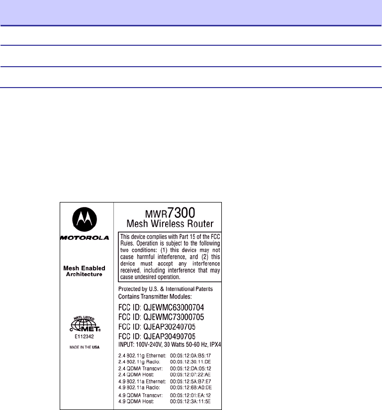
MWR Device Label
The MAC address for each device subcomponent is recorded on a label located on the device
enclosure. Record this number in the provided MWR MAC Address Table section. The MAC
Addresses will be required later to configure and test the device.
Figure 2-1 Infrastructure Device Product Label (sample)

Chapter 2: MWR Device Installation
6881011Y53-O September 2005
2-4
MWR MAC Address Table
Table 2-4 MWR MAC Address Table
MWR Name 2.4 GHz MEA
(MAC/ETH)
2.4 GHz 802.11g
(MAC/ETH)
4.9 GHz MEA
(MAC/ETH)
4.9 GHz 802.11a
(MAC/ETH)
MOTOMESH 1.0 Mesh Wireless Router Users Guide
6881011Y53-O September 2005
2-5
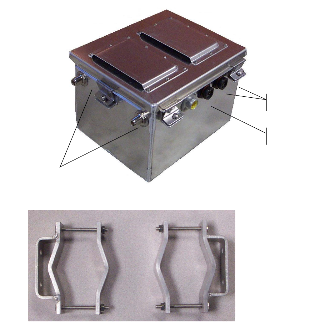
MWR Device Assembly
Figure 2-2 shows the external connection points for the MWR device. Figure 2-3 show the mounting
bracket.
Figure 2-2 Infrastructure Device External Connection Points
Figure 2-3 Infrastructure Device Mounting Brackets
Power Input
Ethernet Port
Antenna Connectors

Chapter 2: MWR Device Installation
6881011Y53-O September 2005
2-6
MWR Device Deployment and Installation
The MWR device requires professional installation to ensure that the installation is performed in
accordance with FCC licensing regulations. All common precautions for grounding and electrostatic
discharge protection should be observed during deployment and installation.
Observe the following additional guidelines when deploying fixed Infrastructure devices (MWR and
IAP):
• The MWR may be mounted on a pole having a diameter of 1-3.5 inches, utilizing the
provided bracket.
• The antenna must have a separation distance of at least 2 meters from the body of all
persons and must not be co-located or operating in conjunction with any other antenna
or transmitter.
• Users and installers must be provided with antenna installation and transmitter operating
conditions to satisfy RF exposure compliance.
• When deploying the MWR, the antenna should be a minimum of 30 inches from any
nearby metal poles to avoid distortion of the RF pattern.
• The installation location must provide power to the MWR.
• It is the responsibility of the Network Operator to ensure that the installation complies
with any local building codes and permits.
Assembling the MWR Device
Use the following procedure to assemble a MWR Device.
Procedure 2-1 Assembling the MWR Device
Initial MWR Device Configuration Information
Prior to attempting configuration of a MWR device, the device must be powered up and have
connectivity to the MiSC.
The Geo-location coordinates are entered into an infrastructure device via the Device Manager
Network management tool installed on the MeshManager server (refer to the MeshManager Users
Guide). Motorola recommends that a DGPS receiver be used to obtain accurate GPS coordinates.
1 Place the brackets at the desired position on the pole.
2 Adjust the position of the box so that the antenna connecters are positioned vertically. Align the antennas
with the N-type connectors on the box and rotate to close.
3 Insert the cable into the external Ethernet port and tighten the connector to ensure a weatherproof seal.
4 Insert the Power Plug into the 4-pin connector.

MOTOMESH 1.0 Mesh Wireless Router Users Guide
6881011Y53-O September 2005
2-7
The longitude, latitude, and altitude values should be entered to a precision of 5
digits following the decimal point.
Device Connectivity Testing
When a MiSC has been setup on the network, verify connectivity to the device using the following
procedure:
Procedure 2-2 Testing MWR Device Connectivity
1 Apply power to the device, the device should be operation in 60 to 120 seconds
2 Obtain the MEA and 802.11 MAC addresses for the device subcomponents that were recorded in the
MAC Address Table earlier in this manual. The address will be in the format 02-05-12-30-xx-yy.
3 Within MeshManager’s Device Manager screen, right-click on the appropriate MWR device in the
Device Tree and select the Ping Device option.
4 Check for a successful response to the Ping command in the Named Device results dialog box. A
successful response to the ping commands verifies connectivity to the device (MWR).
5 Repeat steps 1-4 for additional MWR devices.

Chapter 3: Device Configuration
6881011Y53-O September 2005
3-8
Chapter
3
Chapter 3: Device Configuration
.............................................
.
.
.
.
This chapter contains information which will assist you with accessing the MWR via local web
interface and using the available configuration options.
The web interface offers an incomplete alternative to configuring a MWR device when the network
lacks a Network DHCP server. The recommended device configuration method is to use the
MOTOMESH MeshManager Device Manager application, see the MOTOMESH MeshManager Users
Guide for additional details.
Accessing the Device Administration Web Pages
.............................................
.
.
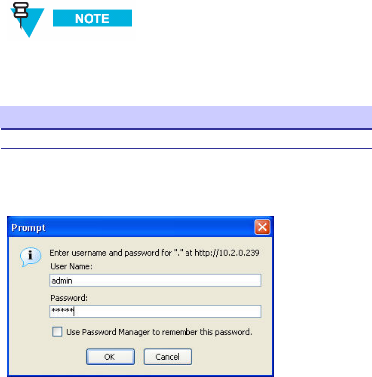
The procedure below describes how to access the MWR device web page.
Procedure 3-1 Accessing the MWR Device Administration Web Interface
6 Find the IP address assigned to the MWR SBC prior to accessing the device administration web interface.
You can use MeshManager’s Device Manager to access the MWRs SBC IP address. To do this, double-
click on the MWR in MeshManager’s Device Tree, and then view the resulting SBC IP address
information shown in the top right pane.
Note that by default, the device’s addressing mode will be set to Network DHCP
which means that the device will use the address assigned to it by the Network
DHCP Server.
If a fixed address was provided by the Network Operator in MeshManager, then that
IP address will be used by the MWR instead of the derived address when the
Statically Provisioned option is in effect.
7 When the IP address is known, open your web browser and enter the IP address of the MWR SBC.
For example, if the MWR SBC address is 10.128.32.1, then the web page would be found at
http://10.128.32.1/.
MOTOMESH 1.0 Mesh Wireless Router Users Guide
6881011Y53-O September 2005
3-9
Administrator and User Account Information
The device has two accounts for the web interface - an Administrative account (Super User), and a
User account (Normal User). The Administrative account must be used for provisioning the device,
and the User account may be used for monitoring the status of the device.
The password for the admin account should be changed during installation. The password for the User
account can be changed by an administrator or the user.
If you are running a MWR as a standalone device, the configuration web page can
be reached by connecting a PC to the wired interface. The installation procedure
described here requires administrator access. Alternatively, all of the parameters
that are provisioned via the web page may also be provisioned via MeshManager.
Table 3-1 Login Screen Default User Names and Passwords
Type of User Username Password (Default)
Administrator (Super User) admin admin
User (Normal User) monitor monitor
Figure 3-1 MOTOMESH Sample Web Interface Login Screen
Chapter 3: Device Configuration
6881011Y53-O September 2005
3-10
Viewing the Device Administration Home Page as an
Administrator
.............................................
.
.
After the login authentication has been completed, the web browser will display a redirecting page,
and your browser will automatically transition to the home web page for MOTOMESH Device
Administration.
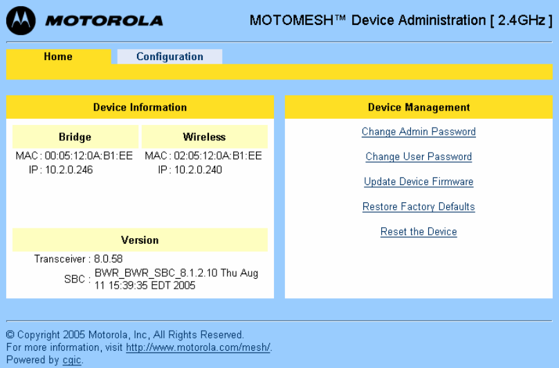
The MOTOMESH Device Administration home page provides you with some basic information about
the device, including the IP addresses assigned to the device, the MAC addresses of the device, and the
firmware revision number.
Additional web page links are available when logging-in as an Administrator (same as Super User). In
the Device Management section of the Home tab, the Administrator can:
• Change Admin password
• Change User password (Normal User Account)
• Update Device Firmware
• Restore Factory Defaults
• Reset the Device
Figure 3-2 MOTOMESH Device Administration Home Page (Super User Login)
MOTOMESH 1.0 Mesh Wireless Router Users Guide
6881011Y53-O September 2005
3-11
Viewing the Device Administration Home Page as a Normal
User
The Device Administration home page provides the Normal User (User Account) with some basic
information about the device, including the IP addresses assigned to the device, the MAC addresses of
the device and the firmware revision.
In the Device Management section of the Home tab, the User Account (non-administrative account)
can:
• Change User password
• Reset the Device
Viewing the MWR Device Administration
Configuration Page
.............................................
.
.
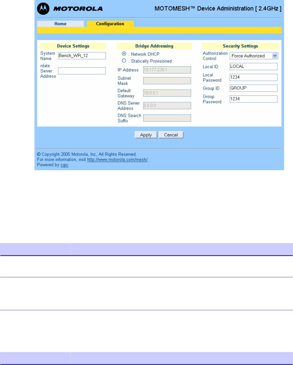
Once you have accessed the MOTOMESH Device Administration home page, click on the
Configuration tab to display the IP address configuration.
The MOTOMESH Device Administration Configuration page when viewed as an Administrator (same
as Super User Login) allows for changes to the device configuration.
Please note that the default Bridge Addressing scheme is set to Network DHCP and selecting the
Statically Provisioned mode will allow for field entry into the previously inactive (grayed-out) fields
in that section of the web page.
When making changes to the Bridge Addressing section be sure to select the Apply button to initiate
the changes and then follow on-screen prompts to complete the process.
Chapter 3: Device Configuration
6881011Y53-O September 2005
3-12
Figure 3-3 MOTOMESH Device Administration Configuration Page
The following sections describe the main section contents displayed in the Configuration tab of the
device administration web interface.
Device Settings Section
Table 3-2 Device Settings Section (Configuration Tab)
Field Name Field Description Field Default Value
System Name This is the name of the device as shown by
MeshManager Assigned by
Network Administrator
RDATE Server IP
Address The IP address of the RDATE server. This is usually the
MiSC when operating in infrastructure mode. The
RDATE server provides the current date to the MWR.
The MWR can operate without an RDATE server.
172.31.0.20
Bridge Addressing Section
Table 3-3 Bridge Addressing Section (Configuration Tab)
Field Name Field Description Field Default Value
Network DHCP
Or
Use this setting to decide whether the device will get its
IP address automatically from a Network DHCP server
or use a fixed address provided manually by a Network
Network DHCP

MOTOMESH 1.0 Mesh Wireless Router Users Guide
6881011Y53-O September 2005
3-13
Field Name Field Description Field Default Value
Statically Provisioned Operator (Statically provisioned).
IP Address The IP address will be automatically provided by a
DHCP server if one exists and the above field has been
set to Network DHCP. If the setting has been set as
Statically Provisioned, and not provided by the Network
Operator, then it will be automatically hashed from the
device’s MAC Address.
Varies depending on the
selection made in the
field above.
Subnet Mask This is the subnet mask for the local Ethernet segment. blank
Default Gateway The MWR will tell the attached Ethernet devices to use
this address for the default gateway, and the MWR will
use the address when accessing the local Ethernet
segment.
Assigned by
Network Administrator
DNS Server Address The address of the local DNS Server. Assigned by
Network Administrator
DNS Search Suffix The DNS search suffix provided by the Network
Administrator. blank
Additional Information about the Network DHCP Setting
Network DHCP means that the MWR device can be configured to request an address from a DHCP
server and requires the inclusion of a DHCP server in the core network configuration to answer these
requests. With Network DHCP selected, the MWR will send DHCP requests for its own address to the
core network once it becomes associated and establishes communications with the infrastructure.
Operation under the Network DHCP selection allows users to temporarily wander outside of the
network infrastructure without losing connectivity.
The server may be configured by the operator to hand out temporary or static leases. The MWR must
associate and acquire an address from the network before establishing communications. Once a lease
has been granted, the address will be valid out of network coverage for the remainder of the lease or, if
a static lease was granted, until the next power cycle. If the lease expires or the user cycles power
while outside of network coverage, the user will again lose the ability to communicate with the
wireless network.
Additional Information about the Statically Provisioned Setting
When selecting the Statically Provisioned Bridge Addressing option from the Configuration web
page, the MWR device will use provisioned DHCP-like information to establish an IP address for use
in the wireless network. A DHCP server is not required on the core network because the addresses are
derived from the MAC address by default. It should be noted that a DHCP server can still exist on the
network to hand out addresses to other nodes using the Network DHCP option as long as the server's
address range does not conflict with addresses assigned to other devices using the Statically
Provisioned option.
The IP addresses and options used are also configurable per-device using the MOTOMESH
MeshManager application.

Chapter 3: Device Configuration
6881011Y53-O September 2005
3-14
The Network Operator can choose to keep the provided (derived IP address) or assign a fixed IP
address and subnet mask. It is up to the Network Operator to ensure that the assigned address is
routable on the core network (if core network access is needed) and that it does not conflict with other
addresses in use. This is analogous to and carries the same caveats as plugging an Ethernet card into a
LAN and manually assigning an address to the card.
Security Settings Section (Authentication)
There are three security authentication settings available to the MOTOMESH MWR device: Force
Authorized, Force Unauthorized, and Local. Security authentication modes are selected from within
the Security Settings section of the MOTOMESH Device Administration Configuration page in the
Authorization Control field
The table below describes each field within the Security Settings section.
Table 3-4 Device Web Interface - Security Settings Section (Configuration Tab)
Field Name Field Description Field Default
Value
To allow for various levels of security and authentication control, there are
three security authentication settings available to the MOTOMESH MWR
device: Force Authorized, Force Unauthorized, and Local.
Force Authorized:
In Force Authorized mode, there are effectively no security and
authentication controls, resulting in open authentication for all network
devices. There will be no security measures applied to links between
devices that are currently set to Force Authorized. Hardware
authentication via the HAS is still performed but password authentication
is not carried out at the user level and there is no integrity check carried out
for all packets transferred between any source and destination node
Force Unauthorized:
In Force Unauthorized mode, all devices seeking authorization for network
access will be denied, effectively locking down the network. The Force
Unauthorized setting will not allow any network device to establish
communication with any other node that may attempt to communicate with
the node set to Force Unauthorized.
Authorization
Control
Local:
In Local mode, the User ID and password for all devices requesting
network access must be validated against the security information
configured at the IAP. If the password is not valid, access will be denied. If
the password is valid, the device will be authorized for network access and
a secure connection will be maintained for the duration of the association
with the IAP. Integrity checking will be carried out on all the packets
flowing between the source and destination node.
Force Authorized
Local ID The specified Local ID is used for communication authentication with an
Intelligent Access Point device (IAP). Local
Local
Password The password used for authentication control between a local subscriber
device and an IAP device. blank
MOTOMESH 1.0 Mesh Wireless Router Users Guide
6881011Y53-O September 2005
3-15
Field Name Field Description Field Default
Value
Group ID The specified Group ID is used for authentication control between local
subscriber devices when communicating in peer-to-peer mode. Group
Group
Password The password used between local subscriber devices that belong to the
same assigned group and share the same password. blank
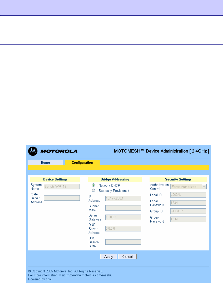
Viewing the MWR Configuration Page as a Normal User
When a Normal User logs into the Device Administration web interface, the Configuration page
contents will be the same as when viewed by an administrator account. The only difference is that
Normal users can ONLY change the Bridge Addressing scheme to Statically Provisioned and enter
specific IP addresses if needed or requested by a Network Administrator.
Please note that the default addressing scheme is set to Network DHCP and selecting the Statically
Provisioned mode will allow for field entry into the previously inactive (grayed-out) fields in that
section of the web page.
When making changes to the Bridge Addressing section be sure to select the Apply button to initiate
the changes and then follow on-screen prompts to complete the process.
Figure 3-4 MWR Configuration Page (Normal User Account)
6881011Y53-O September 2005
4-1
Chapter
4
Chapter 4: Device Maintenance
.............................................
.
.
.
.
This chapter describes the available device maintenance functions through the use of the MWRs local
web interface.
Changing the Web Interface Password
.............................................
.
.
For security reasons it is important to change the Administration password at your earliest
convenience. To change an Administration or User Password, select the Change Admin Password or
the Change User Password option from the MWR Device Administration Home Page. The device will
present the following web page.
Figure 4-1 Select Change Admin Password
The new password will be stored in flash, and the device will present a status screen indicating that the
change was successful.
Chapter 4: Device Maintenance
6881011Y53-O September 2005
4-2
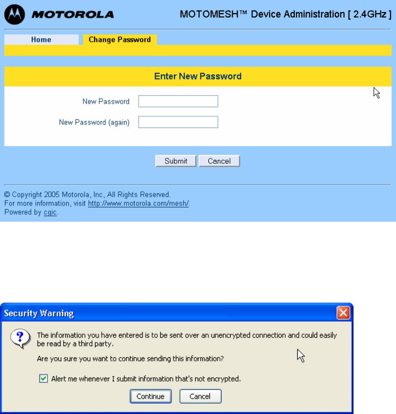
Figure 4-2 Enter New Password Screen
Enter a new password for the web administrator account and click on the Submit button.
After the new password entry has been submitted, the device will prompt the operator to Continue
with the process.
Figure 4-3 Password Changed Confirmation
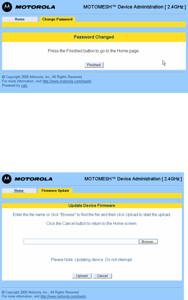
From the Password Changed screen select the Finished button to return to Home page.
MOTOMESH 1.0 Mesh Wireless Router Users Guide
6881011Y53-O September 2005
4-3
Figure 4-4 Password Change Completed
Updating the Device Firmware
.............................................
.
.
The web interface for the device also provides the ability to update the firmware on-site. To use this
feature, you must have an upgrade file from a released upgrade package.
When the Update Device Firmware function is selected from the MOTOMESH Device Administration
home page, the device will present the following web page:
Figure 4-5 Update Device Firmware Web Page
Chapter 4: Device Maintenance
6881011Y53-O September 2005
4-4
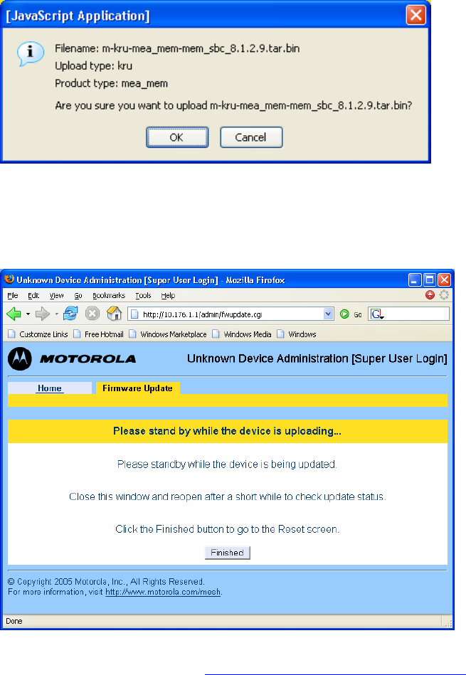
Entered the correct filename and select the Upload button to initiate the device firmware update.
When the device will prompt for firmware filename selection confirmation, select the OK button to
continue with the update process. The filename shown in the figure below is only an example; the
actual file name will be different.
Figure 4-6 Confirm Upload Window for Firmware Update
When the filename has been confirmed, the web browser will transmit the file to the device, and the
device will present an upgrade progress screen. This page will indicate the current stage in the upgrade
process.
Figure 4-7 Firmware Upload Progress Web Page
Once the upgrade is completed, the device must be reset. The Finished button will transition the web
browser to the reset screen. See the Resetting the MWR via the Device Web Page section in this
manual for additional information.
Resetting the MWR via the Device Web Page
.............................................
.
MOTOMESH 1.0 Mesh Wireless Router Users Guide
6881011Y53-O September 2005
4-5
.
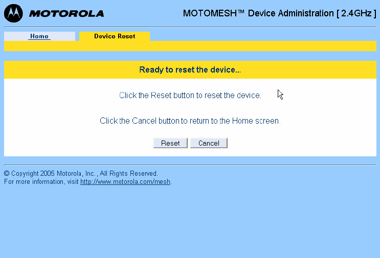
Although you should not have to reset the MWR device, the device can be reset via the device
administration web interface. In order to reset the device, return to the MOTOMESH Device
Administration Home page, and choose the Reset the Device selection.
The web page displayed will allow you to reset the device. Select the Reset button to initiate the reset
process.
Figure 4-8 Device Reset Prompt Web Page
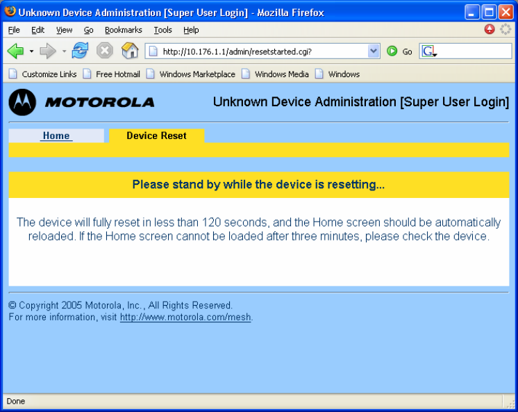
When you have reset the device, the following screen will be displayed. Your browser will delay for a
short time, then transition to the home page once more.
Chapter 4: Device Maintenance
6881011Y53-O September 2005
4-6
Figure 4-9 Device Reset in Progress Page
NOTE: After the completion of the reset, you may experience a slight delay when bringing up another
web page. Be patient.
Restoring Factory Settings
.............................................
.
.
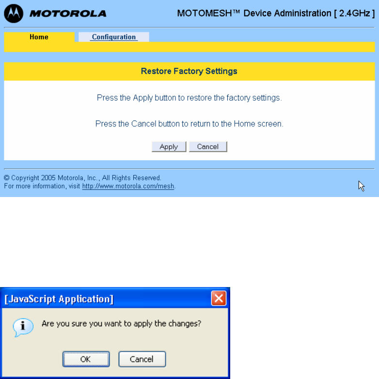
When the Restore Factory Defaults function is selected from the MWR Device Administration Home
Page, the device will present the following web page.
Select the Apply button to initiate restoring the factory settings on the device.
MOTOMESH 1.0 Mesh Wireless Router Users Guide
6881011Y53-O September 2005
4-7
Figure 4-10 Restore Factory Settings Web Page
The Restore Factory Defaults function will allow you to return the device to factory defaults. This
change will include the web password for the administrator and access accounts. This will also return
the local IP addresses to the default MAC-derived values.
The confirmation window will be displayed. Click on the OK button to confirm the action.
Figure 4-11 Confirm Changes Window for Restore Factory Settings
Chapter 4: Device Maintenance
6881011Y53-O September 2005
4-8
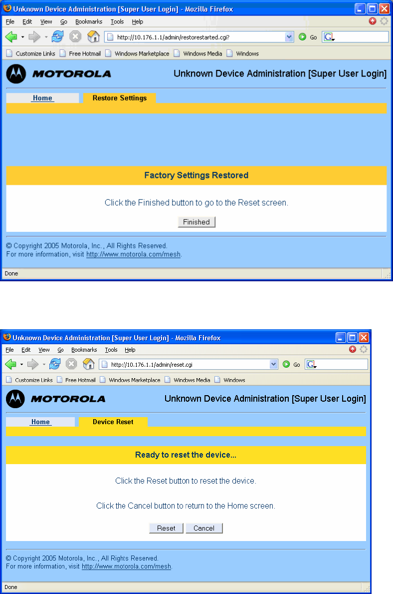
Figure 4-12 Factory Settings Restored Web Page
Click on the Finished button to continue to the Reset page.
Figure 4-13 Ready to Reset Device Web Page
Select the Reset button to initiate resetting the device.
MOTOMESH 1.0 Mesh Wireless Router Users Guide
6881011Y53-O September 2005
4-9
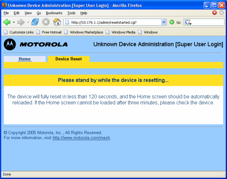
Figure 4-14 Resetting Device Web Page
When the device has finished resetting, the web page will update to the Device Administration Home
page.
Chapter 4: Device Maintenance
6881011Y53-O September 2005
4-10
This page intentionally left blank.

6881011Y53-O September 2005
5-1
Chapter
5
Chapter 5: Customer Information
.............................................
.
.
.
.
This chapter provides information about how to obtain customer service support from Motorola and
describes the type of information you should have available prior to making the support call.
Customer Service Information
.............................................
.
.
If you have read this document and made every effort to resolve installation or operation issues
yourself and still require help, please contact Motorola System Support Center (SSC) using the
following contact information:
Hours of Operation
7 days a week, 24 hours
Technical Support: 800-221-7144 (USA)
Obtaining Support
Motorola provides technical support services for your system and recommends that you coordinate
warranty and repair activities through the Motorola System Support Center (SSC). When you consult
the Motorola SSC, you increase the likelihood that problems are rectified in a timely fashion and that
warranty requirements are satisfied. Check your contract for specific warranty and service information.
System Information
To be provided with the best possible opportunity for support, collect the following system information
and have it available when obtaining support.
• Location of the system
• Date the system was put into service
Chapter 5: Customer Information
6881011Y53-O September 2005
5-2
• Software or firmware version information for components of your system
• Serial number(s) of the device(s) or component(s) requiring support
• A written description of the symptom or observation of the problem:
- When did it first appear?
- Can it be reproduced?
- What is the step-by-step procedure to cause it?
• Do other circumstances contribute to the problem? For example, changes in weather or
other conditions?
• Maintenance action preceding problem:
- Upgrade of software or equipment
- Change in the hardware or software configuration
- Software reload - from backup or from CD-ROM (note the version and date)
Return Material Request
After collecting system information, contact the Motorola System Support Center for assistance or to
obtain a Return Material Authorization (RMA) number for faulty Field Replaceable Entities (FREs):
North America: 800-221-7144
Radio Products and Services Division
The Radio Products and Services Division is your source for manuals and replacement parts.
Radio Products and Services Division Telephone Numbers
The telephone numbers for ordering are: (800)-422-4210 (US and Canada orders)
The fax numbers are: (800)-622–6210 (US and Canada orders)
The number for help identifying an item or part number is (800)-422-4210; select choice “3” from the
menu
Returning System Components to Motorola
Motorola's service philosophy is based on field replaceable entities (FREs). FREs are system
components identified by Motorola to be returned to Motorola for repair. In turn, Motorola sends you a
replacement FRE component to help you maintain maximum operating performance for your system.
Returning FREs
Return faulty FREs to Motorola for repair. When you return an assembly for service, follow these best
practices:
MOTOMESH 1.0 Mesh Wireless Router Users Guide
6881011Y53-O September 2005
5-3
• Place any assembly containing CMOS devices in a static-proof bag or container for
shipment.
• Obtain a return authorization (RA) number from the Motorola System Support Center.
• Include the warranty, model, kit numbers, and serial numbers on the job ticket, as
necessary.
• If the warranty is out of date, you must have a purchase order.
• Print the return address clearly, in block letters.
• Provide a phone number where your repair technician can be reached.
• Include the contact person's name for return.
• Pack the assembly tightly and securely, preferably in its original shipping container.

6881011Y53-O September 2005
6-1
Chapter
6
Chapter 6: Certification and Safety
Information
.............................................
.
.
.
.
This chapter lists the relevant FCC Certification and Product Safety Information for the MOTOMESH
devices described in this manual.
FCC Regulatory Information
This device complies with Part 15 of the FCC Rules. Operation is subject to the following two
conditions: (1) this device may not cause harmful interference, and (2) this device must accept any
interference received; including interference that may cause undesired operation.
The MWR7300 requires professional installation to ensure the installation is performed in accordance
with FCC licensing regulations.
Federal Communications Commission (FCC) Statement:
This equipment has been tested and found to comply with the limits for a Class A digital device,
pursuant to part 15 of the FCC Rules. These limits are designed to provide reasonable protection
against harmful interference when the equipment is operated in a commercial environment. This
equipment generates, uses, and can radiate radio frequency energy and, if not installed and used in
accordance with the instruction manual, may cause harmful interference to radio communications.
Operation of this equipment in a residential area is likely to cause harmful interference in which case
the user will be required to correct the interference at his own expense.
Any changes or modifications not expressly approved by Motorola could void the user’s authority to
operate the equipment.
FCC RF Radiation Exposure Statement
This equipment complies with FCC radiation exposure limits set forth for an uncontrolled
environment. This equipment should be installed and operated with minimum distance 2 meters
between the radiator and your body.
Chapter 6: Certification and Safety Information
6881011Y53-O September 2005
6-2
Safety Information for the MOTOMESH Products
The Federal Communications Commission (FCC) with its action in ET Docket 96-8 has adopted a
safety standard for human exposure to radio frequency (RF) electromagnetic energy emitted by FCC
certified equipment. Motorola MOTOMESH products meet the uncontrolled environmental limits
found in OET-65 and ANSI C95.1, 1991. Proper operation of this radio according to the instructions
found in this manual and the hardware and software guides on the MOTOMESH CD will result in user
exposure that is substantially below the FCC recommended limits.
• Do not touch or move the antenna(s) while the unit is transmitting or receiving.
• Do not hold any component containing a radio such that the antenna is very close to or
touching any exposed parts of the body, especially the face or eyes, while transmitting.
• Do not operate a portable transmitter near unshielded blasting caps or in an explosive
environment unless it is a type especially qualified for such use.
• Do not operate the radio or attempt to transmit data unless the antenna is connected;
otherwise, the radio may be damaged.
Safety Certification
Conforms to UL STD ANSI/UL 60950 3rd Edition
Certified to CAN/CSA C22.2 NO. 60950-00
Equipment shall be suitable for use in Air pressure: 86kPa to106kPa.

MOTOMESH 1.0 Mesh Wireless Router Users Guide
6881011Y53-O September 2005
Index-1
Index
Index
.............................................
.
.
.
.
A
antenna, 6-2
C
Copyrights, iii
D
DHCP server, 3-13
Disclaimer, iii
M
MAC addresses, 3-10, 3-11
R
RDATE Server, 3-12
S
SBC, 3-8
subnet, 3-13, 3-14
T
Trademarks, iii
V
VMM, 3-9, 4-1
Chapter 6: Certification and Safety Information
6881011Y53-O September 2005
Index-2

6881011Y53-O September 2005
Glossary-1
Glossary
Glossary
.............................................
.
.
.
IAP – Intelligent Access Point
MEA – Mesh Enabled Architecture
MiSC – Mobile Internet Switching Controller
SBC – Single Board Computer
SD – Subscriber Device, a general description to a device type that is usually a WMC or
a MWR.
MWR– Vehicle Mounted Modem
WMC – Wireless Modem Card, can apply to any model number
WR – Wireless Router