Zebra Technologies AP7131 WLAN a/b/g/n Access Point Module User Manual 72 70931 01
Zebra Technologies Corporation WLAN a/b/g/n Access Point Module 72 70931 01
Contents
- 1. User Manual
- 2. user manual
- 3. UZ7AP7131 User Manual
User Manual
INSTALLATION
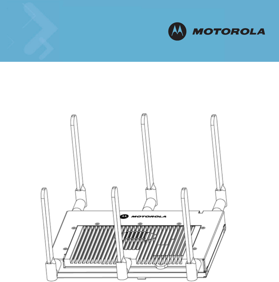
AP-7131 Access Point
Installation Guide

1.0 Introduction . . . . . . . . . . . . . . . . . . . . . . . . . . . . . . . . . . . . . . . . . .1
1.1 Document Conventions . . . . . . . . . . . . . . . . . . . . . . . . . . . . . . . . . .1
1.2 Warnings . . . . . . . . . . . . . . . . . . . . . . . . . . . . . . . . . . . . . . . . . . . . .2
1.3 Site Preparation . . . . . . . . . . . . . . . . . . . . . . . . . . . . . . . . . . . . . . . .2
2.0 Hardware Installation . . . . . . . . . . . . . . . . . . . . . . . . . . . . . . . . .3
2.1 Precautions . . . . . . . . . . . . . . . . . . . . . . . . . . . . . . . . . . . . . . . . . . . .3
2.2 Package Contents . . . . . . . . . . . . . . . . . . . . . . . . . . . . . . . . . . . . . .3
2.3 AP-7131 Placement . . . . . . . . . . . . . . . . . . . . . . . . . . . . . . . . . . . . .4
2.4 Mounting the AP-7131 . . . . . . . . . . . . . . . . . . . . . . . . . . . . . . . . . .9
2.5 LED Indicators . . . . . . . . . . . . . . . . . . . . . . . . . . . . . . . . . . . . . . . .19
3.0 Basic AP-7131 Configuration . . . . . . . . . . . . . . . . . . . . . . . . . .21
3.1 Resetting the AP-7131 Password. . . . . . . . . . . . . . . . . . . . . . . . . .23
3.2 Configuring "Basic" Device Settings . . . . . . . . . . . . . . . . . . . . . . .24
3.3 Where to Go From Here? . . . . . . . . . . . . . . . . . . . . . . . . . . . . . . . .32
Contents

4.0 Regulatory Compliance . . . . . . . . . . . . . . . . . . . . . . . . . . . . . . . 33
5.0 Waste Electrical and Electronic Equipment (WEEE) . . . . . . 38
6.0 Motorola’s Enterprise Mobility Support Center . . . . . . . . . . 40

v
MOTOROLA and the Stylized M Logo are registered in the US Patent &
Trademark Office. Symbol is a registered trademark of Symbol Technologies,
Inc. All other product or service names are the property of their respective
owners. © Motorola, Inc. 2008. All rights reserved.

Introduction 1
1 Introduction
As a standalone access point, the AP-7131 provides small and medium-sized businesses with a
consolidated wired and wireless networking infrastructure, all in a single device. The integrated
router, gateway, firewall, DHCP and AAA Radius servers, VPN, hot-spot gateway and Power-over-
Ethernet (PoE) simplify and reduce the costs associated with networking by eliminating the need to
purchase and manage multiple pieces of equipment.
The AP-7131 is also designed to meet the needs of large, distributed enterprises by converging the
functionality of a thick access point and thin access port into a single device. This mode enables the
deployment of a fully featured intelligent access point that can be centrally configured and managed
via a Motorola wireless switch in either corporate headquarters or a network operations center
(NOC). In the event the connection between the AP-7131 and the wireless switch is lost, a Remote
Site Survivability (RSS) feature ensures the delivery of uninterrupted wireless services at the local or
remote site. All traffic between the adaptive access points and the wireless switch is secured though
an IPSec tunnel. Additionally, compatibility with Motorola’s RF Management Suite allows you to
centrally plan, deploy, monitor, and secure large AP-7131 deployments.
If new to the AP-7131 and access point technology, refer to the AP-7131 Product Reference Guide to
familiarize yourself with access point technology and the feature set exclusive to the Motorola
AP-7131. The guide is available, at http://support.symbol.com/support/product/manuals.do.
1.1 Document Conventions
The following graphical alerts are used in this document to indicate notable situations:
NOTE Tips, hints, or special requirements that you should take note of.
CAUTION Care is required. Disregarding a caution can result in data loss or
equipment malfunction.
WARNING! Indicates a condition or procedure that could result in personal injury or
equipment damage.
!

AP-7131 Access Point: Installation Guide
2
1.2 Warnings
•Read all installation instructions and site survey reports, and verify correct equipment installation before
connecting the AP-7131 to its power source.
•Remove jewelry and watches before installing this equipment.
•Verify that the unit is grounded before connecting it to the power source.
•Verify that any device connected to this unit is properly wired and grounded.
•Connect all power cords to a properly wired and grounded electrical circuit.
•Verify that the electrical circuits have appropriate overload protection.
•Attach only approved power cords to the device.
•Verify that the power connector and socket are accessible at all times during the operation of the
equipment.
•Do not work with power circuits in dimly lit spaces.
•Do not install this equipment or work with its power circuits during thunderstorms or other weather
conditions that could cause a power surge.
•Verify there is adequate ventilation around the device, and that ambient temperatures meet equipment
operation specifications.
1.3 Site Preparation
•Consult your site survey and network analysis reports to determine specific equipment placement, power
drops, and so on.
•Assign installation responsibility to the appropriate personnel.
•Identify and document where all installed components are located.
•Provide a sufficient number of power drops for your equipment.
•Ensure adequate, dust-free ventilation to all installed equipment.
•Identify and prepare Ethernet and console port connections.
•Verify that cable lengths are within the maximum allowable distances for optimal signal transmission.
Hardware Installation 3
2 Hardware Installation
An AP-7131 installation includes mounting the AP-7131 on a wall, ceiling T-bar or an above the ceiling
orientation, connecting the AP-7131 to the network (LAN or WAN port connection), connecting
antennas and applying power. Installation procedures vary for different environments.
An AP-7131 model access point has the following port designations:
• GE1/POE - LAN port
• GE2 - WAN Port
2.1 Precautions
Before installing the AP-7131 verify the following:
• Do not install in wet or dusty areas without additional protection. Contact a Motorola
representative for more information.
• Verify the environment has a continuous temperature range between -20° C to 50° C.
2.2 Package Contents
Check package contents for the correct model AP-7131 and applicable AP-7131 accessories. Each
available configuration (at a minimum), contains:
• AP-7131 model access point (accessories dependent on SKU ordered)
• AP-7131 Install Guide (this guide)
• Accessories Bag (4 rubber feet and a LED light pipe and badge with label for above the
ceiling installations)
Contact the Motorola Support Center to report missing or improperly functioning items.
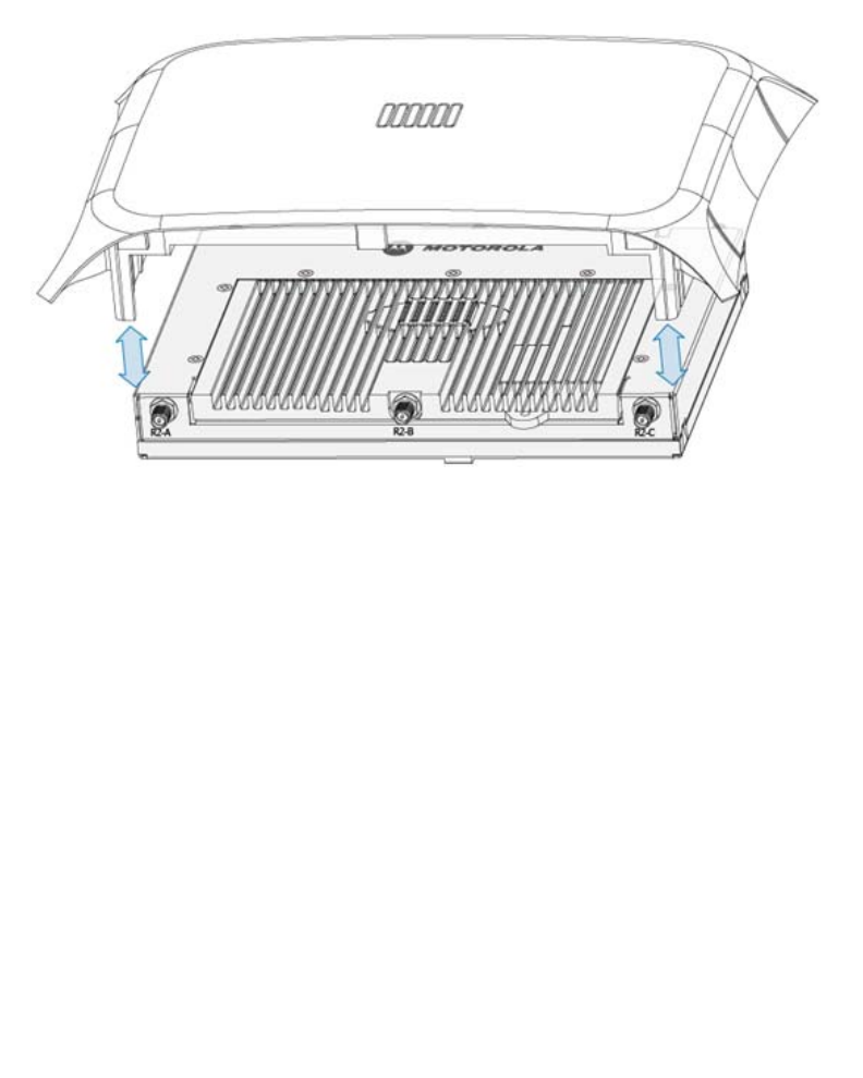
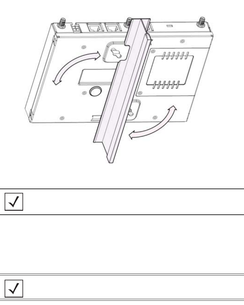
NOTE The AP-7131 ships with a cover (facade) to protect the access point. The
cover disconnects from the access point as illustrated on the next page.
When attached, the AP-7131’s LEDs continue to illuminate through the
cover.
AP-7131 Access Point: Installation Guide
4
2.3 AP-7131 Placement
For optimal performance, install the AP-7131 away from transformers, heavy-duty motors, fluorescent
lights, microwave ovens, refrigerators and other industrial equipment. Signal loss can occur when
metal, concrete, walls or floors block transmission. Install the AP-7131 in open areas or add access
points as needed to improve coverage.
Place the AP-7131 using the following guidelines:
• Install the AP-7131 at an ideal height of 10 feet from the ground.
• Orient the AP-7131 antenna vertically for best reception.
• Point the AP-7131 antenna(s) downward if attaching to the ceiling.
Motorola recommends conducting a site survey to define and document radio interference obstacles
before installing the AP-7131 to maximize its radio coverage area.
Hardware Installation 5
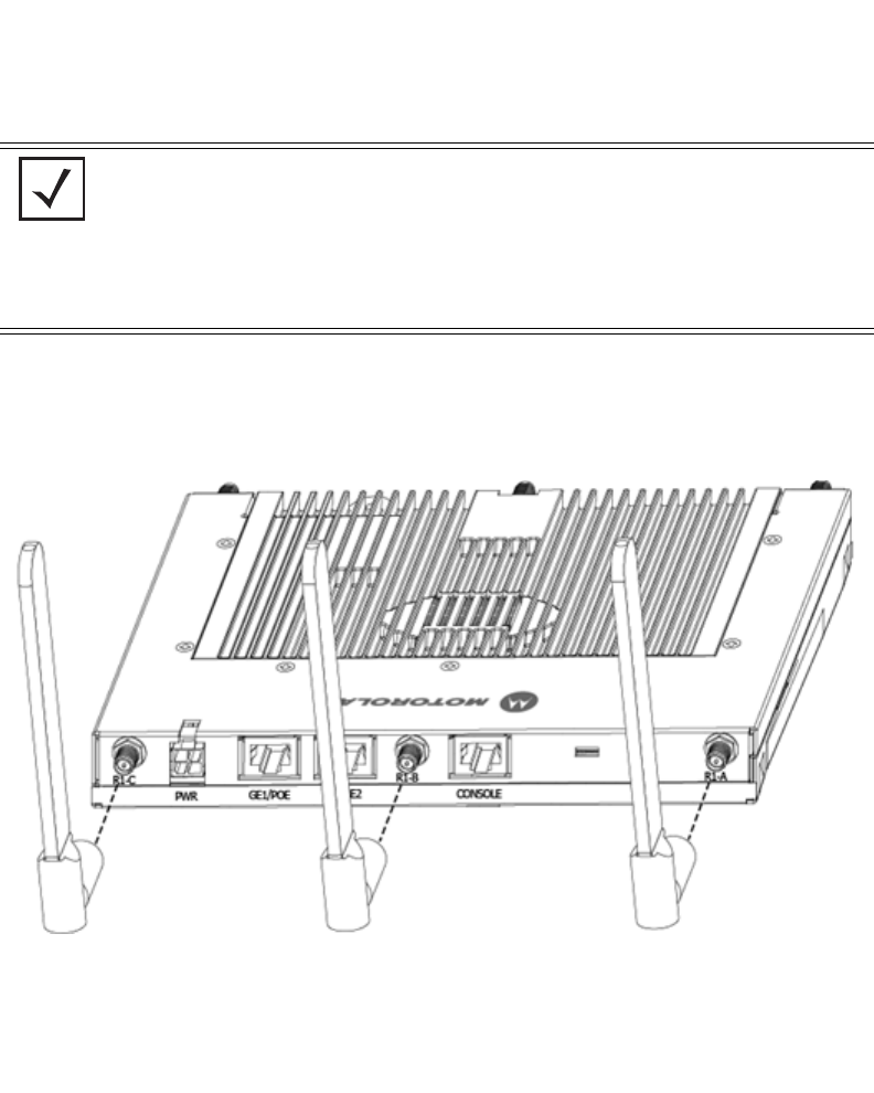
2.3.1 AP-7131 Antenna Options
Motorola supports two antenna suites for the AP-7131. One antenna suite supporting the 2.4 GHz
band and another antenna suite supporting the 5.2 GHz band. Select an antenna model best suited
to the intended operational environment of your AP-7131.
Antenna connectors for Radio 1 are located in a different location from the Radio 2 antenna
connectors. On single radio versions, the R-SMA connectors can support both bands and should be
connected to a R-SMA dual-band antenna or an appropriate single band antenna. If necessary a
R-SMA to R-BNC adapter (Part No. 25-72178-01) can be purchased separately from Motorola.
Certain Rogue AP Detection and Intrusion Detection features use an AP-7131 radio to perform
dual-band scanning. The dedicated radio should be connected to an appropriate dual-band dipole
antenna (Part No. ML-2452-APA2-01).
NOTE On a single-radio AP-7131, Radio 1 can be configured to be either a 2.4
GHz or 5.2 GHz radio. On a dual-radio model, Radio 1 refers to the
AP-7131’s 2.4 GHz radio and Radio 2 refers to the AP-7131 5.2 GHz radio.
However, there could be some cases where a dual-radio AP-7131 is
performing a Rogue AP detector function. In this scenario, the AP-7131 is
receiving in either 2.4 GHz or 5.2 GHz over the Radio 1 or Radio 2
antennas depending on which radio is selected for the scan.
AP-7131 Access Point: Installation Guide
6
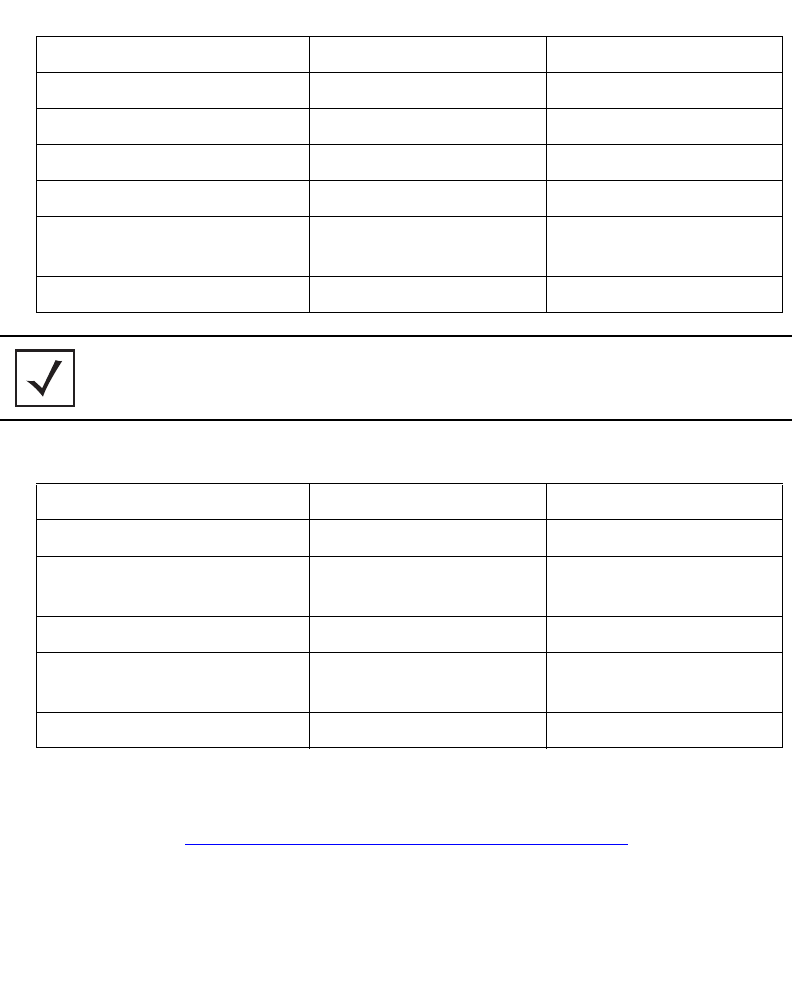
The 2.4 GHz antenna suite includes the following models:
The 5.2 GHz antenna suite includes the following models:
For detailed specifications on the antennas available to the AP-7131, refer to the
AP-7131 Product Reference Guide or the Enterprise Wireless LAN Antenna Specification Guide. Both
guides are available at http://support.symbol.com/support/product/manuals.do.
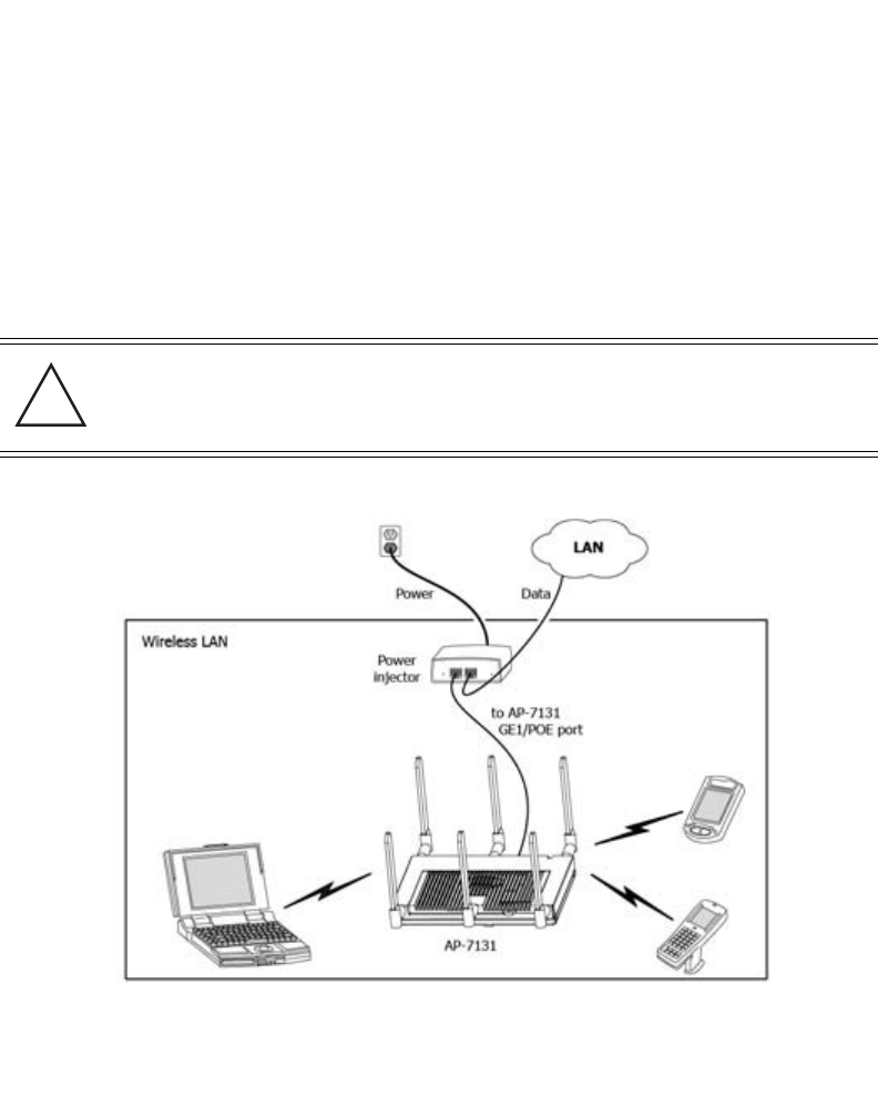
2.3.2 Power Injector System
An AP-7131 receives power directly form a 48V AC-DC power supply (Part No. 50-14000-247R) or via
an Ethernet cable connected to the GE1/POE port.
Part Number Antenna Type Nominal Net Gain (dBi)
ML-2499-11PNA2-01R Wide Angle Directional 8.5
ML-2499-HPA3-01R Omni-Directional Antenna 3.3
ML-2499-BYGA2-01R Yagi Antenna 13.9
ML-2452-APA2-01 Dual-Band 3.0
ML-2452-PTA2M3X3-1 Facade with 6 Element
Antenna Module
2.0
ML-2452-PTA3M3-036 3 Port MIMO Antenna 3.0
NOTE An additional adapter is required to use ML-2499-11PNA2-01R and
ML-2499-BYGA2-01R model antennas. Please contact Motorola for more
information.
Part Number Antenna Type Nominal Net Gain (dBi)
ML-5299-WPNA1-01R Panel Antenna 13.0
ML-5299-HPA1-01R Wide-Band Omni-Directional
Antenna
5.0
ML-2452-APA2-01 Dual-Band 4.0
ML-2452-PTA2M3X3-1 Facade with 6 Element
Antenna Module
2.0
ML-2452-PTA3M3-036 3 Port MIMO Antenna 3.0
Hardware Installation 7
When users purchase a Motorola WLAN solution, they often need to place access points in obscure
locations. In the past, a dedicated power source was required for each access point in addition to the
Ethernet infrastructure. This often required an electrical contractor to install power drops at each
access point location. An approved power injector solution merges power and Ethernet into one
cable, reducing the burden of installation and allows optimal AP-7131 placement in respect to the
intended radio coverage area.
The Power Injector is included in certain AP-7131 product SKUs. The Power Injector
(Part No. AP-PSBIAS-1P3-AFR) is a high power POE Injector delivering up to 30 watts.
The Motorola AP-7131 Power Supply (Part No. 50-14000-247R) is not included with the AP-7131 and
is orderable separately as an accessory.
A separate Power Injector is required for each AP-7131 comprising the network.
The Power Injector can be installed free standing, on an even horizontal surface or wall mounted
using the power injector’s wall mounting key holes. The following guidelines should be adhered to
before cabling the Power Injector to an Ethernet source and an AP-7131:
CAUTION The AP-7131 supports any standards-based 802.3af high power
complaint power source. However, using the wrong solution (including
a POE system used on a legacy Motorola access point) could severely
damage the AP-7131 and void the product warranty.
!

AP-7131 Access Point: Installation Guide
8
• Do not block or cover airflow to the Power Injector.
• Keep the Power Injector away from excessive heat, humidity, vibration and dust.
• The Power Injector isn’t a repeater, and does not amplify the Ethernet signal. For optimal
performance, ensure the Power Injector is placed as close as possible to the data port.
To install the Power Injector to an Ethernet data source and AP-7131:
1. Connect the Power Injector to an AC outlet (110VAC to 220VAC).
2. Connect an RJ-45 Ethernet cable between the network data supply (host) and the Power
Injector Data In connector.
3. Connect an RJ-45 Ethernet cable between the Power Injector Data & Power Out connector
and the AP-7131 GE1/POE port.
Ensure the cable length from the Ethernet source (host) to the Power Injector and AP-7131
does not exceed 100 meters (333 ft).
CAUTION Ensure AC power is supplied to the Power Injector using an AC cable
with an appropriate ground connection approved for the country of
operation.
NOTE Cabling the Power Injector to the AP-7131’s WAN port renders the
AP-7131 non-operational. Only use a AP-PSBIAS-1P3-AFR model Power
Injector with the AP-7131’s GE1/POE (LAN) port.
!
Hardware Installation 9
The Power Injector has no On/Off power switch. The Power Injector receives power and is
ready for AP-7131 device connection and operation as soon as AC power is applied.
The Power Injector demonstrates the following LED behavior under normal and/or problematic
operating conditions:
2.4 Mounting the AP-7131
The AP-7131 can attach to a wall, mount under a suspended T-Bar or above a ceiling (plenum or
attic). Choose one of the following mounting options based on the physical environment of the
coverage area. Do not mount the AP-7131 in a location that has not been approved in a site survey.
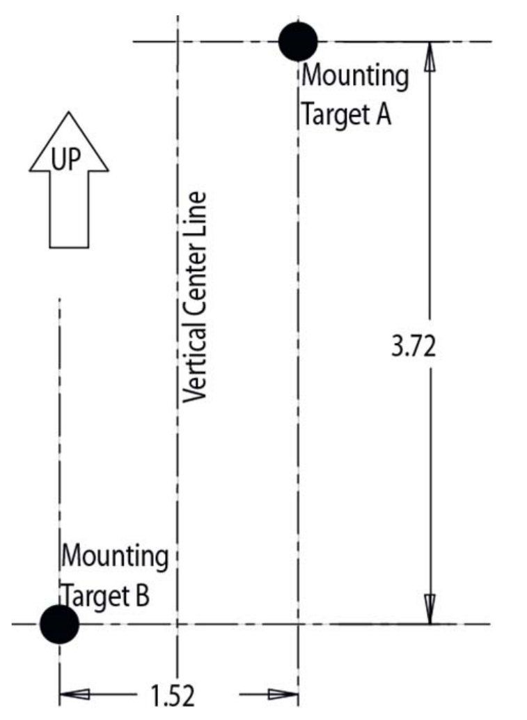
2.4.1 Wall Mounting
Wall mounting requires hanging the AP-7131 along its width (or length) using the pair of slots on the
bottom of the unit and using the AP-7131 itself as a mounting template for the screws.
The hardware and tools (customer provided) required to install the AP-7131 on a wall consists of:
• Two Phillips pan head self-tapping screws
(ANSI Standard) #6-18 X 0.875in. Type A or AB Self-Tapping screw, or
(ANSI Standard Metric) M3.5 X 0.6 X 20mm Type D Self-Tapping screw
• Two wall anchors
• Wall mount template (included on the next page)
• Security cable (optional)
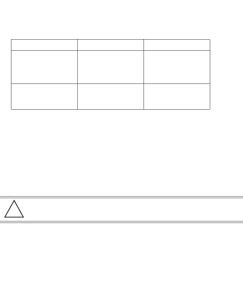
LED AC (Main) Port
Green (Steady) Power Injector is receiving
power from AC outlet
Indicates a device is
connected to the
Power Injector’s outgoing
Data & Power cable
Green (Blinking) Output voltage source is out
of range
The Power Injector is
overloaded or has a
short circuit
CAUTION An AP-7131 should be wall mounted to concrete or plaster-wall-board
(dry wall) only. Do not wall mount an AP-7131 to combustible
surfaces.
!
AP-7131 Access Point: Installation Guide
10
Hardware Installation 11
To mount the AP-7131 on a wall using the provided template:
1. Xerox copy the template (on the previous page) to a blank piece of paper. Do not reduce or
enlarge the scale of the template.
2. Tape the template to the wall mounting surface.
• If the installation requires the antenna be positioned vertically, the centerline reference
(of the template) needs to be positioned vertically. The cabling shall exit the access
point in a vertical direction.
• If the installation requires the antenna be positioned horizontally, the vertical centerline
(of the template) needs to be positioned horizontally. The cabling shall exit the access
point in a horizontal direction.
3. At mounting targets A and B, mark the mounting surface through the template at the target
center.
4. Discard the mounting template.
5. At each point, drill a hole in the wall, insert an anchor, screw into the anchor the wall
mounting screw and stop when there is 1mm between the screw head and the wall.
If pre-drilling a hole, the recommended hole size is 2.8mm (0.11in.) if the screws are going
directly into the wall and 6mm (0.23in.) if wall anchors are being used.
6. If required, install and attach a security cable to the AP-7131 lock port.
7. Attach the antennas to their correct connectors.
8. For information on the antennas available to the AP-7131, see
“AP-7131 Antenna Options” on page 5.
9. Place the large center opening of each of the mount slots over the screw heads.
10. Slide the AP-7131 down along the mounting surface to hang the mount slots on the screw
heads.
CAUTION The procedure described in this section is exclusively for wall mount
installations.
CAUTION Ensure you are placing the antennas on the correct connectors
(depending on your single or dual-radio model and frequency used) to
ensure the successful operation of the AP-7131.
NOTE It is recommended the AP-7131 be mounted with the RJ45 cable
connector oriented upwards or downwards to ensure proper operation.
!
!
AP-7131 Access Point: Installation Guide
12
11. Cable the AP-7131 using either the Power Injector solution or an approved line cord and
power supply.
For Motorola Power Injector installations:
a. Connect a RJ-45 CAT 5 Ethernet cable between the network data supply (host) and the
Power Injector Data In connector.
b. Connect a RJ-45 CAT 5 Ethernet cable between the Power Injector Data & Power Out
connector and the AP-7131 GE1/POE port.
c. Ensure the cable length from the Ethernet source (host) to the Power Injector and
AP-7131 does not exceed 100 meters (333 ft). The Power Injector has no On/Off power
switch. The Power Injector receives power as soon as AC power is applied. For more
information on using the Power Injector, see “Power Injector System” on page 6.
For standard power adapter (non Power Injector) and line cord installations:
a. Connect a RJ-45 CAT 5 Ethernet cable between the network data supply (host) and the
AP-7131 GE1/POE or GE2 port.
b. Verify the power adapter is correctly rated according the country of operation.
c. Connect the power supply line cord to the power adapter.
d. Attach the power adapter cable into the power connector on the AP-7131.
e. Attach the power supply line cord to a power supply.
12. Verify the behavior of the AP-7131 LEDs. For more information, see “LED Indicators” on
page 19.
13. The AP-7131 is ready to configure. For information on basic AP-7131 device configuration,
see “Configuring “Basic” Device Settings” on page 24.
CAUTION Do not actually connect to the power source until the cabling portion
of the installation is complete.
!
Hardware Installation 13
2.4.2 Suspended Ceiling T-Bar Installations
A suspended ceiling mount requires holding the AP-7131 up against the T-bar of a suspended ceiling
grid and twisting the AP-7131 chassis onto the T-bar.
The mounting tools (customer provided) and hardware required to install the AP-7131 on a ceiling
T-bar consists of:
• Safety wire (recommended and customer supplied)
• Security cable (optional and customer supplied)
To install the AP-7131 on a ceiling T-bar:
1. Motorola recommends you loop a safety wire — with a diameter of at least 1.01 mm (.04
in.), but no more than 0.158 mm (.0625 in.) — through the tie post (above the AP-7131’s
console connector) and secure the loop.
2. If desired, install and attach a security cable to the AP-7131 lock port.
3. Attach the antennas to their correct connectors.
For information on the antennas available to the AP-7131, see
“AP-7131 Antenna Options” on page 5.
4. Cable the AP-7131 using either the Power Injector solution or an approved line cord and
power supply.
For Motorola Power Injector installations:
a. Connect a RJ-45 CAT 5 Ethernet cable between the network data supply (host) and the
Power Injector Data In connector.
b. Connect a RJ-45 CAT 5 Ethernet cable between the Power Injector Data & Power Out
connector and the AP-7131 GE1/POE port.
c. Ensure the cable length from the Ethernet source (host) to the Power Injector and
AP-7131 does not exceed 100 meters (333 ft). The Power Injector has no On/Off power
switch. The Power Injector receives power as soon as AC power is applied. For more
information, see “Power Injector System” on page 6.
For standard power adapter (non Power Injector) and line cord installations:
CAUTION Ensure you are placing the antennas on the correct connectors
(depending on your single or dual-radio model and frequency used) to
ensure the successful operation of the AP-7131.
!
AP-7131 Access Point: Installation Guide
14
a. Connect a RJ-45 Ethernet cable between the network data supply (host) and the AP-7131
GE1/POE or GE2 port.
b. Verify the power adapter is correctly rated according the country of operation.
c. Connect the power supply line cord to the power adapter.
d. Attach the power adapter cable into the power connector on the AP-7131.
e. Attach the power supply line cord to a power supply.
5. Verify the behavior of the AP-7131 LEDs. For more information, see “LED Indicators” on
page 19.
6. Align the bottom of the ceiling T-bar with the back of the AP-7131.
7. Orient the AP-7131 chassis by its length and the length of the ceiling T-bar.
8. Rotate the AP-7131 chassis 45 degrees clockwise, or about 10 o’clock.
9. Push the back of the AP-7131 chassis on to the bottom of the ceiling T-bar.
CAUTION Do not actually connect to the power source until the cabling portion
of the installation is complete.
!
Hardware Installation 15
10. Rotate the AP-7131 chassis 45 degrees counter-clockwise.
The clips click as they fasten to the T-bar.
11. The AP-7131 is ready to configure. For information on basic AP-7131 device configuration,
see “Configuring “Basic” Device Settings” on page 24.
2.4.3 Above the Ceiling (Plenum) Installations
An AP-7131 above the ceiling installation requires placing the AP-7131 above a suspended ceiling
and installing the provided light pipe under the ceiling tile for viewing the rear panel status LEDs of
the unit. An above the ceiling AP-7131 installation enables installations compliant with drop ceilings,
suspended ceilings and industry standard tiles from .625 to .75 inches thick.
NOTE If the AP-7131 is utilizing remote management antennas, a wire cover
can be used to provide a clean finished look to the installation. Contact
Motorola for more information.
NOTE The AP-7131 is Plenum rated to UL2043 and NEC1999 for above the
ceiling installations.
AP-7131 Access Point: Installation Guide
16
The mounting hardware required to install the AP-7131 above a ceiling consists of:
• Light pipe
• Badge for light pipe
• Decal for badge
• Safety wire (strongly recommended)
• Security cable (optional)
To install the AP-7131 above a ceiling:
1. If possible, remove the adjacent ceiling tile from its frame and place it aside.
2. If required, install a safety wire, between 1.5mm (.06in.) and 2.5mm (.10in.) in diameter, in
the ceiling space.
3. If required, install and attach a security cable to the AP-7131’s lock port.
4. Mark a point on the finished side of the tile where the light pipe is to be located.
5. Create a light pipe path hole in the target position on the ceiling tile.
6. Use a drill to make a hole in the tile the approximate size of the AP-7131 LED light pipe.
7. Remove the light pipe’s rubber stopper (from the AP-7131) before installing the light pipe.
CAUTION Motorola does not recommend mounting the AP-7131 directly to any
suspended ceiling tile with a thickness less than 12.7mm (0.5in.) or a
suspended ceiling tile with an unsupported span greater than 660mm
(26in.). Motorola strongly recommends fitting the AP-7131 with a
safety wire suitable for supporting the weight of the device. The
safety wire should be a standard ceiling suspension cable or
equivalent steel wire between 1.59mm (.062in.) and 2.5mm (.10in.)
in diameter.
CAUTION Motorola recommends care be taken not to damage the finished
surface of the ceiling tile when creating the light pipe hole and
installing the light pipe.
!
!
Hardware Installation 17
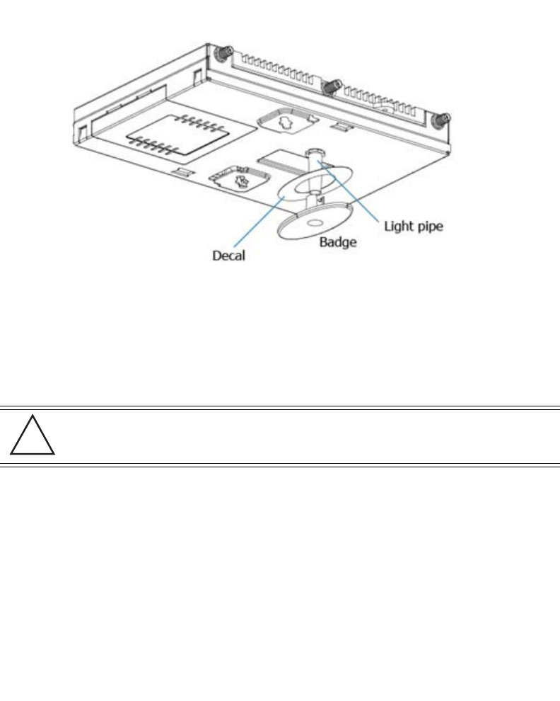
8. Connect the light pipe to the bottom of the AP-7131. Align the tabs and rotate approximately
90 degrees. Do not over tighten.
9. Fit the light pipe into hole in the tile from its unfinished side.
10. Place the decal on the back of the badge and slide the badge onto the light pipe from the
finished side of the tile.
11. Attach the antennas to their correct connectors.
For information on the antennas available to the AP-7131, see
“AP-7131 Antenna Options” on page 5.
12. Motorola recommends attaching safety wire to the AP-7131 safety wire tie point or security
cable (if used) to the AP-7131’s lock port.
13. Align the ceiling tile into its former ceiling space.
14. Cable the AP-7131 using either the Power Injector solution or an approved line cord and
power supply.
For Motorola Power Injector installations:
a. Connect a RJ-45 CAT 5 Ethernet cable between the network data supply (host) and the
Power Injector Data In connector.
b. Connect a RJ-45 CAT 5 Ethernet cable between the Power Injector Data & Power Out
connector and the AP-7131 GE1/POE port.
CAUTION Ensure you are placing the antennas on the correct connectors
(depending on your single or dual-radio model and frequency used) to
ensure the successful operation of the AP-7131.
!
AP-7131 Access Point: Installation Guide
18
c. Ensure the cable length from the Ethernet source (host) to the Power Injector and
AP-7131 does not exceed 100 meters (333 ft). The Power Injector has no On/Off power
switch. The Power Injector receives power as soon as AC power is applied. For more
information on using the Power Injector, see “Power Injector System” on page 6.
For standard power adapter (non Power Injector) and line cord installations:
a. Connect a RJ-45 Ethernet cable between the network data supply (host) and the AP-7131
GE1/POE or GE2 port.
b. Verify the power adapter is correctly rated according the country of operation.
c. Connect the power supply line cord to the power adapter.
d. Attach the power adapter cable into the power connector on the AP-7131.
e. Attach the power supply line cord to a power supply.
15. Verify the behavior of the AP-7131 LED light pipe. For more information, see
“LED Indicators” on page 19.
16. Place the ceiling tile back in its frame and verify it is secure.
17. The AP-7131 is ready to configure. For information on basic AP-7131 device configuration,
see “Configuring “Basic” Device Settings” on page 24.
CAUTION Do not actually connect to the power source until the cabling portion
of the installation is complete.
!
Hardware Installation 19
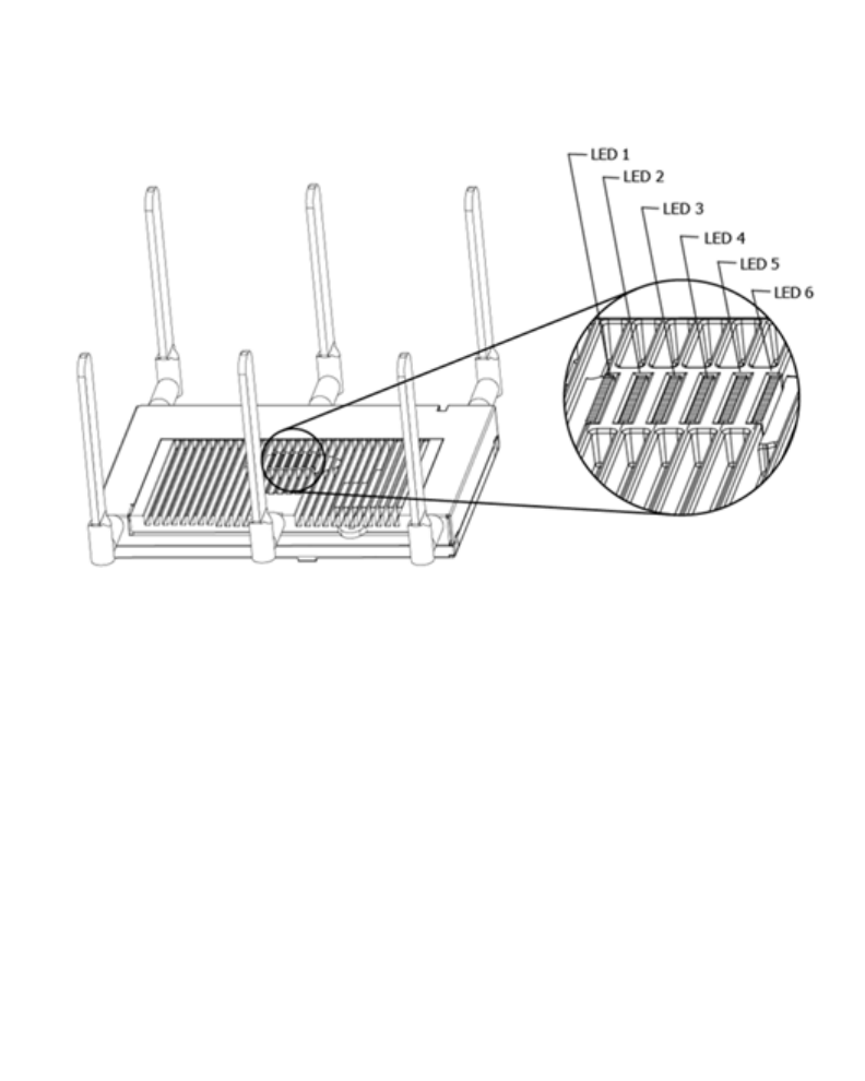
2.5 LED Indicators
Six LEDs illuminate on the front of the AP-7131 (on top of the AP-7131 housing) for dual radios models
and five illuminate for single radio models. Two LEDs (for above the ceiling installations) are located
on the back of the device.
The LEDs on the top housing of the AP-7131 are clearly visible in wall and below ceiling installations.
The top housing LEDs have the following display and functionality:
AP-7131 Access Point: Installation Guide
20
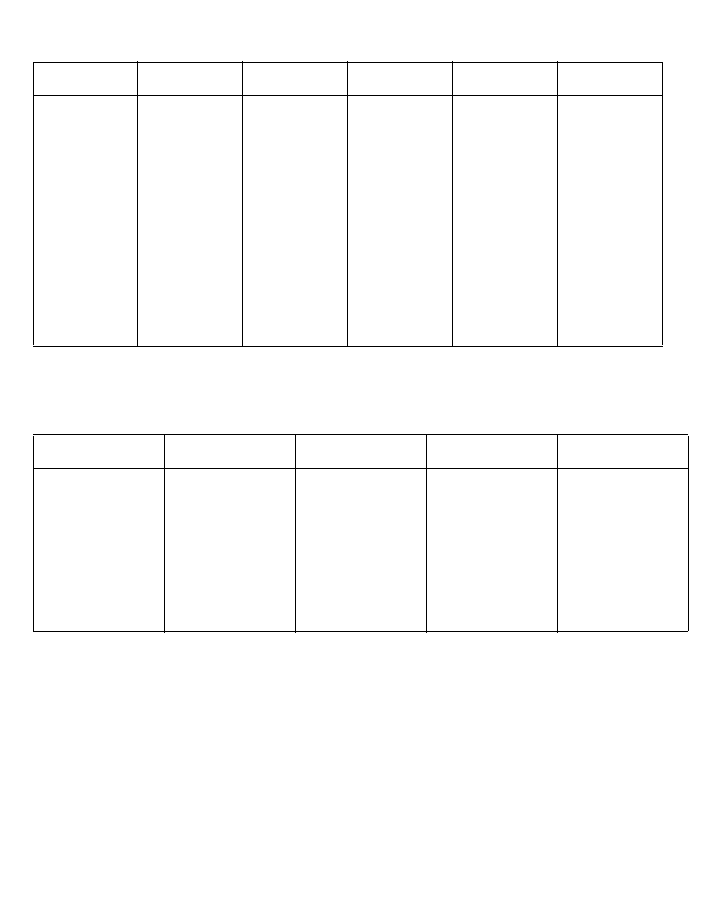
2.5.1 Dual Radio (2.4/5.2 Ghz) AP-7131 With Sensor Slot LEDs
A dual radio (2.4/5.2 Ghz) model AP-7131 has the following unique LED behavior:
2.5.2 Single Radio 2.4 Ghz AP-7131 LEDs
The single 2.4 Ghz radio model AP-7131 has the following unique LED behavior:
LED 1 LED 2 LED 3 LED 4 LED 5 LED 6
Blinking Red
indicates
booting.
Solid Red
defines a
failure
condition.
White
defines
normal
operation
Green
defines
normal GE1
operation.
Yellow
defines a
collision
Green
defines
normal GE2
operation.
Yellow
defines a
collision
Amber
defines 5.2
Ghz radio as
configured
Emerald
defines 2.4
Ghz radio as
configured
Amber
5.2 Ghz radio
as present
and scanning
Emerald
2.4 Ghz radio
as present
and scanning
LED 1 LED 2 LED 3 LED 4 LED 5
Blinking Red
indicates booting.
Solid Red
defines a failure
condition. White
defines normal
operation
Green defines
normal GE1
operation.
Yellow defines a
collision
Green defines
normal GE2
operation.
Yellow defines a
collision
Amber defines
5.2 Ghz radio as
configured
Emerald defines
2.4 Ghz radio as
configured
Basic AP-7131 Configuration 21
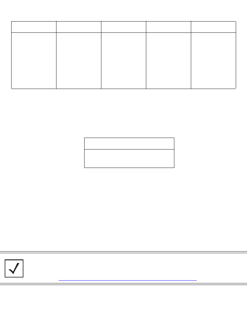
2.5.3 Single Radio 5.2 Ghz AP-7131 LEDs
The single 5.2 Ghz radio model AP-7131 has the following unique LED behavior:
2.5.4 Rear AP-7131 LED
The LED on the rear (bottom) of the AP-7131 is viewed using a single (customer installed) extended
light pipe, adjusted as required to suit above the ceiling installations. A LED displayed using the light
pipe has the following display and functionality:
3 Basic AP-7131 Configuration
For the basic setup described in this guide, the Java-based Web UI will be used to configure the
AP-7131. To access the AP-7131 via the GE1/POE port, the GE1/POE port default setting is DHCP
client. For this example, the AP-7131’s WAN interface will be used to connect to the access point.
The default WAN IP address is 10.1.1.1. For optimal viewing of the AP-7131 Web UI, the screen
resolution should be set to 1024 x 768 pixels or greater.
LED 1 LED 2 LED 3 LED 4 LED 5
Blinking Red
indicates booting.
Solid Red defines
a failure
condition. White
defines normal
operation
Green defines
normal GE1
operation.
Yellow defines a
collision
Green defines
normal GE2
operation.
Yellow defines a
collision
Amber defines
5.2 Ghz radio as
as configured
Emerald defines
2.4 Ghz radio as
configured
LED 1
White/Red defining power and boot
status
NOTE For advanced configuration options beyond the scope of this guide, refer
to the AP-7131 Product Reference Guide. The guide is available on the
Motorola Web site, at
http://support.symbol.com/support/product/manuals.do.
AP-7131 Access Point: Installation Guide
22
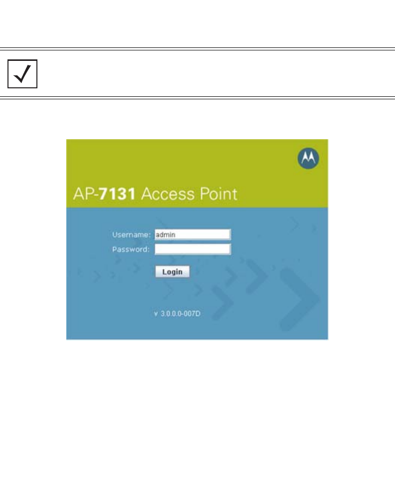
1. Start a browser and enter the following IP address in the address field:
http://10.1.1.1
The AP-7131 login screen displays.
2. Log in using admin as the default User ID and motorola as the default password. If the
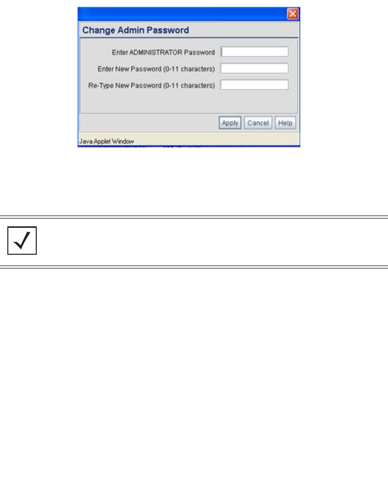
default login is successful, the Change Admin Password window displays.
3. Change the password.
NOTE For optimum compatibility, use Sun Microsystems’ JRE 1.5 or higher
(available from Sun’s Website), and be sure to disable Microsoft’s Java
Virtual Machine if installed.
Basic AP-7131 Configuration 23
Enter the current password and a new admin password in fields provided, and click Apply.
Once the admin password has been updated, a warning message displays stating the
AP-7131 could be operating illegally unless set to operate in the correct country. Proceed to
“Configuring “Basic” Device Settings” on page 24 to validate the country setting.
3.1 Resetting the AP-7131 Password
The AP-7131 Command Line Interface (CLI) enables users who forget their password to reset it to the
factory default (motorola). From there, a new password can be defined. To reset the AP-7131
password back to its default setting:
1. Connect one end of a null modem serial cable to the AP-7131’s serial connector. Attach the
other end of the null modem serial cable to the serial port of a PC running HyperTerminal or
a similar emulation program.
2. Set the HyperTerminal program to use 19200 baud, 8 data bits, 1 stop bit, no parity, no flow
control and auto-detect for terminal emulation.
3. Press <ESC> or <Enter> to access the AP-7131 CLI. A serial connection has now been
established and the user should be able to view the serial connection window.
4. Reset the AP-7131. An AP-7131 can be reset by removing and re-inserting the LAN
(GE1/POE) cable or removing and re-inserting the power cable.
NOTE Though the AP-7131 can have its basic settings defined using a number of
different screens, Motorola recommends using the AP-7131 Quick
Setup screen to define a minimum required configuration from one
location.
AP-7131 Access Point: Installation Guide
24
As the AP-7131 is re-booting, a “Press esc key to run boot firmware” message displays.
5. Quickly press <ESC>.
If the <ESC> key is pressed within three seconds a boot> prompt displays.
6. Reset the AP-7131 by typing the following at the boot prompt: reset system
When the AP-7131 re-boots again, the password will return to its default value of
“motorola.” You can now access the AP-7131.
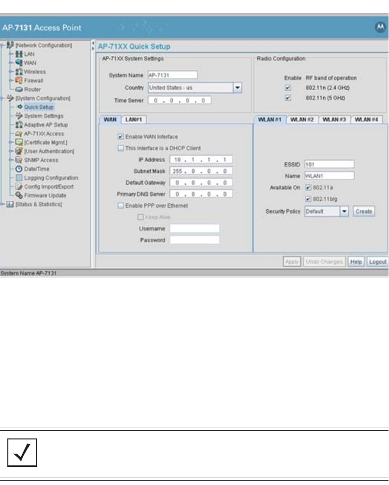
3.2 Configuring “Basic” Device Settings
Configure a set of minimum required device settings within the AP-7131 Quick Setup screen. The
values defined within the Quick Setup screen are also configurable in numerous other locations
within the AP-7131 menu tree. When you change the settings in the Quick Setup screen, the values
also change within the screen where these parameters also exist. Additionally, if the values are
updated in these other screens, the values initially set within the Quick Setup screen will be updated.
The following table illustrates the AP-7131’s default configuration.
To define a basic AP-7131 configuration:
CAUTION If the <ESC> key is not pressed within three seconds after the “Press
esc key to run boot firmware” message displays, the AP-7131 will
continue to boot.
WAN LAN 1 LAN 2
Access via WAN
port
Static IP: 10.1.1.1
Static Mask:
255.0.0.0
DHCP Client
Auto-Update
Enabled
Default Gateway
Ethernet Port
Enabled
Disabled HTTP, HTTPS, SSH,
SNMP, Telnet:
Enabled
!
Basic AP-7131 Configuration 25
1. Select System Configuration -> Quick Setup from the AP-7131 menu tree.
2. Enter a System Name for the AP-7131. The System Name is useful if multiple devices are
being administered.
3. Select the Country for the AP-7131’s country of operation from the drop-down menu.
The AP-7131 prompts the user for the correct country code on the first login. A warning
message also displays stating that an incorrect country setting may result in illegal radio
operation. Selecting the correct country is central to legally operating the AP-7131. Each
country has its own regulatory restrictions concerning electromagnetic emissions and the
maximum RF signal strength that can be transmitted. To ensure compliance with national
and local laws, be sure to set the Country accurately. CLI and MIB users cannot configure
their AP-7131 until a two character country code (for example, United States - us) is set.
NOTE The System Name and Country are also configurable within the System
Settings screen. Refer to the AP-7131 Product Reference Guide to
optionally set a system location and admin email address for the AP-7131
or to change other default settings.

AP-7131 Access Point: Installation Guide
26
4. Optionally enter the IP address of the server used to provide system time to the AP-7131
within the Time Server field.
Once the IP address is entered, the AP-7131’s Network Time Protocol (NTP) functionality is
engaged automatically. Refer to the AP-7131 Product Reference Guide for information on
defining alternate time servers and setting a synchronization interval for the AP-7131 to
adjust its displayed time.
5. Click the WAN tab to set a minimum set of parameters for using the WAN interface.
a. Select the Enable WAN Interface checkbox to enable a connection between the
AP-7131 and a larger network or outside world through the WAN port. Disable this
option to effectively isolate the AP-7131’s WAN connection. No connections to a larger
network or the Internet will be possible. MUs cannot communicate beyond the
configured subnets.
b. Select the This Interface is a DHCP Client checkbox to enable DHCP for the AP-7131
WAN connection. This is useful, if the target corporate network or Internet Service
Provider (ISP) uses DHCP. DHCP is a protocol that includes mechanisms for IP address
allocation and delivery of host-specific configuration parameters from a DHCP server to
a host. Some of these parameters are IP address, network mask, and gateway.
c. Specify an IP address for the AP-7131’s WAN connection. An IP address uses a series
of four numbers expressed in dot notation, for example, 190.188.12.1.
d. Specify a Subnet Mask for the AP-7131’s WAN connection. This number is available
from the ISP for a DSL or cable-modem connection, or from an administrator if the
AP-7131 connects to a larger network. A subnet mask uses a series of four numbers
expressed in dot notation. For example, 255.255.255.0 is a valid subnet mask.
e. Specify a Default Gateway address for the AP-7131’s WAN connection. The ISP or a
network administrator provides this address.
f. Specify the address of a Primary DNS Server. The ISP or a network administrator
provides this address.
6. Optionally, use the Enable PPP over Ethernet checkbox to enable Point-to-Point over
Ethernet (PPPoE) for a high-speed connection that supports this protocol. Most DSL
providers are currently using or deploying this protocol. PPPoE is a data-link protocol for
dialup connections. PPPoE will allow the AP-7131 to use a broadband modem (DSL, cable
modem, etc.) for access to high-speed data networks.
a. Select the Keep Alive checkbox to enable occasional communications over the WAN
port even when client communications to the WAN are idle. Some ISPs terminate
inactive connections, while others do not. In either case, enabling Keep-Alive maintains

Basic AP-7131 Configuration 27
the WAN connection, even when there is no traffic. If the ISP drops the connection after
the idle time, the AP-7131 automatically reestablishes the connection to the ISP.
b. Specify a Username entered when connecting to the ISP. When the Internet session
begins, the ISP authenticates the username.
c. Specify a Password entered when connecting to the ISP. When the Internet session
starts, the ISP authenticates the password.
7. Click the LAN tab to set a minimum set of parameters to use the AP-7131 LAN interface.
a. Select the Enable LAN Interface checkbox to forward data traffic over the AP-7131
LAN connection. The LAN connection is enabled by default.
b. Use the This Interface drop-down menu to specify how network address information is
defined over the AP-7131’s LAN connection. Select DHCP Client if the larger corporate
network uses DHCP. DHCP is a protocol that includes mechanisms for IP address
allocation and delivery of host-specific configuration parameters from a DHCP server to
a host. Some of these parameters are IP address, network mask, and gateway. Select
DHCP Server to use the AP-7131 as a DHCP server over the LAN connection.
c. Enter the network-assigned IP Address of the AP-7131.
d. The Subnet Mask defines the size of the subnet. The first two sets of numbers specify
the network domain, the next set specifies the subset of hosts within a larger network.
These values help divide a network into subnetworks and simplify routing and data
transmission.
e. Enter a Default Gateway to define the IP address of a router the AP-7131 uses on the
Ethernet as its default gateway.
f. Enter the Primary DNS Server IP address.
g. If using DHCP Server, use the Address Assignment Range parameter to specify a
range of IP address reserved for mapping clients to IP addresses. If a manually (static)
mapped IP address is within the IP address range specified, that IP address could still be
assigned to another client. To avoid this, ensure all statically mapped IP addresses are
outside of the IP address range assigned to the DHCP server.
8. Enable the radio(s) using the Radio Enable checkbox(es). If using a single radio model,
enable the radio, then select either 802.11a (5 GHz) or 802.11b/g (2.4 GHz) from the RF Band
NOTE For additional AP-7131 port configuration options, as well as radio, WLAN
and Quality of Service (QoS) options, refer to the
AP-7131 Product Reference Guide.
AP-7131 Access Point: Installation Guide
28
of Operation field. Only one RF band option at a time is permissible in a single-radio model.
If using a dual-radio AP-7131, the user can enable both RF bands.
9. Select the WLAN #1 tab (WLANs 1 - 4 are available within the Quick Setup screen) to define
its ESSID security scheme for basic operation.
a. Enter the Extended Services Set Identification (ESSID) and name associated with the
WLAN.
b. Use the Available On checkboxes to define whether the target WLAN is operating over
the 802.11a or 802.11b/g radio. Ensure the radio selected has been enabled (see step 8).
10. Once the WLAN’s radio designations have been made, the radio must be configured in
respect to intended 2.4 or 5 GHz radio traffic and the antennas used. Refer to Network
Configuration -> Wireless -> Radio Configuration -> Radio1 (or Radio2), and
configure the Radio Settings field (at a minimum). If you know the radio’s Properties,
Performance and Beacon Settings, those fields can also be defined at this time.
Define the Channel Settings, Power Level and 802.11 mode in respect to the 2.4 or 5 GHz
802.11b/g/n or 802.11a/n radio traffic and anticipated gain of the antennas.
NOTE A maximum of 16 WLANs are configurable within the AP-7131 Wireless
Configuration screen. The limitation of 16 WLANs exists regardless of the
number of radios supported.
CAUTION Only a qualified wireless network administrator should set the access
point radio configuration. Refer to the AP-7131 Product Reference
Guide for an understanding of the configurable values involved and
their implications. To access the guide, go to
http://support.symbol.com/support/product/manuals.do.
NOTE Even an AP-7131 configured with minimal values must protect its data
against theft and corruption. A security policy should be configured for
WLAN1 as part of the basic configuration outlined in this guide. A security
policy can be configured for the WLAN from within the Quick Setup
screen. Policies can be defined over time and saved to be used as needed
as the AP-7131’s security requirements change. Motorola recommends
you familiarize yourself with the security options available on the AP-7131
before defining a security policy.
!
Basic AP-7131 Configuration 29
11. Click Apply to save any changes to the AP-7131 Quick Setup screen. Navigating away from
the screen without clicking Apply results in all changes to the screens being lost, unless you
use the Un-applied Changes pop-up window to overwrite the current settings.
12. Click Undo Changes (if necessary) to undo any changes made. Undo Changes reverts the
settings displayed on the AP-7131 Quick Setup screen to the last saved configuration.
3.2.1 Configuring Basic AP-7131 Security
For testing basic connectivity, there is no reason to configure a server supported authentication
scheme. WEP 128 is described in this guide as a basic security scheme sufficient to protect the
AP-7131’s initial transmissions. For details on configuring more sophisticated authentication and
encryption options available to the AP-7131, refer to the AP-7131 Product Reference Guide. The guide
is available on the Motorola Web site, at http://support.symbol.com/support/product/manuals.do.
To configure WEP 128:
1. From the AP-7131 Quick Setup screen, click the Create button to the right of the Security
Policy item.
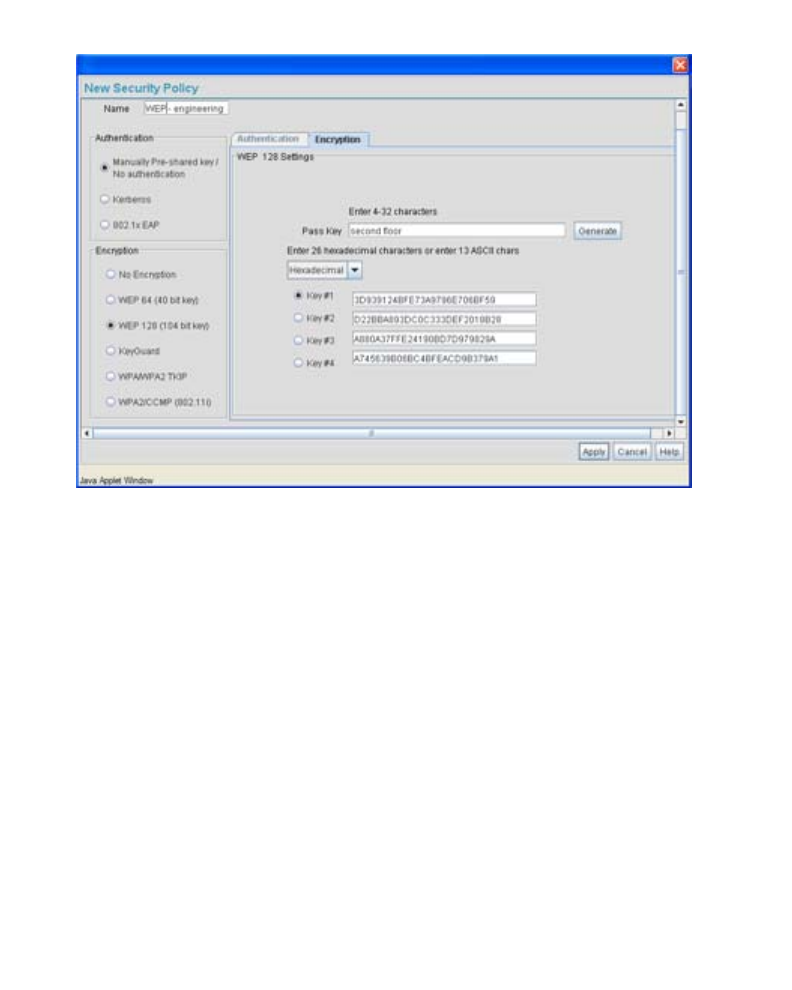
The New Security Policy screen displays with the Manually Pre-shared key/No
authentication and No Encryption options selected. Naming and saving such a policy (as is)
would provide no security and might only make sense in a guest network wherein no
sensitive data is either transmitted or received. Consequently, at a minimum, a basic
security scheme (in this case WEP 128) is recommended.
2. Ensure the Name of the security policy entered suits the intended configuration or function
of the policy.
Multiple WLANs can share the same security policy, so be careful not to name security
policies after specific WLANs or risk defining a WLAN to single policy. Motorola
recommends naming the policy after the attributes of the authentication or encryption
type selected.
NOTE For information on configuring the other (more sophisticated) encryption
and authentication options available to the AP-7131, refer to the
AP-7131 Product Reference Guide. The guide is available on the Motorola
Web site, at http://support.symbol.com/support/product/manuals.do.
AP-7131 Access Point: Installation Guide
30
3. Select the WEP 128 (104 bit key) checkbox.The WEP 128 Setting field displays within the
New Security Policy screen.
4. Configure the WEP 128 Setting field as required to define the Pass Key used to generate
the WEP keys.
5. Click the Apply button to save the security policy and return to the AP-7131 Quick Setup
screen.
Pass Key Specify a 4 to 32 character pass key and click the Generate button.
The AP-7131, other proprietary routers and Motorola MUs use the
same algorithm to convert an ASCII string to the same hexadecimal
number. Non-Motorola clients and devices need to enter WEP keys
manually as hexadecimal numbers. The AP-7131 and its target
client(s) must use the same pass key to interoperate.
Keys #1-4 Use the Key #1-4 fields to specify key numbers. The key can be
either a hexidecimal or ASCII depending on which option is
selected from the drop-down menu. For WEP 64 (40-bit key), the
keys are 10 hexadecimal characters in length or 5 ASCII characters.
For WEP 128 (104-bit key), the keys are 26 hexadecimal characters
in length or 13 ASCII characters. Select one of these keys for
activation by clicking its radio button. The AP-7131 and its target
client(s) must use the same key to interoperate.
Basic AP-7131 Configuration 31
At this point, you can either restrict specific MU access to the AP-7131 (using the AP-7131
ACL) or test the AP-7131 for MU interoperability.
3.2.2 Excluding MUs from AP-7131 Association
Optionally, use the AP-7131 Access Control List ACL to specify which MUs can or cannot gain access
to an AP-7131 managed WLAN. By default, all mobile units can gain access. For specific information
on configuring (restricting) MU access, refer to the AP-7131 Product Reference Guide. The guide is
available on the Motorola Web site, at http://support.symbol.com/support/product/manuals.do.
3.2.3 Testing Mobile Unit Connectivity
Verify the AP-7131’s link with an MU by sending Wireless Network Management Protocol (WNMP)
ping packets to the associated MU. Use the Echo Test screen to specify a target MU and configure
the parameters of the ping test. The WNMP ping test only works with Motorola MUs. Only use a
Motorola MU to test AP-7131 connectivity using WNMP.
To ping a specific MU to assess its connection with an AP-7131:
1. Select Status and Statistics - > MU Stats from the AP-7131 menu tree.
2. Select the Echo Test button from within the MU Stats Summary screen.
3. Define the following ping test parameters:
4. Click the Ping button to begin transmitting ping packets to the MU address specified.
NOTE Before testing for connectivity, the target MU needs to be set to the same
ESSID as the AP-7131. Since WEP 128 has been configured for the
AP-7131, the MU also needs to be configured for WEP 128 and use the
same WEP keys. Ensure the MU is associated with the AP-7131 before
testing for connectivity.
Station Address The station address is the IP address of the target MU. Refer to the
MU Stats Summary screen for associated MU IP address
information.
Number of ping Specify the number of ping packets to transmit to the target MU.
The default is 100.
Packet Length Specify the length of each data packet transmitted to the target
MU during the ping test. The default is 100 bytes.

AP-7131 Access Point: Installation Guide
32
Refer to the Number of Responses value to assess the number of responses from the
target MU versus the number of pings transmitted by the AP-7131. Use the ratio of packets
sent versus packets received to assess the link quality between MU and the AP-7131.
Click the Ok button to exit the Echo Test screen and return to the MU Stats Summary screen.
With basic AP-7131 and associated MU connectivity verified, the AP-7131 is now ready to
operate as defined within this guide or have its more advanced features configured.
3.3 Where to Go From Here?
Once basic connectivity has been verified, the AP-7131 can be fully configured to meet the needs of
the network and the users it supports. The sections referenced below are located within the
AP-7131 Product Reference Guide. The guide is available on the Motorola Web site, at
http://support.symbol.com/support/product/manuals.do.
• Refer to Chapter 4 to define System Settings (beyond the scope of the Quick Setup screen),
configure AP-7131 device access, set SNMP values, log system events, set the AP-7131
system time and import device firmware and configuration files.
• See Chapter 5 for information on configuring the AP-7131 LAN and WAN ports, define up to
16 individual WLANs and their QoS policies and configure AP-7131 router settings.
• Refer to Chapter 6 for detailed information on configuring specific encryption (WEP,
KeyGuard, WPA/TKIP and WPA2/CCMP) and authentication (Kerberos and 802.1x EAP)
security schemes.
• See Chapter 7 for information on accessing statistics helpful in monitoring the connection
between the AP-7131 and its connected devices.
• Refer to Chapter 8 for information on using the AP-7131 Command Line Interface (CLI), as
accessed through the serial port or Telnet.
• See Appendix A for device specifications.
Regulatory Compliance 33
4 Regulatory Compliance
This device is approved under the Symbol Technologies brand; Symbol Technologies, Inc., is the Enterprise Mobility business
of Motorola, Inc (“Motorola”).
All Motorola devices are designed to be compliant with rules and regulations in locations they are sold and will be labeled
as required. Any changes or modifications to Motorola equipment, not expressly approved by Motorola, could void the user's
authority to operate the equipment.
Motorola's devices are professionally installed, the Radio Frequency Output Power will not exceed the maximum allowable
limit for the country of operation.
Antennas: Use only the supplied or an approved replacement antenna. Unauthorized antennas, modifications, or
attachments could cause damage and may violate regulations.
This guide is available in local languages, translations can be downloaded from the following website:
http://support.symbol.com/support/product/manuals.do.
Country Approvals
Regulatory markings are applied to the device signifying the radio (s) are approved for use in the following countries: United
States, Canada, Australia, Japan and Europe.
Please refer to the Declaration of Conformity (DoC) for details of other country markings. This is available at
http://www2.symbol.com/doc/.
Note 1: For 2.4GHz Products: Europe includes, Austria, Belgium, Bulgaria, Czech Republic, Cyprus, Denmark, Estonia,
Finland, France, Germany, Greece, Hungary, Iceland, Ireland, Italy, Latvia, Liechtenstein, Lithuania, Luxembourg, Malta,
Netherlands, Norway, Poland, Portugal, Romania, Slovak Republic, Slovenia, Spain, Sweden, Switzerland and the
United Kingdom.
Operation of the device without regulatory approval is illegal.
Health and Safety Recommendations
Warnings for the use of Wireless Devices
Please observe all warning notices with regard to the usage of wireless devices
Potentially Hazardous Atmospheres
You are reminded of the need to observe restrictions on the use of radio devices in fuel depots, chemical plants etc. and
areas where the air contains chemicals or particles (such as grain, dust, or metal powders).

AP-7131 Access Point: Installation Guide
34
Safety in Hospitals
Wireless devices transmit radio frequency energy and may affect medical electrical equipment. When installed adjacent to
other equipment, it is advised to verify that the adjacent equipment is not adversely affected.
RF Exposure Guidelines
Safety Information
The device complies with Internationally recognized standards covering human exposure to electromagnetic fields from
radio devices.
Reducing RF Exposure—Use Properly
Only operate the device in accordance with the instructions supplied.
Remote and Standalone Antenna Configurations
To comply with FCC RF exposure requirements, antennas that are mounted externally at remote locations or operating near
users at stand-alone desktop of similar configurations must operate with a minimum separation distance of 20 cm from all
persons.
Power Supply
Use only a Motorola approved power supply output rated at 48Vdc and minimum 0.75A. The power supply shall be Listed
to UL/CSA 60950-1; and certified to IEC60950-1 and EN60950-1 with SELV outputs.
Use only a Motorola approved power supply. Use of alternative power supply will invalidate any approval given to this
device and may be dangerous.
Wireless Devices - Countries
Country Selection
Select only the country in which you are using the device. Any other selection will make the operation of this device illegal.
Operation in the US
The use on UNII (Unlicensed National Information Infrastructure) Band 1 5150-5250 MHz is restricted to indoor use only, any
other use will make the operation of this device illegal.
The available channels for 802.11 b/g operation in the US are Channels 1 to 11. The range of channels is limited by firmware.

Regulatory Compliance 35
Radio Frequency Interference Requirements—FCC
This equipment has been tested and found to comply with the limits for a Class B digital device,
pursuant to Part 15 of the FCC rules. These limits are designed to provide reasonable protection
against harmful interference in a residential installation. This equipment generates, uses and can
radiate radio frequency energy and, if not installed and used in accordance with the instructions, may
cause harmful interference to radio communications. However there is no guarantee that interference will not occur in a
particular installation. If this equipment does cause harmful interference to radio or television reception, which can be
determined by turning the equipment off and on, the user is encouraged to try to correct the interference by one or more of
the following measures:
• Reorient or relocate the receiving antenna
• Increase the separation between the equipment and receiver
• Connect the equipment into an outlet on a circuit different from that to which the receiver is connected
• Consult the dealer or an experienced radio/TV technician for help.
Radio Transmitters (Part 15)
This device complies with Part 15 of the FCC Rules. Operation is subject to the following two conditions: (1) this device may
not cause harmful interference, and (2) this device must accept any interference received, including interference that may
cause undesired operation.
Radio Frequency Interference Requirements – Canada
This Class B digital apparatus complies with Canadian ICES-003.
Cet appareil numérique de la classe B est conforme à la norme NMB-003 du Canada.
Devices using the 5.470 – 5.725 GHz band shall not be capable of transmitting in the band 5.60-5.65 GHz in Canada, make
sure that Canada is the country selected during setup to ensure compliance.
Radio Transmitters
This device complies with RSS 210 of Industry & Science Canada. Operation is subject to the following two conditions: (1)
this device may not cause harmful interference and (2) this device must accept any interference received, including
interference that may cause undesired operation.
To reduce potential radio interference to other users, the antenna type and its gain should be so chosen that the equivalent
isotropically radiated power (EIRP) is not more than that permitted for successful communication.
This device has been designed to operate with the antennas listed in section 3.3.1 of this installation guide, and having a
maximum gain of 13.9 dBi (2.4 GHz) and 13 dBi (5 GHz). Antennas not included in this list or having a gain greater than
13.9 dBi (2.4 GHz) and 13 dBi (5 GHz) are strictly prohibited for use with this device. The required antenna impedance is
50 ohms.
Label Marking: The Term "IC:" before the radio certification signifies that Industry Canada technical specifications were met.

AP-7131 Access Point: Installation Guide
36
CE Marking and European Economic Area (EEA)
The use of 2.4GHz RLAN’s, for use through the EEA, have the following restrictions:
• Maximum radiated transmit power of 100 mW EIRP in the frequency range 2.400 -2.4835 GHz.
• France outside usage, the equipment is restricted to 2.400-2.45 GHz frequency range.
• Italy requires a user license for outside usage.
Statement of Compliance
Motorola hereby, declares that this device is in compliance with the essential requirements and other relevant provisions
of Directive 1999/5/EC. A Declaration of Conformity may be obtained from
http://www2.symbol.com/doc/.
NOTICE!
According to: Administrative Regulations on Low Power Radio Waves Radiated Devices
Article 12
Without permission granted by the DGT, any company, enterprise, or user is not allowed to change frequency, enhance
transmitting power or alter original characteristic as well as performance to a approved low power radio-frequency devices.
Article 14
The low power radio-frequency devices shall not influence aircraft security and interfere legal communications; If found,
the user shall cease operating immediately until no interference is achieved. The said legal communications means radio
communications is operated in compliance with the Telecommunications Act. The low power radio-frequency devices must
be susceptible with the interference from legal communications or ISM radio wave radiated devices.
FCC Caution: Any changes or modifications not expressly approved by the party responsible for compliance could void
the user’s authority to operate this equipment.
Country Code Statement
For product available in the USA/Canada market, only channel 1~11 can be operated. Selection of other channels is not
possible.
This device and its antenna(s) must not be co-located or operation in conjunction with any other antenna or transmitter.
For IEEE 802.11a 5GHz Statement
This device is going to be operated in 5.15~5.25GHz frequency range, it is restricted in indoor environment only.
For MPE Statement – Mobile device
IMPORTANT NOTE:
FCC Radiation Exposure Statement:
This equipment complies with FCC radiation exposure limits set forth for an uncontrolled environment. This equipment
should be installed and operated with minimum distance 20cm between the radiator & your body.

Regulatory Compliance 37
IMPORTANT NOTE: This module is intended for OEM integrator only and limited to host with brand: Motorola and
model: AP-7131-MB82. The OEM integrator is still responsible for the FCC compliance requirement of the end
product, which integrates this module. 20cm minimum distance has to be able to be maintained between the
antenna and the users for the host this module is integrated into. Under such configuration, the FCC radiation
exposure limits set forth for a population/uncontrolled environment can be satisfied. Any changes or modifications not
expressly approved by the manufacturer could void the user's authority to operate this equipment. USERS MANUAL
OF THE END PRODUCT: In the users manual of the end product, the end user has to be informed to keep at least
20cm separation with the antenna while this end product is installed and operated. The end user has to be informed
that the FCC radio-frequency exposure guidelines for an uncontrolled environment can be satisfied. The end user has
to also be informed that any changes or modifications not expressly approved by the manufacturer could void the
user's authority to operate this equipment. LABEL OF THE END PRODUCT: The final end product must be labeled
in a visible area with the following " Contains TX FCC ID: UZ7AP7131 ". The FCC part 15.19 statement below has to
also be available on the label: This device complies with Part 15 of FCC rules. Operation is subject to the following
two conditions: (1) this device may not cause harmful interference and (2) this device must accept any interference
received, including interference that may cause undesired operation.
The device could automatically discontinue transmission in case of absence of information to transmit, or
operational failure. Note that this is not intended to prohibit transmission of control or signaling information or the
use of repetitive codes where required by the technology.
The device for the band 5150-5250 MHz is only for indoor usage to reduce potential for harmful interference to co-
channel mobile satellite systems.
The maximum antenna gain permitted (for devices in the bands 5250-5350 MHz and 5470-5725 MHz) to comply
with the e.i.r.p. limit.
The maximum antenna gain permitted (for devices in the band 5725-5825 MHz) to comply with the e.i.r.p. limits
specified for point-to-point and non point-to-point operation as appropriate, as stated in section A9.2(3).
High-power radars are allocated as primary users (meaning they have priority) of the bands 5250-5350 MHz and
5650-5850 MHz and these radars could cause interference and/or damage to LE-LAN devices.
IMPORTANT NOTE: This module is intended for OEM integrator only and limited to host with brand: Motorola and
model: UZ7AP7131. The OEM integrator is still responsible for the IC compliance requirement of the end product, which
integrates this module. 20cm minimum distance has to be able to be maintained between the antenna and the users for
the host this module is integrated into. Under such configuration, the IC RSS-102 radiation exposure limits set forth for a
population/uncontrolled environment can be satisfied. Any changes or modifications not expressly approved by the
manufacturer could void the user's authority to operate this equipment. USERS MANUAL OF THE END PRODUCT: In
the users manual of the end product, the end user has to be informed to keep at least 20cm separation with the antenna
while this end product is installed and operated. The end user has to be informed that the IC radio-frequency exposure
guidelines for an uncontrolled environment can be satisfied. The end user has to also be informed that any changes or
modifications not expressly approved by the manufacturer could void the user's authority to operate this equipment. IC
statement is required to be available in the users manual: This Class B digital apparatus complies with Canadian
ICES-003. Operation is subject to the following two conditions: (1) this device may not cause harmful interference and (2)
this device must accept any interference received, including interference that may cause undesired operation. LABEL
OF THE END PRODUCT: The final end product must be labeled in a visible area with the following " Contains TX IC:
109AN–AP7131 ".
AP-7131 Access Point: Installation Guide
38
5Waste Electrical and Electronic Equipment (WEEE)
English: For EU Customers: All products at the end of their life must be returned to Symbol for
recycling. For information on how to return product, please go to:
http://www.symbol.com/environmental_compliance.
Dansk: Til kunder i EU: Alle produkter skal returneres til Symbol til recirkulering, når de er
udtjent. Læs oplysningerne om returnering af produkter på: http://www.symbol.com/
environmental_compliance.
Deutsch: Für Kunden innerhalb der EU: Alle Produkte müssen am Ende ihrer Lebensdauer zum
Recycling an Symbol zurückgesandt werden. Informationen zur Rücksendung von Produkten
finden Sie unter http://www.symbol.com/environmental_compliance.
Eesti: EL klientidele: kõik tooted tuleb nende eluea lõppedes tagastada taaskasutamise
eesmärgil Symbol'ile. Lisainformatsiooni saamiseks toote tagastamise kohta külastage palun
aadressi: http://www.symbol.com/environmental_compliance.
Español: Para clientes en la Unión Europea: todos los productos deberán entregarse a Symbol
al final de su ciclo de vida para que sean reciclados. Si desea más información sobre cómo
devolver un producto, visite: http://www.symbol.com/environmental_compliance.
Français : Clients de l'Union Européenne : Tous les produits en fin de cycle de vie doivent être
retournés à Symbol pour recyclage. Pour de plus amples informations sur le retour de produits,
consultez : http://www.symbol.com/environmental_compliance.
Italiano: per i clienti dell'UE: tutti i prodotti che sono giunti al termine del rispettivo ciclo di
vita devono essere restituiti a Symbol al fine di consentirne il riciclaggio. Per informazioni sulle
modalità di restituzione, visitare il seguente sito Web: http://www.symbol.com/
environmental_compliance.
Magyar: Az EU-ban vásárlóknak: Minden tönkrement terméket a Symbol vállalathoz kell
eljuttatni újrahasznosítás céljából. A termék visszajuttatásának módjával kapcsolatos
tudnivalókért látogasson el a http://www.symbol.com/environmental_compliance weboldalra
Waste Electrical and Electronic
Equipment (WEEE)
39
Nederlands: Voor klanten in de EU: alle producten dienen aan het einde van hun levensduur
naar Symbol te worden teruggezonden voor recycling. Raadpleeg http://www.symbol.com/
environmental_compliance voor meer informatie over het terugzenden van producten.
Português: Para clientes da UE: todos os produtos no fim de vida devem ser devolvidos à
Symbol para reciclagem. Para obter informações sobre como devolver o produto, visite: http:/
/www.symbol.com/environmental_compliance.
Slovenski: Za kupce v EU: vsi izdelki se morajo po poteku življenjske dobe vrniti podjetju
Symbol za reciklažo. Za informacije o vraèilu izdelka obišèite: http://www.symbol.com/
environmental_compliance.
Suomi: Asiakkaat Euroopan unionin alueella: Kaikki tuotteet on palautettava kierrätettäväksi
Symbol-yhtiöön, kun tuotetta ei enää käytetä. Lisätietoja tuotteen palauttamisesta on
osoitteessa http://www.symbol.com/environmental_compliance.

AP-7131 Access Point: Installation Guide
40
6 Motorola’s Enterprise Mobility Support Center
If you have a problem with your equipment, contact Enterprise Mobility support for your region.
Contact information is available at: http://support.symbol.com/support/.
When contacting Enterprise Mobility support, please provide the following information:
• Serial number of the unit
• Model number or product name
• Software type and version number
Motorola responds to calls by email, telephone or fax within the time limits set forth in support
agreements. If you purchased your Enterprise Mobility business product from a Motorola business
partner, contact that business partner for support.
Customer Support Web Sites
Motorola's Support Central Web site, located at http://support.symbol.com/support/ provides
information and online assistance including developer tools, software downloads, product manuals
and online repair requests.
Manuals
http://support.symbol.com/support/product/manuals.do
General Information
Obtain additional information by contacting Motorola at:
Telephone (North America): 1-800-722-6234
Telephone (International): +1-631-738-5200
Website: http://www.motorola.com

MOTOROLA INC
1303 E. ALGONQUIN ROAD
SCHAUMBURG, IL 60196
http://www.motorola.com
72-109210-01 Revision A
April 2008