Zebra Technologies AP7131N 11n Access Point User Manual AP7131 InstallationGuide MN000037A01
Zebra Technologies Corporation 11n Access Point AP7131 InstallationGuide MN000037A01
Contents
- 1. UZ7AP7131N revised
- 2. UserMan UZ7AP7131N revised
- 3. Antenna_Guide_1.9_Rev_B
- 4. Users Manual Rev 2
Users Manual Rev 2
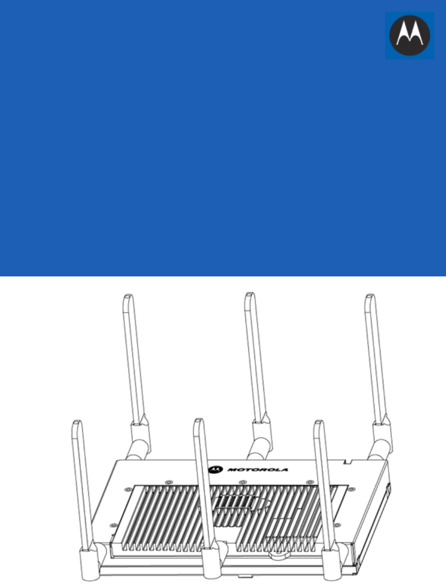
AP7131 Access Point
INSTALLATION GUIDE

2AP-7131 Access Point
MOTOROLA SOLUTIONS and the Stylized M Logo are registered in the US Patent & Trademark Office. © Motorola Solutions,
Inc. 2013. All rights reserved.

Installation Guide 3
1.0 Introduction . . . . . . . . . . . . . . . . . . . . . . . . . . . . . . . . . . . . . . . . . . . . . . . . . . . . . . 5
1.1 Document Conventions . . . . . . . . . . . . . . . . . . . . . . . . . . . . . . . . . . . . . . . . . . . . 5
1.2 Warnings . . . . . . . . . . . . . . . . . . . . . . . . . . . . . . . . . . . . . . . . . . . . . . . . . . . . . . . 6
1.3 Site Preparation . . . . . . . . . . . . . . . . . . . . . . . . . . . . . . . . . . . . . . . . . . . . . . . . . . 6
2.0 Hardware Installation . . . . . . . . . . . . . . . . . . . . . . . . . . . . . . . . . . . . . . . . . . . . . . 7
2.1 Precautions . . . . . . . . . . . . . . . . . . . . . . . . . . . . . . . . . . . . . . . . . . . . . . . . . . . . . . 7
2.2 Package Contents . . . . . . . . . . . . . . . . . . . . . . . . . . . . . . . . . . . . . . . . . . . . . . . . . 7
2.3 Access Point Placement . . . . . . . . . . . . . . . . . . . . . . . . . . . . . . . . . . . . . . . . . . . . 8
2.3.1 Antenna Options. . . . . . . . . . . . . . . . . . . . . . . . . . . . . . . . . . . . . . . . . . . . . . 9
2.3.2 Power Injector System . . . . . . . . . . . . . . . . . . . . . . . . . . . . . . . . . . . . . . . . 11
2.4 Mounting the Access Point. . . . . . . . . . . . . . . . . . . . . . . . . . . . . . . . . . . . . . . . . 13
2.4.1 Wall Mounting . . . . . . . . . . . . . . . . . . . . . . . . . . . . . . . . . . . . . . . . . . . . . . 13
2.4.2 Suspended Ceiling T-Bar Installation. . . . . . . . . . . . . . . . . . . . . . . . . . . . . 17
2.4.3 Above the Ceiling (Plenum) Installation. . . . . . . . . . . . . . . . . . . . . . . . . . . 19
2.5 LED Indicators . . . . . . . . . . . . . . . . . . . . . . . . . . . . . . . . . . . . . . . . . . . . . . . . . . . 22
2.5.1 Three Radio AP7131 LEDs . . . . . . . . . . . . . . . . . . . . . . . . . . . . . . . . . . . . . 23
2.5.2 Dual Radio (2.4/5 GHz) LEDs . . . . . . . . . . . . . . . . . . . . . . . . . . . . . . . . . . . 23
2.5.3 Single Radio 2.4 GHz LEDs. . . . . . . . . . . . . . . . . . . . . . . . . . . . . . . . . . . . . 24
2.5.4 Single Radio 5 GHz LEDs . . . . . . . . . . . . . . . . . . . . . . . . . . . . . . . . . . . . . . 24
2.5.5 Rear AP7131 LED . . . . . . . . . . . . . . . . . . . . . . . . . . . . . . . . . . . . . . . . . . . . 25
3.0 Basic Access Point Configuration . . . . . . . . . . . . . . . . . . . . . . . . . . . . . . . . . . 26
4.0 Specifications. . . . . . . . . . . . . . . . . . . . . . . . . . . . . . . . . . . . . . . . . . . . . . . . . . . . 34
4.1 AP7131 Physical Characteristics . . . . . . . . . . . . . . . . . . . . . . . . . . . . . . . . . . . . 34
4.2 AP7131N Physical Characteristics . . . . . . . . . . . . . . . . . . . . . . . . . . . . . . . . . . . 34
4.3 Electrical Characteristics . . . . . . . . . . . . . . . . . . . . . . . . . . . . . . . . . . . . . . . . . . 35
4.4 AP7131 Radio Characteristics . . . . . . . . . . . . . . . . . . . . . . . . . . . . . . . . . . . . . . 35
4.5 AP7131N Radio Characteristics . . . . . . . . . . . . . . . . . . . . . . . . . . . . . . . . . . . . . 36
5.0 Regulatory Information . . . . . . . . . . . . . . . . . . . . . . . . . . . . . . . . . . . . . . . . . . . . 37
5.1 Regulatory Overview. . . . . . . . . . . . . . . . . . . . . . . . . . . . . . . . . . . . . . . . . . . . . . 37

4AP-7131 Access Point
5.2Wireless Country Approvals . . . . . . . . . . . . . . . . . . . . . . . . . . . . . . . . . . . . . . . . 37
5.3 Health and Safety Recommendations . . . . . . . . . . . . . . . . . . . . . . . . . . . . . . . . 37
5.3.1 Warnings for the use of Wireless Devices . . . . . . . . . . . . . . . . . . . . . . . . 37
5.3.2 Potentially Hazardous Atmospheres - Fixed Installations . . . . . . . . . . . . . 38
5.3.3 Safety in Hospitals . . . . . . . . . . . . . . . . . . . . . . . . . . . . . . . . . . . . . . . . . . . 38
5.4 RF Exposure Guidelines . . . . . . . . . . . . . . . . . . . . . . . . . . . . . . . . . . . . . . . . . . . 38
5.4.1 Safety Information . . . . . . . . . . . . . . . . . . . . . . . . . . . . . . . . . . . . . . . . . . . 38
5.5 Power Supply . . . . . . . . . . . . . . . . . . . . . . . . . . . . . . . . . . . . . . . . . . . . . . . . . . . 39
5.6 Wireless Devices - Countries . . . . . . . . . . . . . . . . . . . . . . . . . . . . . . . . . . . . . . . 39
5.7 Radio Frequency Interference Requirements - FCC . . . . . . . . . . . . . . . . . . . . . . 39
5.8 Radio Frequency Interference Requirements - Canada . . . . . . . . . . . . . . . . . . . 40
5.8.1 Radio Transmitters . . . . . . . . . . . . . . . . . . . . . . . . . . . . . . . . . . . . . . . . . . . 40
5.9 CE Marking and European Economic Area (EEA) . . . . . . . . . . . . . . . . . . . . . . . . 41
5.9.1 Statement of Compliance. . . . . . . . . . . . . . . . . . . . . . . . . . . . . . . . . . . . . . 41
5.9.2 Japan (VCCI) - Voluntary Control Council for Interference . . . . . . . . . . . . 41
5.9.3 Korea Warning Statement for Class B. . . . . . . . . . . . . . . . . . . . . . . . . . . . 42
5.9.4 Other Countries . . . . . . . . . . . . . . . . . . . . . . . . . . . . . . . . . . . . . . . . . . . . . 42
5.10 Waste Electrical and Electronic Equipment (WEEE). . . . . . . . . . . . . . . . . . . . . 45
5.11 Turkish WEEE Statement of Compliance . . . . . . . . . . . . . . . . . . . . . . . . . . . . . 46
6.0 Motorola Solutions Support Center . . . . . . . . . . . . . . . . . . . . . . . . . . . . . . . . . 47
7.0 AP7131 Series RoHS Compliance . . . . . . . . . . . . . . . . . . . . . . . . . . . . . . . . . . . 48
Installation Guide 5
1 Introduction
As a standalone Access Point, an AP7131 series Access Point provides small and medium-sized businesses with a
consolidated wired and wireless networking infrastructure, all in a single device. The integrated router, gateway,
firewall, DHCP and Power-over-Ethernet (PoE) simplify and reduce the costs associated with networking by
eliminating the need to purchase and manage multiple pieces of equipment.
The Access Point is also designed to meet the needs of large, distributed enterprises by converging the
functionality of a thick Access Point and thin access port into a single device. This mode enables the deployment
of a fully featured intelligent Access Point that can be centrally configured and managed via a Motorola Solutions
wireless switch in either corporate headquarters or a network operations center (NOC). In the event the connection
between the Access Point and the wireless switch is lost, a Remote Site Survivability (RSS) feature ensures the
delivery of uninterrupted wireless services at the local or remote site. All traffic between the adaptive Access
Points and the wireless switch is secured though an IPSec tunnel. Additionally, compatibility with Motorola
Solutions’ RF Management Suite (RFMS) allows you to centrally plan, deploy, monitor and secure large
deployments.
An AP7131N model Access Point supports the same feature set as existing AP7131 model Access Points, however
AP7131N Access Points support a three radio model (with the third radio dedicated exclusively to WIPS support).
1.1 Document Conventions
The following graphical alerts are used in this document to indicate notable situations:
NOTE Both the AP7131 and AP7131N model Access Points share the same Web
User Interface (UI) and installation methods. Therefore, the UI and
installation descriptions within this guide apply to both models.
NOTE Tips, hints, or special requirements that you should take note of.
CAUTION Care is required. Disregarding a caution can result in data loss or
equipment malfunction.
WARNING! Indicates a condition or procedure that could result in personal injury or
equipment damage.
!

6AP-7131 Access Point
1.2 Warnings
• Read all installation instructions and site survey reports, and verify correct equipment installation before
connecting the Access Point.
• Remove jewelry and watches before installing this equipment.
• Verify the unit is grounded before connecting it to the power source.
• Verify any device connected to this unit is properly wired and grounded.
• Connect all power cords to a properly wired and grounded electrical circuit.
• Verify that the electrical circuits have appropriate overload protection.
• Attach only approved power cords to the device.
• Verify that the power connector and socket are accessible at all times during the operation of the
equipment.
• Verify there is adequate ventilation around the device, and that ambient temperatures meet equipment
operation specifications.
1.3 Site Preparation
• Consult your site survey and network analysis reports to determine specific equipment placement, power
drops, and so on.
• Assign installation responsibility to the appropriate personnel.
• Identify and document where all installed components are located.
• Ensure adequate, dust-free ventilation to all installed equipment.
• Prepare Ethernet port connections.
• Verify cabling is within the maximum 100 meter allowable length.
.

Installation Guide 7
2 Hardware Installation
An AP7131 or AP7131N Access Point installation includes mounting the Access Point, connecting the Access Point
to the network, connecting antennae and applying power. Installation procedures vary for different environments.
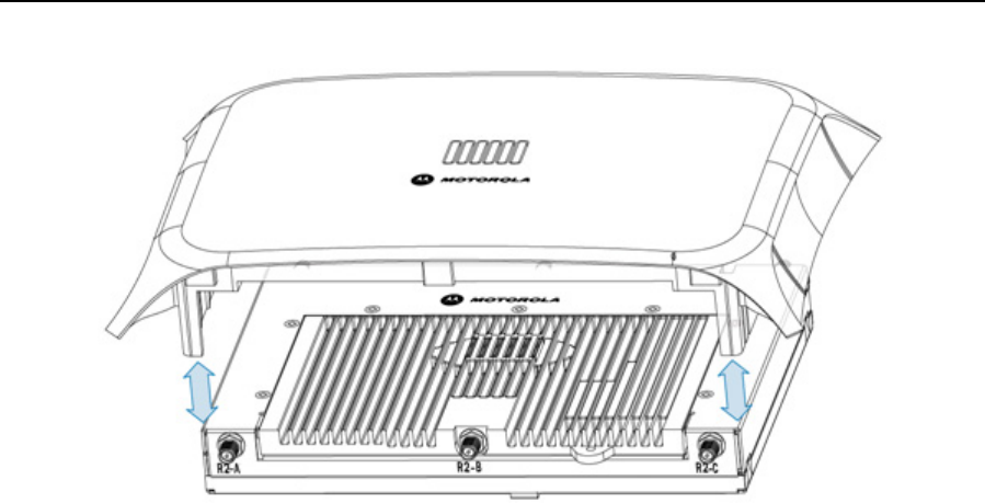
Both an AP7131 and AP7131N model Access Point have the following port designations:
• GE1/POE - LAN port
• GE2 - WAN Port
1. Verify the contents of the box includes the intended Access Point and accessory hardware.
2. Review site survey and network analysis reports to determine the location and mounting position for the
Access Point.
3. Connect a CAT-5 or better Ethernet cable to a PoE compatible device and run the cable to the installation
site. Ensure there is sufficient cable slack to perform the installation steps.
4. Determine whether the Access Point is powered using a Power Injector system, combining data and
power to the Access Point’s GE1/PoE port or will be powered from a conventional power adapter
providing power only to the Access Point’s DC-48V connector.
2.1 Precautions
Before installing an AP7131 or AP7131N model Access Point:
• Verify the intended deployment location is not prone to moisture or dust.
• Verify the environment has a continuous temperature range between 0° C to 40° C.
2.2 Package Contents
Check package contents for the correct model AP7131 and applicable AP7131 accessories. Each available
configuration (at a minimum), contains:
• AP7131 or AP7131N model Access Point (accessories dependent on SKU ordered)
• AP7131 Access Point Installation Guide (this guide, supporting both AP7131 and AP7131N models)
• Wall mount and screw and anchor kit
• Accessories Bag (4 rubber feet and a LED light pipe and badge with label for above the ceiling
installations)
Contact the Motorola Solutions Support Center to report missing or improperly functioning items.
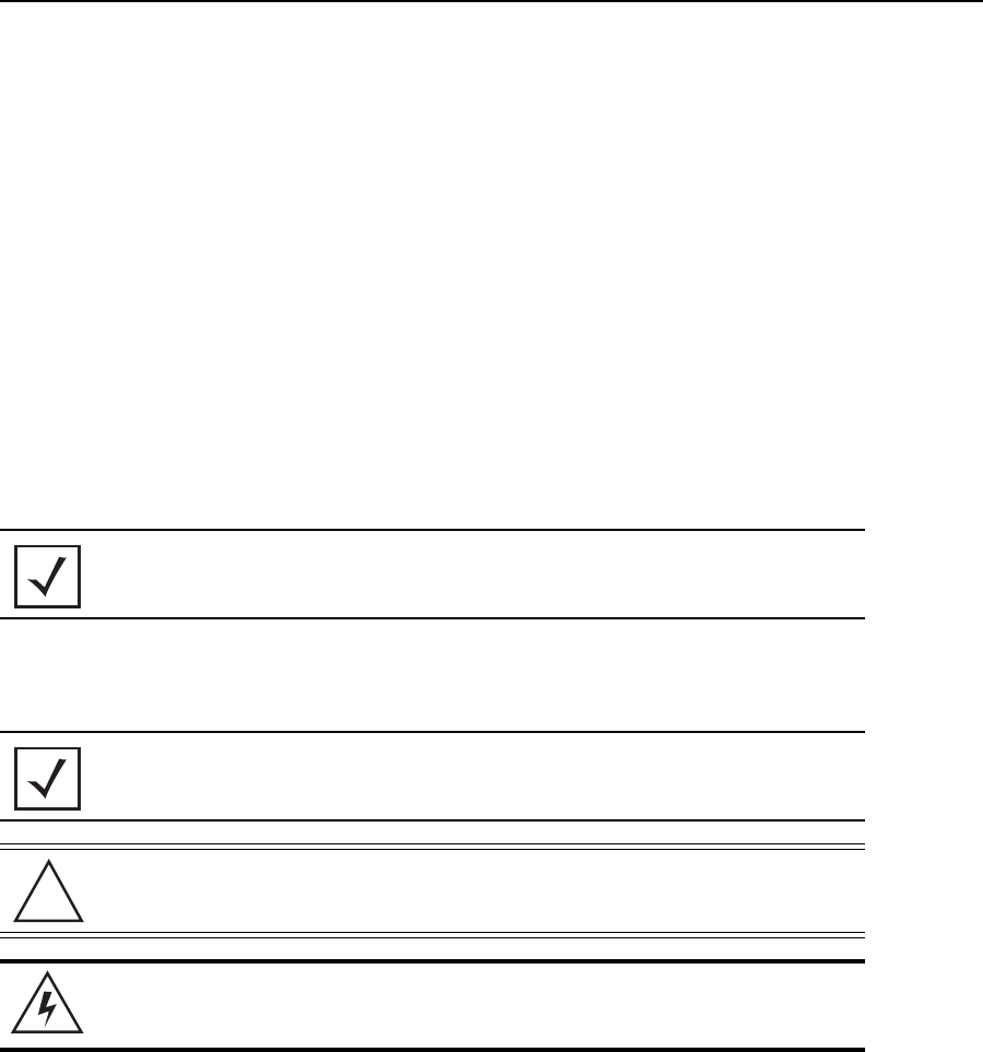
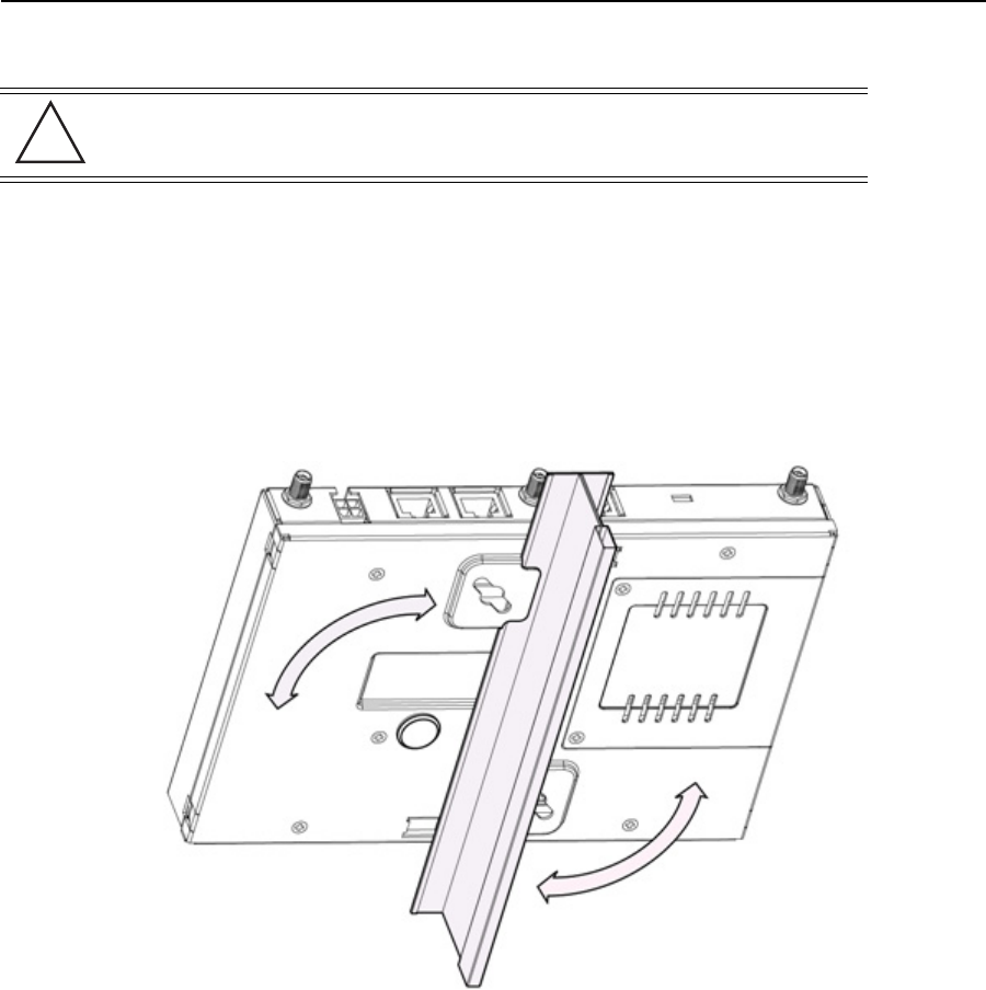
NOTE Some Access Points ship with a protective cover (facade) or a 6-element
MIMO antenna. The cover disconnects from the Access Point as
illustrated on the next page. When attached, LEDs continue to illuminate
through the cover.
8AP-7131 Access Point
2.3 Access Point Placement
For optimal performance, install the Access Point away from transformers, heavy-duty motors, fluorescent lights,
microwave ovens, refrigerators and other industrial equipment. Signal loss can occur when metal, concrete, walls
or floors block transmission. Install the Access Point in an open area or add Access Points as needed to improve
coverage.
Antenna coverage is analogous to lighting. Users might find an area lit from far away to be not bright enough. An
area lit sharply might minimize coverage and create dark areas. Uniform antenna placement in an area (like even
placement of a light bulb) provides even, efficient coverage.
Place the Access Point using the following guidelines:
• Install the Access Point at an ideal height of 10 feet from the ground.
• Orient the Access Point antennas vertically for best reception.
• Point the Access Point antennas downward if attaching to the ceiling (external antenna models only).
To maximize the Access Point’s radio coverage area, Motorola Solutions recommends conducting a site survey to
define and document radio interference obstacles before installing the Access Point.
Installation Guide 9
2.3.1 Antenna Options
Motorola Solutions supports two antenna suites for AP7131 and AP7131N models. One antenna suite supporting
the 2.4 GHz band and another antenna suite supporting the 5 GHz band. Select an antenna model best suited to the
intended operational environment of your Access Point. The AP7131N model Access Point can be purchased in a
three radio configuration. If a three radio SKU is purchased, the Access Point ships with a single antenna, factory
connected, to the Access Point chassis (next to the existing R1-A connector). This antenna is in addition to the other
six antennas available to the Access Point’s other two radios. The single antenna supporting the AP7131N’s third
radio supports sensor mode only and can not function as a WLAN radio.
Antenna connectors for single radio model Access Point are located on the same side of the Access Point as the
LAN and WAN port connections (GE1/POE and GE2). On single radio versions, the R-SMA connectors can support
both bands and should be connected to a R-SMA dual-band antenna or an appropriate single band antenna. If
necessary a R-SMA to R-BNC adapter (Part No. 25-72178-01) can be purchased separately from Motorola
Solutions.
R1 defines the Access Point’s radio 1 antenna connectors and R2 defines radio 2 antenna connectors.
Certain Rogue AP Detection features use a radio to perform dual-band scanning. The dedicated radio should be
connected to an appropriate dual-band dipole antenna (Part No. ML-2452-APA2-01).
10 AP-7131 Access Point
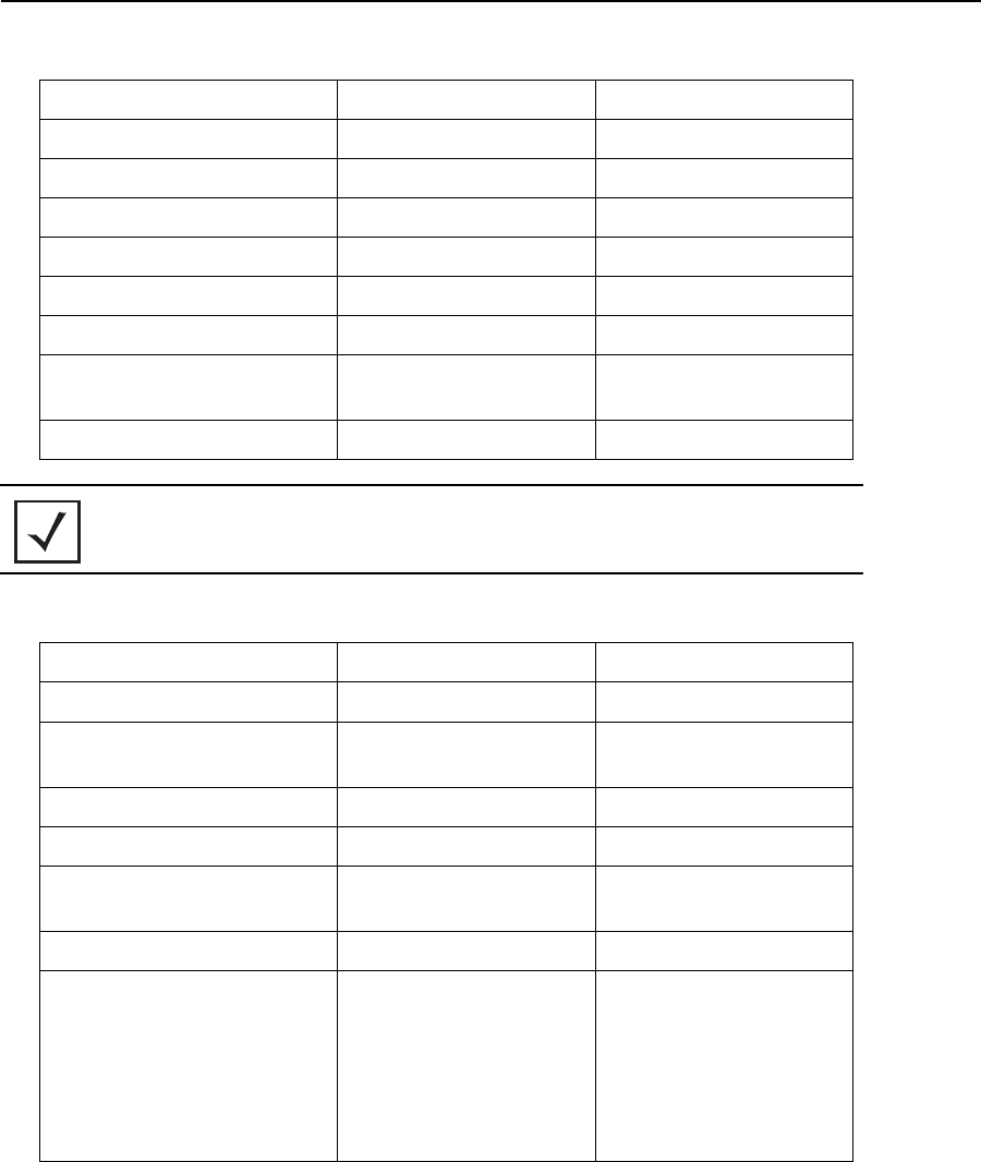
The 2.4 GHz antenna suite includes the following models:
The 5 GHz antenna suite includes the following models:
Part Number Antenna Type Approximate Gain (dBi)
ML-2499-11PNA2-01R Wide Angle Directional 8.5
ML-2499-HPA3-01R Omni-Directional Antenna 3.3
ML-2499-BYGA2-01R Yagi Antenna 13.9
ML-2499-BPNA3-01R Directional Panel 15.5
ML-2499-FHPA9-01R Dipole 10.5
ML-2452-APA2-01 Dual-Band 3/4
ML-2452-PTA2M3X3-1 Facade with 6 Element
Antenna Module
4.75/5.5
ML-2452-PTA3M3-036 3 Port MIMO Antenna 5/5
NOTE An additional adapter is required to use ML-2499-11PNA2-01R and
ML-2499-BYGA2-01R model antennas. Please contact Motorola
Solutions for more information.
Part Number Antenna Type Approximate Gain (dBi)
ML-5299-WPNA1-01R Panel Antenna 13
ML-5299-HPA1-01R Wide-Band Omni-Directional
Antenna
5.0
ML-5299-FHPA6-01R Omni-Directional Antenna 8.25
ML-2452-APA2-01 Dual-Band 3/4
ML-2452-PTA2M3X3-1 Facade with 6 Element
Antenna Module
4.75/5.5
ML-2452-PTA3M3-036 3 Port MIMO Antenna 5/5
ML-2452-APA6J-01 Dipole 2.4GHz Peak gain: -5.76dBi
5GHz Peak gain :
band 1: -3.77dBi
band 2: -3.38dBi
band 3: -2.84dBi
band 4: -2.94dBi
Installation Guide 11
For a more exhaustive overview of the antennas and associated components supported by the Motorola Solutions
Access Point family, refer to the Enterprise Wireless LAN Antenna Specification Guide available at
http://supportcentral.motorolasolutions.com/support/product/manuals.do.
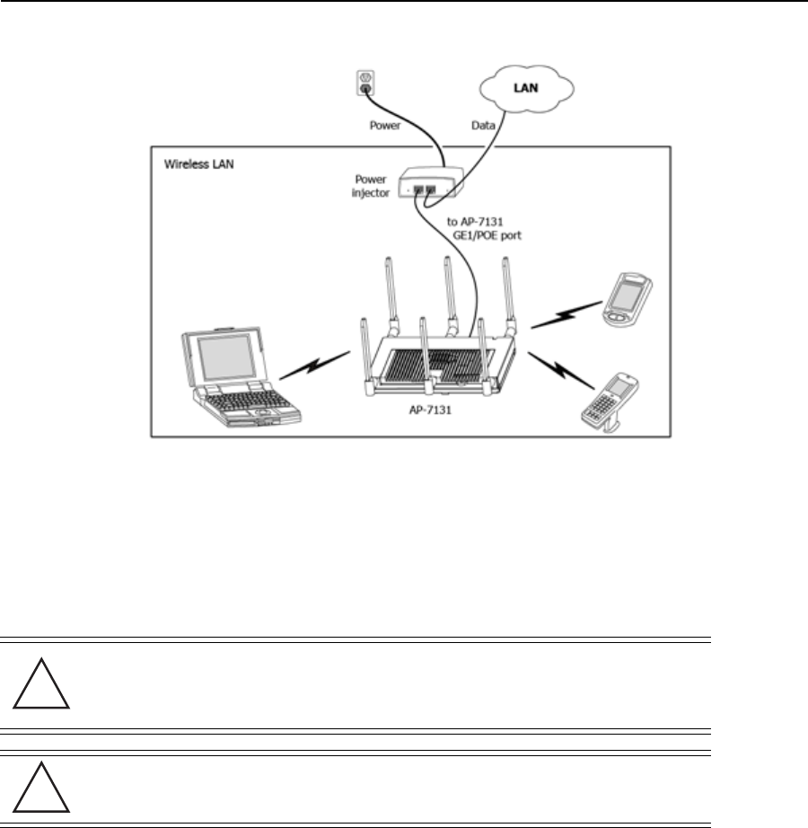
2.3.2 Power Injector System
The Access Point can receive power via an Ethernet cable connected to the GE1/PoE port.
When users purchase a WLAN solution, they often need to place Access Points in obscure locations. In the past, a
dedicated power source was required for each Access Point in addition to the Ethernet infrastructure. This often
required an electrical contractor to install power drops at each Access Point location. The Power Injector merges
power and Ethernet into one cable, reducing the burden of installation and allowing optimal Access Point
placement in respect to the intended coverage area.
The Power Injector (Part No. AP-PSBIAS-1P3-AFR) is a high power POE Injector delivering up to 30 watts. The
Access Point can only use a Power Injector when connecting the unit to the Access Point’s GE1/POE port. The Power
Injector is separately ordered and not shipped with an existing AP SKU.
An AP7131 and AP7131N can also be used with the 3af power injector (AP-PSBIAS-1P2-AFR). However, AP
functionality is limited when powered by an AP-PSBIAS-1P2-AFR, since the AP has Ethernet connectivity limited to
only the GE1 port.
The Motorola Solutions Access Point Power Supply (Part No. 50-14000-247R) is not included with the Access Point
and is orderable separately as an accessory. If the Access Point is providing both POE power over the GE1/POE
connection, as well as the 50-14000-247R power supply concurrently, the Access Point will source power from the
50-14000-247R supply only. Disconnecting AC power from the 50-14000-247R, causes the Access Point to re-boot
before sourcing power from the POE power injector. If the Access Point is operating using injector supplied power,
the Access Point will not automatically reboot if an AC adapter is connected. The Access Point continues to operate
with power supplied from the AC adapter without change to the Access Point’s operating configuration. If using
adapter supplied power and a change to the Access Point’s operating configuration is warranted (for example, if
needing to access the GE2 port), the Access Point needs to be manually rebooted by the customer.
NOTE Single radio model Access Points always operate using a full power
configuration. The power management configurations described in the table
below only apply to dual radio models. For detailed information on the power
management options available to the AP7131, refer to the Motorola Solutions
WiNG 5.4 Access Point System Reference Guide available at:
http://supportcentral.motorolasolutions.com/support/product/manuals.do.
CAUTION The Access Point supports any standards-based compliant power
source (including non-Motorola Solutions power sources). However,
using the wrong solution (including a POE system used on a legacy
Motorola Solutions Access Point) could either limit functionality or
severely damage the Access Point and void the product warranty.
!
12 AP-7131 Access Point
A separate Power Injector is required for each Access Point comprising the network.
The following guidelines should be adhered to before cabling the Power Injector to an Ethernet source and an
Access Point:
• Do not block or cover airflow to the Power Injector.
• Keep the Power Injector away from excessive heat, humidity, vibration and dust.
• The Power Injector isn’t a repeater, and does not amplify the Ethernet signal. For optimal performance,
ensure the Power Injector is placed as close as possible to the data port.
To install the Power Injector to an Ethernet data source and an Access Point:
1. Connect the Power Injector to an AC outlet (110VAC to 220VAC).
2. Connect an RJ-45 Ethernet cable between the network data supply (host) and the Power Injector Data In
connector.
CAUTION To avoid problematic performance and restarts, disable POE from a
wired controller port connected to an Access Point if mid-span power
sourcing equipment (PSE) is used between the two, regardless of the
manufacturer.
CAUTION Ensure AC power is supplied to the Power Injector using an AC cable
with an appropriate ground connection approved for the country of
operation.
!
!
Installation Guide 13
3. Connect an RJ-45 Ethernet cable between the Power Injector Data & Power Out connector and the Access
Point’s GE1/POE port.
Ensure the cable length from the Ethernet source (host) to the Power Injector and Access Point does not
exceed 100 meters (333 ft).
The Power Injector has no On/Off power switch. The Injector receives power and is ready for device
connection and operation as soon as AC power is applied. Refer to the Installation Guide shipped with the
Power Injector for a description of the device’s LEDs.
2.4 Mounting the Access Point
Both the AP7131 and AP7131N can attach to a wall, mount under a suspended T-Bar or above a ceiling (plenum or
attic) following the same installation instructions. Choose one of the following mounting options based on the
physical environment of the coverage area. Do not mount the Access Point in a location that has not been approved
in a site survey.
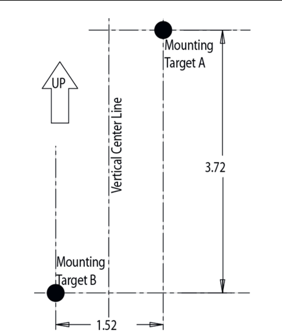
2.4.1 Wall Mounting
Wall mounting requires hanging the Access Point along its width (or length) using the pair of slots on the bottom
of the unit and the Access Point mounting template (on the next page) for the screws.
The hardware and tools (customer provided) required to install the Access Point on a wall consists of:
• Two Phillips (ANSI Standard Metric) M3.5 X 0.6 X 20mm Type D Self-Tapping screws: (ANSI Standard)
#6-18 X 0.875in. Type A or AB Self-Tapping screw, or (ANSI Standard Metric) M3.5 X 0.6 X 20mm Type D
Self-Tapping screw
• Two wall anchors
• Wall mount template (included on the next page
• Security cable (optional third part provided accessory)
NOTE Cabling a Power Injector to the WAN port (GE2 port) renders the Access
Point non-operational. Only use a AP-PSBIAS-1P3-AFR (or
AP-PSBIAS-1P2-AFR) Power Injector with the Access Point’s GE1/POE
(LAN) port.
CAUTION An Access Point should be wall mounted to concrete or
plaster-wall-board (dry wall) only. Do not wall mount the Access Point
to combustible surfaces.
!
14 AP-7131 Access Point
Installation Guide 15
To mount the Access Point on a wall using the provided template:
1. Copy the template (on the previous page) to a blank piece of paper. Do not reduce or enlarge the scale of
the template.
2. Tape the template to the wall mounting surface.
• If the installation requires the antenna be positioned vertically, the centerline reference (of the template)
needs to be positioned vertically. The cabling shall exit the Access Point in a vertical direction.
• If the installation requires the antenna be positioned horizontally, the vertical centerline (of the template)
needs to be positioned horizontally. The cabling shall exit the Access Point in a horizontal direction
3. At mounting targets A and B, mark the mounting surface through the template at the target center.
4. Discard the mounting template.
5. At each point, drill a hole in the wall, insert an anchor, screw into the anchor the wall mounting screw and
stop when there is 1mm between the screw head and the wall.
6. If pre-drilling a hole, the recommended hole size is 2.8mm (0.11in.) if the screws are going directly into
the wall and 6mm (0.23in.) if wall anchors are being used.
7. If required, install and attach a security cable to the Access Point lock port.
8. Attach the antennas to their correct connectors.
For information on available antennas, see Antenna Options.
9. Place the large center opening of each of the mount slots over the screw heads.
10. Slide the Access Point down along the mounting surface to hang the mount slots on the screw heads..
11. Cable the Access Point using either the Power Injector solution or an approved line cord and power supply.
NOTE If printing the mounting template (on the previous page) from an
electronic PDF, dimensionally confirm the template by measuring each
value for accuracy.
CAUTION Ensure you are placing the antennas on the correct connectors
(depending on your single or dual-radio model and frequency used) to
ensure the successful operation of the Access Point.
NOTE It is recommended the Access Point be mounted with the RJ45 cable
connector oriented upwards or downwards to ensure proper operation.
!

16 AP-7131 Access Point
For Motorola Power Injector installations:
a. Connect an RJ-45 CAT5 Ethernet cable between the network data supply (host) and the Power
Injector’s Data In connector.
b. Connect an RJ-45 CAT5 Ethernet cable between the Power Injector’s Data & Power Out connector
and the Access Point’s GE1/POE ports.
c. Ensure the cable length from the Ethernet source (host) to the Power Injector and Access Point does
not exceed 100 meters (333 ft). The Power Injector has no On/Off power switch. The Power Injector
receives power as soon as AC power is applied. For more information, see Power Injector System.
For standard power adapter (non Power Injector) and line cord installations:
a. Connect a RJ-45 CAT5e (or CAT6) Ethernet cable between the network data supply (host) and the
Access Point’s GE1/PoE.
b. Verify the power adapter is correctly rated according the country of operation.
c. Connect the power supply line cord to the power adapter.
d. Attach the power adapter cable to the DC-48V power connector on the Access Point.
e. Attach the power supply line cord to a power supply.
12. Verify the behavior of the Access Point LEDs. For more information, see LED Indicators.
13. The Access Point is ready to configure. For information on basic Access Point device configuration, see
Basic Access Point Configuration.
CAUTION Do not actually connect to the power source until the cabling portion
of the installation is complete
!

Installation Guide 17
2.4.2 Suspended Ceiling T-Bar Installation
A suspended ceiling mount requires holding the Access Point up against the T-bar of a suspended ceiling grid and
twisting the Access Point chassis onto the T-bar.
The mounting tools (customer provided) and hardware required to install the Access Point on a ceiling T-bar consists
of:
• Safety wire (recommended and customer supplied)
• Security cable (optional and customer supplied).
To install the Access Point on a ceiling T-bar:
1. Motorola Solutions recommends you loop a safety wire — with a diameter of at least 1.01 mm (.04 in.),
but no more than 0.158 mm (.0625 in.) — through the tie post (above the Access Point’s console connector)
and secure the loop.
2. If desired, install and attach a security cable to the Access Point lock port.
3. Attach the antennas to their correct connectors.
For more information on the antenna options available to the Access Point, see Antenna Options.
4. Cable the Access Point using either the Power Injector solution or an approved line cord and power supply.
For Motorola Power Injector installations:
a. Connect an RJ-45 CAT5 Ethernet cable between the network data supply (host) and the Power
Injector’s Data In connector.
b. Connect an RJ-45 CAT5 Ethernet cable between the Power Injector’s Data & Power Out connector
and the Access Point’s GE1/POE port.
c. Ensure the cable length from the Ethernet source (host) to the Power Injector and Access Point does
not exceed 100 meters (333 ft). The Power Injector has no On/Off power switch. The Power Injector
receives power as soon as AC power is applied. For more information, see Power Injector System.
For standard power adapter (non Power Injector) and line cord installations:
a. Connect a RJ-45 CAT5e (or CAT6) Ethernet cable between the network data supply (host) and the
Access Point’s GE1/PoE or GE2 port.
b. Verify the power adapter is correctly rated according the country of operation.
c. Connect the power supply line cord to the power adapter.
d. Attach the power adapter cable into the power connector on the Access Point.
CAUTION Ensure you are placing the antennas on the correct connectors
(depending on your single or dual-radio model and frequency used) to
ensure the successful operation of the Access Point.
!
18 AP-7131 Access Point
e. Attach the power supply line cord to a power supply.
5. Verify the behavior of the Access Point LEDs. For more information, see For more information, see LED
Indicators.
6. Align the bottom of the ceiling T-bar with the back of the Access Point.
7. Orient the Access Point chassis by its length and the length of the ceiling T-bar.
8. Rotate the Access point chassis 45 degrees clockwise.
9. Push the back of the Access Point chassis on to the bottom of the ceiling T-bar.
10. Rotate the Access Point chassis 45 degrees counter-clockwise. The clips click as they fasten to the T-bar.
11. The Access Point is ready to configure. For information on basic Access Point device configuration, see
Basic Access Point Configuration.
CAUTION Do not actually connect to the power source until the cabling portion
of the installation is complete
!
Installation Guide 19
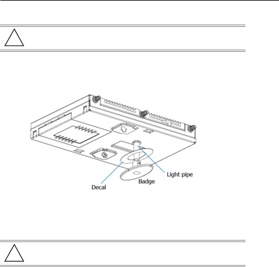
2.4.3 Above the Ceiling (Plenum) Installation
An above the ceiling installation requires placing the Access Point above a suspended ceiling and installing the
provided light pipe under the ceiling tile for viewing the rear panel status LEDs of the unit. An above the ceiling
installation enables installations compliant with drop ceilings, suspended ceilings and industry standard tiles from
.625 to .75 inches thick.
The mounting hardware required to install the Access Point above a ceiling consists of:
• Light pipe
• Badge for light pipe
• Decal for badge
• Safety wire (strong recommended)
• Security cable (optional)
To install the Access Point above a ceiling:
1. If possible, remove the adjacent ceiling tile from its frame and place it aside.
2. If required, install a safety wire, between 1.5mm (.06in.) and 2.5mm (.10in.) in diameter, in the ceiling
space.
3. If required, install and attach a security cable to the Access Point’s lock port.
4. Mark a point on the finished side of the tile where the light pipe is to be located.
5. Create a light pipe path hole in the target position on the ceiling tile.
NOTE Both the AP7131 and AP7131N are Plenum rated to UL2043 and NEC1999
to support above the ceiling installations. To ensure UL compliance and
proper Access Point operation within the Air Handling Plenum, the
Access Point must be installed with the bottom surface of the unit in
contact with the un-finished surface of the ceiling tile. This will facilitate
the positioning of the light pipe (described in the following pages)
through the ceiling tile.
CAUTION Motorola Solutions does not recommend mounting the Access Point
directly to any suspended ceiling tile with a thickness less than
12.7mm (0.5in.) or a suspended ceiling tile with an unsupported span
greater than 660mm (26in.). Motorola Solutions strongly recommends
fitting the Access Point with a safety wire suitable for supporting the
weight of the device. The safety wire should be a standard ceiling
suspension cable or equivalent steel wire between 1.59mm (.062in.)
and 2.5mm (.10in.) in diameter.
NOTE Remove the Access Point’s facade and antennas before installing in an
above the ceiling orientation. The Access Point is not certified for an
above the ceiling installation with its accessories installed.
!
20 AP-7131 Access Point
6. Use a drill to make a hole in the tile the approximate size of the Access Point LED light pipe.
7. Remove the light pipe’s rubber stopper (from the Access Point) before installing the light pipe.
8. Connect the light pipe to the bottom of the Access Point. Align the tabs and rotate approximately 90
degrees. Do not over tighten.
9. Fit the light pipe into hole in the tile from its unfinished side.
10. Place the decal on the back of the badge and slide the badge onto the light pipe from the finished side of
the tile.
11. Attach the antennas to their correct connectors.
For information on the antennas available to the Access Point, see Antenna Options.
12. Motorola Solutions recommends attaching safety wire to the Access Point safety wire tie point or security
cable (if used) to the Access Point’s lock port.
13. Align the ceiling tile into its former ceiling space
14. Cable the Access Point using either the Power Injector solution or an approved line cord and power supply.
CAUTION Motorola Solutions recommends care be taken not to damage the
finished surface of the ceiling tile when creating the light pipe hole
and installing the light pipe.
CAUTION Ensure you are placing the antennas on the correct connectors
(depending on your single or dual-radio model and frequency used) to
ensure the successful operation of the Access Point.
!
!

Installation Guide 21
For Motorola Power Injector installations:
a. Connect an RJ-45 CAT5 Ethernet cable between the network data supply (host) and the Power
Injector’s Data In connector.
b. Connect an RJ-45 CAT5 Ethernet cable between the Power Injector’s Data & Power Out connector
and the Access Point’s GE1/POE port.
c. Ensure the cable length from the Ethernet source (host) to the Power Injector and Access Point does
not exceed 100 meters (333 ft). The Power Injector has no On/Off power switch. The Power Injector
receives power as soon as AC power is applied. For more information, see Power Injector System.
For standard power adapter (non Power Injector) and line cord installations:
a. Connect a RJ-45 CAT5e (or CAT6) Ethernet cable between the network data supply (host) and the
Access Point’s GE1/PoE or GE2 port.
b. Verify the power adapter is correctly rated according the country of operation.
c. Connect the power supply line cord to the power adapter.
d. Attach the power adapter cable into the power connector on the Access Point.
e. Attach the power supply line cord to a power supply.
15. Verify the behavior of the Access Point LED light pipe. For more information, see
LED Indicators.
16. Place the ceiling tile back in its frame and verify it is secure.
17. The Access Point is ready to configure. For information on basic Access Point device configuration, see
Basic Access Point Configuration.
CAUTION Do not actually connect to the power source until the cabling portion
of the installation is complete
!
22 AP-7131 Access Point
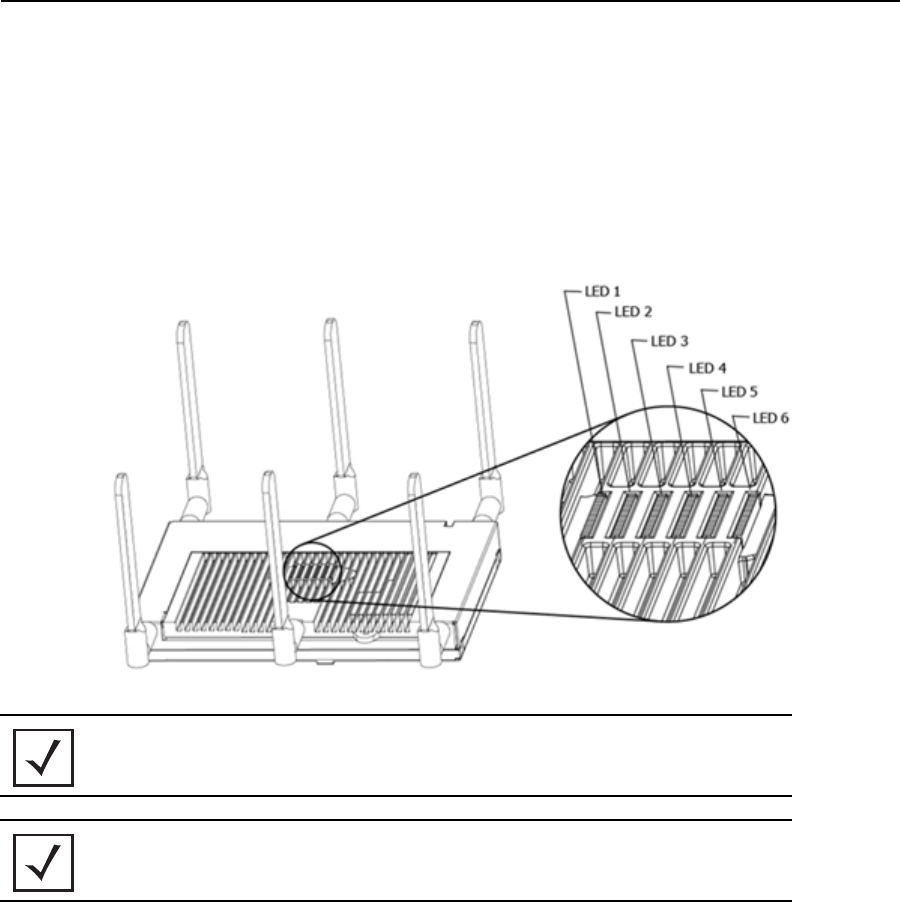
2.5 LED Indicators
Both AP7131 and AP7131N model Access Point have six LEDs on the top of the Access Point housing, and one
optional LED light pipe at the bottom of the unit. However, an AP7131 model Access Point does not use LED 6, as
no third radio is available. Five LEDs illuminate (on top of the housing) for dual radios models and four illuminate
for single radio models.
The Access Point utilizes two (different colored) lights below each LED. Only one light displays within a LED at any
given time. Every light within each LED is exercised during startup to allow the user to see if an LED is
non-functional. The LEDs turn on and off while rotating around in a circle. Since two LEDs feed each light pipe, the
pattern is from left to right, then right to left.
The LEDs on the top housing of the Access Point are clearly visible in wall and below ceiling installations. The top
housing LEDs have the following display and functionality:
NOTE The LED blink rate is proportional to activity. The busiest traffic
corresponds to the fastest blink, while the slowest traffic corresponds to
slowest blink.
NOTE Depending on how the 5 GHz and 2.4 GHz radios are configured, the LEDs
will blink at different intervals between amber and yellow (5 GHz radio)
and emerald and yellow (2.4 GHz radio).

Installation Guide 23
2.5.1 Three Radio AP7131 LEDs
A three radio model AP7131N Access Point has the following unique LED behavior:
2.5.2 Dual Radio (2.4/5 GHz) LEDs
A dual radio model Access Point has the following unique LED behavior:
LED 1 LED 2 (LAN) LED 3 (WAN) LED 4 - 5 GHz LED 5 - 2.4 GHz LED 6
Blinking Red
indicates booting.
Solid Red defines
the diagnostic
mode.
White defines
normal operation.
Blinking Green
indicates normal
GE1 operation.
Blinking Yellow
indicates port error.
Blinking Green
indicates normal
GE2 operation.
Blinking Yellow
indicates port error.
Amber is on when
the radio is
configured for
802.11a/n. Blinking
Amber indicates
radio activity. When
functioning as a
sensor, LED
alternates between
Amber and Yellow.
The blink interval is
1 second. When no
Server is connected,
the Yellow LED is
always on.
Emerald is on when
the radio is
configured for
802.11bgn. Blinking
Emerald indicates
radio activity. When
functioning as a
sensor, LED
alternates between
Emerald and
Yellow. The blink
interval is 1 second.
When no Server is
connected, the
Yellow LED is
always on.
Amber indicates
that the radio is
defined as a sensor,
but is not
connected to server.
Alternates between
Emerald and
Amber when the
radio is defined as a
sensor and a server
is connected. The
blink interval is 1
second.
LED 1 LED 2 (LAN) LED 3 (WAN) LED 4 - 5 GHz LED 5 - 2.4 GHz LED 6
Blinking Red
indicates booting.
Solid Red defines
the diagnostic
mode.
White defines
normal operation.
Blinking Green
indicates normal
GE1 operation.
Blinking Yellow
indicates port error.
Blinking Green
indicates normal
GE2 operation.
Blinking Yellow
indicates port error.
Amber is on when
the radio is
configured for
802.11a/n. Blinking
Amber indicates
radio activity. When
functioning as a
sensor, LED
alternates between
Amber and
Yellow. The blink
interval is 1 second.
When no Server is
connected, the
Yellow LED is
always on.
Emerald is on
when the radio is
configured for
802.11bgn. Blinking
Emerald indicates
radio activity. When
functioning as a
sensor, LED
alternates between
Emerald and
Yellow. The blink
interval is 1 second.
When no Server is
connected, the
Yellow LED is
always on.
Not Used

24 AP-7131 Access Point
2.5.3 Single Radio 2.4 GHz LEDs
A single 2.4 GHz radio model Access Point has the following unique LED behavior:
2.5.4 Single Radio 5 GHz LEDs
A single 5 GHz radio model Access Point has the following unique LED behavior:
LED 1 LED 2 (LAN) LED 3 (WAN) LED 4 - 5 GHz LED 5 - 2.4 GHz LED 6
Blinking Red
indicates booting.
Solid Red defines
the diagnostic
mode.
White defines
normal operation.
Blinking Green
indicates normal
GE1 operation.
Blinking Yellow
indicates port error.
Blinking Green
indicates normal
GE2 operation.
Blinking Yellow
indicates port error.
Off Emerald is on
when the radio is
configured for
802.11bgn. Blinking
Emerald indicates
radio activity. When
functioning as a
sensor, LED
alternates between
Emerald and
Yellow. The blink
interval is 1 second.
When no Server is
connected, the
Yellow LED is
always on.
Not Used
LED 1 LED 2 LED 3 LED 4 - 5 GHz LED 5 - 2.4 GHz LED 6
Blinking Red
indicates booting.
Solid Red defines
the diagnostic
mode.
White defines
normal operation.
Blinking Green
indicates normal
GE1 operation.
Blinking Yellow
indicates port error.
Blinking Green
indicates normal
GE2 operation.
Blinking Yellow
indicates port error.
Amber is on when
the radio is
configured for
802.11a/n. Blinking
Amber indicates
radio activity. When
functioning as a
sensor, LED
alternates between
Amber and
Yellow. The blink
interval is 1 second.
When no Server is
connected, the
Yellow LED is
always on.
Off Not Used

Installation Guide 25
2.5.5 Rear AP7131 LED
The LED on the rear (bottom) of the Access Point is optionally viewed using a single (customer installed) extended
light pipe, adjusted as required to suit above the ceiling installations. The LED light pipe has the following color
display and functionality:
LED 7
Blinking Red (160 msec) indicates a failure condition.
Solid Red defines the diagnostic mode.
White defines normal operation.
26 AP-7131 Access Point
3 Basic Access Point Configuration
Once the Access Point is installed and powered on, complete the following steps to get the device up and running
and access management functions:
1. Attach an Ethernet cable from the Access Point to a controller with an 802.3af compatible power source
or use the PWRS-14000-148R power supply to supply power to the Access Point (once fully cabled).
If your host system is a DHCP server, an IP address is automatically assigned to the Access Point and can
be used for device connection. However, if a DHCP server is not available, you’ll need to derive the IP
address from the Access Point MAC address. Using this method, the last two bytes of the MAC address
become the last two octets of the IP address. For example:
MAC address - 00:C0:23:00:F0:0A
Zero-Config IP address - 169.254.240.10
To derive the Access Point’s IP address using its MAC address:
a. Open the Windows calculator be selecting Start > All Programs > Accessories > Calculator. This menu
path may vary slightly depending on your version of Windows.
b. With the Calculator displayed, select View > Scientific. Select the Hex radio button.
c. Enter a hex byte of the Access Point’s MAC address. For example, F0.
d. Select the Dec radio button. The calculator converts F0 into 240. Repeat this process for the last
Access Point MAC address octet.
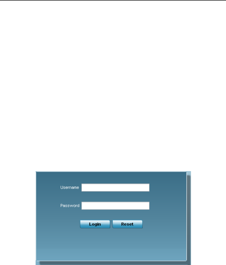
2. Point the Web browser to the Access Point’s IP address. The following login screen displays.
3. Enter the default username admin in the Username field.
4. Enter the default password motorola in the Password field.
Installation Guide 27
5. Click the Login button to load the management interface.
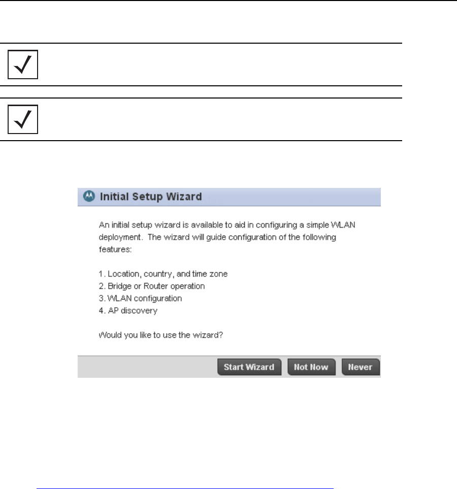
6. If this is the first time the management interface has been accessed, a dialogue displays allowing an
administrator to define whether a ty[ical setup or advancd setup is conducted.
For the purposes of this guide, use the Typical Setup (Recommended) option to simply the process of
getting the Access Point up and running quickly with a minimum number of changes to the Access Point’s
default configuration.
For information on using the Access Point’s Advanced Setup option, refer to the WiNG Access Point
System Reference Guide to familiarize yourself with the feature set supported by the WiNG operating
system. The guide is available at
http://supportcentral.motorolasolutions.com/support/product/manuals.do.
NOTE When logging in for the first time, you’re prompted to change the
password to enhance device security in subsequent logins.
NOTE If you get disconnected when running the wizard, you can connect again
with the Access Point’s actual IP address (once obtained) and resume the
wizard.
28 AP-7131 Access Point
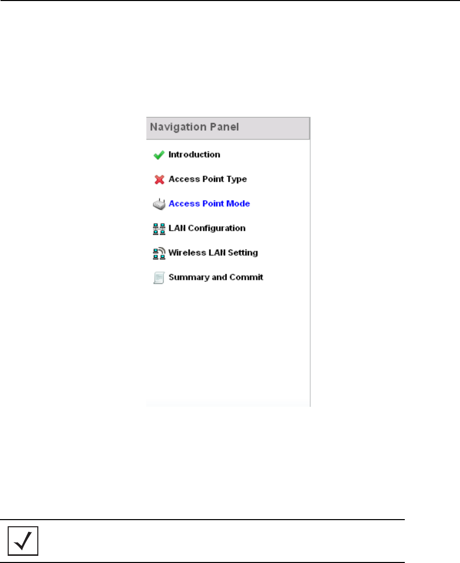
The Initial Setup Wizard displays a Navigation Panel on the left-hand side of each screen to assist the
administrator in assessing which tasks still require completion before the Access Point can be deployed
into service.
A green checkmark to the left of an item in the Navigation Panel defines the task as having its minimum
required configuration set correctly. A red X defines a task as still requiring at least one parameter be
defined correctly.
The tasks populating the Navigation Panel differ depending on whether a Typical Setup (Recommended)
or Advanced Setup is selected as the setup option. Select Save/Commit within each page to save the
updates made to that page's configuration. Select Next to proceed to the next page listed in the
Navigation Panel. Select Back to revert to the previous screen in the Navigation Panel without saving your
updates. The Introduction screen displays a list of the basic configuration activities supported by the Initial
Setup Wizard.
NOTE While you can navigate to any page in the navigation panel, you cannot
complete the Initial AP Setup Wizard until each task in the Navigation
Panel has a green checkmark.
Installation Guide 29
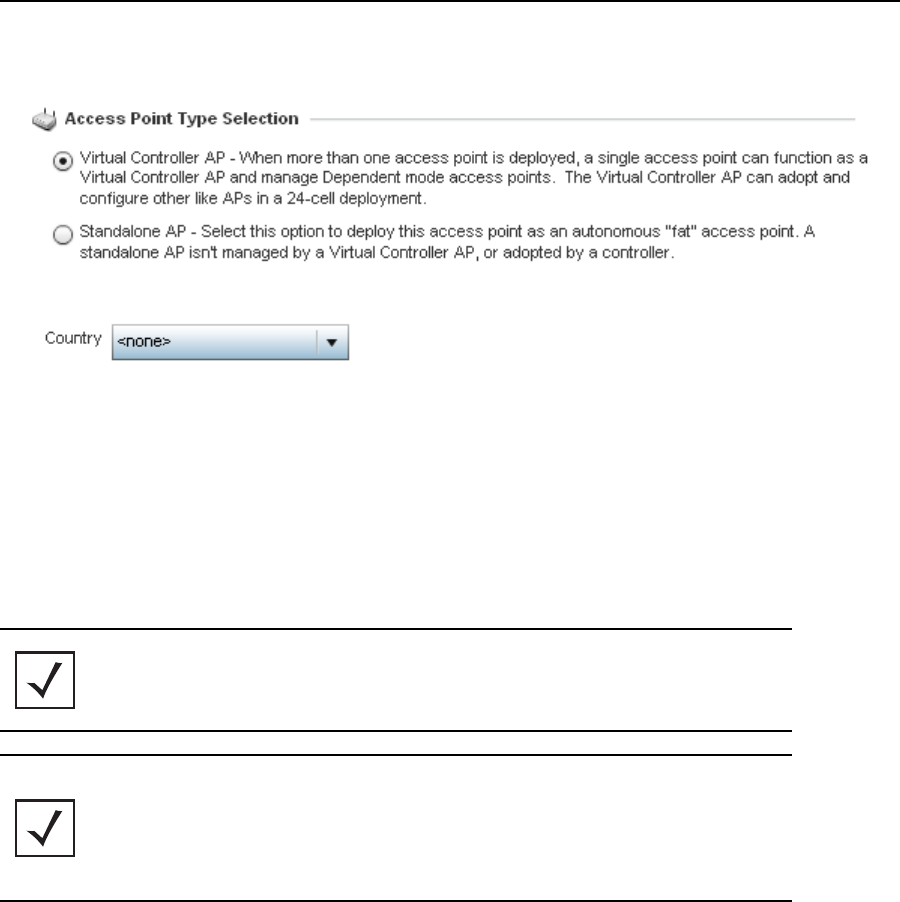
7. Select Next. The Initial AP Setup Wizard displays the Access Point Type screen to define the Access
Point's Standalone versus Virtual Controller AP functionality,
8. Select an Access Point Type from the following options:
•Virtual Controller AP - When more than one Access Point is deployed, a single Access Point can
function as a Virtual Controller AP. Up to 24 Access Points can be connected to, and managed by, a
single Virtual Controller AP of the same model.
•Standalone AP -Select this option to deploy this Access Point as an autonomous fat Access Point. A
Standalone AP isn't managed by a Virtual Controller AP, or adopted by a controller.
9. Use the Country drop-down menu to set where the Access Point is deployed.
The Access Point prompts for the correct country code on the first login. A warning message also displays
stating an incorrect country setting may result in illegal radio operation. Selecting the correct country is
central to legal operation. Each country has its own regulatory restrictions concerning electromagnetic
emissions and the maximum RF signal strength that can be transmitted. This is a required parameter.
NOTE If wanting to adopt the Access Point to a controller or service platform.
Use the controller or service platform’s resident UI to connect to the
Access Point, provision its configuration and administrate the Access
Point’s configuration.
NOTE If designating the Access Point as a Standalone AP, Motorola Solutions
recommends the Access Point’s UI be used exclusively to define its
device configuration, and not the CLI. The CLI provides the ability to
define more than one profile and the UI does not. Consequently, the two
interfaces cannot be used collectively to manage profiles without an
administrator encountering problems.
30 AP-7131 Access Point
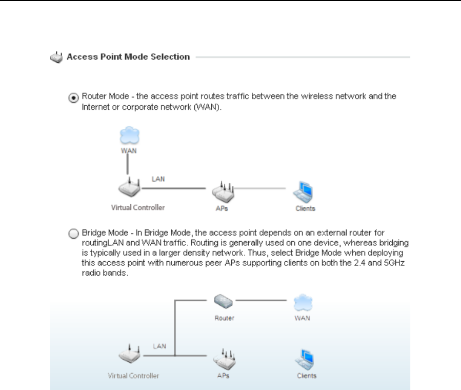
10. Select Next. The Initial Setup Wizard displays the Access Point Mode screen to define the Access
Point's routing or bridging mode functionality.
11. Select an Access Point Mode from the available options:
•Router Mode -the Access Point routes traffic between the local network (LAN) and the Internet or
external network (WAN). Router mode is recommended in a deployment supported by just a single
Access Point. When Router Mode is selected, an additional WAN screen is available in the wizard
screen flow to configure interface settings for the Access Point’s WAN port.
•Bridge Mode - n Bridge Mode, the AP depends on an external router for routing LAN and WAN traffic.
Routing is generally used on one device, whereas bridging is typically used in a larger network. Thus,
select Bridge Mode when deploying this Access Point with numerous peer APs supporting clients on
both the 2.4 and 5GHz radio bands.
Installation Guide 31
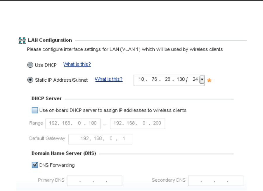
12. Select Next. The Initial AP Setup Wizard displays the LAN Configuration screen to set the Access
Point's LAN interface configuration.
13. Set the following DHCP and Static IP Address/Subnet information for the LAN interface:
•Use DHCP - Select the checkbox to enable an automatic network address configuration using the
Access Point’s DHCP server.
•Static IP Address/Subnet - Enter an IP Address and a subnet for the Access Point's LAN interface. If
Use DHCP is selected, this field is not available. When selecting this option, define the following DHCP
Server and Domain Name Server (DNS) resources, as those fields will become enabled on the bottom
portion of the screen.
•Use on-board DHCP server to assign IP addresses to wireless clients -Select the checkbox to
enable the Access Point’s DHCP server to provide IP and DNS information to clients on the LAN
interface.
•Range - Enter a starting and ending IP Address range for client assignments on the LAN interface.
Avoid assigning IP addresses from x.x.x.1 - x.x.x.10 and x.x.x.255, as they are often reserved for
standard network services. This is a required parameter.
•Default Gateway - Define a default gateway address for use with the default gateway. This is a
required parameter.
32 AP-7131 Access Point
•DNS Forwarding - Select this option to allow a DNS server to translate domain names into IP
addresses. If this option is not selected, a primary and secondary DNS resource must be specified.
DNS forwarding is useful when a request for a domain name is made but the DNS server, responsible
for converting the name into its corresponding IP address, cannot locate the matching IP address.
•Primary DNS - Enter an IP Address for the main Domain Name Server providing DNS services for
the Access Point's LAN interface.
•Secondary DNS - Enter an IP Address for the backup Domain Name Server providing DNS services
for the Access Point's LAN interface.
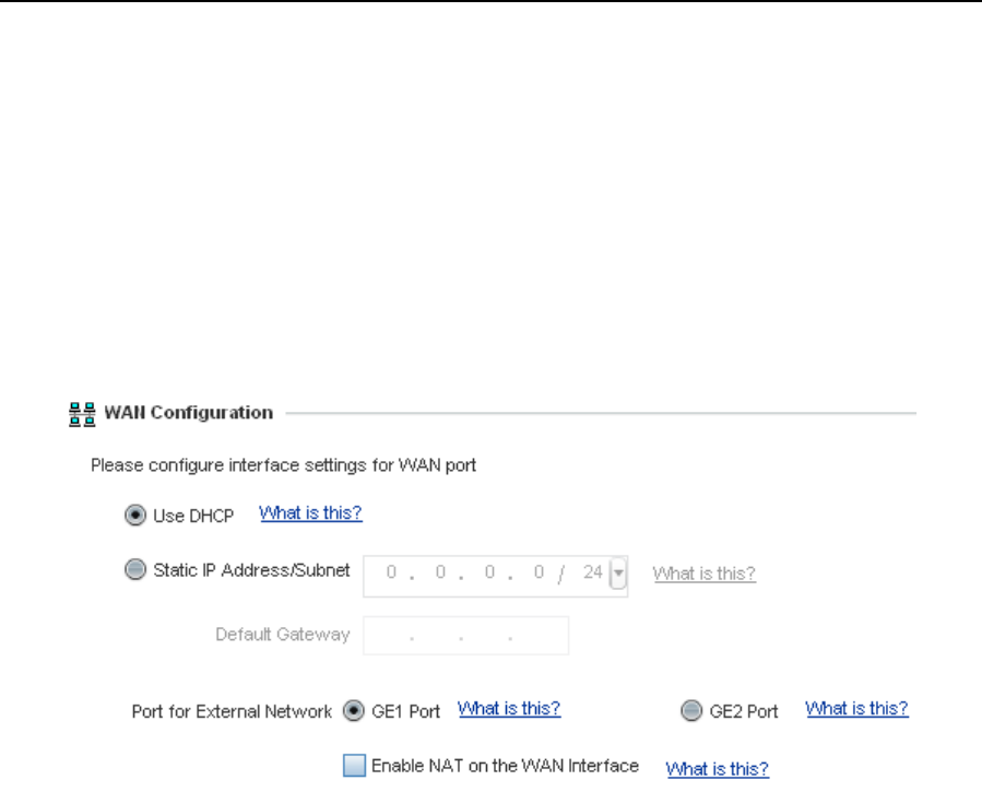
14. Select Next. If Router was selected as the Access Point mode the Initial Setup Wizard displays the WAN
Configuration screen. If Bridge was selected, the wizard proceeds to the Summary and Commit
screen.
15. Set the following DHCP and Static IP Address/Subnet information to define how the Access Point routes
traffic between the local network (LAN) and the Internet or external network (WAN):
•Use DHCP - Select the checkbox to enable an automatic network address configuration using the
Access Point’s DHCP server.
•Static IP Address/Subnet - Enter an IP Address/Subnet and gateway for the Access Point's WAN
interface. These are required fields.
•Port for External Network - Select the port used as the physical Access Point connection to the external
network. The ports available differ depending on the Access Point model deployed. Access point
models with a single port have this option fixed.
•Enable NAT on the WAN Interface - Select the checkbox to allow traffic to pass between the Access
Point's WAN and LAN interfaces.
Installation Guide 33
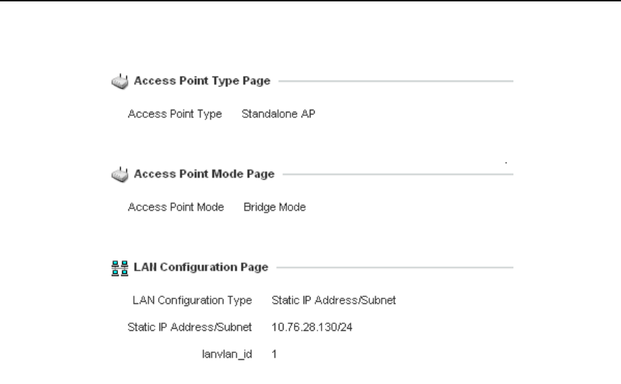
16. Select Next. The Initial AP Setup Wizard displays the Summary and Commit screen to summarize the
screens (pages) and settings updated using the Initial Setup Wizard.
No user intervention or additional settings are required within this screen. Its an additional means of
validating the Access Point’s updated configuration before its deployed. However, if a screen displays
settings not intended as part of the initial configuration, then any screen can be selected again from
within the Navigation Panel and its settings modified accordingly.
17. If the configuration displays as intended, select the Save/Commit button to implement these settings to
the Access Point’s configuration. If additional changes are warranted based on the summary, either select
the target page from the Navigational Panel, or use the Back and Next buttons to scroll to the target
screen.

34 AP-7131 Access Point
4 Specifications
4.1 AP7131 Physical Characteristics
An AP7131 model Access Point has the following physical characteristics:
4.2 AP7131N Physical Characteristics
An AP7131N model Access Point has the following physical characteristics:
Dimensions 5.50 in. Depth x 7.88 in. Width x 1.10 in. Height
14 cm Depth x 20.32 cm Width x 2.79 cm Height
Housing Metal, plenum-rated housing (UL2043)
Weight 2.22 lbs
Operating
Temperature
-4°F to 122°F/-20°C to 50°C
Storage Temperature -40°F to 158°F/-40°C to 70°C
Humidity 5 to 95% RH non-condensing
Electrostatic
Discharge
15kV air, 8kV contact
Dimensions 5.50 in. Depth x 7.88 in. Width x 1.38 in. Height
14 cm Depth x 20.32 cm Width x 3.5 cm Height
Housing Metal, plenum-rated housing (UL2043)
Weight 2.7 lbs

Installation Guide 35
4.3 Electrical Characteristics
The AP7131 and AP7131N model Access Points have the following electrical characteristics:
4.4 AP7131 Radio Characteristics
An AP7131 model Access Point has the following radio characteristics:
Operating Voltage 48VDC (compatible with POE .3af/.3at Draft)
Operating Current Not to exceed 750mA @ 48VDC
Power 48VDC, 0.75A
Operating Channels All channels from 4920 MHz to 5825 MHz except channel
52 -64
Channels 1-13 (EU), Channels 1-11 (US/Canada)
Channel 14 (2484 MHz) Japan only
Actual operating frequencies depend on regulatory
Data Rates Supported 802.11g: 1,2,5.5,11,6,9,12,18,24,36,48, and 54Mbps
802.11a: 6,9,12,18,24,36,48, and 54Mbps
802.11n: MCS 0-15 up to 300Mbps
Wireless Medium Direct Sequence Spread Spectrum (DSSS),
Orthogonal Frequency Division Multiplexing (OFDM)
Spatial multiplexing (MIMO)
Network Standards 802.11a, 802.11b, 802.11g, 802.3, 802.11n (Draft 2.0)
Maximum Available
Transmit Power
20dBm
Transmit Power
Adjustment
1dB increments
Antenna
Configuration
2x3 or 3x3

36 AP-7131 Access Point
4.5 AP7131N Radio Characteristics
An AP7131N model Access Point has the following radio characteristics:
Operating Channels All channels from 4920 MHz to 5825 MHz except channel
52 -64
Channels 1-13 (EU), Channels 1-11 (US/Canada)
Channel 14 (2484 MHz) Japan only
Actual operating frequencies depend on regulatory
Data Rates Supported 802.11g: 1,2,5.5,11,6,9,12,18,24,36,48, and 54Mbps
802.11a: 6,9,12,18,24,36,48, and 54Mbps
802.11n: MCS 0-15 up to 300Mbps
Wireless Medium Direct Sequence Spread Spectrum (DSSS),
Orthogonal Frequency Division Multiplexing (OFDM)
Spatial multiplexing (MIMO)
Network Standards 802.11a, 802.11b, 802.11g, 802.3, 802.11n (Draft 2.0)
Maximum Available
Transmit Power
Maximum available conducted transmit power per chain: 2.4Ghz: + 23dBm
Maximum available conducted transmit power all chains: 2.4GHz: + 27.7dBm
Maximum available conducted transmit power per chain: 5.2Ghz: + 20 dBm
Maximum available conducted transmit power all chains: 5.2GHz: + 24.7dBm
Transmit Power
Adjustment
1dB increments
Antenna
Configuration
2x3 or 3x3

Installation Guide 37
5 Regulatory Information
5.1 Regulatory Overview
These devices (AP-7131 and AP-7131N) are approved under Motorola Solutions, Inc.
All Motorola Solutions devices are designed to be compliant with rules and regulations in locations they are sold
and will be labeled as required. Any changes or modifications to Motorola Solutions equipment, not expressly
approved by Motorola Solutions, could void the user's authority to operate the equipment.
Local language translations are available at the following website:
http://supportcentral.motorolasolutions.com/support/product/manuals.do.
Any changes or modifications to Motorola Solutions equipment, not expressly approved by Motorola Solutions,
could void the user’s authority to operate the equipment.
Motorola Solutions Access Points must be professionally installed and configured so that the Radio Frequency
Output Power will not exceed the maximum allowable limit for the country of operation.
Antennas: Use only the supplied or an approved replacement antenna. Unauthorized antennas, modifications, or
attachments could cause damage and may violate regulations. Use of an unapproved antenna is illegal under FCC
regulations subjecting the end user to fines and equipment seizure.
5.2 Wireless Device Country Approvals
Regulatory markings, subject to certification, are applied to the device signifying the radio(s) is/are approved for
use in the following countries: United States, Canada, Japan, China, S. Korea, Australia, and Europe.
Please refer to the Declaration of Conformity (DoC) for details of other country markings. This is available at
http://www.motorolasolutions.com/doc
Note: For 2.4GHz or 5GHz Products: Europe includes, Austria, Belgium, Bulgaria, Czech Republic, Cyprus, Denmark,
Estonia, Finland, France, Germany, Greece, Hungary, Iceland, Ireland, Italy, Latvia, Liechtenstein, Lithuania,
Luxembourg, Malta, Netherlands, Norway, Poland, Portugal, Romania, Slovak Republic, Slovenia, Spain, Sweden,
Switzerland and the United Kingdom.
Operation of the device without regulatory approval is illegal.
5.3 Health and Safety Recommendations
5.3.1 Warnings for the use of Wireless Devices
Please observe all warning notices with regard to the usage of wireless devices.

38 AP-7131 Access Point
5.3.2 Potentially Hazardous Atmospheres – Fixed Installations
You are reminded of the need to observe restrictions on the use of radio devices in fuel depots, chemical plants etc.
and areas where the air contains chemicals or particles (such as grain, dust, or metal powders).
5.3.3 Safety in Hospitals
Wireless devices transmit radio frequency energy and may affect medical electrical equipment. When
installed adjacent to other equipment, it is advised to verify that the adjacent equipment is not adversely
affected.
Pacemakers
Pacemaker manufacturers recommended that a minimum of 15cm (6 inches) be maintained between a handheld
wireless device and a pacemaker to avoid potential interference with the pacemaker. These recommendations are
consistent with independent research and recommendations by Wireless Technology Research.
Persons with Pacemakers:
• Should ALWAYS keep the device more than 15cm (6 inches) from their pacemaker when turned ON.
• Should not carry the device in a breast pocket.
• Should use the ear furthest from the pacemaker to minimize the potential for interference.
• If you have any reason to suspect that interference is taking place, turn OFF your device.
Other Medical Devices
Please consult your physician or the manufacturer of the medical device, to determine if the operation of your
wireless product may interfere with the medical device.
5.4 RF Exposure Guidelines
5.4.1 Safety Information
Reducing RF Exposure—Use Properly
Only operate the device in accordance with the instructions supplied.
Remote and Standalone Antenna Configurations
To comply with FCC RF exposure requirements, antennas that are mounted externally at remote locations or
operating near users at stand-alone desktop of similar configurations must operate with a minimum separation
distance of 28 cm from all persons.

Installation Guide 39
5.5 Power Supply
Use only a Motorola Solutions approved power supply output rated at 48Vdc and minimum 0.75A. The power supply
shall be Listed to UL/CSA 60950-1; and certified to IEC60950-1 and EN60950-1 with SELV outputs.
Use only a Motorola approved power supply. Use of alternative power supply will invalidate any approval given to
this device and may be dangerous.
5.6 Wireless Devices - Countries
Use only a Motorola approved power supply. Use of alternative power supply will invalidate any approval given to
this device and may be dangerous.
Country Selection
Select only the country in which you are using the device. Any other selection will make the operation of this device
illegal.
Operation in the US
The use on UNII (Unlicensed National Information Infrastructure) Band 1 5150-5250 MHz is restricted to indoor use
only, any other use will make the operation of this device illegal.
The available channels for 802.11 b/g operation in the US are Channels 1 to 11. The range of channels is limited
by firmware.
The FCC requires that the FCC ID label be place on the outside of the device, if the device is placed in a protective
enclosure that requires tools to access, a permanent label with FCC ID must be placed on the exterior of the
protective enclosure.
5.7 Radio Frequency Interference Requirements—FCC
This equipment has been tested and found to comply with the limits for a Class B digital device,
pursuant to Part 15 of the FCC rules. These limits are designed to provide reasonable protection
against harmful interference in a residential installation. This equipment generates, uses and can
radiate radio frequency energy and, if not installed and used in accordance with the instructions,
may cause harmful interference to radio communications. However there is no guarantee that interference will not
occur in a particular installation. If this equipment does cause harmful interference to radio or television reception,
which can be determined by turning the equipment off and on, the user is encouraged to try to correct the
interference by one or more of the following measures:
• Reorient or relocate the receiving antenna
• Increase the separation between the equipment and receiver
• Connect the equipment into an outlet on a circuit different from that to which the receiver is connected
• Consult the dealer or an experienced radio/TV technician for help

40 AP-7131 Access Point
Radio Transmitters (Part 15)
This device complies with Part 15 of the FCC Rules. Operation is subject to the following two conditions: (1) this
device may not cause harmful interference, and (2) this device must accept any interference received, including
interference that may cause undesired operation.
5.8 Radio Frequency Interference Requirements – Canada
This Class B digital apparatus complies with Canadian ICES-003.
Cet appareil numérique de la classe B est conforme à la norme NMB-003 du Canada.
Devices using the 5.470 – 5.725 GHz band shall not be capable of transmitting in the band 5.60-5.65 GHz in Canada,
make sure that Canada is the country selected during setup to ensure compliance.
5.8.1 Radio Transmitters
This device complies with RSS 210 of Industry & Science Canada. Operation is subject to the following two
conditions: (1) this device may not cause harmful interference and (2) this device must accept any interference
received, including interference that may cause undesired operation.
To reduce potential radio interference to other users, the antenna type and its gain should be so chosen that the
equivalent isotropically radiated power (EIRP) is not more than that permitted for successful communication.
This device has been designed to operate with the antennas listed in section 2.3.1 of this guide, and having a
maximum gain of 15.5 dBi (2.4 GHz) and 13 dBi (5 GHz) for radios one and two. Antennas not included in this list,
or having a gain greater than 15.5 dBi (2.4 GHz) and 13 dBi (5 GHz) for radios one and two, are prohibited for use
with this device. This device has been designed to operate with the antennas listed in section 2.3.1 of this guide,
and having a maximum gain of 3.03 dBi (2.4 GHz) and 4.06 dBi (5 GHz) for radio three. Antennas not included in this
list, or having a gain greater than 3.03 dBi (2.4 GHz) and 4.06 dBi (5 GHz) for radio three, are strictly prohibited for
use with this device. The required antenna impedance is 50 ohms
Label Marking: The Term "IC:" before the radio certification only signifies that Industry Canada technical
specifications were met.
Cet appareil se conforme à RSS 210 d'Industrie & Canada de Science. L'opération est assujetti au suivre deux
conditions : (1) cet appareil ne peut pas causer l'intervention nuisible et (2) cet appareil doit accepter de
l'intervention reçue, y compris l'intervention qui peut causer l'opération non désirée réduire l'intervention de radio
potentielle aux autres utilisateurs, le type d'antenne et son gain devrait être si choisie que l'équivalent a rayonné
d'isotropiement le pouvoir (EIRP) n'est pas plus que qui a permis pour l'appareil de communication.ce réussi a été
conçu pour fonctionner avec les antennes énumérées dans la section 2.3.1 de Ce guide, et avoir un gain maximum
de 15,5 dBi (2,4 GHz) et 13 dBi (5 GHz) pour les radios un et deux. Les antennes n'ont pas inclus dans cette liste, ou
avoir un gain plus grand que 15,5 dBi (2,4 GHz) et 13 dBi (5 GHz) pour les radios un et deux, sont interdits pour
l'usage avec cet appareil. Cet appareil a été conçu pour fonctionner avec les antennes énumérées dans la section
2.3.1 de ce guide, et avoir un gain maximum de 3,03 dBi (2,4 GHz) et 4,06 dBi (5 GHz) pour la radio trois. Les
antennes n'ont pas inclus dans cette liste, ou avoir un gain plus grand que 3,03 dBi (2,4 GHz) et 4,06 dBi (5 GHz)
pour la radio trois, sont strictement interdits pour l'usage avec cet appareil. L'impédance exigée d'antenne est 50
ohms.
Installation Guide 41
Etiqueter Marquer : Le Terme " IC : " avant que la certification de radio signifie que Canada d'Industrie spécifications
techniques ont été rencontrées.
This device has been designed to operate with the antennas listed in the Enterprise Wireless LAN Antenna
Specification Guide. Refer to the guide at
http://supportcentral.motorolasolutions.com/support/product/manuals.do.
5.9 CE Marking and European Economic Area (EEA)
The use of 2.4 GHz RLAN’s, for use through the EEA, have the following restrictions:
• Maximum radiated transmit power of 100 mW EIRP in the frequency range 2.400 -2.4835 GHz.
• France, outside usage is restricted to 2.4 – 2.454 GHz.
• Italy requires a user license for outside usage.
5.9.1 Statement of Compliance
Motorola Solutions hereby, declares that this device is in compliance with the essential requirements and other
relevant provisions of Directive 1999/5/EC. A Declaration of Conformity may be obtained from
http://www.motorolasolutions.com/doc.
5.9.2 Japan (VCCI) -Voluntary Control Council for Interference
Class B ITE
This is a Class B product based on the standard of the Voluntary Control Council for Interference from Information
Technology Equipment (VCCI). If this is used near a radio or television receiver in a domestic environment, it may
cause radio interference. Install and use the equipment according to the instruction manual.
この装置は、情報処理装置等電波障害自主規制協議会 (VCCI)の基準に基
づくクラス B情報技術装置です。この装置は、家庭環境で使用することを目的
としていますが、この装置がラジオやテレビジョン受信機に近接して使用され
ると、受信障害を引き起こすことがあります。 取扱説明書に従って正しい取り
扱いをして下さい。
42 AP-7131 Access Point
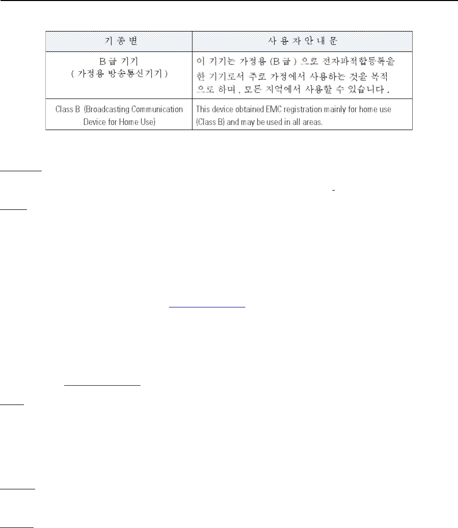
5.9.3 Korea Warning Statement for Class B
5.9.4 Other Countries
Australia
Use of 5GHz RLAN’s in Australia is restricted in the following band 5.50 – 5.65GHz.
Brazil
Regulatory declarations for AP7131N - BRAZIL
Note: The certification mark applied to the AP7131N is for Restrict Radiation Equipment. This equipment operates
on a secondary basis and does not have the right for protection against harmful interference from other users
including same equipment types. Also this equipment must not cause interference to systems operating on primary
basis.
For more information consult the website www.anatel.gov.br
Declarações Regulamentares para AP7131N - Brasil
Nota: A marca de certificação se aplica ao Transceptor, modelo AP7131N. Este equipamento opera em caráter
secundário, isto é, não tem direito a proteção contra interferência prejudicial, mesmo de estações do mesmo tipo,
e não pode causar interferência a sistemas operando em caráter primário. Para maiores informações sobre ANATEL
consulte o site: www.anatel.gov.br
Chile
Este equipo cumple con la Resolución No 403 de 2008, de la Subsecretaria de telecomunicaciones, relativa a
radiaciones electromagnéticas.
This device complies with the Resolution Not 403 of 2008, of the Undersecretary of telecommunications, relating
to electromagnetic radiation.
Mexico
Restrict Frequency Range to: 2.450 – 2.4835 GHz.
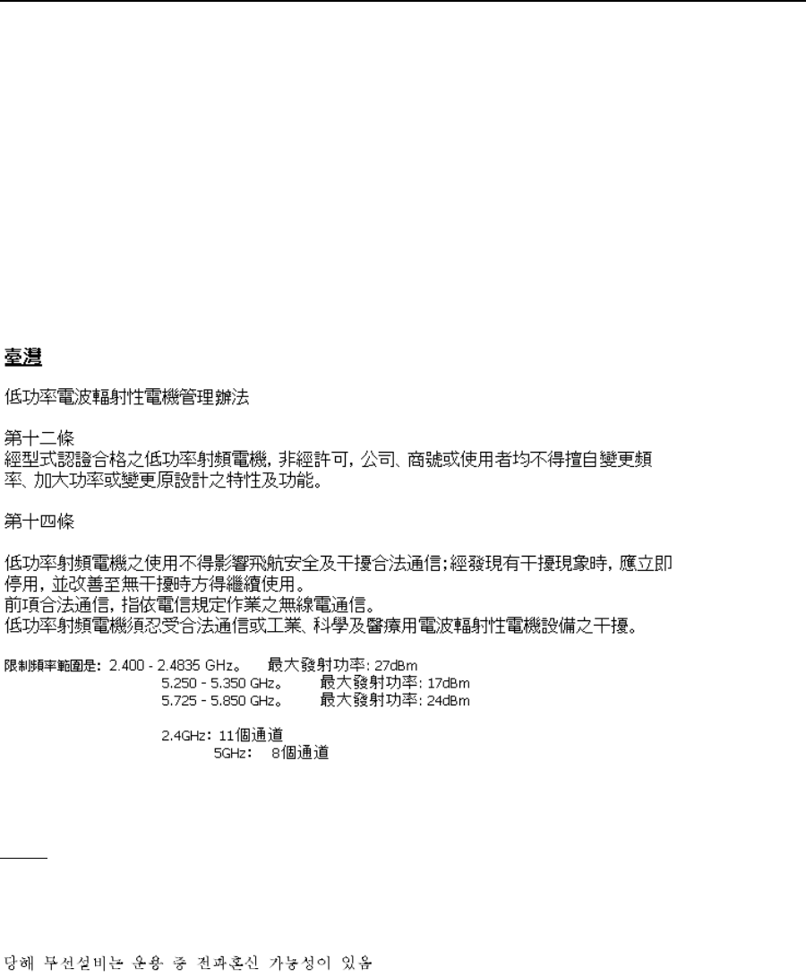
Taiwan
NOTICE!
According to: Administrative Regulations on Low Power Radio Waves Radiated Devices
Installation Guide 43
Article 12
Without permission granted by the DGT, any company, enterprise, or user is not allowed to change frequency,
enhance transmitting power or alter original characteristic as well as performance to a approved low power
radio-frequency devices.
Article 14
The low power radio-frequency devices shall not influence aircraft security and interfere legal communications; If
found, the user shall cease operating immediately until no interference is achieved. The said legal communications
means radio communications is operated in compliance with the Telecommunications Act. The low power
radio-frequency devices must be susceptible with the interference from legal communications or ISM radio wave
radiated devices.
Wireless device operate in the frequency band of 5.25-5.35 GHz, limited for Indoor use only.
在5.25-5.35 秭赫頻帶內操作之無線資訊傳輸設備,限於室內使用
Korea
For a radio equipment using 2400~2483.5MHz or 5725~5825MHz, the following two expressions should be
displayed:
1. This radio equipment can be interfered during operation.

44 AP-7131 Access Point
2. This radio equipment cannot provide a service relevant to the human life safety.

Installation Guide 45
5.10 Waste Electrical and Electronic Equipment (WEEE)
English: For EU Customers: All products at the end of their life must be
returned to Motorola for recycling. For information on how to return product,
please go to: http://www.motorola.com/recycling/weee.
Français: Clients de l'Union Européenne: Tous les produits en fin de cycle
de vie doivent être retournés à Motorola pour recyclage. Pour de plus amples
informations sur le retour de produits, consultez :
http://www.motorola.com/recycling/weee.
Español: Para clientes en la Unión Europea: todos los productos deberán
entregarse a Motorola al final de su ciclo de vida para que sean reciclados.
Si desea más información sobre cómo devolver un producto, visite:
http://www.motorola.com/recycling/weee.
Bulgarish: За клиенти от ЕС: След края на полезния им живот всички
продукти трябва да се връщат на Motorola за рециклиране. За информация
относно връщането на продукти, моля отидете на адрес:
http://www.motorola.com/recycling/weee.
Deutsch: Für Kunden innerhalb der EU: Alle Produkte müssen am Ende
ihrer Lebensdauer zum Recycling an Motorola zurückgesandt werden.
Informationen zur Rücksendung von Produkten finden Sie unter
http://www.motorola.com/recycling/weee.
Italiano: per i clienti dell'UE: tutti i prodotti che sono giunti al termine del
rispettivo ciclo di vita devono essere restituiti a Motorola al fine di consentirne
il riciclaggio. Per informazioni sulle modalità di restituzione, visitare il
seguente sito Web: http://www.motorola.com/recycling/weee.
Português: Para clientes da UE: todos os produtos no fim de vida devem
ser devolvidos à Motorola para reciclagem. Para obter informações sobre
como devolver o produto, visite: http://www.motorola.com/recycling/weee.
Nederlands: Voor klanten in de EU: alle producten dienen aan het einde van
hun levensduur naar Motorola te worden teruggezonden voor recycling.
Raadpleeg http://www.motorola.com/recycling/weee voor meer informatie
over het terugzenden van producten.
Polski: Klienci z obszaru Unii Europejskiej: Produkty wycofane z eksploatacji
nale¿y zwróciæ do firmy Motorola w celu ich utylizacji. Informacje na temat
zwrotu produktów znajduj¹ siê na stronie internetowej
http://www.motorola.com/recycling/weee.
Čeština: Pro zákazníky z EU: Všechny produkty je nutné po skonèení jejich
životnosti vrátit spoleènosti Motorola k recyklaci. Informace o zpùsobu
vrácení produktu najdete na webové stránce:
http://www.motorola.com/recycling/weee.
Eesti: EL klientidele: kõik tooted tuleb nende eluea lõppedes tagastada
taaskasutamise eesmärgil Motorola'ile. Lisainformatsiooni saamiseks toote
tagastamise kohta külastage palun aadressi:
http://www.motorola.com/recycling/weee.
Magyar: Az EU-ban vásárlóknak: Minden tönkrement terméket a Motorola
vállalathoz kell eljuttatni újrahasznosítás céljából. A termék
visszajuttatásának módjával kapcsolatos tudnivalókért látogasson el a
http://www.motorola.com/recycling/weee weboldalra.

46 AP-7131 Access Point
5.11 TURKISH WEEE Statement of Compliance
EEE Yönetmeliğine Uygundur
Svenska: För kunder inom EU: Alla produkter som uppnått sin livslängd
måste returneras till Motorola för återvinning. Information om hur du
returnerar produkten finns på http://www.motorola.com/recycling/weee.
Suomi: Asiakkaat Euroopan unionin alueella: Kaikki tuotteet on palautettava
kierrätettäväksi Motorola-yhtiöön, kun tuotetta ei enää käytetä. Lisätietoja
tuotteen palauttamisesta on osoitteessa
http://www.motorola.com/recycling/weee.
Dansk: Til kunder i EU: Alle produkter skal returneres til Motorola til
recirkulering, når de er udtjent. Læs oplysningerne om returnering af
produkter på: http://www.motorola.com/recycling/weee.
Ελληνικά: Για πελάτες στην Ε.Ε.: Όλα τα προϊόντα, στο τέλος της διάρκειας
ζωής τους, πρέπει να επιστρέφονται στην Motorola για ανακύκλωση. Για
περισσότερες πληροφορίες σχετικά με την επιστροφή ενός προϊόντος,
επισκεφθείτε τη διεύθυνση http://www.motorola.com/recycling/weee στο
∆ιαδίκτυο.
Malti: Għal klijenti fl-UE: il-prodotti kollha li jkunu waslu fl-aħħar tal-ħajja ta'
l-użu tagħhom, iridu jiġu rritornati għand Motorola għar-riċiklaġġ. Għal aktar
tagħrif dwar kif għandek tirritorna l-prodott, jekk jogħġbok żur:
http://www.motorola.com/recycling/weee.
Românesc: Pentru clienţii din UE: Toate produsele, la sfârşitul duratei lor de
funcţionare, trebuie returnate la Motorola pentru reciclare. Pentru informaţii
despre returnarea produsului, accesaţi:
http://www.motorola.com/recycling/weee.
Slovenski: Za kupce v EU: vsi izdelki se morajo po poteku življenjske dobe
vrniti podjetju Motorola za reciklažo. Za informacije o vračilu izdelka obiščite:
http://www.motorola.com/recycling/weee.
Slovenčina: Pre zákazníkov z krajín EU: Všetky výrobky musia byť po
uplynutí doby ich životnosti vrátené spoločnosti Motorola na recykláciu.
Bližšie informácie o vrátení výrobkov nájdete na:
http://www.motorola.com/recycling/weee.
Lietuvių: ES vartotojams: visi gaminiai, pasibaigus jų eksploatacijos laikui,
turi būti grąžinti utilizuoti į kompaniją „Motorola“. Daugiau informacijos, kaip
grąžinti gaminį, rasite: http://www.motorola.com/recycling/weee.
Latviešu: ES klientiem: visi produkti pēc to kalpošanas mūža beigām ir
jānogādā atpakaļ Motorola otrreizējai pārstrādei. Lai iegūtu informāciju par
produktu nogādāšanu Motorola, lūdzu, skatiet:
http://www.motorola.com/recycling/weee.
Türkçe: AB Müşterileri için: Kullanım süresi dolan tüm ürünler geri
dönüştürme için Motorola'ya iade edilmelidir. Ürünlerin nasıl iade edileceği
hakkında bilgi için lütfen şu adresi ziyaret edin:
http://www.motorola.com/recycling/weee.

Installation Guide 47
6 Motorola Solutions Support Center
If you have a problem with your equipment, contact support for your region.
Contact information is available at: http://www.motorolasolutions.com/support.
When contacting Motorola Solutions support, please provide the following information:
• Serial number of the unit
• Model number or product name
• Software type and version number
Motorola Solutions responds to calls by e-mail, telephone, or fax within the time limits set forth in support
agreements. If you purchased your product from a Motorola Solutions business partner, contact that business
partner for support.
Customer Support Web Sites
The Motorola Solutions Support Central Web site, located at http://supportcentral.motorolasolutions.com/
provides information and online assistance including developer tools, software downloads, product manuals and
online repair requests.
Manuals
http://supportcentral.motorolasolutions.com/support/produt/manuals.do
General Information
Obtain additional information by contacting Motorola Solutions at:
Telephone (North America): 1-800-722-6234
Telephone (International): +1-631-738-5200
Website: http://www.motorolasolutions.com

48 AP-7131 Access Point
7 AP7131 Series ROHS Compliance
O:表示该有毒有害物质在该部件所有均质材料中的含量均在 SJ/T11363-2006 标准规定的限量要求以下。
X:表示该有毒有害物质至少在该部件的某一均质材料中的含量超出 SJ/T11363-2006 标准规定的限量要求。
对销售之日的所售产品,本表表示,公司供应链的电子信息产品可能包含这些物质。注意:在所售产品中可能会也
可能不会含有所有所列的部件。
This table was created to comply with China RoHS requirements for Motorola Solution’s AP7131 and AP7131N
model Access Points.
有毒有害物质或元素
部件名称
(Parts)
铅
(Pb)
汞
(Hg)
镉
(Cd)
六价铬
(Cr6+)
多溴联苯
(PBB)
多溴二苯醚
(PBDE)
金属部件
(Metal Parts)
XOOOO O
电路模块
(Circuit Modules)
XOOOO O
电缆及电缆组件
(Cables and Cable Assemblies)
XOOOO O
塑料和聚合物部件
(Plastic and Polymeric Parts)
OOOOO O
光学和光学组件
(Optics and Optical Components)
OOOOO O
电池
(Batteries)
OOOOO O

Installation Guide 49

50 AP-7131 Access Point

Installation Guide 51

Motorola Solutions, Inc.
1301 E. Algonquin Rd.
Schaumburg, IL 60196-1078, U.S.A.
http://www.motorolasolutions.com
MOTOROLA, MOTO, MOTOROLA SOLUTIONS and the Stylized M Logo are trademarks or registered trademarks of Motorola
Trademark Holdings, LLC and are used under license. All other trademarks are the property of their respective owners.
© 2013 Motorola Solutions, Inc. All Rights Reserved.
MN000037A01
Revision A June 2013