Zebra Technologies AP7522 Oak External User Manual AP 7522 Access Point Installation Guide
Zebra Technologies Corporation Oak External AP 7522 Access Point Installation Guide
UserManual.wiki
>
Zebra Technologies
>
AP7522 User Manual
>
Users Manual
Contents
1.
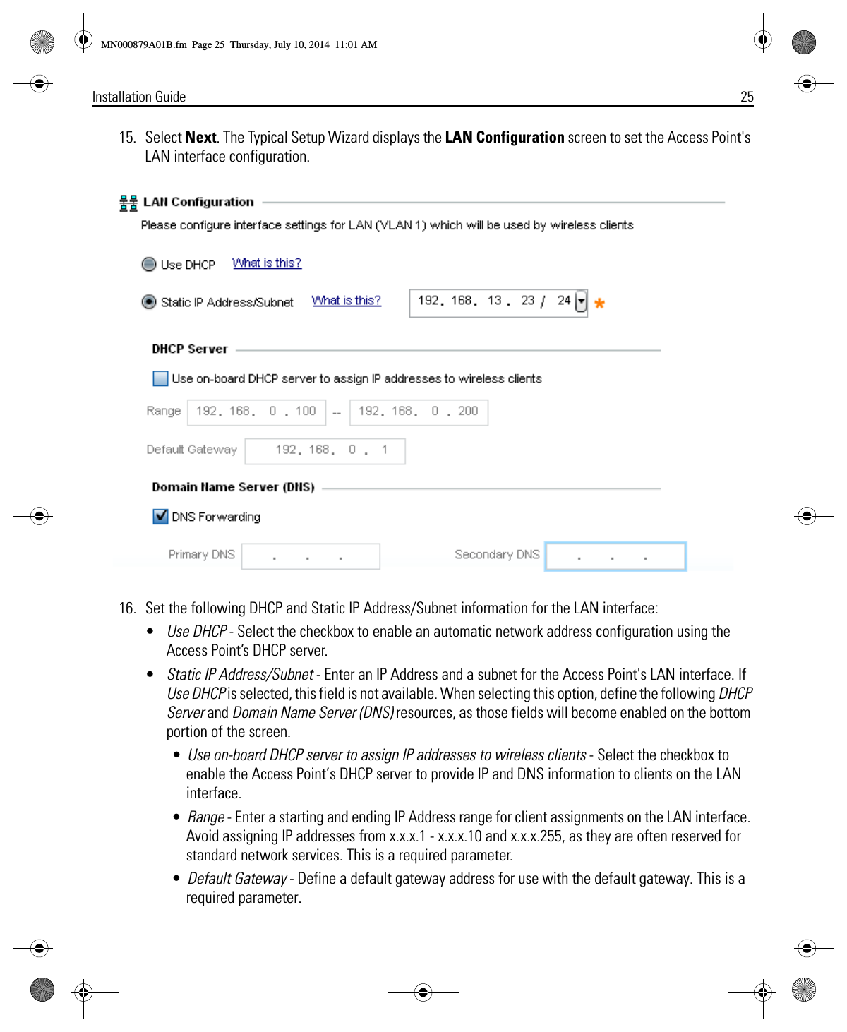
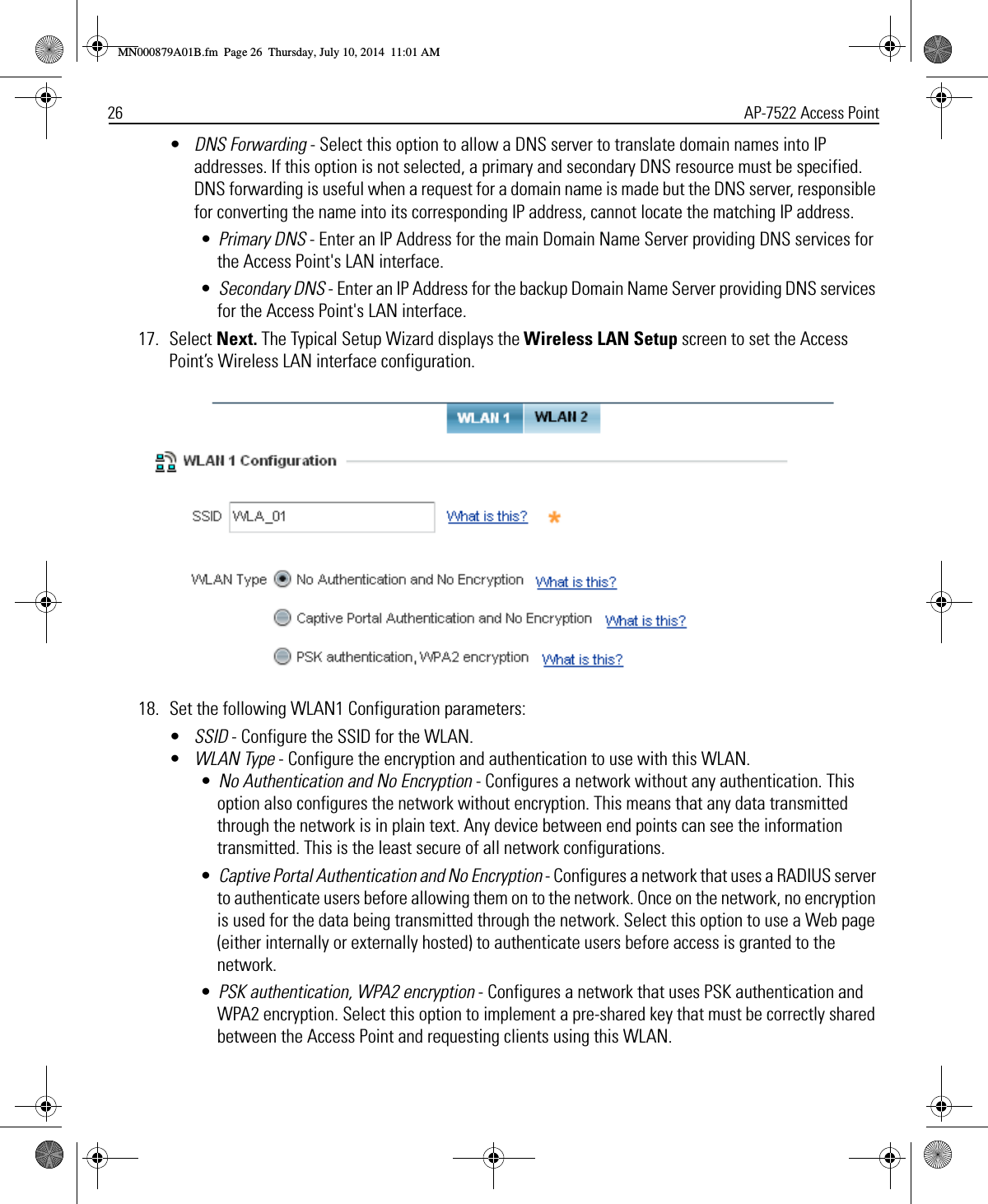
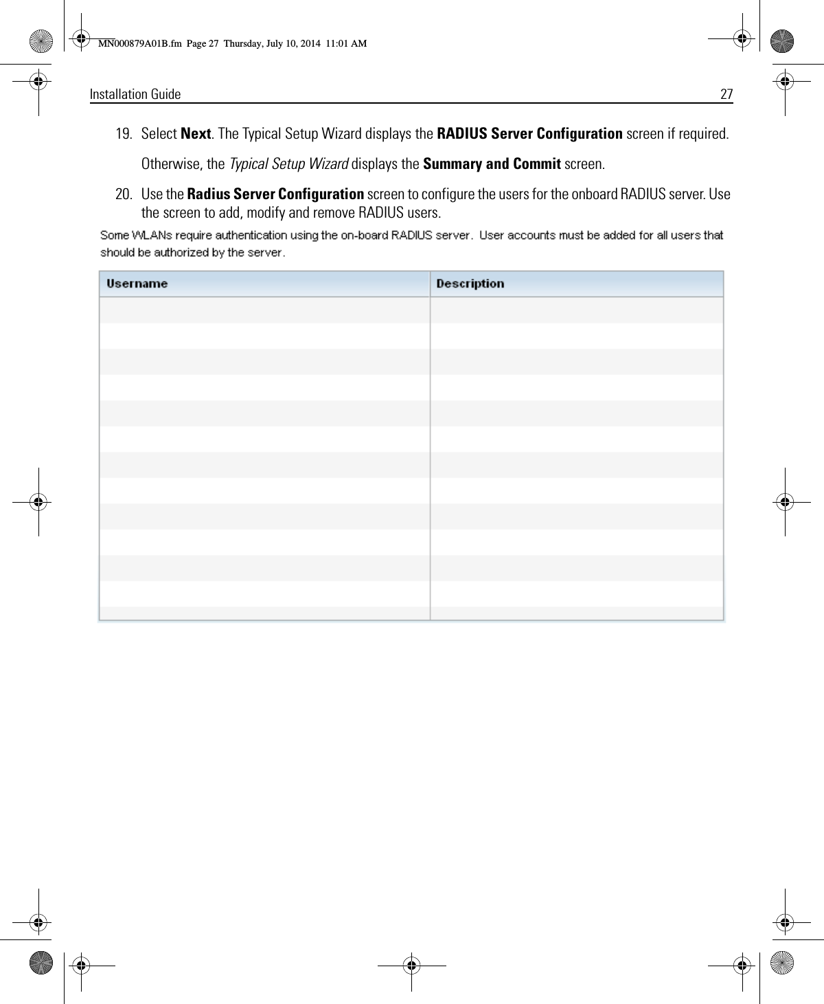
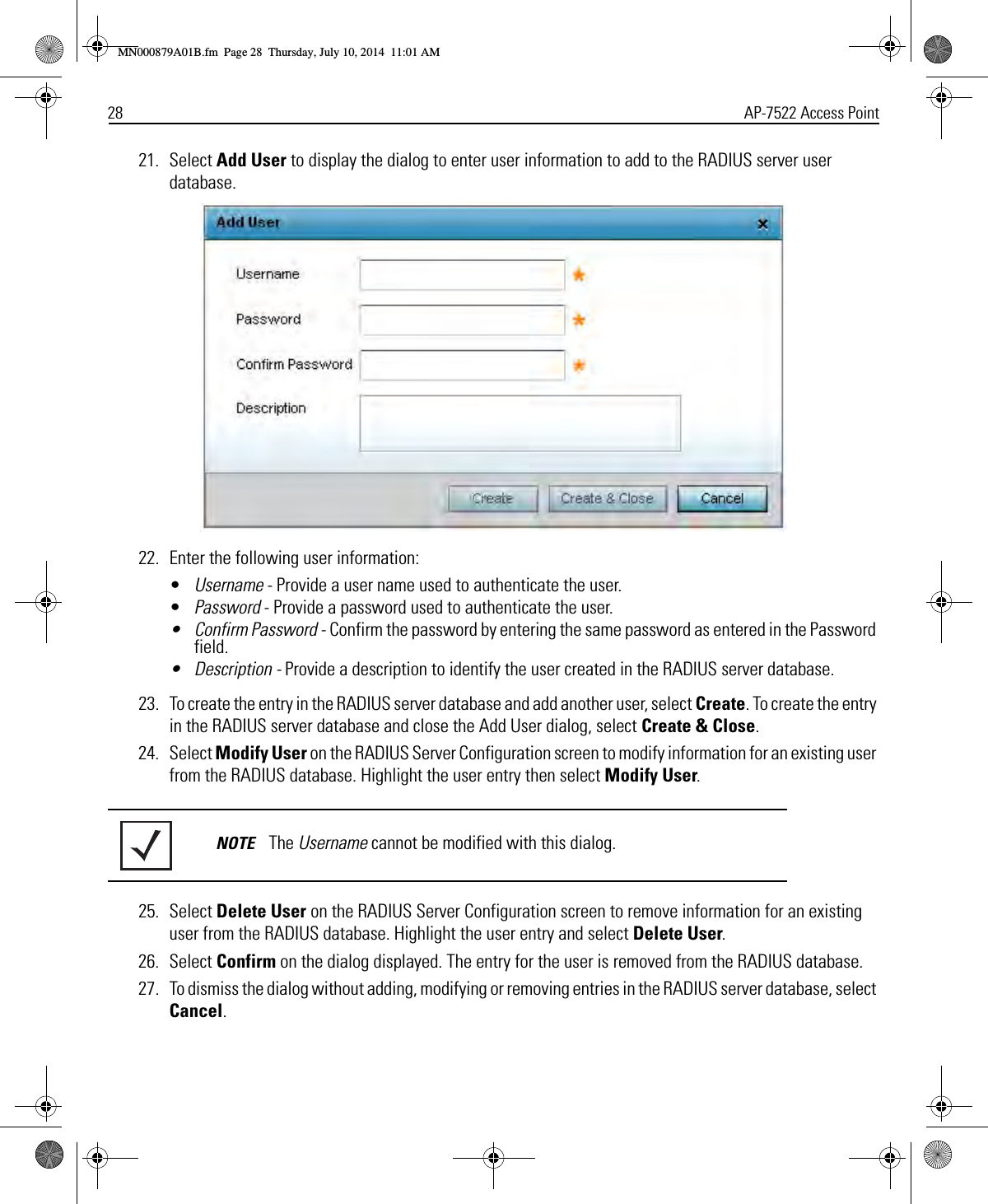
Users Manual
2.
User Manual
Users Manual
Navigation menu
Upload a User Manual
Namespaces
Wiki Guide
HTML
PDF
Info
Views
User Manual
Discussion / Help
Navigation