Zebra Technologies ECHO108 Echo Distance Measuring Radio User Manual Echo DMR users guide Final
Zebra Technologies Corporation Echo Distance Measuring Radio Echo DMR users guide Final
User Manual

Echo Distance Measurement Radio User’s Guide
ISSUE 2.00
MULTISPECTRAL SOLUTIONS, INC.
1 of 10
Echo Distance Measurement Radio
User’s Guide

Echo Distance Measurement Radio User’s Guide
ISSUE 2.00
MULTISPECTRAL SOLUTIONS, INC.
2 of 10
NOTE: The Echo Distance Measurement Radio (DMR) unit has been tested to comply
with FCC Part 15, Subpart C for wideband pulse emitter devices. Changes or
modifications to the radiating elements of Echo DMR not expressly approved by the
party responsible for compliance could void the user’s authority to operate the
equipment.
NOTE: The Echo DMR is certified under the FCC Part 15.250 rule which restricts
certain applications and use. Operation on board an aircraft or a satellite is prohibited.
The Echo DMR may not be employed for the operation of toys. The use of Echo DMR
on a fixed outdoor infrastructure is prohibited. A fixed infrastructure includes antennas
mounted on outdoor structures, e.g., antennas mounted on the outside of a building or
on a telephone pole.
NOTE: The Echo DMR is approved as a modular transmitter under FCC Part 15.212.
Therefore any equipment that installs the module must include an external label stating
that unit “Contains FCC ID: QCJECHO108”.
NOTE: The Echo DMR unit has been tested and found to comply with the limits for a
Class B digital device, pursuant to Part 15 of the FCC Rules. These limits are designed
to provide reasonable protection against harmful interference in a residential installation.
This equipment generates, uses and can radiate radio frequency energy and, if not
installed and used in accordance with the instructions, may cause harmful interference
to radio communications. However, there is no guarantee that interference will not occur
in a particular installation. If this equipment does cause harmful interference to radio or
television reception, which can be determined by turning the equipment off and on, the
user is encouraged to try to correct the interference by one or more of the following
measures:
—Reorient or relocate the receiving antenna.
—Increase the separation between the equipment and receiver.
—Connect the equipment into an outlet on a circuit different from that to which the
receiver is connected.
—Consult the dealer or an experienced radio/TV technician for help.

Echo Distance Measurement Radio User’s Guide
ISSUE 2.00
MULTISPECTRAL SOLUTIONS, INC. PROPRIETARY AND CONFIDENTIAL
3 of 10
CONTENTS
1 INTRODUCTION ......................................................................................6
2 HARDWARE CONNECTIONS..................................................................7
2.1 ANTENNA JACK............................................................................8
2.2 POWER CONNECTOR..................................................................8
2.3 RS232 CONNECTOR ....................................................................9
2.4 USB CONNECTOR........................................................................9
2.5 BAUD RATE...................... ERROR! BOOKMARK NOT DEFINED.
3 RS232 INTERFACE................................................................................10
3.1 CONFIGURATION .......................................................................10
3.2 SERIAL PORT COMMUNICATION PROTOCOL...............ERROR!
BOOKMARK NOT DEFINED.
3.2.1 GENERAL NOTES. ERROR! BOOKMARK NOT DEFINED.

Echo Distance Measurement Radio User’s Guide
ISSUE 2.00
MULTISPECTRAL SOLUTIONS, INC. PROPRIETARY AND CONFIDENTIAL
4 of 10
LIST OF FIGURES
FIGURE 1: ECHO DMR MODULE CONNECTIONS PART 1..............................7
FIGURE 2: ECHO MDR MODULE CONNECTIONS PART 2..............................8

Echo Distance Measurement Radio User’s Guide
ISSUE 2.00
MULTISPECTRAL SOLUTIONS, INC. PROPRIETARY AND CONFIDENTIAL
5 of 10
LIST OF TABLES
TABLE 1: POWER CONNECTOR PINOUTS ...........ERROR! BOOKMARK NOT
DEFINED.
TABLE 2: RS232 CONNECTOR PINOUTS..............ERROR! BOOKMARK NOT
DEFINED.
TABLE 3: BAUD RATE SUMMARY ........ERROR! BOOKMARK NOT DEFINED.

Echo Distance Measurement Radio User’s Guide
ISSUE 2.00
MULTISPECTRAL SOLUTIONS, INC. PROPRIETARY AND CONFIDENTIAL
6 of 10
1 INTRODUCTION
The Multispectral Solutions, Inc. Echo Distance Measurement Radio (DMR) is
designed to range between multiple Echo DMR units using Wideband short pulse
technology. A minimum of two Echo units are required for each system.
Echo Distance Measurement Radio User’s Guide
ISSUE 2.00
MULTISPECTRAL SOLUTIONS, INC. PROPRIETARY AND CONFIDENTIAL
7 of 10
2 HARDWARE CONNECTIONS
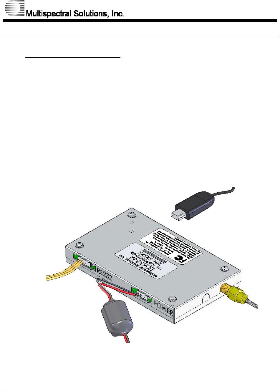
Each Echo radio module has the following external connections:
• Antenna Jack – Reverse polarity SMA jack
• Power Connector – Input voltage range is 3-5 Vdc.
• RS232 Connector – Baud rate of 115200 bps
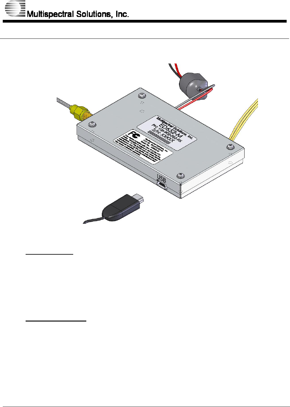
• USB Connector – Baud rate of 921600 bps. Powers unit over USB in
addition to communication.
Figure 1: Echo DMR Module Connections Part 1
Echo Distance Measurement Radio User’s Guide
ISSUE 2.00
MULTISPECTRAL SOLUTIONS, INC. PROPRIETARY AND CONFIDENTIAL
8 of 10
Figure 2: Echo MDR Module Connections Part 2
2.1 Antenna Jack
The antenna jack on the Echo DMR module is an SMA reverse polarity jack. The
antenna jack on the antenna itself is an SMA reverse polarity jack as well.
The Echo radio module is FCC approved for only the supplied antenna and
cable.
2.2 Power Connector
The mating connector housing is Molex 51021-0600 and the pins are Molex
50079-8000. The LED output listed in the table is used to indicate that power is
applied to the unit. The power connector supplied with the module includes a
ferrite choke so that the unit will meet unintended emission specifications of Part
15 subpart B regulations. The unit must use the provided power cable connector
assembly to be FCC compliant under Part 15 subpart B if powered through this
connection.

Echo Distance Measurement Radio User’s Guide
ISSUE 2.00
MULTISPECTRAL SOLUTIONS, INC. PROPRIETARY AND CONFIDENTIAL
9 of 10
2.3 RS232 Connector
The mating connector housing is Molex 51021-0700 and the pins are Molex
50079-8000. The DB9 connections are listed for reference to connect the Echo
unit to the serial port of a computer.
2.4 USB Connector
The USB jack on the Echo DMR module is a mini USB 5-pin type B jack. The
Echo unit is fully powered when using the USB.

Echo Distance Measurement Radio User’s Guide
ISSUE 2.00
MULTISPECTRAL SOLUTIONS, INC. PROPRIETARY AND CONFIDENTIAL
10 of 10
3 RS232 INTERFACE
Each Echo DMR is capable of communicating with external equipment via a
serial connection. The external equipment is the master and the Echo DMR is
the slave. In other words, the Echo radio unit will not send anything over the
serial connection unless it is responding to a command received from the
external equipment with the exception of at power-up.
3.1 Configuration
115200 bps, 8 data bits, 1 start bit, 1 stop bit, no parity, no flow control for RS232
port
921600 bps, 8 data bits, 1 start bit, 1 stop bit, no parity, no flow control for USB
port