Zebra Technologies LOS5000 LOS-5000 User Manual Users Guide
Zebra Technologies Corporation LOS-5000 Users Guide
UserManual.wiki
>
Zebra Technologies
>
LOS5000 User Manual
>
Users Guide
Contents
1.
Users Manual
2.
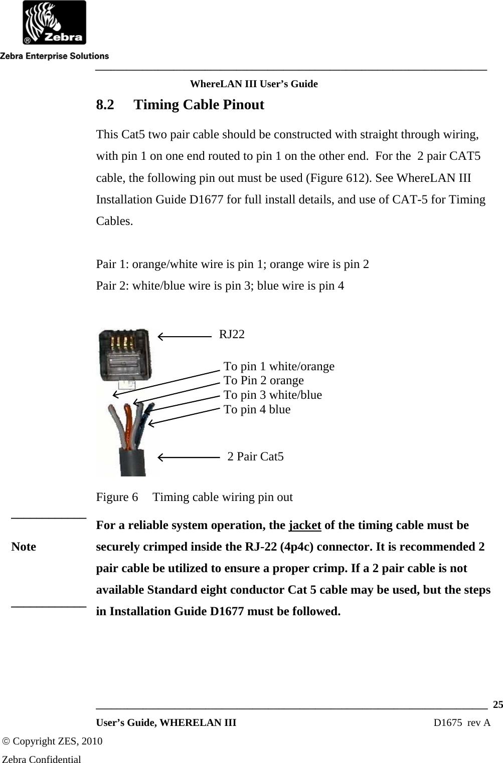
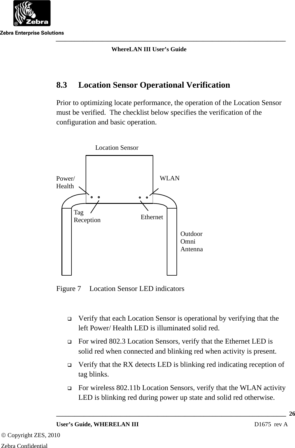
Users Guide
Users Guide
Navigation menu
Upload a User Manual
Namespaces
Wiki Guide
HTML
PDF
Info
Views
User Manual
Discussion / Help
Navigation