Zebra Technologies LOS5000B Real Time Location Sensor User Manual Manual DRAFT
Zebra Technologies Corporation Real Time Location Sensor Manual DRAFT
Manual DRAFT

___________________________________________________________________________
WhereLAN III User’s Guide
___________________________________________________________________________ 1
User’s Guide, WhereLAN III draft D1675 rev F
© Copyright Zebra Technologies, 2012
Zebra Confidential
WhereLAN III
LOS-5000
User’s Guide
DRAFT

___________________________________________________________________________
WhereLAN III User’s Guide
___________________________________________________________________________ 2
User’s Guide, WhereLAN III draft D1675 rev F
© Copyright Zebra Technologies, 2012
Zebra Confidential
Typographical Conventions
Warnings call attention to a procedure or practice that could result in
personal injury if not correctly performed. Do not proceed until you fully
understand and meet the required conditions.
Cautions call attention to an operation procedure or practice that could
damage the product, or degrade performance if not correctly performed.
Do not proceed until understanding and meeting these required
conditions.
Notes provide information that can be helpful in understanding the
operation of the product.
_____________
_____________
____________
Note
____________
____________
____________

___________________________________________________________________________
WhereLAN III User’s Guide
___________________________________________________________________________ 3
User’s Guide, WhereLAN III draft D1675 rev F
© Copyright Zebra Technologies, 2012
Zebra Confidential
Document Revision History
Revision Description of Changes Date Approved
A Initial Release 10/20/10 GLC
B Per ECO C02532 05/09/11 GLC
C Addition of Secure Shell, Wi-Fi
configuration, Network Auto-
configuration (DHCP), and general
errata.
8/28/11
SR
D Per ECO C02834 04/04/12 GC
E Per ECO C02879 05/21/12 GC

___________________________________________________________________________
WhereLAN III User’s Guide
___________________________________________________________________________ 4
User’s Guide, WhereLAN III draft D1675 rev F
© Copyright Zebra Technologies, 2012
Zebra Confidential
Table of Contents Page
TABLE OF FIGURES .................................................................................................................. 5
1DOCUMENT OVERVIEW ................................................................................................. 8
2PRODUCT DESCRIPTION AND FEATURES ................................................................ 8
3PRODUCT SPECIFICATIONS ........................................................................................ 11
3.1MECHANICAL ................................................................................................................. 11
3.2ELECTRICAL ................................................................................................................... 11
3.3ENVIRONMENTAL ........................................................................................................... 11
3.4EXTERNAL CONNECTIONS .............................................................................................. 12
4ACCESSORIES .................................................................................................................. 13
5CONFIGURATION & CONTROL .................................................................................. 14
5.1WHERELAN III SELF BOOT ........................................................................................... 14
5.2WHERELAN III INTERFACE ........................................................................................... 16
5.3WHERELAN III MAC/ IP ADDRESS CONFIGURATION ................................................... 23
5.4WI-FI CLIENT CONFIGURATION (LOS-5000-00AB ONLY) ............................................ 39
5.5WPA SUPPLICANT UPLOAD ........................................................................................... 44
6INSTALLATION AND MOUNTING .............................................................................. 50
6.1SAFETY AND INSTALLATION WARNINGS AND CAUTIONS ............................................... 50
6.2MOUNTING ..................................................................................................................... 51
6.33/8THS THREADED ROD ................................................................................................. 53
6.4POLE MOUNT KIT .......................................................................................................... 55
7ANTENNAS......................................................................................................................... 61
7.2VERTICAL DIVERSITY MOUNTING ................................................................................. 65
7.3WI-FI 802.11 B/G ANTENNAS......................................................................................... 68
8CABLING ............................................................................................................................ 69
8.1POWER, AC ................................................................................................................... 70
8.1ETHERNET ...................................................................................................................... 71
8.2WI-FI ANTENNA KIT ...................................................................................................... 71
8.3TIMING CABLE INTERCONNECTION GUIDELINES ............................................................ 77
8.4LOCATION SENSOR OPERATIONAL VERIFICATION ......................................................... 84
REGULATORY INFORMATION ........................................................................................... 86
APPENDIX A: LOS-5000 EFFECTIVE PROJECTED AREA (EPA) ................................. 89

___________________________________________________________________________
WhereLAN III User’s Guide
___________________________________________________________________________ 5
User’s Guide, WhereLAN III draft D1675 rev F
© Copyright Zebra Technologies, 2012
Zebra Confidential
APPENDIX B: LOS-5000 WEIGHT ....................................................................................... 90
APPENDIX C: WI-FI REGULATORY COMPLIANCE ..................................................... 91
APPENDIX D: FIRMWARE UPGRADE ............................................................................... 93
APPENDIX E: HYPERTERMINAL BOOT SEQUENCE ................................................... 98
Table of Figures
Figure 1 LOS-5000 LED's ............................................................................................................ 14
Figure 2Example of LOS-5000-00AB Label ......................................................................... 36
Figure 3 Safety and Warnings ....................................................................................................... 50

___________________________________________________________________________
WhereLAN III User’s Guide
___________________________________________________________________________ 6
User’s Guide, WhereLAN III draft D1675 rev F
© Copyright Zebra Technologies, 2012
Zebra Confidential
Figure 4 Mounting Points ............................................................................................................. 51
Figure 5 Safety Lanyard................................................................................................................ 52
Figure 6 Threaded-Rod ................................................................................................................. 53
Figure 7 Safety Lanyard................................................................................................................ 54
Figure 8 Pole Mount Kit ............................................................................................................... 55
Figure 9 Bracket Mount ................................................................................................................ 56
Figure 10 Retaining Bolts ............................................................................................................. 57
Figure 11 Location Sensor Mounted ............................................................................................. 58
Figure 12 Pole mount on Pole ....................................................................................................... 59
Figure 13 Location Sensor on Pole ............................................................................................... 60
Figure 14 Office Omni .................................................................................................................. 61
Figure 15 All Weather Omni ........................................................................................................ 61
Figure 16Minimum clearance to metallic structures ................................................................ 62
Figure 17Corner mount industrial application ......................................................................... 63
Figure 18Office omnidirectional in corridor ............................................................................ 64
Figure 19 Vertical Diversity 5ft, ................................................................................................... 66
Figure 20 Vertical Diversity +11ft. ............................................................................................... 67
Figure 21 Vertical Diversity Connections .................................................................................... 68
Figure 22 Location Sensor Connections ....................................................................................... 69
Figure 23 Drip Plug ...................................................................................................................... 69
Figure 24 CBK-020-00 ................................................................................................................. 71
Figure 25 Wi-Fi Cable 1 ............................................................................................................... 72
Figure 26 Wi-Fi Cables Drip Plug ................................................................................................ 73
Figure 27 Wi-Fi Bracket ............................................................................................................... 74
Figure 28 2.2 dBi Dipole .............................................................................................................. 75
Figure 29 2.2 dBi Installed............................................................................................................ 75
Figure 30 Wi-Fi Bracket Remote Antenna ................................................................................... 76
Figure 31 Remote Antenna Clamp ............................................................................................... 76
Figure 32Timing cable wiring pin out ...................................................................................... 78
Figure 33 Timing Cable Trim ....................................................................................................... 79
Figure 34 Timing Cable Jacket ..................................................................................................... 79
Figure 35 Timing Cable Trim ....................................................................................................... 80
Figure 36 Timing Cable Pull Jacket.............................................................................................. 80
Figure 37 Timing Cable Crimp ..................................................................................................... 81
Figure 38Test setup for CAT5 cable using Fluke 620 ............................................................. 82
Figure 39Correct readout when testing 2 pair cable. ................................................................ 83
Figure 40Location Sensor LED indicators ............................................................................... 84
Figure 41 Ftproot Directory .......................................................................................................... 93

___________________________________________________________________________
WhereLAN III User’s Guide
___________________________________________________________________________ 7
User’s Guide, WhereLAN III draft D1675 rev F
© Copyright Zebra Technologies, 2012
Zebra Confidential
Figure 42 VSS Firmware 4.0.5.2 Directory .................................................................................. 94

___________________________________________________________________________
WhereLAN III User’s Guide
___________________________________________________________________________ 8
User’s Guide, WhereLAN III draft D1675 rev F
© Copyright Zebra Technologies, 2012
Zebra Confidential
1 DOCUMENT OVERVIEW
This document describes the basic configuration and recommendations on
physical installation of the WhereLAN III product, which is part of the
Location Sensor product line. The site design and placement is detailed in the
Location Sensor Placement Guide D0406 and WhereLAN III Instruction
Sheet (26913), provide with each unit.
2 PRODUCT DESCRIPTION AND FEATURES
The WhereLAN III is the next generation of WhereLAN product that receives
the signals transmitted by WhereTags (ISO 24730-2), and provides data to the
Location Algorithm processor. The received tag blinks are decoded, time
stamped, and routed to a Windows Server or ZLA (Zebra Location Appliance)
for additional processing. The locate algorithm running on the Windows
Server or ZLA calculates the tag position based on the time stamps of multiple
Location Sensors, and reports that position to the database where it is
displayed by Resource Manager.
The WhereLAN III Location Sensor supports the same Real Time Locating
System (RTLS) functions as the previous sensor, known as the WhereLAN
Location Sensor (LOS). WhereLAN III is fully backwards compatible and
may be used, as outlined herein, as a drop-in replacement for any existing
LOS. However, the WhereLAN III incorporates modern and patent-pending
techniques that result in superior accuracy performance over the current LOS
product. In addition, WhereLAN III supports a number of other value-added
features, as follows:
Time Synchronization: Like the LOS, WhereLAN III supports wireless and
wired time synchronization. However, the product can operate in two distinct
time synchronization modes, known as “Legacy” and “Time Synch II” As
shipped, the product defaults to Legacy time synchronization. In Legacy
mode, WhereLAN III is drop-in compatible with LOS and is backwards
compatible with VSS release 3.8. The Legacy Time service relies on various
user-defined entities, such as Line-of-Sight lists and Timing Islands. Time
Synch II no longer exposes these entities to the end user. A site must run
either the Legacy Time service or the Time Synch II service, but not both. In
Time Synch II mode, WhereLAN III furnishes additional data required by a
new Time Synchronization Process, scheduled for release in Q4 2012, which
runs on the Windows Server or ZLA. The Time Synch II service reduces site
design complexity and post-install support. It accomplishes this by being
“self-configuring” and “self-adjusting”; it hides its configuration details from

___________________________________________________________________________
WhereLAN III User’s Guide
___________________________________________________________________________ 9
User’s Guide, WhereLAN III draft D1675 rev F
© Copyright Zebra Technologies, 2012
Zebra Confidential
the end user, automatically self configures and automatically adjusts to a wide
range of Radio Frequency environmental changes. The new Time Synch II
service is substantially different from and is not backwards compatible with
the Legacy Time Synch service. In Legacy mode, the embedded wireless time
beacons are transmitted over the right channel whereas both the left and right
channels are used in Time Synch II mode. Time Synch II can operate in an all
WhereLAN IIIs network, an all LOSs network, or a network with mixed
WhereLAN IIIs and LOSs. However, in order for Time Synch II to work with
LOSs, they must operate in “dual-posting” mode.
Wi-Fi: A variant of the LOS, known as a Locating Access Point (LAP),
supports an integral 802.11 b/g/a Access Point. WhereLAN III does not
support an integral Access Point. Instead, a variant of WhereLAN III supports
establishing an 802.11 b/g Wi-Fi client side connection to any industry-
standard Access Point. Unlike WhereLAN III, the LOS does not support
establishing Wi-Fi client side connections.
Network Auto-Configuration (DHCP) and IPv6: The WhereLAN III, with the
release of VSS 4.0.5.2 support both DHCP IP and IPv6 address assignment.
However, the methods used by system software to establish connectivity with
the sensors on start-up preclude the full use of (dynamic) DHCP IP addresses.
This restriction is being eliminated, in the VSS 4.0.5.2 release, for WhereLAN
III sensors by a new process, referred to as Network AutoConfig. This
process conveys the IP address of the RTLS server to the WhereLAN IIIs as
part of the standard DHCP IP address assignment message exchange. In turn,
the WhereLAN IIIs “check-in” with the RTLS server by passing it the MAC
address of their Ethernet port. The RTLS server uses the MAC address to
“authenticate” the identity of the WhereLAN IIIs by checking for the MAC
addresses to be present in the site configuration file.
IEEE 802.3af Power of Ethernet (PoE): WhereLAN III supports industry-
standard PoE. This allows for easier installation as it removes the need to run
DC power cabling to the unit. PoE may be supplied by any standards-
compliant network switch. Alternatively, Zebra offers a single-line PoE
injector.
Power Consumption: WhereLAN III consumes just 12 watts, a 31% and 57%
reduction relative to the LOS and LAP, respectively.

___________________________________________________________________________
WhereLAN III User’s Guide
___________________________________________________________________________ 10
User’s Guide, WhereLAN III draft D1675 rev F
© Copyright Zebra Technologies, 2012
Zebra Confidential
The WhereLAN III product line contains the following product skews:
LOS-5000-00AA: This is a “base” WhereLAN III unit, with an integral
802.3af compliant Ethernet interface, supporting wireless and wired timing
options.
LOS-5000-00AB: This version adds 802.11 b/g Wi-Fi support, in client
mode, to the base unit. This part number is approved for sale to U.S. Federal
Government procurements.
LOS-5000-00CA: This is a “base” WhereLAN III unit approved for sale to
U.S. Federal Government procurements.
LOS-5000-01AA: This is a “base” WhereLAN III unit incapable of
transmitting a wireless time beacon and is approved for sale to U.S. Federal
Government procurements.

___________________________________________________________________________
WhereLAN III User’s Guide
___________________________________________________________________________ 11
User’s Guide, WhereLAN III draft D1675 rev F
© Copyright Zebra Technologies, 2012
Zebra Confidential
3 PRODUCT SPECIFICATIONS
3.1 Mechanical
Size: 10.3 x 1.7 x 12.0
261 x 43 x 305
in (HxDxW)
mm
Weight: 7.0
3.2
Lbs
Kg
3.2 Electrical
Voltage: 36 to 57
48V nominal Vdc
Current: .350 (max) Amps
Power Dis.: 12.0 (max) Watts
Power:
Can be powered by a Zebra
approved, Limited AC to DC Power
Supply or Power Over Ethernet
(POE). See Accessories List
3.3 Environmental
Operating Temp.1:
-40 to +60 ºC
Ingress Protection: 55 IP
Humidity
5 to 95% Non-condensing
1 See power supply limits

___________________________________________________________________________
WhereLAN III User’s Guide
___________________________________________________________________________ 12
User’s Guide, WhereLAN III draft D1675 rev F
© Copyright Zebra Technologies, 2012
Zebra Confidential
3.4 External Connections
Antenna (2): MCX (Jack)
DC Power: 2.5 ID/ 5.5 OD mm (Jack)
Opt. Wi-Fi Antenna: SMB (Jack)
Ethernet: RJ45 (Jack) 10/100 and 802.3af POE
Timing (3): RJ-22 (4 wire telephone handset, Jack)
With the exception of the LOS-5000-00AB model (Wi-Fi backhaul), the
WhereLAN III must be wired to a nearby 10/100BaseT Ethernet switch or
hub. In addition, the network to which the switch or hub connects must allow
full access to a number of standard communication protocols and port ranges
(TCP/IP, UDP, ftp, etc). See the Zebra VSS Software Installation Guide for
further detail on the interconnecting network requirements. The maximum
Ethernet cable run is 328 ft (100 m). If additional distance is required, hubs,
repeaters, and fiber (with 10baseT converters) can be used to extend the
distance. Refer to IEEE guidelines for Ethernet cabling. The LOS-5000-
00AB must be configured to connect to an IEEE 802.11 b/g Wi-Fi network, as
outlined in this document.

___________________________________________________________________________
WhereLAN III User’s Guide
___________________________________________________________________________ 13
User’s Guide, WhereLAN III draft D1675 rev F
© Copyright Zebra Technologies, 2012
Zebra Confidential
4 ACCESSORIES
The accessories indicated below are required to complete the installation of
the Location Sensor. Ordering information is supplied where applicable.
Note: Not all accessories are listed or globally available. Check with local sales
representative regarding availability.
Accessories Model Number
• All Weather Omni Antenna1
(standard) AK-210-10
• Office Omni Antenna1 (indoor
only) AK-110-10
• DC power cable extender, 50 ft,
Plenum Rated (Indoor Only)
• DC power cable extender, 50ft.,
Outdoor Rated.
PX-010-00
PX-050-00
• Power Over Ethernet injector EP-025-00
• Power Supply
PS-040-00 or PS-045-00
• Pole Mount Kit:
• Wi-Fi Antenna Kit
• Wi-Fi Indoor Omni Antenna,
2.2dBi
• Wi-Fi Outdoor Omni Antenna,
5.2dBi
• Wi-Fi Outdoor Directional
Antenna, 13.5dBi
RM-510-00
CBK-020-00
AK-170-00
AK-151-00
AK-153-00
___________________________________________________________________________
WhereLAN III User’s Guide
___________________________________________________________________________ 14
User’s Guide, WhereLAN III draft D1675 rev F
© Copyright Zebra Technologies, 2012
Zebra Confidential
5 CONFIGURATION & CONTROL
5.1 WhereLAN III Self Boot
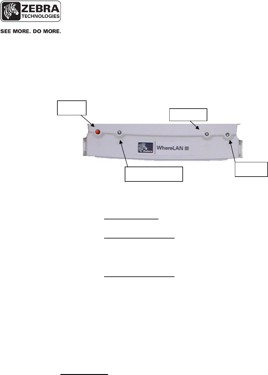
Upon power up, WhereLAN III executes a self-boot process. The boot
process takes between 45 to 60 seconds. If a fault occurs during the boot
process, the unit may reset and restart the boot process. During that process,
the four LEDs blink in a sequence to indicate the current stage of the power
up boot process. The LED Process is as follows after initial power is applied.
• 1 LED (Power): The Boot Loader is loading the Kernel.
• 4 LED’s : The Kernel is initialized and is loading the applications,
JFFS2 and CRAM File system
• 1 LED (Power): The Application is loading the FPGA’s and DSP’s
• 2 LED’s (Power and Tag Reception): The unit is initializing the
FPGA’s and DSP’s.
• 1 LED (Power): Unit is booted and ready for operations.
Figure 1 LOS-5000 LED's
Location Sensor
Outdoor
Omni
Antenna
P
ower/
H
ealth
Tag
Reception Ethernet
WLAN
___________________________________________________________________________
WhereLAN III User’s Guide
___________________________________________________________________________ 15
User’s Guide, WhereLAN III draft D1675 rev F
© Copyright Zebra Technologies, 2012
Zebra Confidential
Once the boot process is complete, the LEDs revert to their standard
functions indicating power/health, tag status, Ethernet, and Wi-Fi.
• Power/Health LED: Indicates unit has power and general health of
unit.
o State 1 Steady ON: When the Power LED is steady on, the
unit is healthy and sitedata has been received and is correct.
o State 2 80% Duty Cycle: The Power LED is ON for close to
80% of the time and OFF for a brief period. This indicates
either sitedata has not been received or that there is a
problem with site data.
o State 3 50% Duty Cycle: The Power LED blinks ON for 1
Second and OFF for 1 Second. This indicates a health check
has failed and possible hardware problem. For example, the
unit is either not blinking its embedded tag or is not receiving
its embedded tag.
• Tag Reception LED: Blinks when WhereTag signals are received.
• Ethernet LED: Is on solid when has connection to an Ethernet
network.
• WLAN LED: Is on solid when Wi-Fi connection is established.
See Appendix F: For Complete Boot Sequence details.
5.1.1 LED Functions
Power
Tag Reception
Ethernet
WLAN

___________________________________________________________________________
WhereLAN III User’s Guide
___________________________________________________________________________ 16
User’s Guide, WhereLAN III draft D1675 rev F
© Copyright Zebra Technologies, 2012
Zebra Confidential
5.2 WhereLAN III Interface
After the WhereLAN III has completed its boot process, it is possible to
communicate with the unit via the following methods.
Do not attempt to communicate with the WhereLAN III it has completed
the first stage of the boot process (i.e., left LED is solid). Doing so will
stop the boot process. The unit must be reset to clear this condition.
These units are configured using:
• SSH (Secure Shell 2) via Ethernet (preferred)
• WhereWand
• Hyperterminal (or any terminal emulation software) via serial port
SSH is the preferred method of communicating with the WhereLAN III.
Use the HyperTerminal is for initial set-up before being installed on a
network for setting static IP addresses, if DHCP is not used. In addition
to SSH, WhereLAN III also supports Telnet, but this protocol is disabled
by default. To use Telnet, you must first enable it via accessing the
WhereLAN III configuration menu via SSH or a serial port connection.
However, enabling Telnet is not recommended as it sends user name and
passwords across the network in the clear.
The Ethernet Communication Parameters are:
• 10/100 Mb/s
• CAT 5 cable/ RJ-45 plug
____________
Note
____________
____________
Note
____________

___________________________________________________________________________
WhereLAN III User’s Guide
___________________________________________________________________________ 17
User’s Guide, WhereLAN III draft D1675 rev F
© Copyright Zebra Technologies, 2012
Zebra Confidential
Hyperterminal via Serial Port
Communication Parameters:
• Null-modem cable, 9-pin female to 9-pin female
• 19200 baud, RS-232c
• 8 data bits, 1 stop bit, no parity, no hardware flow control
HyperTerminal may be used to configure the sensor before connecting it to a
network with a DHCP server, or when a rare fault occurs during the first stage
of the boot process, or if visibility to the boot process is needed for debugging
installation problems.
WhereLAN III supports Secure Shell (SSH), SSH2 being preferred over
SSH1. Either the IP address or host name of the unit must be known in order
to establish an SSH session.
An SSH session may be established using a freely available application called
OpenSSH (supplied by your Zebra Professional Services staff or visit
http://openssh.com for further details, but requires the ssh_zebra_rsa_key
available from Professional Services). Alternatively, other applications, such
as PuTTY, may be used as well, but will require the conversion on the
ssh_zebra_rsa_key into the appropriate format.
To establish the SSH session, you must use Zebra-supplied key, called
“ssh_host_rsa_key” and the “blowfish” passphrase.
The following section shows how to use the OpenSSH application.
5.2.1 Establishing an SSH Connection
___________________________________________________________________________
WhereLAN III User’s Guide
___________________________________________________________________________ 18
User’s Guide, WhereLAN III draft D1675 rev F
© Copyright Zebra Technologies, 2012
Zebra Confidential
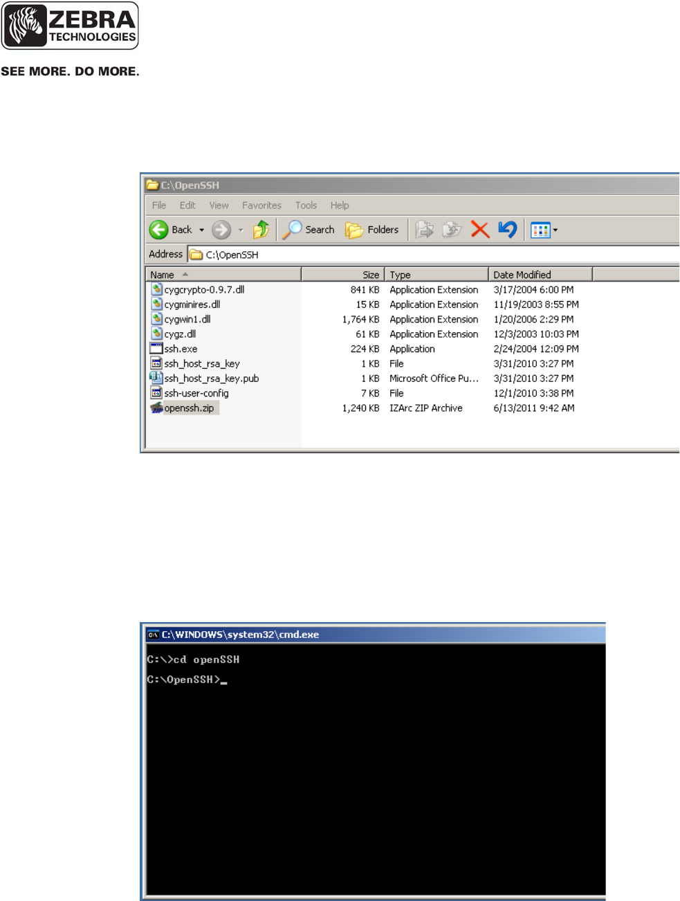
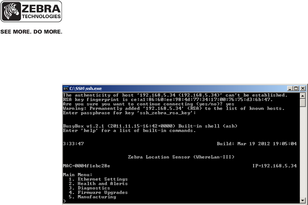
The provided zip archive contains all you need to use OpenSSH. Unzip the
file and put it anywhere on your hardrive.
1. Launch a command prompt, and change directory to the folder where you
placed the executable ssh.exe file, for example, “C\OpenSSH”.
___________________________________________________________________________
WhereLAN III User’s Guide
___________________________________________________________________________ 19
User’s Guide, WhereLAN III draft D1675 rev F
© Copyright Zebra Technologies, 2012
Zebra Confidential
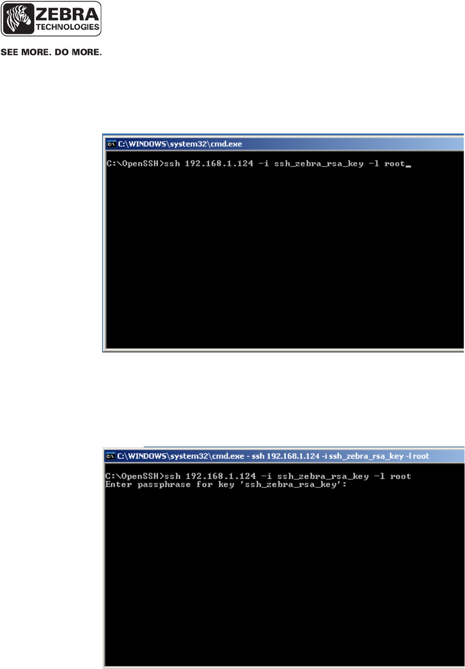
2. Enter the following command at the command prompt:
‘ssh <ip-address> -i ssh_zebra_rsa_key –l root’
Note: The first time you do this from most computers you will be told
“can’t establish….” And it will ask you “are you sure?”…enter ‘yes’
3. The application will prompt you for a passphrase, use: ‘blowfish’
___________________________________________________________________________
WhereLAN III User’s Guide
___________________________________________________________________________ 20
User’s Guide, WhereLAN III draft D1675 rev F
© Copyright Zebra Technologies, 2012
Zebra Confidential
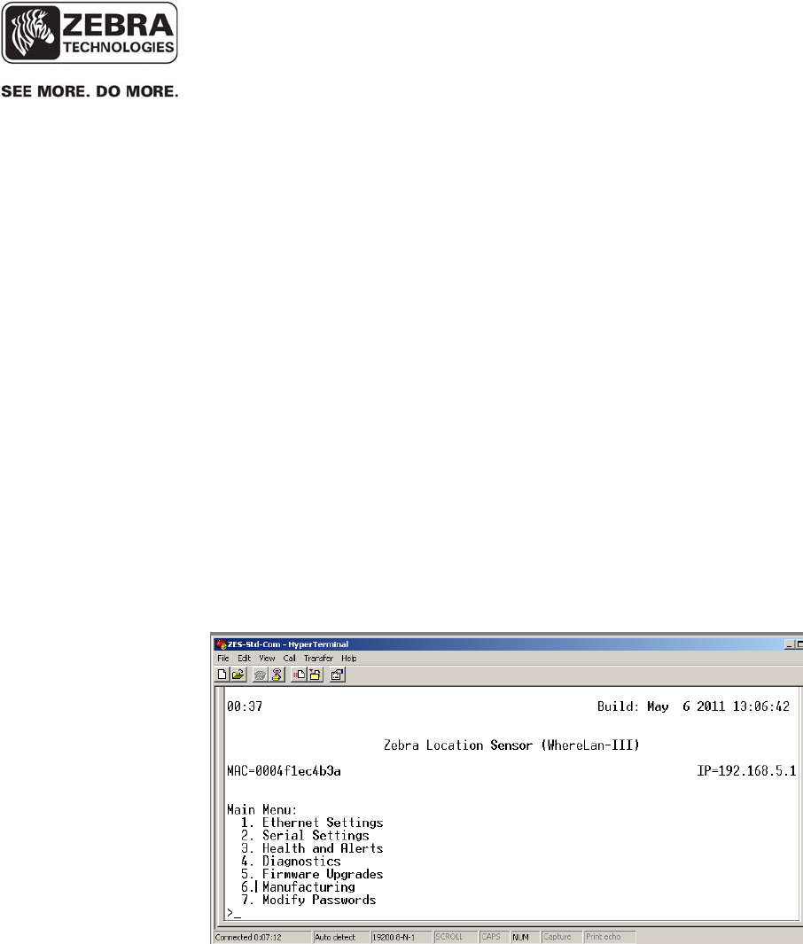
4. WhereLAN III then presents secure access to its Configuration menu.
The WhereLAN-III comes shipped with Telnet Disabled as added network
security. However for certain installation and/or customers Telnet may be
Enabled via the Menu System.
The enabling of Telnet is done via the numbered menu system either through
HyperTerminal or SHH, either will method will provide the same Menu
structure. The following example is shown using a direct connection with a
Null Modem Serial cable and HyperTerminal Session.
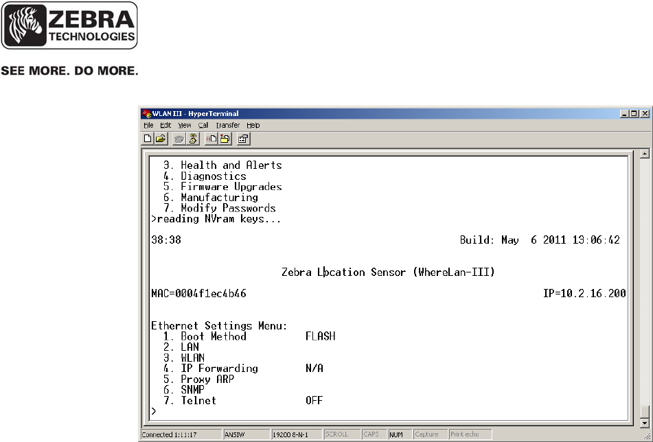
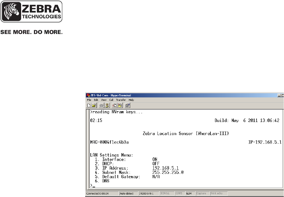
• From the Main Menu select the number that corresponds to ‘Ethernet
Settings’. The WhereLAN III application shows the following sub-
menu:
5.2.2 Enabling Telnet
___________________________________________________________________________
WhereLAN III User’s Guide
___________________________________________________________________________ 21
User’s Guide, WhereLAN III draft D1675 rev F
© Copyright Zebra Technologies, 2012
Zebra Confidential
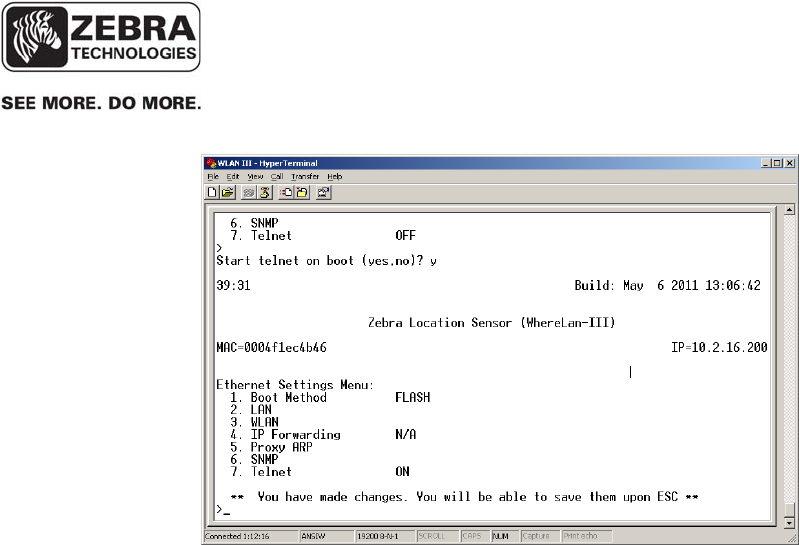
• Next select the number that corresponds to ‘Telnet’ and respond with y
to enable (or n to disable) Telnet.
___________________________________________________________________________
WhereLAN III User’s Guide
___________________________________________________________________________ 22
User’s Guide, WhereLAN III draft D1675 rev F
© Copyright Zebra Technologies, 2012
Zebra Confidential
Press the ESC key and enter the “ff2” password when prompted. The unit
will update NVRAM, save your changes, and ask if you wish to reset the unit.
After reset, the unit will boot with Telnet support.
Note Telnet User and Password are as follows.
User: root
Password: password

___________________________________________________________________________
WhereLAN III User’s Guide
___________________________________________________________________________ 23
User’s Guide, WhereLAN III draft D1675 rev F
© Copyright Zebra Technologies, 2012
Zebra Confidential
5.3 WhereLAN III MAC/ IP Address Configuration
WhereLAN IIIs connect to an IP network over an Ethernet or Wi-Fi interface
using TCP/IP, UDP, and other standard network protocols. For the LOS-
5000-00AB, both the Location Sensor and the embedded Client Card must be
independently configured with its own unique IP addresses or for DHCP
address assignment. The IP address of each LS must be recorded and entered
into the site configuration file, which contains the configuration information
for each LS, including its location, and MAC address. This is for versions of
VSS prior to the 4.0.5.2 release.
The WhereLAN-III device, running appropriate firmware V5.0.1 or later, will
automatically generate a link-local IPv6 address after booting up. However,
in order to acquire a global IPv6 address, which is needed for IPv6
communication with the VSS server, there must be an IPv6 router on the
network having the following configuration:
• Allow local IPv6 traffic with a global.
• IPv6 network prefix (such as, for example, 2001:470:87c4:1000::/64)
• Enable neighbor discovery/route advert. protocol
NOTE: The global IPv6 network prefix is a globally unique address and
can be used inside or outside of internal networks. You need to apply for
and obtain a global IPv6 network prefix for your network (for example,
see www.tunnelbroker.net ). This is a task typically performed by IT
personnel responsible for the network.
If additionally you would like to assign a fixed IPv4 address to a
WhereLAN-III, you can do so via the sensor menu, which can be accessed
via Telnet (if enabled) or SSH client, or direct connect with serial cable.
5.3.1 Activating IPv6 Transport
___________________________________________________________________________
WhereLAN III User’s Guide
___________________________________________________________________________ 24
User’s Guide, WhereLAN III draft D1675 rev F
© Copyright Zebra Technologies, 2012
Zebra Confidential
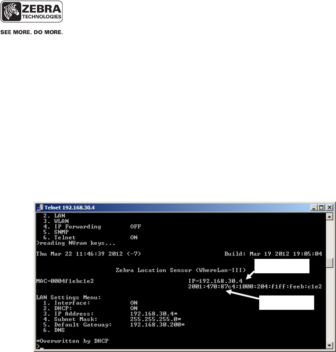
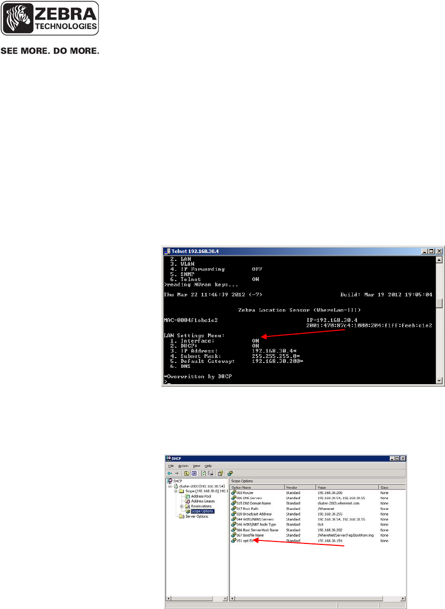
For example, if you Telnet to a sensor, you may see three IP addresses at
the top right of the window, as shown in the screenshot below:
• An IPv4 address, if one has been configured using the ‘Ethernet
Settings’ in the sensor menu (see screenshot).
• A global IPv6 address. This is the IPv6 address required for
communication with the VSS server using IPv6 transport.
• A link-local IPv6 address, automatically generated at boot up time
from the MAC address of the device
IPv4 address
IPv6 address
___________________________________________________________________________
WhereLAN III User’s Guide
___________________________________________________________________________ 25
User’s Guide, WhereLAN III draft D1675 rev F
© Copyright Zebra Technologies, 2012
Zebra Confidential
In order to have IPv6 network traffic (blinks, status information, etc.) between
the WhereLAN-III devices and the VSS server, the following requirements
must be fulfilled:
• The WhereLAN-III device must be able to acquire a global IPv6
address as described above.
• IPv6 must be enabled in the operating system (Windows) on the VSS
server.
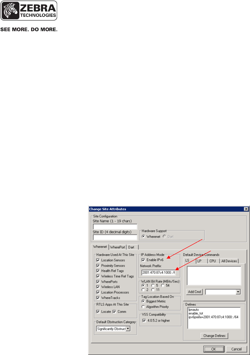
• The following steps must be followed in System Builder, which is the
tool that generates the sitedata.dat configuration file parsed by the VSS
services and the WhereLAN-III devices:
• Activate IPv6 in the ‘Change Site Attributes’ dialog window and enter the
global IPv6 network prefix that the IPv6 router on that network is using:
___________________________________________________________________________
WhereLAN III User’s Guide
___________________________________________________________________________ 26
User’s Guide, WhereLAN III draft D1675 rev F
© Copyright Zebra Technologies, 2012
Zebra Confidential
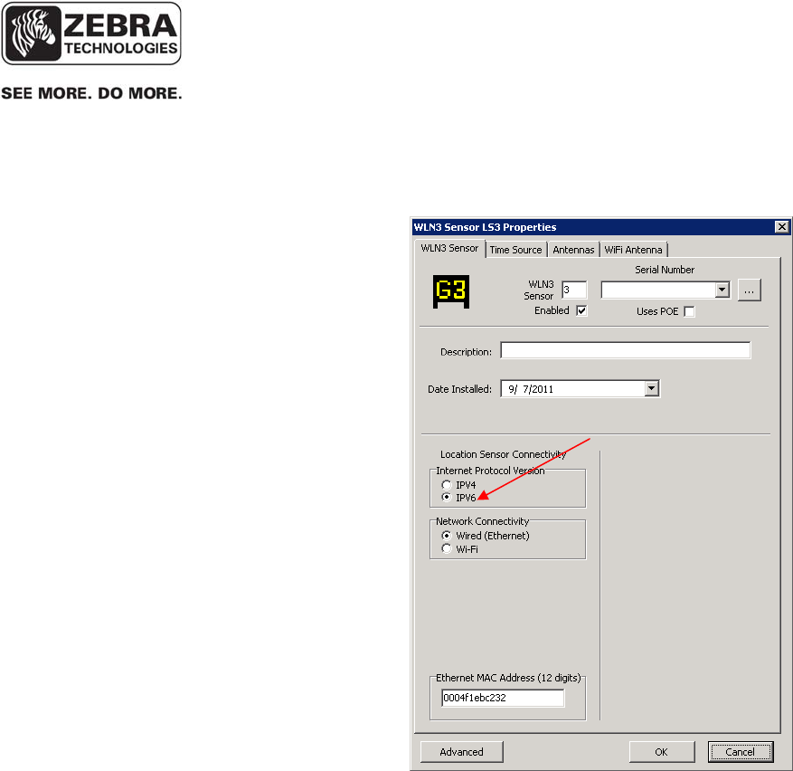
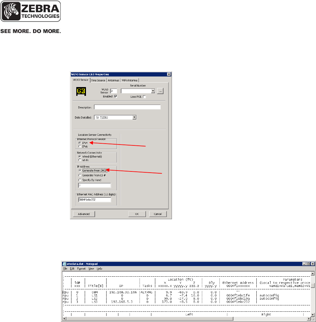
• Select IPv6 option in the Sensor Properties window:
___________________________________________________________________________
WhereLAN III User’s Guide
___________________________________________________________________________ 27
User’s Guide, WhereLAN III draft D1675 rev F
© Copyright Zebra Technologies, 2012
Zebra Confidential
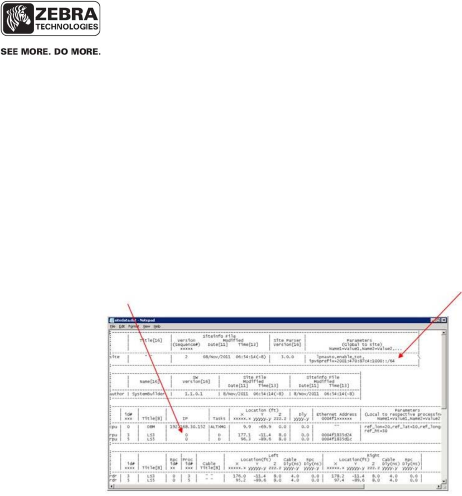
The resulting sitedata.dat generated by System Builder will include the following:
o A site define ipv6prefix specifying the global IPv6 network prefix used by
the IPv6 router on that network
o 0 (zero) IP address for all WhereLAN-III units that will communicate using IPv6
An example sitedata.dat is shown in the screenshot below:
NOTE: As usual, you need to restart the VSS services on the VSS server for
changes in sitedata.dat to take effect. Some changes require rebooting the
WhereLAN-III devices as well.
___________________________________________________________________________
WhereLAN III User’s Guide
___________________________________________________________________________ 28
User’s Guide, WhereLAN III draft D1675 rev F
© Copyright Zebra Technologies, 2012
Zebra Confidential
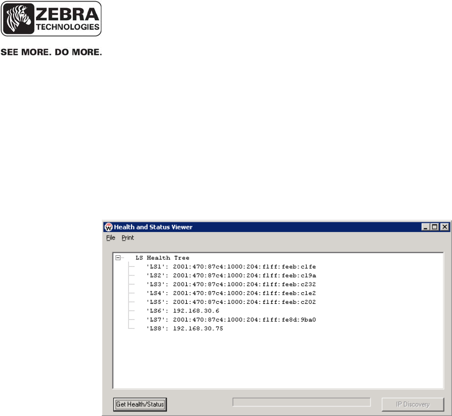
Once IPv6 transport between the VSS server and the WhereLAN-III devices
has been activated as described above, you can use the VSS diagnostics and
status tools as usual, but you will notice that the IPv6 address is used for
devices configured with the IPv6 option in System builder, as shown in the
Sensor Analyzer screenshot below:
5.3.2 VSS Tool Support for IPv6
___________________________________________________________________________
WhereLAN III User’s Guide
___________________________________________________________________________ 29
User’s Guide, WhereLAN III draft D1675 rev F
© Copyright Zebra Technologies, 2012
Zebra Confidential
It is possible to have a WhereLAN-III device automatically acquire an IPv4
address from a DHCP server. This IP assignment is dynamic and therefore the
assigned IP may change the next time the device is rebooted. To enable the
device to do so, the following steps are required:
o The DHCP option in the sensor menu needs to be turned ON:
o On the DHCP server, add scope option 151 (IP Address type) and point it to the IP
address of the VSS server:
5.3.3 IPv4 DHCP Dynamic IP for WhreLAN-III Devices
___________________________________________________________________________
WhereLAN III User’s Guide
___________________________________________________________________________ 30
User’s Guide, WhereLAN III draft D1675 rev F
© Copyright Zebra Technologies, 2012
Zebra Confidential
o In the Sensor Properties window in System Builder, select the IPv4 – DHCP option:
This will result in an entry for this sensor in sitedata.dat with a ‘0’ IP address and the
‘autoconfig’ define, as shown in the example below:
___________________________________________________________________________
WhereLAN III User’s Guide
___________________________________________________________________________ 31
User’s Guide, WhereLAN III draft D1675 rev F
© Copyright Zebra Technologies, 2012
Zebra Confidential
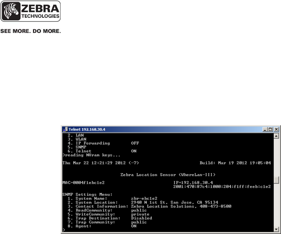
The WhereLAN-III firmware version 5.0.1 includes support for the SNMP
and DNS network protocols. The ‘Ethernet Settings’ menu in the sensor menu
includes menus to enable and configure these protocols, as shown in the
screenshots below:
5.3.4 SNMP and DNS Support in WHERELAN-III Devices

___________________________________________________________________________
WhereLAN III User’s Guide
___________________________________________________________________________ 32
User’s Guide, WhereLAN III draft D1675 rev F
© Copyright Zebra Technologies, 2012
Zebra Confidential
The WhereLAN-III MAC address is not directly compatible for replacing a
WhereLAN-II at an existing site that is running a version of VSS prior to
4.0.5.2, and WhereWAND’s that are running software that is from VSS prior
to 4.0.5.2.
Location Sensors use 4 unique embedded tags id’s, for Timing and Health.
These 4 unique embedded tag Id’s correspond to the Rf Transmit and TIC
ports (1, 2, and 3). The upper 32 bits of these four tag-ID’s MATCH bits 31
down to 2 of the unit’s MAC address. For this reason MAC addresses of
Location Sensor with, WhereLAN-II or WhereLAN-III, skip in a modulus of
4.
• For Example: In a WhereLAN-2 a MAC address might look like
0004F1AAA120, then the next MAC address of a WhereLAN-2,
in sequence, would be 0004F1AAA124.
• So this means for a WhereLAN-2 that there MAC address will
always end in either a 0, 4, 8, or C.
• For the above Example: Embedded tags for 0004F1AAA120:
Rf Port: F1AAA120
Tic1: F1AAA121
Tic2; F1AAA122
TIic3:F1AAA123
• The WhereLAN-III MAC addresses now ends in either 2, 6, A, and E.
5.3.5 WhereLAN-III MAC Legacy Compatibility

___________________________________________________________________________
WhereLAN III User’s Guide
___________________________________________________________________________ 33
User’s Guide, WhereLAN III draft D1675 rev F
© Copyright Zebra Technologies, 2012
Zebra Confidential
WhereLAN-III MAC addresses now ends in either 2, 6, A, and E. This new
MAC scheme allows more efficient use of the MAC space defined for this
product and easy recognition by users and the system in identify a unit as a
WhereLan-III or II by just looking at its MAC.
• However the embedded tags still follow the format of the WhereLAN-
II, meaning they MATCH bits 31 down to 2 of the unit’s MAC address
in order of RF Tag thru wired time ports.
• Older versions of the WhereWand FW assume that the lower 32-bits
MATCH between the MAC and the RF tag-ID. To fit WhereLan-III
into the MAC space it is now that sensors MATCH bits 31 down to 2.
• The embedded tags not matching the MAC address is causing issues,
because the WhereWAND uses the Rf embedded tag id to
communicate with the Location sensor.
The differences described above cause three main issues with the WhereLAN-
III MAC address and running an older version of VSS prior to VSS 4.0.5.2,
cause.
1. The Blink Service auto-generates a list of expected/known system
embedded tags based on the MAC address in SiteData. Entering the
MAC as listed on the unit, a legacy BlinkService will not generate a
proper list of embedded reference tags, and the Time Service will not
receive the embedded tag blinks it needs from the WhereLAN-III.
2. iSensor validates the MAC addresses in sitedata.dat match the MAC of
the Location sensors. With legacy iSensor, this causes red-lights on
the health and status display.
3. The WhereWAND’s download of the site configuration contain the
MAC addresses of each Location Sensor. The WhereWAND must use
the Rf embedded tag Id to communicate with the location sensor and
legacy WhereWand FW calculates the tag-ID incorrectly, resulting in
no-response from the specific sensor.
___________________________________________________________________________
WhereLAN III User’s Guide
___________________________________________________________________________ 34
User’s Guide, WhereLAN III draft D1675 rev F
© Copyright Zebra Technologies, 2012
Zebra Confidential
There are three ways to fix these issues.
1. The best is to have the customer site upgrade to VSS 4.0.5.2 or later,
which has the tools and system builder that take care of the issues
directly.
2. The next best is to see if the customer will allow new tools to be
loaded onto their system, if they require an approval time for full VSS.
The tools will be the System Builder and iSensor from the VSS 4.0.5.2
release. This will work with legacy version of VSS.
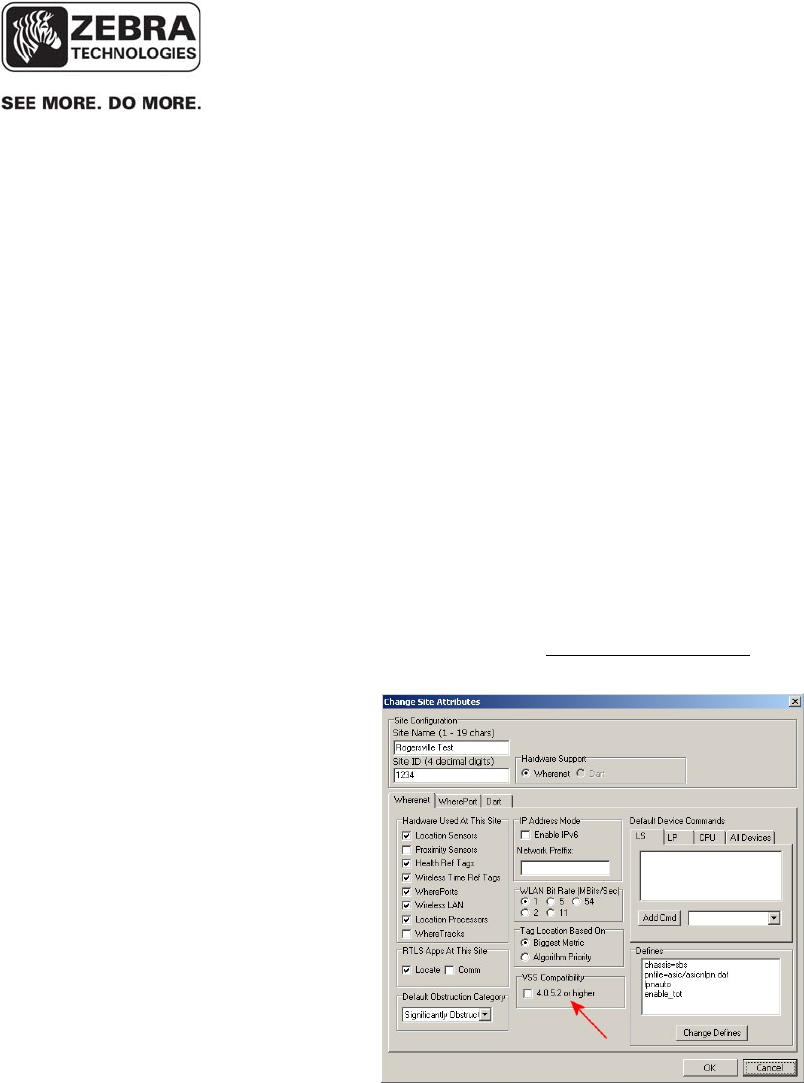
a. With this the MAC of the WhereLAN-III can be entered
accurately (as it is shown on the WHERELAN-III label) into
system builder, in the Location Sensor, WLN3 of the tree view.
Under the ‘Site Attributes’ tab, make sure the 4.0.5.2 VSS
Compatibility box is unchecked for legacy VSS systems. This
will save and publish the sitedata.dat in the correct form.

___________________________________________________________________________
WhereLAN III User’s Guide
___________________________________________________________________________ 35
User’s Guide, WhereLAN III draft D1675 rev F
© Copyright Zebra Technologies, 2012
Zebra Confidential
3. Otherwise, In legacy VSS systems using legacy tools, the MAC
address must be adjusted by subtracting 2 from the MAC address that
is listed on the unit, see table below.
ActualWLANIIIMACSystemBuilder
MACEntry
00‐04‐f1‐xx‐xx‐02 00‐04‐f1‐xx‐xx‐00
00‐04‐f1‐xx‐xx‐06 00‐04‐f1‐xx‐xx‐04
00‐04‐f1‐xx‐xx‐0A 00‐04‐f1‐xx‐xx‐08
00‐04‐f1‐xx‐xx‐0E 00‐04‐f1‐xx‐xx‐0C
NOTE:ThistableonlyappliestolegacyVSS,versionpriortoVSS
4.0.5.2
This will allow the WhereLAN-III’s to function in the Blink Service and have
the Time Service looking for the correct embedded tag Id’s. However with
legacy iSensor this will still display the unit as Red in Health and Status, for
the MAC mismatch. To fix the health indicator, you can consider just
replacing the iSensor executable with the one from VSS 4.0.5.2.
Failure to configure the WhereLAN III prior to operation may result in
an inoperative unit. Ethernet connected units installed on an operational
and reliable network with DHCP IP address assignment may be
configured post installation. All Wi-Fi connected units must be
configured with the appropriate Wi-Fi network parameters before
installation.
____________
Note
____________
___________________________________________________________________________
WhereLAN III User’s Guide
___________________________________________________________________________ 36
User’s Guide, WhereLAN III draft D1675 rev F
© Copyright Zebra Technologies, 2012
Zebra Confidential
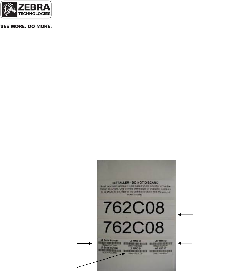
Each WhereLAN III is shipped with a label set containing one label (Figure 2)
with the bar coded MAC address of the unit and its Wi-Fi client (as
applicable) and three labels with the last six characters of the Location
Sensor’s MAC address in large type. Ensure that the label is correct by
matching the MAC address(es) on the loose label set with the MAC
address(es) listed on the back of the unit. Place the loose bar code label in the
site design document where indicated, and place one or more of the large type,
six character labels on the exterior of the Location Sensor in positions that are
visible after installation.
The MAC address label must be clearly marked on the exterior of the
Location Sensor housing in a position visible after installation.
`
Figure 2 Example of LOS-5000-00AB Label
Last 6 LS
MAC digits
Wi-Fi Client
MAC Address
Location Sensor
MAC Address
Location Sensor
Serial Number
____________
Note
____________
___________________________________________________________________________
WhereLAN III User’s Guide
___________________________________________________________________________ 37
User’s Guide, WhereLAN III draft D1675 rev F
© Copyright Zebra Technologies, 2012
Zebra Confidential
While there is no restriction to the IP address, it must match the address in the
Site file for that particular WhereLAN III. The IP address(es) can be static
assigned, or dynamically assigned via DHCP. If assigned through DHCP, the
DHCP server must contain the MAC address and corresponding IP address for
each of the Location Sensors (and Wi-Fi Client).
For networks utilizing DHCP, the IP address or host name of the site’s
RTLS server must be entered in the DHCP server. See the VSS User
Guide for more details on Network Autoconfig.
To configure the IP address of the Location Sensor:
Note the following configuration examples are done thru HyperTerminal.
• Connect to the Location Sensor using SSH, or HyperTerminal.
• Select the number that corresponds to ‘Ethernet Settings”1 and
confirm the unique MAC address for the Location Sensor.
____________
Note
____________
___________________________________________________________________________
WhereLAN III User’s Guide
___________________________________________________________________________ 38
User’s Guide, WhereLAN III draft D1675 rev F
© Copyright Zebra Technologies, 2012
Zebra Confidential
• Select 1 for setting Boot Method, Flash for internal image or Network
for image. (Flash is default and most commonly used).
• Select 2 for wired LAN Port IP setting or 3 WLAN client IP/DHCP
setting.
• Save the configuration changes by using ESC key entering the
password “ff2”.
• Note Changes take effect on unit reboot/reset.
• Confirm communication to the Location Sensor by “pinging” the
device from a DOS prompt.
___________________________________________________________________________
WhereLAN III User’s Guide
___________________________________________________________________________ 39
User’s Guide, WhereLAN III draft D1675 rev F
© Copyright Zebra Technologies, 2012
Zebra Confidential
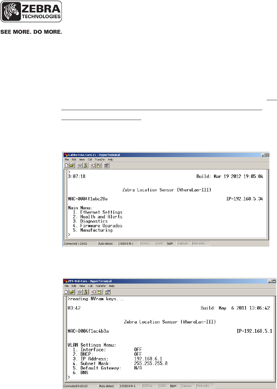
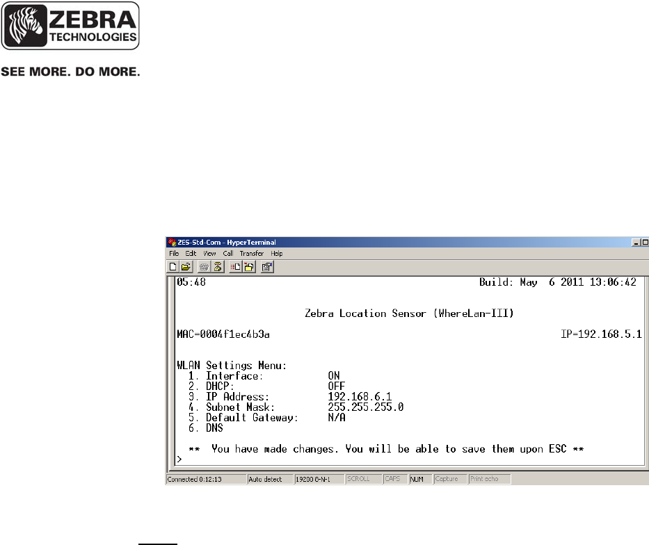
5.4 Wi-Fi Client Configuration (LOS-5000-00AB only)
The Wi-Fi client card embedded in the WhereLAN III must be configured
with the proper IP address or for DHCP set and the Interface must be ON. In
addition, the Wi-Fi network parameters, such as the SSID, and authentication
and encryption methods, must be configured in the wpa_supplicant, (See
sections 5.4.2 Configuring the Wi-Fi Network Parameters and 5.4.3
WPA_Supplicant Cautions)
From the Main Menu:
• Select Ethernet Settings.
• Under Ethernet Menu select 3 WLAN.
• Set 1. Interface to ON, then IP/DHCP settings.
___________________________________________________________________________
WhereLAN III User’s Guide
___________________________________________________________________________ 40
User’s Guide, WhereLAN III draft D1675 rev F
© Copyright Zebra Technologies, 2012
Zebra Confidential
• Save the configuration changes by using ESC key entering the
password “ff2”.
• Select either ‘yes’ or ‘no’ at this point, depending on if further
configuration needs to take place.. (A reset/reboot will be
required thought for all the changes to take effect.)
Note: Although the LOS-5000-00AB has two network interfaces (its Ethernet
and Wi-Fi ports) in the vast majority of cases, only its Wi-Fi port is actually
connected to an operational network. If enabled, the Ethernet port must be
configured to be on a different subnet than the Wi-Fi port. In this case, it is
recommended that a non-routable IP address be used such as
192.168.5.0/255.255.255.0, to enable local diagnostics via the Ethernet port.
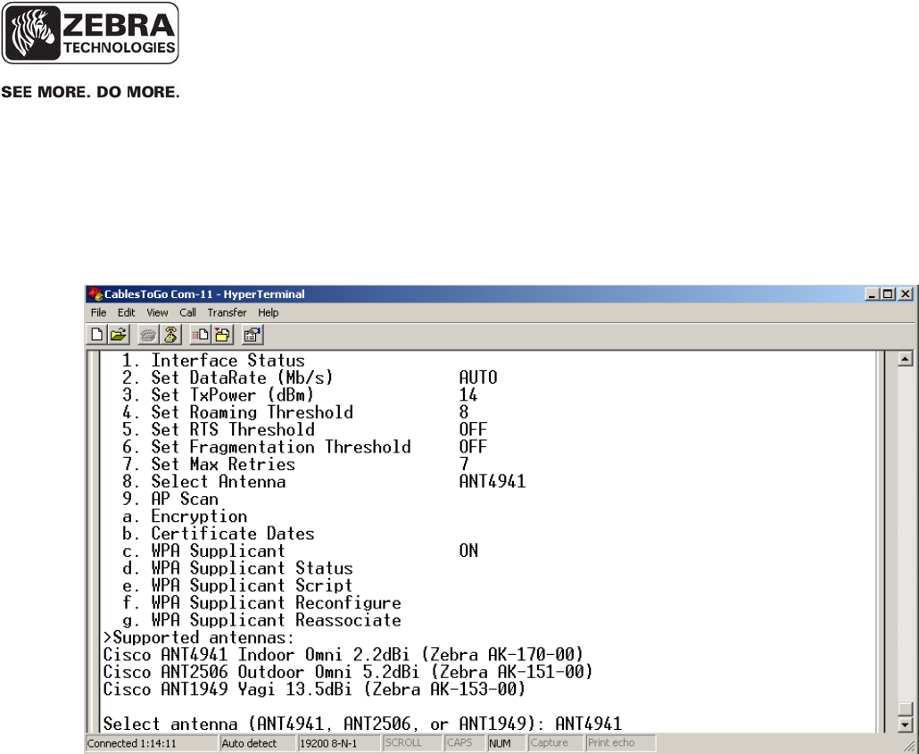
The Wi-Fi antenna setting is available in firmware versions V5.0.2 or later
(Build Date Apr 30 2012 or later). The antenna selection is set under
802.11Client Menu, which is reached from the Main Menu via the
Diagnostics Menu. There are currently three antenna choices to select from,
and these match the Wi-Fi antennas that are offered on the marketing price
list. The selection is entered under the “Select Antenna” menu item.
Antenna Options:
• AK-170-00 2.2dBi Dipole Antenna (Rubber Duck) , Selection ANT4941
• AK-151-00 5.2dBi Omni Antenna, Selection ANT2506
5.4.1 Setting Wi-Fi Antenna Type
___________________________________________________________________________
WhereLAN III User’s Guide
___________________________________________________________________________ 41
User’s Guide, WhereLAN III draft D1675 rev F
© Copyright Zebra Technologies, 2012
Zebra Confidential
From the Main Menu, select Diagnostics, and from the Diagnostics Menu select
802.11 Client. Then, in the 802.11 Client Menu, select the number that
corresponds to “Select Antenna”, and enter the value that corresponds to the
antenna that will be attached to the WhereLAN-III.
Escape “ESC” to save selection, ‘ff2’ is the password. The unit will need to be
rebooted for the setting to take effect.
All the Wi-Fi network parameters are under the control of a file called
wpa_supplicant.conf. In order to configure the WhereLAN III Wi-Fi client
card to access your network, you must first edit or create this file to match
your Wi-Fi network configuration and then upload the file onto the
WhereLAN III unit. The wpa_supplicant.conf file must be created or edited
with a Linux friendly text editor. Do not use Notepad or similar. A popular
free Linux editor is called VIM and is found at http://vim.sourceforge.net/.
5.4.2 Configuring the Wi-Fi Network Parameters

___________________________________________________________________________
WhereLAN III User’s Guide
___________________________________________________________________________ 42
User’s Guide, WhereLAN III draft D1675 rev F
© Copyright Zebra Technologies, 2012
Zebra Confidential
The process will be illustrated assuming a sample Wi-Fi network with the
following parameters.
a. SSID = ZEBRA
b. Security = WPA2, Pre-Shared Key (WPA2-PSK)
c. WPA2 passphrase = ZebraPassphrase2011
To match these Wi-Fi parameters, the wpa_supplicant.conf file is very simple
and is shown below:
Create your wpa_supplicant.conf file with your Linux-friendly editor and
place a copy of it on the RTLS Server’s ftproot directory. Placing the file in
this directory facilitates the upload process.
Uploading the wpa_supplicant.conf file onto the WhereLAN III Unit.
5.4.3 WPA_Supplicant Cautions
# A simple script file for WPA2-PSK with AES CCMP mode.
# The following line should not be changed. Otherwise, Wi-Fi will not work.
ctrl_interface=/var/run/wpa_supplicant
# Let wpa_supplicant take care of scanning and AP selection
ap_scan=2
# Network Block
network={
ssid="ZEBRA"
proto=WPA2
key_mgmt=WPA-PSK
pairwise=CCMP
group=CCMP
psk="ZebraPassphrase2011"
}

___________________________________________________________________________
WhereLAN III User’s Guide
___________________________________________________________________________ 43
User’s Guide, WhereLAN III draft D1675 rev F
© Copyright Zebra Technologies, 2012
Zebra Confidential
Important: The wpa_supplicant file, which controls security of the wireless
client card, is currently over written when upgrading the firmware on a
WhereLAN-III.
• Over writing the wpa_supplicant file can lead to loss of network
connection if the WhereLAN-III is wirelessly connected to the
network.
• Once upgraded the wpa_supplicant file will revert to its original
configuration.
• Recovery WILL require direct connection to the unit.
Solution: The issue of over writing the wpa_supplicant file can be avoided by
editing the WhereLAN-III ‘upgrade.txt’ script file that is distributed with the
WhereLAN-III firmware files. The files will be located in a directory under the
/inetpub/ftproot/server\G3v501.
• The script file is the first to be read by the WhereLan-III and is
subsequently used by the WhereLan-III to control which of the four
firmware files (bootloader.bin, uImage, rootfilesys, and JFFS2) are to
be uploaded to the WhereLan-III during the upgrade process.
• The wpa_suplicant.conf file is stored within the JFFS2 image. When
JFFS2 is upgraded, the site specific wpa_suplicant.conf file is replaced
with the default found in the released JFFS2 image.
• Modifications to the upgrade.txt script file are supported to enable the
WhereLan-III to temporarily save the site specifc wpa_supplicant.conf
file and restore it after the upgrade of JFFS2 completes.
• The necessary command line for saving and restoring the
wpa_suplicant.conf file is present in the upgrade.txt script, but is
commented out and therefore causes no effect.
• Modifying the wpa_supplicant.conf file can be done by removing the
“#” (indicator for a comment line)from in front of the
F1=”wpa_supplicant/conf” line.
o Note ‘#’ is the script’s language for indicating the line is a
comment and contains no instructions. Removing the ‘#’
causes the script to execute the instruction on that line.
o The upgrade.txt file must be edited with a Linux friendly text
editor. Do not use Notepad or similar as it WILL corrupt the

___________________________________________________________________________
WhereLAN III User’s Guide
___________________________________________________________________________ 44
User’s Guide, WhereLAN III draft D1675 rev F
© Copyright Zebra Technologies, 2012
Zebra Confidential
file. A popular free Linux editor is called VIM and is found at
http://vim.sourceforge.net/ .
Example excerpt from a default upgrade.txt script file:
###############################################################
# List JFFS2 files and/or directories (F0-FN, N<10) to be restored
###############################################################
#F0="wpa_supplicant.conf_reference"
#F1="wpa_supplicant.conf"
Modified example excerpt from a default upgrade.txt script file to cause the
wpa_supplicant.conf file to be save d and later restored:
###############################################################
# List JFFS2 files and/or directories (F0-FN, N<10) to be restored
###############################################################
#F0="wpa_supplicant.conf_reference"
F1="wpa_supplicant.conf"
NOTE the removed “#” (from the fourth line) in front of the F1 as shown above.
Engineering is in planning on how to deliver a standard set of firmware files and
scripts that may default to automatic save/restore.
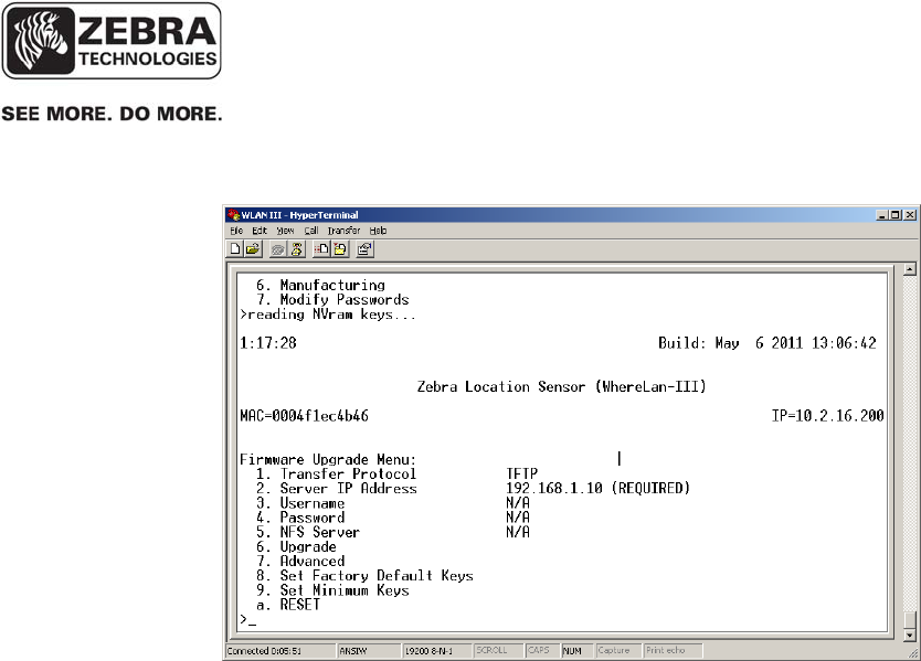
5.5 WPA Supplicant Upload
The following instructions will demonstrate on how to upload a
wpa_supplicant.conf file to the WhereLAN-III.
From the Main Menu, select the number that corresponds to ‘Firmware
Upgrade’.
___________________________________________________________________________
WhereLAN III User’s Guide
___________________________________________________________________________ 45
User’s Guide, WhereLAN III draft D1675 rev F
© Copyright Zebra Technologies, 2012
Zebra Confidential
Now Select the ‘Transfer Protocol’ (either TFTP default, FTP, or NFS) and set
the ‘Server IP Address’ of the server where the files are locate. Ensure the
tftp and/or ftp service is enabled on the computer that contains the
wpa_supplicant.conf file.
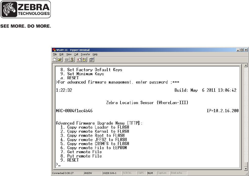
Now, select the item number that corresponds to ‘Advanced’, and enter the ff2
password. The WhereLAN II present the following menu.
___________________________________________________________________________
WhereLAN III User’s Guide
___________________________________________________________________________ 46
User’s Guide, WhereLAN III draft D1675 rev F
© Copyright Zebra Technologies, 2012
Zebra Confidential
___________________________________________________________________________
WhereLAN III User’s Guide
___________________________________________________________________________ 47
User’s Guide, WhereLAN III draft D1675 rev F
© Copyright Zebra Technologies, 2012
Zebra Confidential
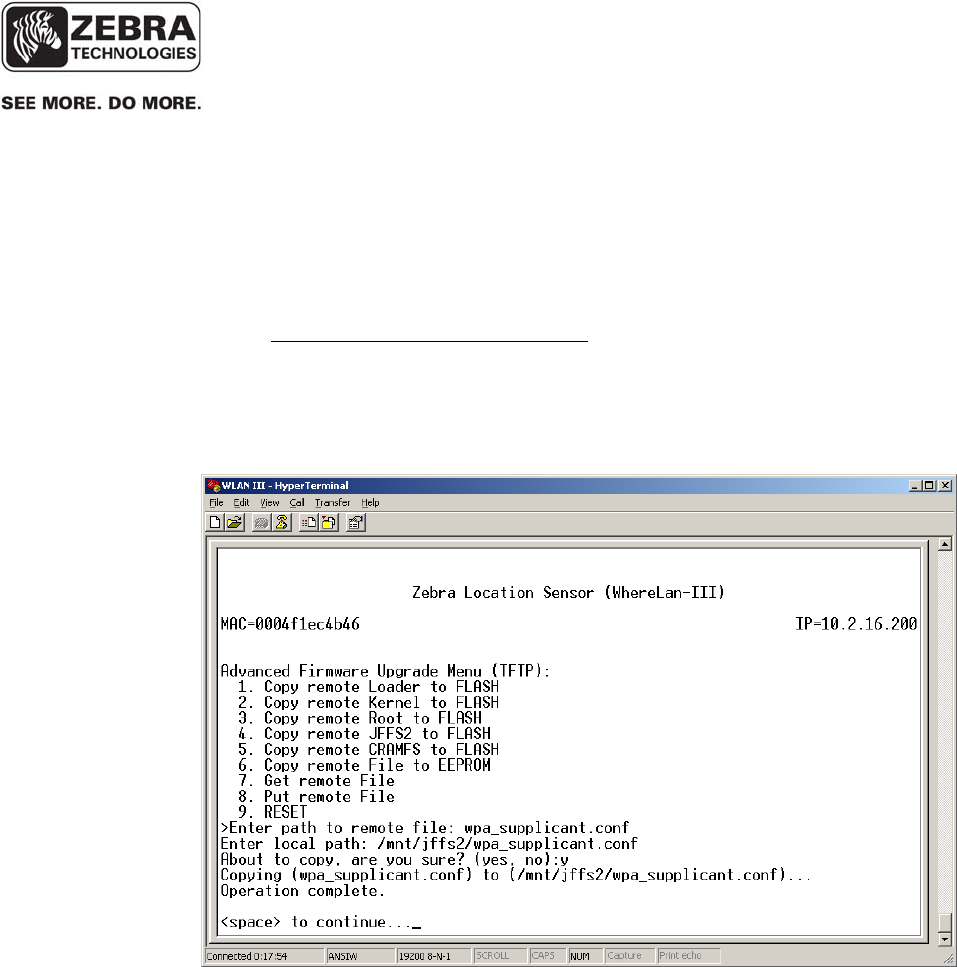
• Now, select 7, ‘Get remote file’. The WhereLAN III asks for the path
to the remote file. As you have placed the file in the server’s root
directly, simply enter ‘wpa_supplicant.conf’.
• Now, the WhereLAN III asks for a local path, i.e., where the file
should be placed in the WhereLAN III itself. Enter
‘/mnt/jffs2/wpa_supplicant.conf’. Be sure to enter the path and file
names correctly, as an error here will prevent normal Wi-Fi operations.
WhereLAN III asks you to confirm before the file is uploaded. Accept
by entering y. When the operation completes, your screen should
look like this.
• Now, that the wpa_supplicant.conf file has been uploaded, you must
enable wpa_supplicant processing on the WhereLAN III itself.
___________________________________________________________________________
WhereLAN III User’s Guide
___________________________________________________________________________ 48
User’s Guide, WhereLAN III draft D1675 rev F
© Copyright Zebra Technologies, 2012
Zebra Confidential
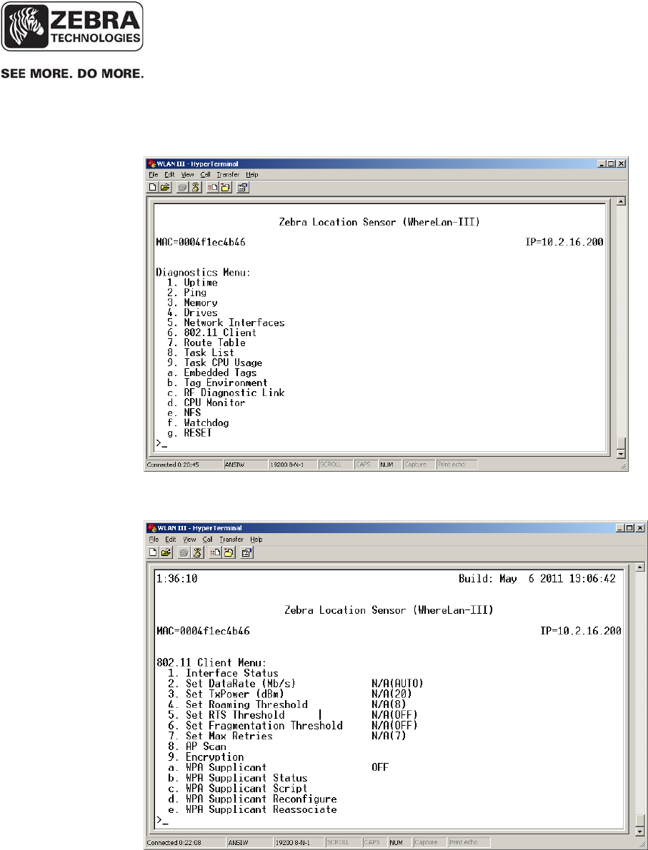
• From the Main Menu, select the number that corresponds to,
‘Diagnostics’. This will display the Diagnostic menu as shown below.
• Next select the number that corresponds to, ‘802.11 client’.
___________________________________________________________________________
WhereLAN III User’s Guide
___________________________________________________________________________ 49
User’s Guide, WhereLAN III draft D1675 rev F
© Copyright Zebra Technologies, 2012
Zebra Confidential
• And now, the item that corresponds to, ‘WPA Supplicant’, respond
‘yes’ to enable wpa_supplicant operation.
• Press ESC to save changes, and enter the ff2 password, and space to
continue.
• The unit must be reset in order for wpa_supplicant processing to take
effect.
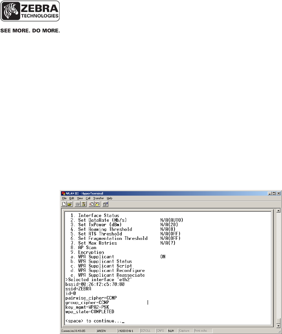
Verify the unit’s Wi-Fi network connection is operation.
• From the Main Menu select the number that corresponds
‘Diagnostics’.
• In the Diagnostics Menu, select the number that corresponds to
‘802.11 Client’.
• In the 802.11 Client Menu, select the item that corresponds to ‘WPA
Supplicant Status’ and WhereLAN III will display its Wi-Fi
association status, as shown below.
Important: It is good practice to verify the operation of the Wi-Fi before
having the unit installed.
___________________________________________________________________________
WhereLAN III User’s Guide
___________________________________________________________________________ 50
User’s Guide, WhereLAN III draft D1675 rev F
© Copyright Zebra Technologies, 2012
Zebra Confidential
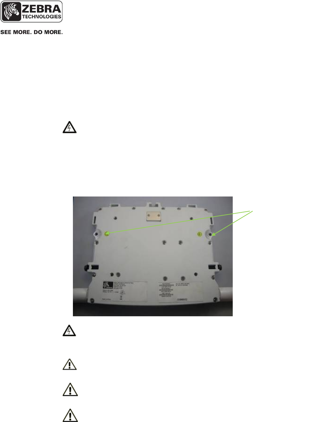
Earth Ground Locations.
Bolt Size 8mm. Max
Length 25mm.
6 INSTALLATION AND MOUNTING
Read Installation and Instruction sheet included with the Location Sensor as
well as all Safety and Installation Warnings/Cautions before installing. Follow
the Site Design document for installed location.
6.1 Safety and Installation Warnings and Cautions
Warning - Warning - Electrical Shock: A protective earthing
conductor with green and yellow insulation, minimum of 18 AWG, shall be
installed to the protective earthing terminal of the metal enclosure when I/O or
power cables are routed outdoors. National electrical codes shall be followed
to install facility protective earthing conductor to the protective earthing
terminal.
Figure 3 Safety and
Warnings
Warning - Electrical Shock: No operator serviceable parts inside. Refer
servicing to qualified personnel. To prevent electrical shock, do not remove
covers.
Caution - The Location Sensor hardware must be installed by a qualified
service technician
Caution - Use of Zebra external power supply is limited to indoor use
and a max 40° C environment. Only use Zebra approved power supplies.
Caution - The Timing Sync cable use is limited to indoor only.
___________________________________________________________________________
WhereLAN III User’s Guide
___________________________________________________________________________ 51
User’s Guide, WhereLAN III draft D1675 rev F
© Copyright Zebra Technologies, 2012
Zebra Confidential
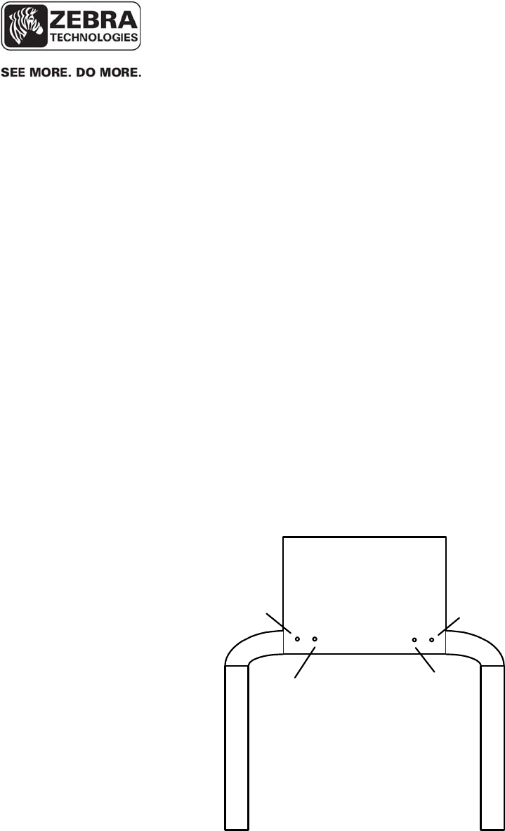
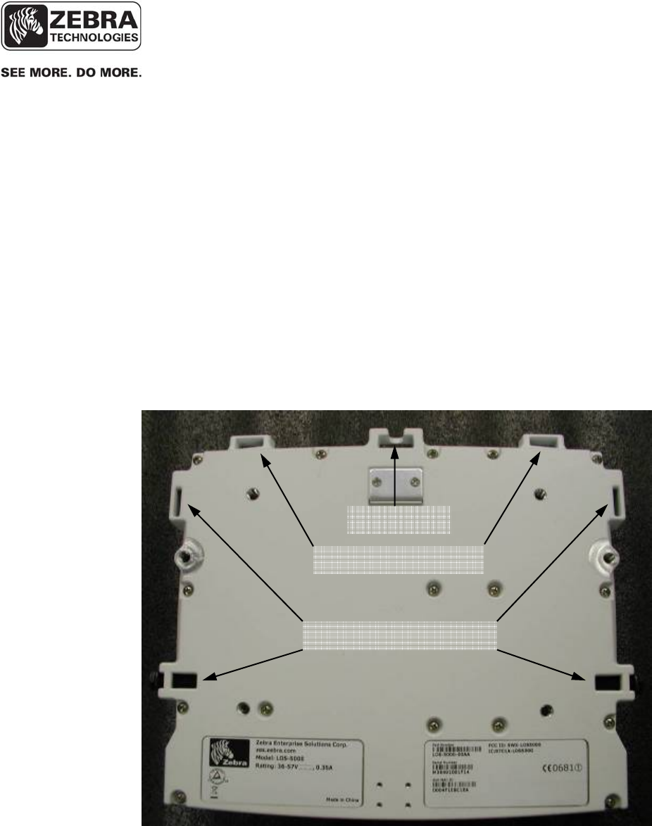
6.2 Mounting
The site design specifies the location of the Location Sensor(s) to provide
optimum system performance. It is critical that the Location Sensor is
mounted in a position which provides good RF visibility to the tracked assets.
Thus the Location Sensor must be mounted exactly in the position specified in
the site design document
The Location Sensor has two methods of mounting .The first can be hung
using nut pocket on top for attachment to accept a 3/8 in (10 mm) threaded
rod and jam nut, useful when using a beam clamp type of hanger. The second
method of mounting is a pole mount hardware kit is available separately, ZES
Part Number RM-510-00 Mounting Bracket, Pole Mount.
Figure 4 Mounting Points
Failure to mount the Location Sensor in the exact position specified in the
site design will result in erroneous or non-locates of the tracked assets.
____________
Note
Safet
y
Lan
y
ard Points
Nut Pocket
Mountin
g
Bracket Points
___________________________________________________________________________
WhereLAN III User’s Guide
___________________________________________________________________________ 52
User’s Guide, WhereLAN III draft D1675 rev F
© Copyright Zebra Technologies, 2012
Zebra Confidential
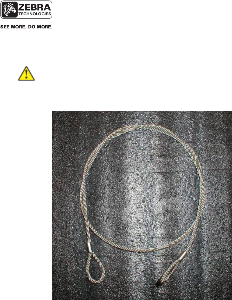
____________
For safety it is strongly recommend that a Safety Lanyard be employed with
either mounting method. The Safety Lanyard points are large enough to
accept a 3/16” loop style wire rope. Stainless Steel Rope is recommended.
____________
Figure 5 Safety Lanyard
___________________________________________________________________________
WhereLAN III User’s Guide
___________________________________________________________________________ 53
User’s Guide, WhereLAN III draft D1675 rev F
© Copyright Zebra Technologies, 2012
Zebra Confidential
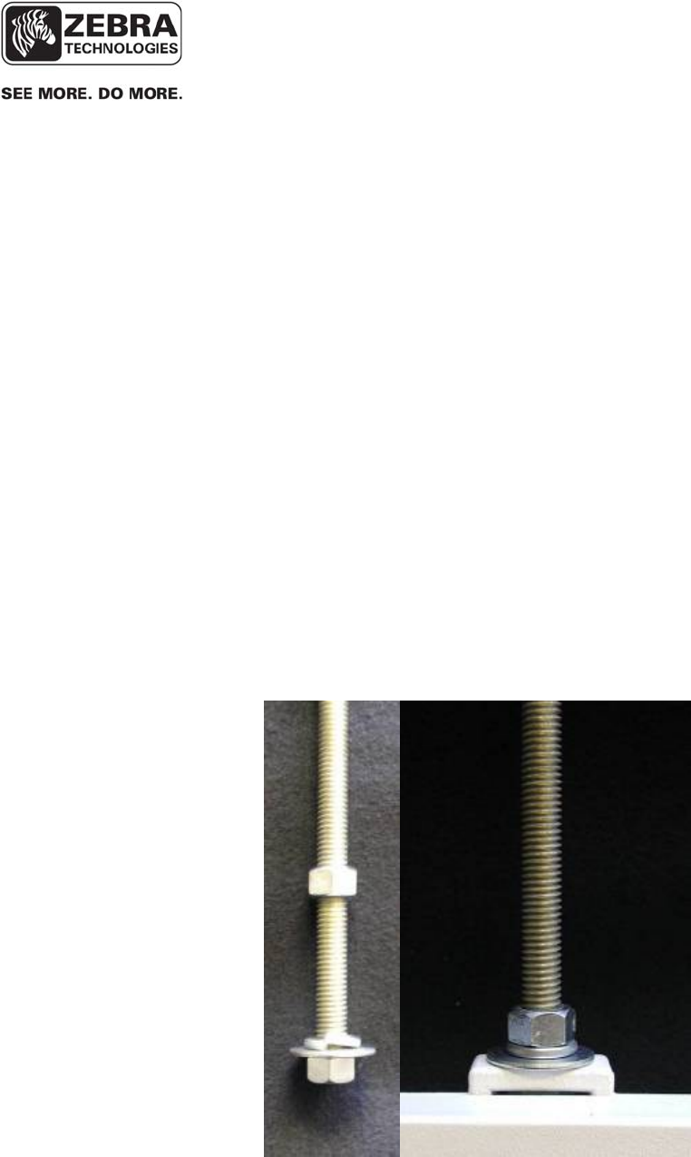
6.3 3/8ths Threaded Rod
The Location Sensor can be hung via a 3/8 inch (10 mm) threaded rod per the
following instructions. This type of mounting is intended for indoor
installations only, if mounting outdoors use the Pole Mount Kit described in
Sections 6.4. The required supports, threaded rod, nuts, etc., are not included.
• Cut the threaded rod to the desired length and install it directly above
the desired Location Sensor position.
• Thread one nut up 2 in (50 mm) from the bottom of the threaded rod,
with Lock Washer and Washer.
• Place the second nut onto threaded rod, flush with the end of the
threaded rod and install the Location Sensor.
• Tighten the upper nut down on top of the Location Sensor housing.
Figure 6 Threaded-Rod
___________________________________________________________________________
WhereLAN III User’s Guide
___________________________________________________________________________ 54
User’s Guide, WhereLAN III draft D1675 rev F
© Copyright Zebra Technologies, 2012
Zebra Confidential
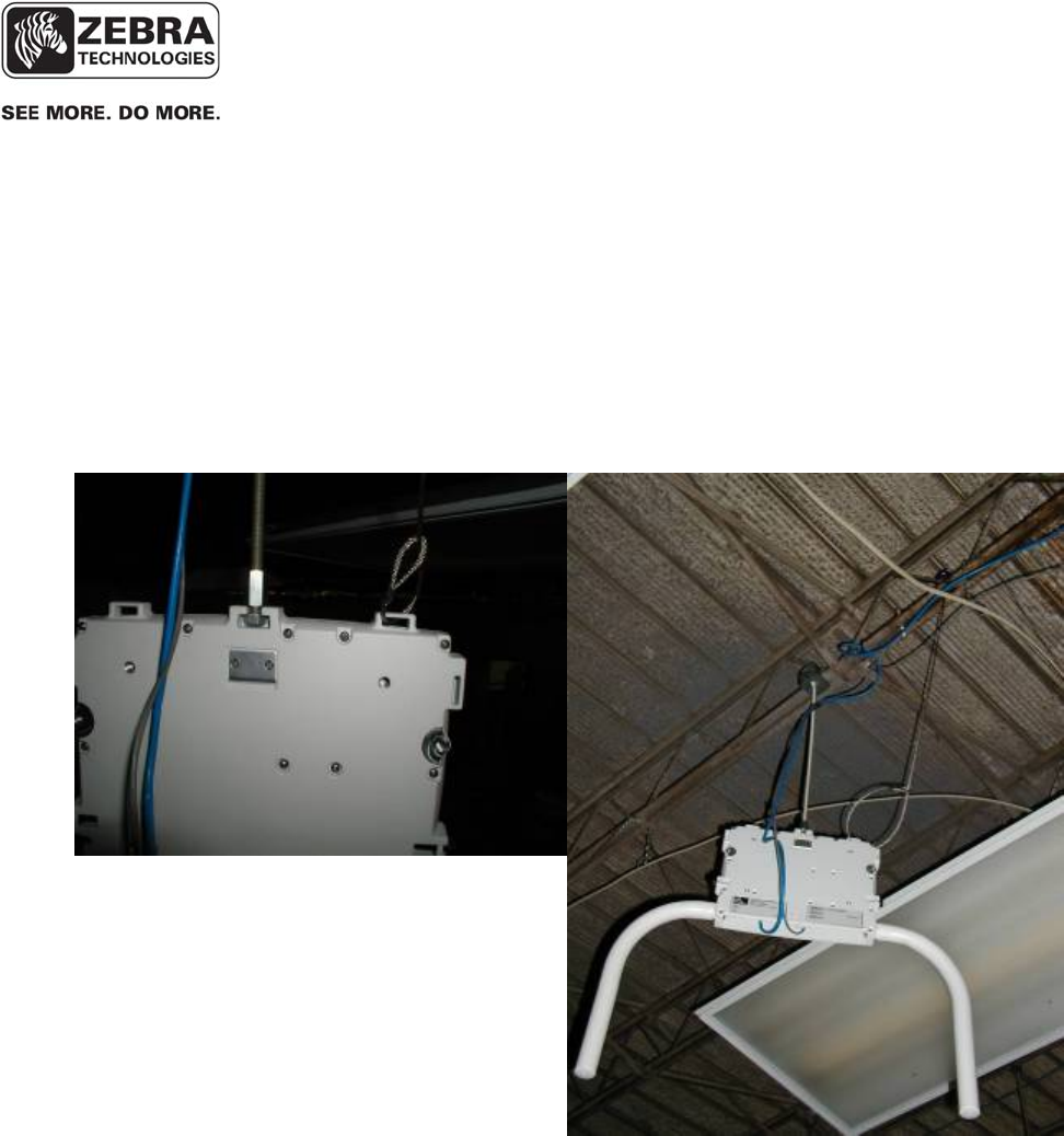
For Location Sensor installation using the Threaded Rod Mounting, it must
also be secured to the building infrastructure with a safety lanyard through the
one of the rectangular loops on top the casting. See below in Figure 7 Safety
Lanyard.
Figure 7 Safety Lanyard
6.3.1 Safety Lanyard with Threaded Rod
___________________________________________________________________________
WhereLAN III User’s Guide
___________________________________________________________________________ 55
User’s Guide, WhereLAN III draft D1675 rev F
© Copyright Zebra Technologies, 2012
Zebra Confidential
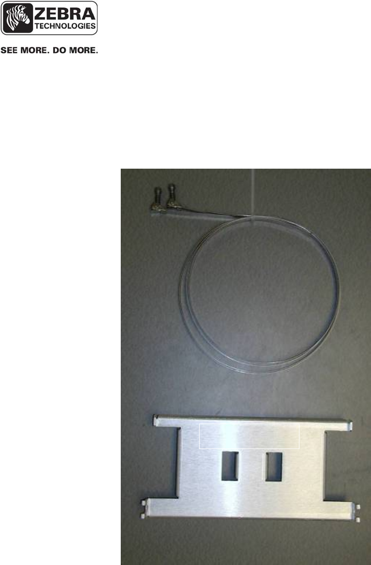
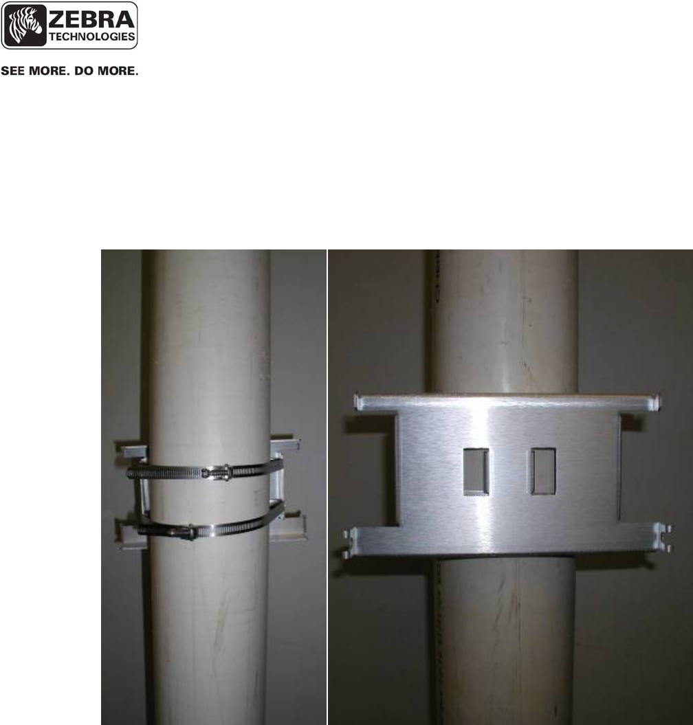
6.4 Pole Mount Kit
The pole mount kit, catalog number RM-510-00, must be ordered separately.
The pole mount kit will allow the Location Sensor to be mounted to either a
pole or 1-1/4” metal channel framing, per the instructions included with the
pole mount kit.
Figure 8 Pole
Mount Kit
Top of Bracket
___________________________________________________________________________
WhereLAN III User’s Guide
___________________________________________________________________________ 56
User’s Guide, WhereLAN III draft D1675 rev F
© Copyright Zebra Technologies, 2012
Zebra Confidential
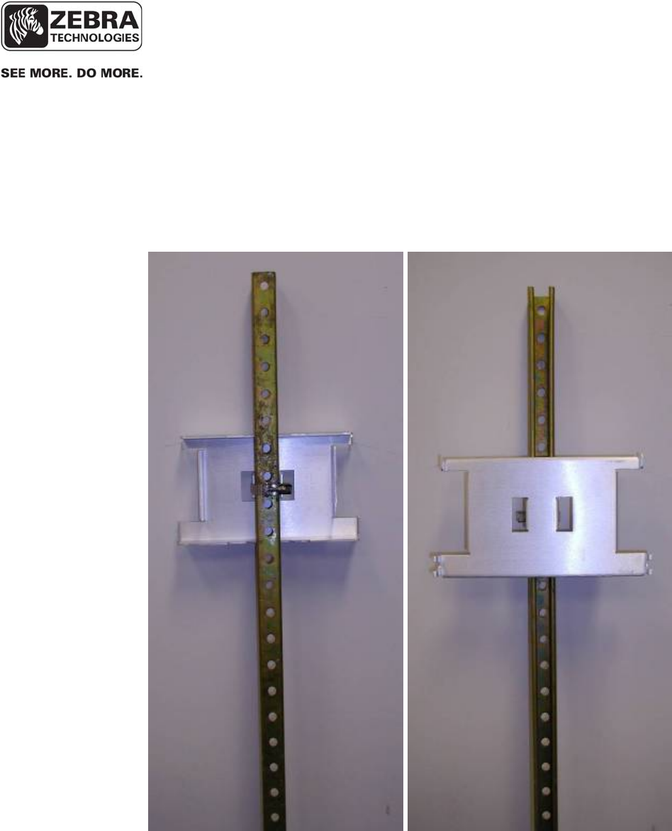
First mount bracket to metal frame in location, orientation and height
specified in the site design, with support hooks up and retaining slots down,
using supplied clamp.
Figure 9 Bracket Mount
6.4.1 Pole Mount on Metal Frame
___________________________________________________________________________
WhereLAN III User’s Guide
___________________________________________________________________________ 57
User’s Guide, WhereLAN III draft D1675 rev F
© Copyright Zebra Technologies, 2012
Zebra Confidential
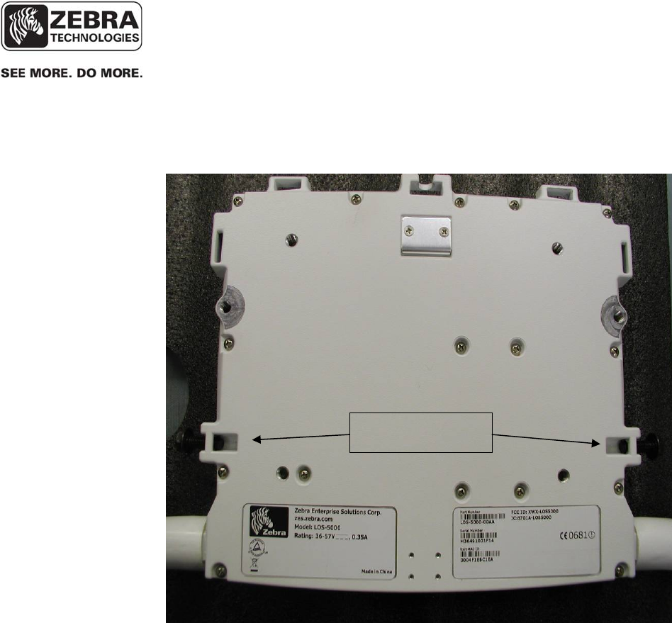
Loosen the retaining bolts on each side of the Location Sensor, but do not
remove them.
Figure 10 Retaining Bolts
Retaining Bolts
___________________________________________________________________________
WhereLAN III User’s Guide
___________________________________________________________________________ 58
User’s Guide, WhereLAN III draft D1675 rev F
© Copyright Zebra Technologies, 2012
Zebra Confidential
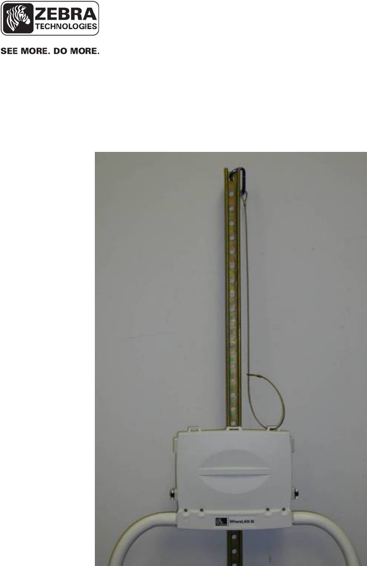
Hang the Location Sensor on the bracket and tighten retaining blots securely.
Next install safety lanyard through one of the Location Sensor’s lanyard
points, and the other end of the lanyard to a point above the Location Sensor.
Figure 11 Location Sensor Mounted
___________________________________________________________________________
WhereLAN III User’s Guide
___________________________________________________________________________ 59
User’s Guide, WhereLAN III draft D1675 rev F
© Copyright Zebra Technologies, 2012
Zebra Confidential
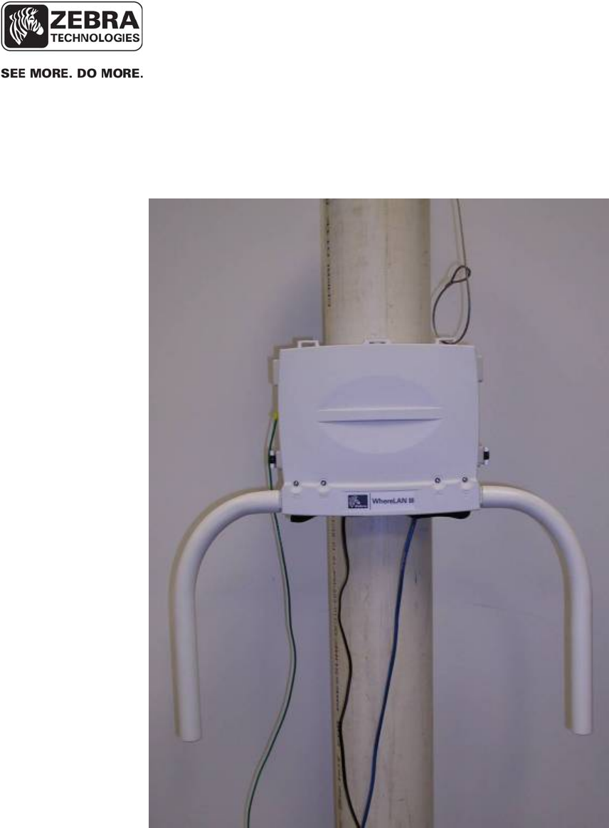
First mount bracket to Pole at height location, orientation and height specified
in the site design, with support hooks up and retaining slots down, using
supplied clamp.
Figure 12 Pole mount on Pole
Loosen the retaining bolts on each side of the Location Sensor, but do not
remove them (See Figure 10 Retaining Bolts).
6.4.2 Pole Mount on Pole
___________________________________________________________________________
WhereLAN III User’s Guide
___________________________________________________________________________ 60
User’s Guide, WhereLAN III draft D1675 rev F
© Copyright Zebra Technologies, 2012
Zebra Confidential
Hang the Location Sensor on the bracket and tighten retaining blots securely.
Next install safety lanyard through one of the Location Sensor’s lanyard
points, and the other end of the lanyard to a point above the Location Sensor.
Figure 13 Location Sensor on Pole
© Copyri
g
Zebra Co
n
___
__
U
s
g
ht Zebra Tech
n
n
fidential
7
T
w
a
n
th
in
be
F
i
_____________
_____________
s
er’s Guide,
W
n
ologies, 201
2
AN
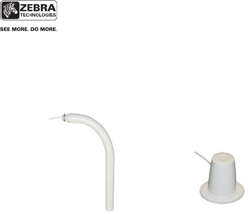
T
w
o different
n
tenna is the
e Location
S
doo
r
only i
n
e
specified i
n
i
gure 15 All
____________
Where
L
____________
W
hereLAN II
I
2
T
ENNAS
antennas ar
All Weathe
S
ensor hous
i
n
stallations
w
n
the site de
s
Weather O
m
_____________
L
AN III User’
s
_____________
I
e available
f
r Omni AK
-
i
ng. The O
ff
w
here appea
r
s
ign.
m
ni
____________
s
Guide
____________
f
or the Loca
t
-
210-10, wh
i
ff
ice Omni
A
r
ance critic
a
F
_____________
_____________
t
ion Sensor.
i
ch can be b
o
AK
-110-10 i
s
a
l. The choi
c
F
igure 14 O
f
____________
____________
draft D1675
The standa
r
o
lted directl
s
available f
o
c
e of antenn
a
f
fice Omni
_____
_____
61
rev F
r
d
y to
o
r
a
will
___________________________________________________________________________
WhereLAN III User’s Guide
___________________________________________________________________________ 62
User’s Guide, WhereLAN III draft D1675 rev F
© Copyright Zebra Technologies, 2012
Zebra Confidential
As its name suggests, the All Weather Omni provides omni-directional
coverage and is suitable for outdoor environments. It should be attached
directly to the Location Sensor housing, and therefore requires no additional
mounting. For this reason, it is the preferred antenna for the Location Sensor.
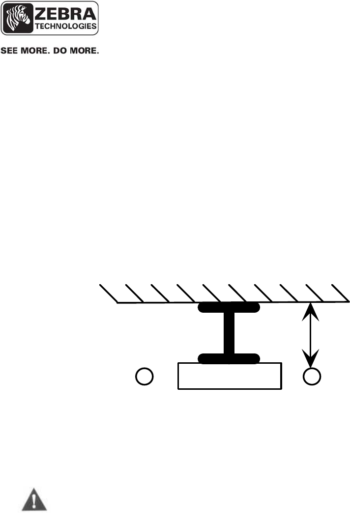
Because it is an omni-directional antenna, the coverage pattern of the All
Weather Omni can be degraded if mounted too close to metallic structures.
Therefore, the All Weather Omni must be mounted a minimum 12 inches (305
mm) from nearby metallic structures.
Figure 16 Minimum clearance to metallic structures
The All Weather (and Indoor Office) Omni antennas must be mounted a
minimum of 12 inches (305 mm) away from metal walls.
Min 12 inches
(305 mm) from
metal wall
I Beam
Right
antenna
Left
antenna
7.1.1 All Weather Omni
_____________
_____________
___________________________________________________________________________
WhereLAN III User’s Guide
___________________________________________________________________________ 63
User’s Guide, WhereLAN III draft D1675 rev F
© Copyright Zebra Technologies, 2012
Zebra Confidential
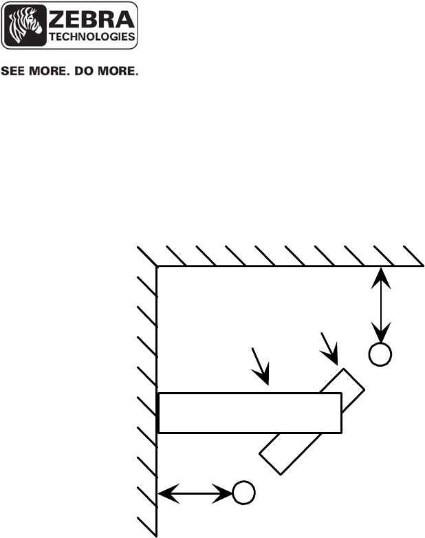
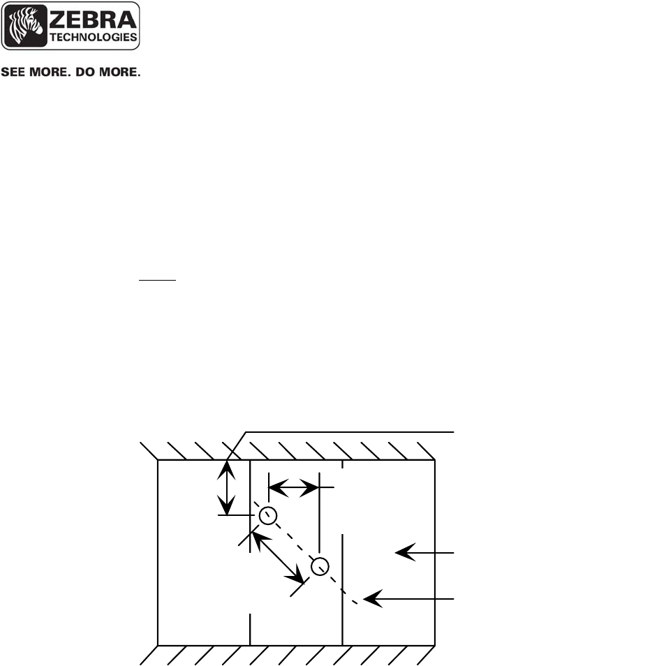
For best diversity reception, the Location Sensor should be mounted in an
orientation in which the antennas are at a diagonal (45 deg) orientation with
respect to surrounding walls and aisles. The RM-250 Wall Mount Bracket
can be utilized to provide the necessary clearance from nearby metallic
surfaces.
Figure 17 Corner mount industrial application
Min 12 inches
(305 mm) from
metal wall
Location
Sensor
Wall
Mount
Bracket Right
Antenna
Left
Antenna
___________________________________________________________________________
WhereLAN III User’s Guide
___________________________________________________________________________ 64
User’s Guide, WhereLAN III draft D1675 rev F
© Copyright Zebra Technologies, 2012
Zebra Confidential
The indoor omni is designed to be mounted directly to the ceiling. It has a
small profile designed to be unobtrusive in an office environment. Like the
All Weather Omni antenna, it must be mounted a minimum of 12 inches from
metal walls. There is no spacing requirement for drywall or other non-
metallic walls. For best diversity reception, mount the antennas in a diagonal
orientation 24 in (610 mm) from each other, in the center of the corridor (if
applicable), as shown in Figure 18 below. Be certain to note which antenna is
on the left, and which is on the right, and connect them to the appropriate
ports on the Location Sensor during installation.
Ceiling tile
Diagonal orientation
of antennas
M
i
n
i
m
u
m
12
i
n
(305 mm) clearance
to metal walls
17 in
(432 mm)
24 in
(610 mm)
Figure 18 Office omnidirectional in corridor
7.1.2 Indoor Omni

___________________________________________________________________________
WhereLAN III User’s Guide
___________________________________________________________________________ 65
User’s Guide, WhereLAN III draft D1675 rev F
© Copyright Zebra Technologies, 2012
Zebra Confidential
7.2 Vertical Diversity Mounting
Outdoor installations requiring the maximum location accuracy and
consistency should use vertical and horizontal diversity for antenna placement
should be implemented. This applies to most Yard and Marine Terminal
Sites. Zebra offers three different vertical diversity cable kits for installation.
For all installations, it is recommended that the Right antenna be higher than
the Left Antenna. Consult instruction sheet included in each kit and
WhereLAN III Installation Guide D1677 for further installation information.
1) Antenna Extension Cable Kit, CBL-010-10, which is a 5ft cable kit is
typically used for Yard Sites.
2) Antenna Extension Cable Kit, CBL-015-10 a 15ft. standard cable kit is
used for Marine Terminals.
3) Cable Kit CBL-015-11, Low Loss Antenna Extension, Location Sensor,
15ft may be used for Marine Terminals.
The most critical item in placing and installing the Location Sensors is to
ensure that the antennas are not blocked by nearby structures. Detailed
instructions with several examples are provided in the Location Sensor
Placement Guide D0406.
For accurate locate performance, the position of the left and right antennas
must be individually specified in the site design. System Builder requires the
center point and orientation of the antennas.
The left and right antenna must be correctly oriented per the site design.
Inadvertently reversing the left and right antennas results in a two foot
location error in standard diversity configurations and greater error in
vertical diversity configurations.
____________
____________
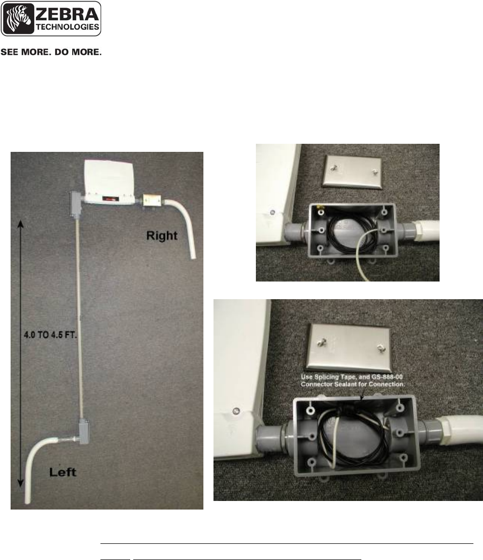
___________________________________________________________________________
WhereLAN III User’s Guide
___________________________________________________________________________ 66
User’s Guide, WhereLAN III draft D1675 rev F
© Copyright Zebra Technologies, 2012
Zebra Confidential
The following diagram is an example of how to achieve vertical diversity,
using 3/4” PCV schedule 40 conduit and ¾” PVC conduit fitting.
Carefully Coil excess cable for Right Channel.
Figure 19 Vertical Diversity 5ft,
*Use Splicing tape and ZES GS-888-00 connect sealant, install weather tight
cover. For Both Right and Left Antenna Connections.
7.2.1 Example Configuration Using CBL-010-10:
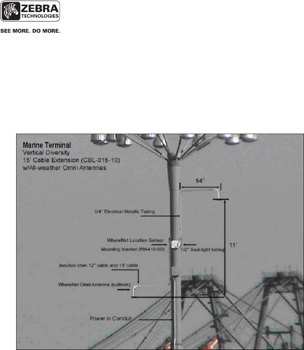
___________________________________________________________________________
WhereLAN III User’s Guide
___________________________________________________________________________ 67
User’s Guide, WhereLAN III draft D1675 rev F
© Copyright Zebra Technologies, 2012
Zebra Confidential
Below is a picture of a ZES Location Sensor installed on a 100’ light pole.
Note the Vertical Diversity (“VD”) created by extended antennas above and
below the Location Sensor. The installer will have to achieve at a minimum
the vertical distance of 11’ see below, the VD can be greater than 11’. This
installation calls for 12’ of diversity. The picture shows ¾” electrical
metallic tubing extending the “bullhorn” antennas (white).
Figure 20 Vertical Diversity +11ft.
7.2.2 Example Configuration Using CBL-015-10:
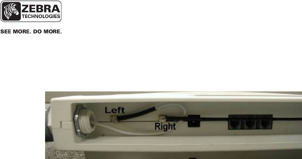
___________________________________________________________________________
WhereLAN III User’s Guide
___________________________________________________________________________ 68
User’s Guide, WhereLAN III draft D1675 rev F
© Copyright Zebra Technologies, 2012
Zebra Confidential
Make appropriate connection to the Location Sensor, as shown below.
Figure 21 Vertical Diversity Connections
7.3 Wi-Fi 802.11 b/g Antennas
There are three antenna options for Wi-Fi network connectivity of the for the
LOS-5000-01AB.In addition, the CBK-020-00 allows you to connect to the
smb Wi-Fi port aon the unit and must always be separately procured. See
instruction sheet included with cable mounting bracket kit regarding
installation. See Site Design for specifics of WLAN antenna choice and
orientation.
• Wi-Fi Antenna Indoor 2.2dBi
• Wi-Fi Antenna Outdoor Omni
5.2dBi
• Wi-Fi Antenna Outdoor
Directional 13.5dBi
AK-170-00
AK-151-00
AK-153-00
7.2.3 Vertical Diversity Connections
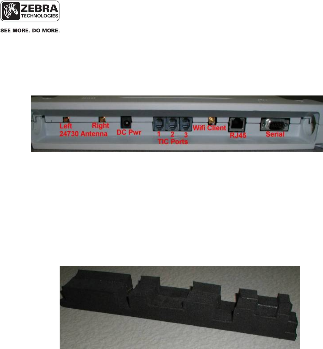
___________________________________________________________________________
WhereLAN III User’s Guide
___________________________________________________________________________ 69
User’s Guide, WhereLAN III draft D1675 rev F
© Copyright Zebra Technologies, 2012
Zebra Confidential
8 CABLING
The figure below, labels the appropriate connections which must be made to
the Location Sensor in normal operation. The connector types and
recommended cable types are detailed in Section 3.
Figure 22 Location Sensor Connections
For all Outdoor installations:
• Use part GS-888-00 grease (supplied with unit) in ALL Connecter
Jacks. Fill each of the following connections, with Nyogel Weather
Sealant, these include the Left and Right antenna, Timing connections,
Wi-Fi Client, Ethernet, Serial interface, and Power connection. This is
to help weather proof the connections from water and corrosion.
• Routing the cables through the Drip Plug, supplied with unit, plug
cables into units and fully (carefully) fully install Drip Plug into
connector well.
Figure 23 Drip Plug

___________________________________________________________________________
WhereLAN III User’s Guide
___________________________________________________________________________ 70
User’s Guide, WhereLAN III draft D1675 rev F
© Copyright Zebra Technologies, 2012
Zebra Confidential
8.1 Power, AC
The WhereLAN III location sensor can be powered via IEEE 802.3af POE or
directly with a standalone DC power supply.
If the standalone DC power supply is option is used, the customer must
provide 100-240 VAC 50/60 Hz power to the specified Location Sensor
position. The Location Sensor units require DC 36-57V, 250mA for operation
(12 Watts). The recommended power supply (PS-040-00), which must be
purchased separately, has a 6 ft (2 m) AC cable and a 6 ft (2 m) dc cable. For
longer cabling runs, the recommended power supply is the PS-045-00. The
electrician should verify that the AC power is available within 2 m of the
position of the power supply. The Location Sensor itself may be installed up
to 20 m and 100 m from the PS-040-00 and PS-045-00 power supplies,
respectively. . This allows a 6 ft (2 m) “service loop” margin if the Location
Sensor position must be readjusted after the AC power is installed.
The WhereLAN III must always be used with the specified power supply.
The use of a different power supply could result in equipment damage
and/or electric shock or fire hazard.
Two optional 50 ft (15 m) dc power extension cables are available for
installations in which it is not desirable to rout the AC power within 6 ft (2 m)
of the WhereLAN III. One is for indoor use only and is Plenum Rated, ZES
Part Number PX-010-00. The other is an outdoor rated (UV stable), ZES
Part Number PX-050-00. Consult your ZES Account Manager for
recommended wire size if additional lengths are required for a particular
installation.
Power Supplies have a limited safe operating temperature rating, please
check with the account representative concerning limitations or
availability of extend temperature range power supply, such as PS-040-
00. In outdoor installations the power supply must be installed within a
suitable waterproof housing per applicable building codes. The use of a
non qualified housing could result in equipment damage and/or electric
shock or fire hazard.
_____________
_____________
_____________
_____________
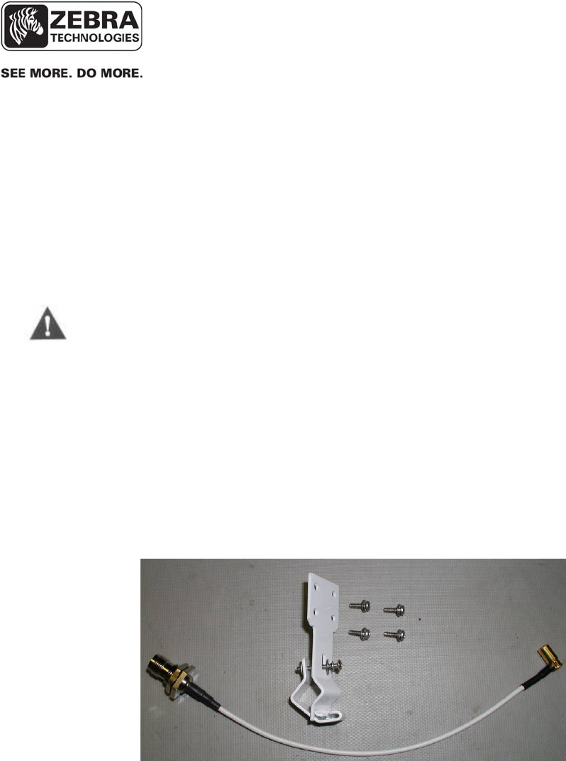
___________________________________________________________________________
WhereLAN III User’s Guide
___________________________________________________________________________ 71
User’s Guide, WhereLAN III draft D1675 rev F
© Copyright Zebra Technologies, 2012
Zebra Confidential
8.1 Ethernet
The WhereLAN III utilizes standard 10/100 802.3 Ethernet connectivity via
cat 5 cables. The Location Sensor must be wired to a nearby hub, which is in
turn connected to the network containing the database CPU. The maximum
Ethernet cable run is 328 ft (100 m). If additional distance is required, hubs,
repeaters, and fiber (with 10/100BaseT converters) can be used to extend the
distance. Refer to IEEE guidelines for Ethernet cabling.
Do not exceed the maximum Ethernet cabling length of 328 ft (100 m).
8.2 Wi-Fi Antenna Kit
The LOS-5000-00AB WhereLAN-III with Wi-Fi has the option of adding on
an antenna cable and mounting bracket kit CBK-020-00. This kit is intended
to work with any of the three Wi-Fi antenna Accessories.
The kit consist of the mounting bracket, 4 screws, and the SMB to RP-TNC
cable.
Figure 24 CBK-020-00
____________
____________
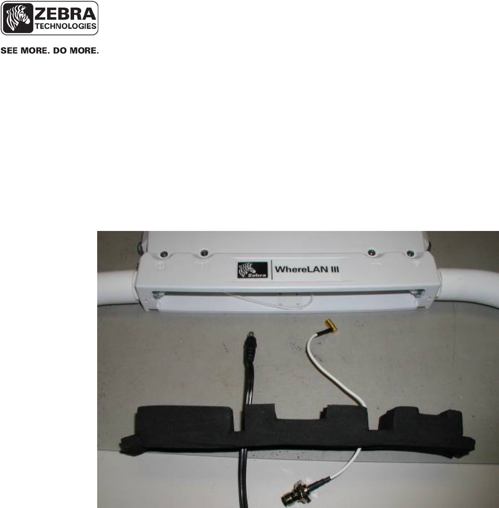
___________________________________________________________________________
WhereLAN III User’s Guide
___________________________________________________________________________ 72
User’s Guide, WhereLAN III draft D1675 rev F
© Copyright Zebra Technologies, 2012
Zebra Confidential
The following steps will outline the installation of the CBK-020-00 Wi-Fi
Bracket and Cable Kit.
1. Run required cables through the Drip Plug, matching up the cutouts
with the appropriate connector location.
Figure 25 Wi-Fi Cable 1
8.2.1 Wi-Fi Kit Installation
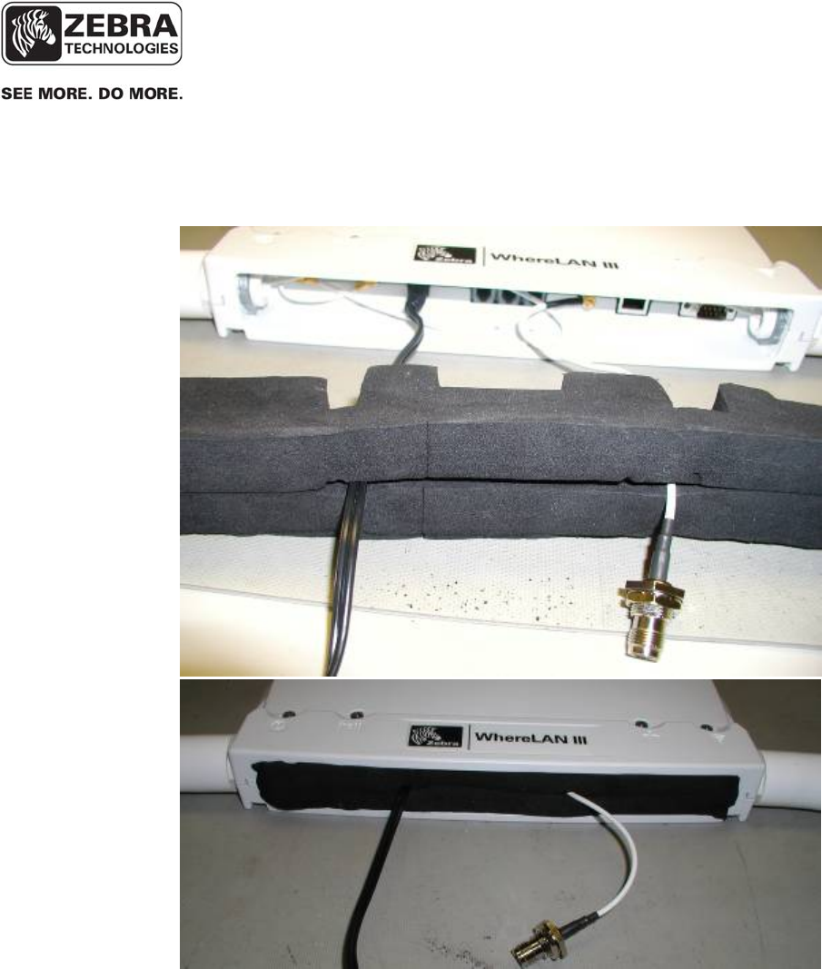
___________________________________________________________________________
WhereLAN III User’s Guide
___________________________________________________________________________ 73
User’s Guide, WhereLAN III draft D1675 rev F
© Copyright Zebra Technologies, 2012
Zebra Confidential
2. Next connect the cables to the WhereLAN-III, and install Drip Plug by
carefully pressing Drip Plug into connector well without pinching the
cables.
Figure 26 Wi-Fi Cables Drip Plug
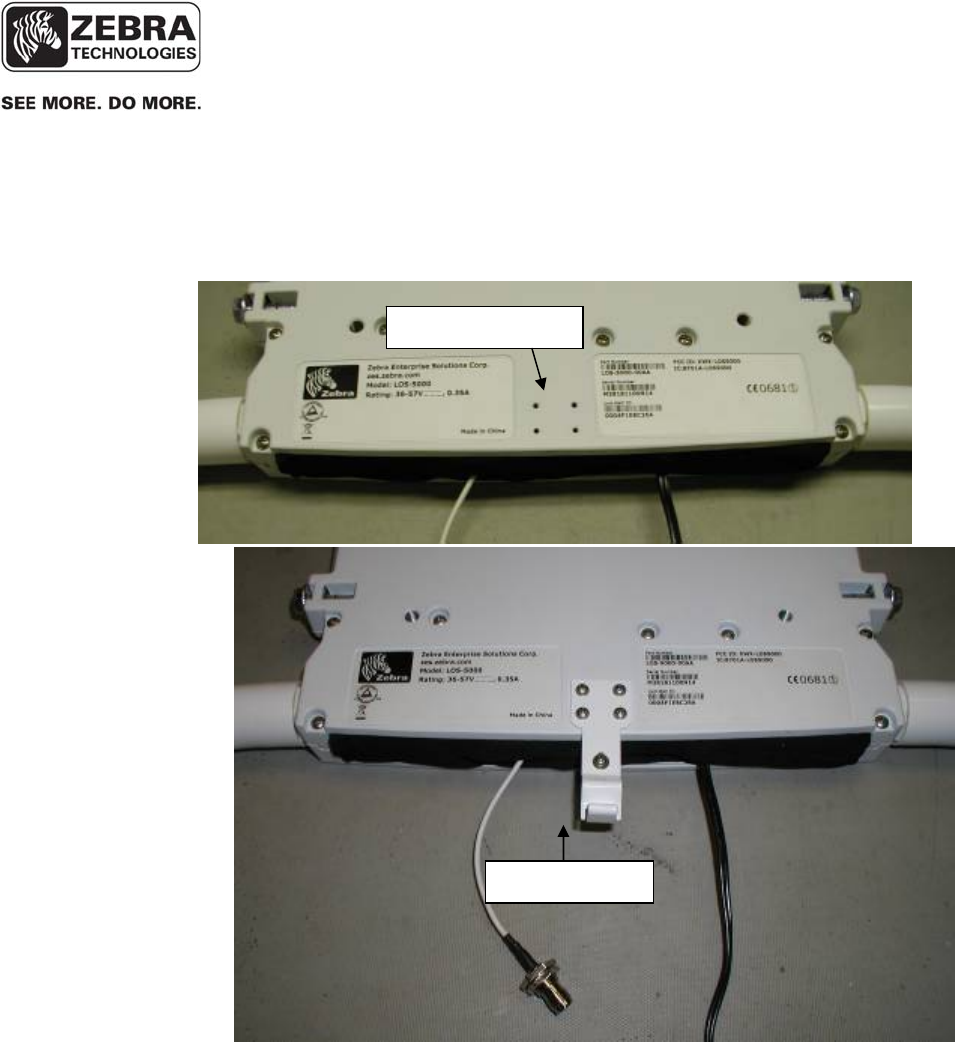
___________________________________________________________________________
WhereLAN III User’s Guide
___________________________________________________________________________ 74
User’s Guide, WhereLAN III draft D1675 rev F
© Copyright Zebra Technologies, 2012
Zebra Confidential
3. Now install the Wi-Fi cable bracket on the rear side of the unit, as
shown below, using the supplied hardware. The hinged portion of the
clamp should be facing the front of the unit. Recommended torque for
mounting screws is 6 in-lbs (0.68Nm).
Figure 27 Wi-Fi Bracket
Mountin
g
Holes
Wi-Fi
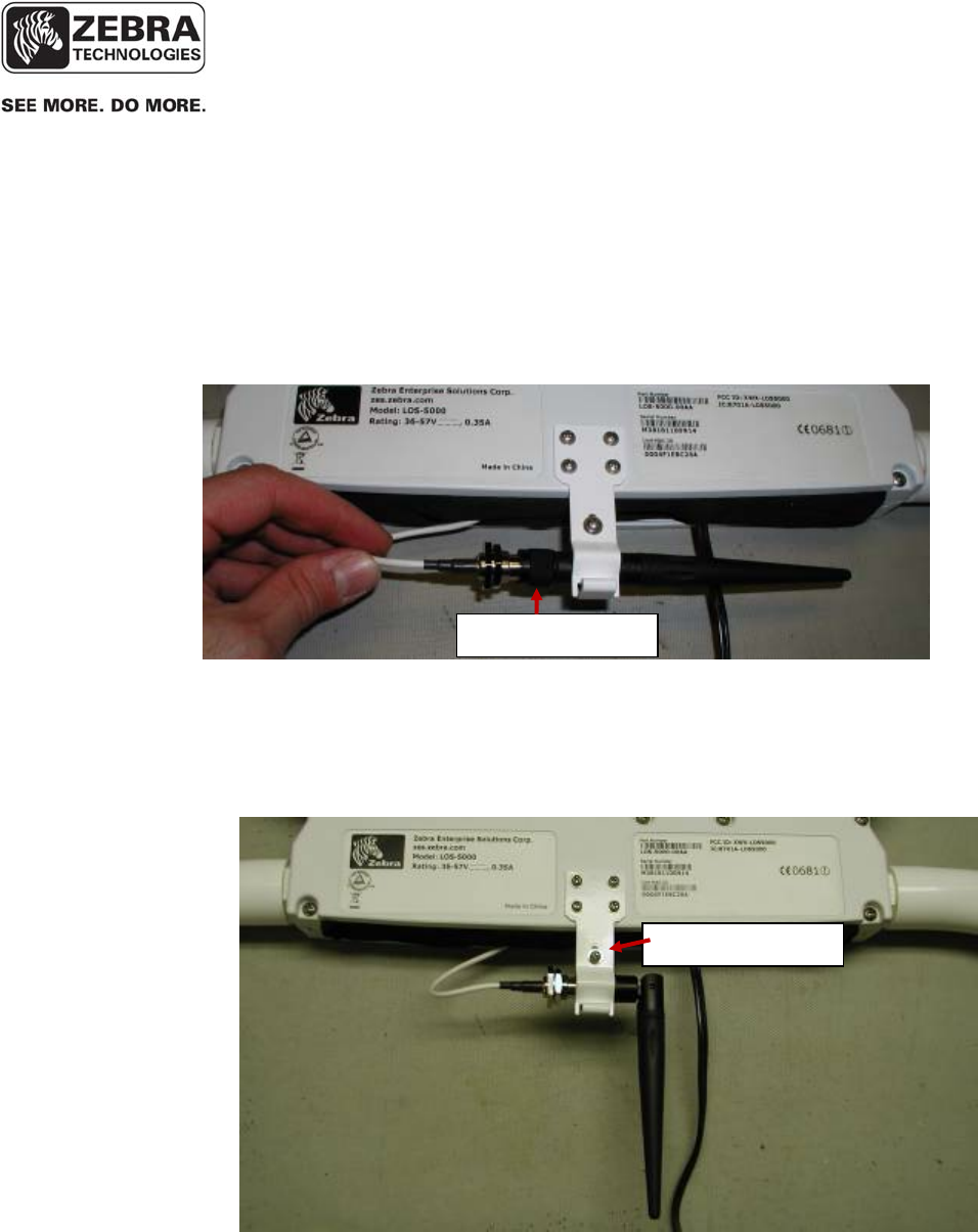
___________________________________________________________________________
WhereLAN III User’s Guide
___________________________________________________________________________ 75
User’s Guide, WhereLAN III draft D1675 rev F
© Copyright Zebra Technologies, 2012
Zebra Confidential
4. Installing the Wi-Fi antenna.
a. Option 1 for the AK-170-00 2.2dBi Dipole Antenna (Rubber
Duck Style). Slide the antenna, with the antenna straight,
through the Wi-Fi bracket and tighten onto the RP-TNC
connector. Recommend 12 to 15 in-lbs of torque (1.4 to 1.7
Nm).
Figure 28 2.2 dBi Dipole
Then slip the knurled part of the antenna connector back into the Wi-Fi
Bracket clamp, and tighten the retaining screw to 2 in-lbs (0.23Nm).
Then articulate the antenna downward.
Figure 29 2.2 dBi Installed.
Knurled Sectio
n
Retainin
g
Screw
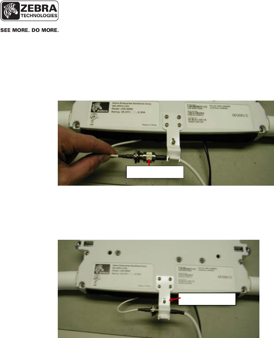
___________________________________________________________________________
WhereLAN III User’s Guide
___________________________________________________________________________ 76
User’s Guide, WhereLAN III draft D1675 rev F
© Copyright Zebra Technologies, 2012
Zebra Confidential
b. Option 2 is for either the AK-151-00 Cisco 5.2dBi Omni or the
AK-153-00 Cisco 13.5 dBi Yagi antenna. These are both
remotely mounted antenna. Slide the antenna connector
through the Wi-Fi Bracket Clamp and tighten onto the RP-
TNC connector. Recommend 12 to 15 in-lbs of torque (1.4 to
1.7 Nm).
Figure 30 Wi-Fi Bracket Remote Antenna
Then slip the knurled part of the antenna connector back into the Wi-Fi
Bracket clamp, and tighten the retaining screw to 2 in-lbs (0.23Nm).
Mount the antenna according to the recommend instructions provided
with the antenna and in the site design document.
Figure 31 Remote Antenna Clamp
Note: For all outdoor installations use the connector grease supplied with
the unit for this connection.
Knurled Sectio
n
Retainin
g
Screw

___________________________________________________________________________
WhereLAN III User’s Guide
___________________________________________________________________________ 77
User’s Guide, WhereLAN III draft D1675 rev F
© Copyright Zebra Technologies, 2012
Zebra Confidential
8.3 Timing Cable Interconnection Guidelines
In certain cases, the WhereLAN III may require a timing cable to be
connected to other nearby WhereLAN III units. In general, the use such wired
timing links should not be necessary with a good site design, but may be
necessary in select cases. The site design document, provided by the site
designer, will specify which Location Sensors will be connected together.
Each of the three timing ports on the Location Sensor is an identical bi-
directional link. The cable and connector types are specified in section 4
above.
The following rules must be applied when connecting timing cables between
the Location Sensors:
• Do not connect the timing cable from one Location Sensor back to the
same Location Sensor.
• Do not connect two timing cables between the same two Location
Sensors.
• The maximum timing cable length is 1000 feet (305 m).
Do not exceed the maximum timing cabling length of 1000 ft (305 m).
Install the Location Sensor timing cables from one unit to the next, as
specified in the site design document, using the specified 2 pair or 4 pair*
cable and RJ22 (telephone handset 4c4p) connectors. (* see 8.2.1). Incorrect
routing of the timing cables between the Location Sensors may result in
decreased location accuracy.
____________
Note
____________
____________
Note
____________
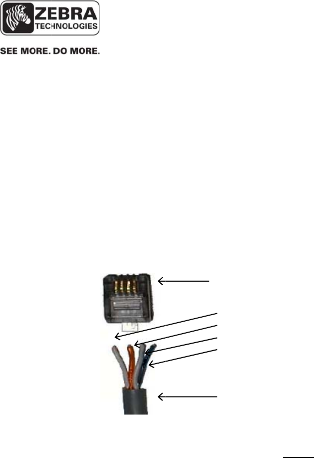
© Copyri
g
Zebra Co
n
______
Note
______
___
__
U
s
g
ht Zebra Tech
n
n
fidential
T
h
w
i
c
a
I
n
C
a
P
a
P
a
F
i
F
o
s
e
p
a
a
v
i
n
8.
3
_______
_______
_____________
_____________
s
er’s Guide,
W
n
ologies, 201
2
h
is Cat5 tw
o
i
th pin 1 on
a
ble, the foll
o
n
stallation G
u
a
bles.
a
ir 1: orang
e
a
ir 2: white/
b
i
gure 32 Ti
m
o
r a reliabl
e
e
curel
y
cri
m
a
ir cable be
v
ailable Sta
n
n
Installatio
n
3
.1 Timi
n
____________
Where
L
____________
W
hereLAN II
I
2
o
pair cable
s
one end rou
t
o
wing pin o
u
u
ide D1677
e
/white wire
b
lue wire is
p
m
ing cable
w
e
s
y
stem op
e
m
ped inside
t
utilized to
e
n
dard ei
g
h
t
n
Guide D1
ng
Cable
P
R
T
T
T
T
_____________
L
AN III User’
s
_____________
I
s
hould be c
o
t
ed to pin 1
o
u
t must be
u
for full inst
a
is pin 1; or
a
p
in 3; blue
w
w
iring pin o
u
e
ration, the
t
he RJ-22 (
4
e
nsure a pr
t
conductor
677 must b
e
P
in-Out
R
J22
2 Pair Cat5
T
o pin 1 wh
i
T
o Pin 2 or
a
T
o pin 3 wh
i
T
o pin 4 blu
____________
s
Guide
____________
o
nstructed w
i
o
n the other
u
sed (Figure
a
ll details, a
n
a
nge wire is
p
w
ire is pin 4
u
t
jacket of t
h
4
p4c) conn
e
oper crimp
Cat 5 cabl
e
e
followed.
i
te/orange
a
nge
i
te/blue
e
_____________
_____________
i
th straight t
h
end. For t
h
3212). See
W
n
d use of C
A
p
in 2
h
e timin
g
c
a
e
ctor. It is
r
. If a 2 pair
e
ma
y
be us
e
____________
____________
draft D1675
h
rough wiri
n
h
e 2 pair C
A
W
hereLAN
A
T-5 for Ti
m
a
ble must b
e
r
ecommend
e
cable is no
t
e
d, but the
_____
_____
78
rev F
n
g,
A
T5
III
m
ing
e
e
d 2
t
steps
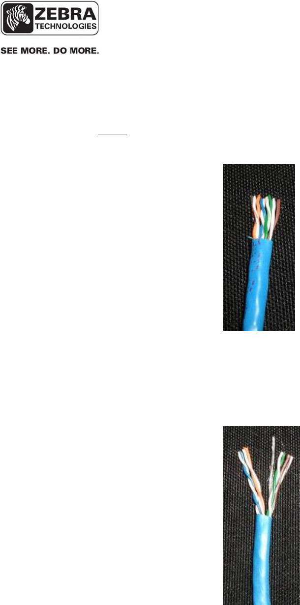
___________________________________________________________________________
WhereLAN III User’s Guide
___________________________________________________________________________ 79
User’s Guide, WhereLAN III draft D1675 rev F
© Copyright Zebra Technologies, 2012
Zebra Confidential
Steps:
1. Trim out Jack back approximately ½ inch.
Figure 33 Timing Cable Trim
2. Pull Back Jack until at least 1-1/4 inches of wire is exposed, separate
Blue/White and Orange/White pair from Green/White and Brown/White
pair.
Figure 34 Timing Cable Jacket
8.3.2 Cat-5 Four Pair Installation
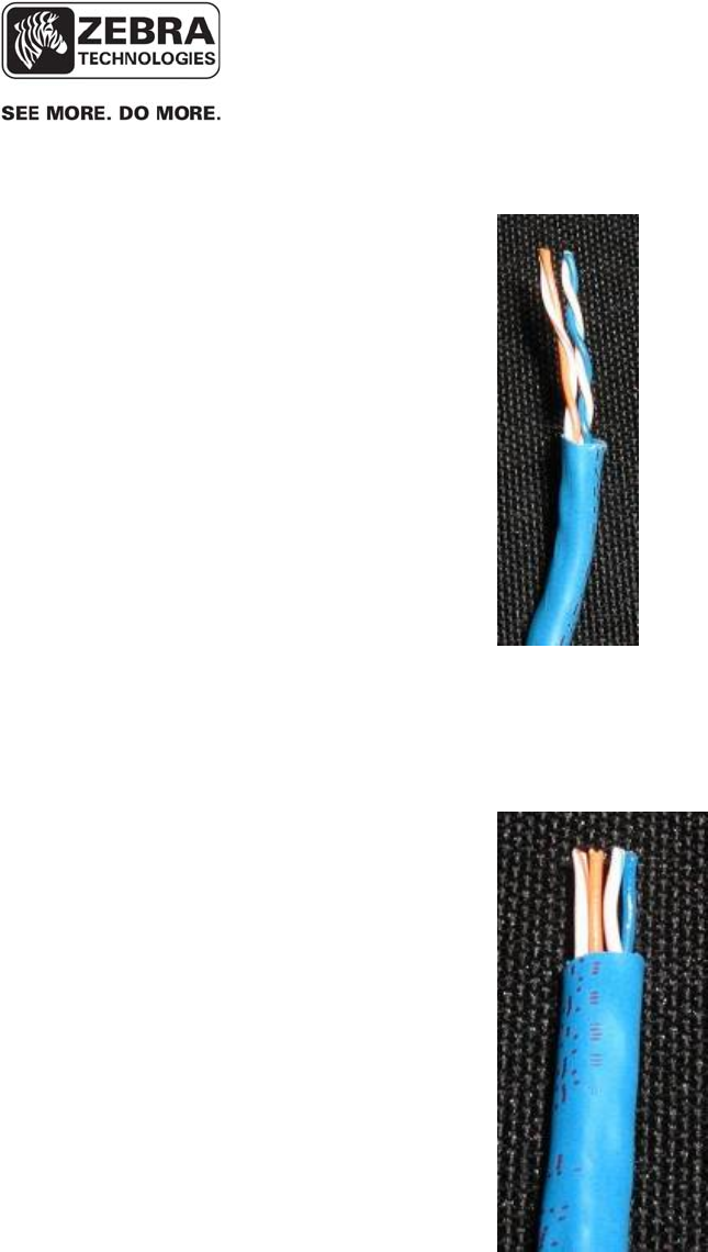
___________________________________________________________________________
WhereLAN III User’s Guide
___________________________________________________________________________ 80
User’s Guide, WhereLAN III draft D1675 rev F
© Copyright Zebra Technologies, 2012
Zebra Confidential
3. Trim the Green/White and Brown/White Pairs flush with outer jacket.
Figure 35 Timing Cable Trim
4. Pull outer jacket back up leaving only ¼ inch of wire exposed. Separate
wires as shown in Figure 21 and trim wires evenly.
Figure 36 Timing Cable Pull Jacket
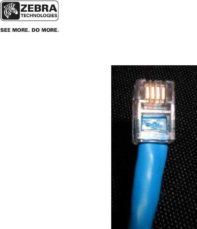
___________________________________________________________________________
WhereLAN III User’s Guide
___________________________________________________________________________ 81
User’s Guide, WhereLAN III draft D1675 rev F
© Copyright Zebra Technologies, 2012
Zebra Confidential
5. Insert into RJ-22(4p4c) as shown and crimp with appropriate tool. Note
outer cable jacket is captured by strain relief.
Figure 37 Timing Cable Crimp
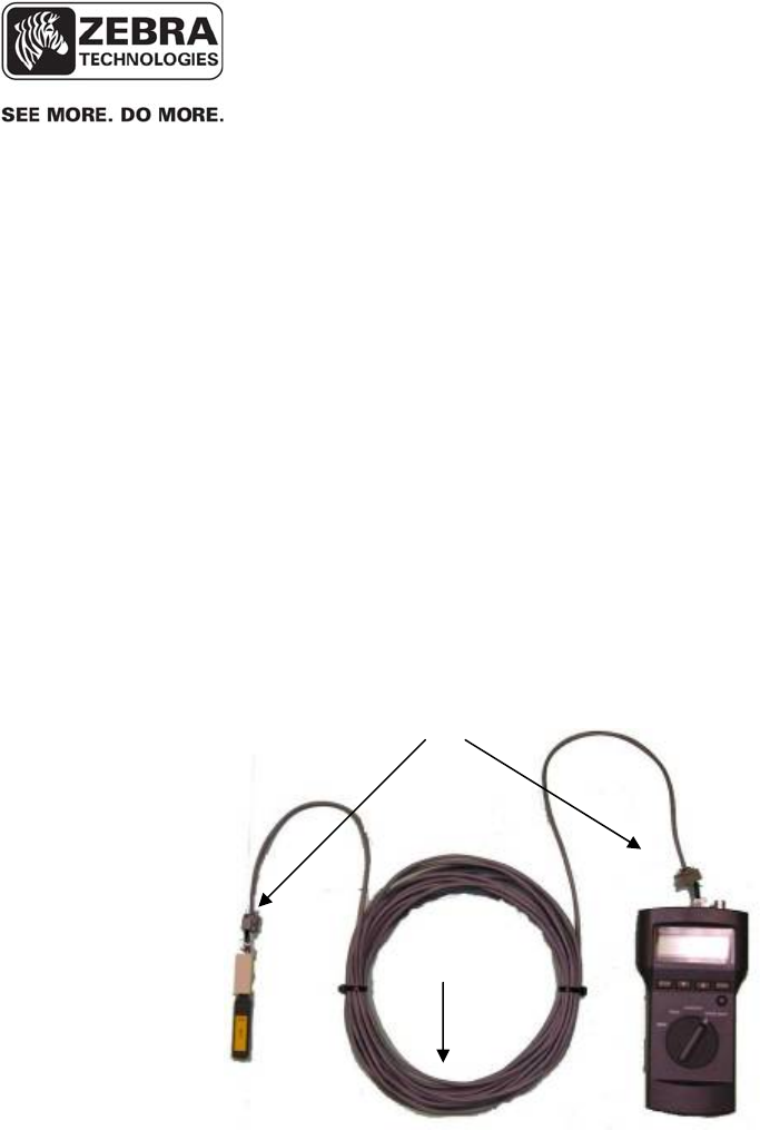
___________________________________________________________________________
WhereLAN III User’s Guide
___________________________________________________________________________ 82
User’s Guide, WhereLAN III draft D1675 rev F
© Copyright Zebra Technologies, 2012
Zebra Confidential
The timing cables must be properly wired in order for the timing signal to be
transmitted from one Location Sensor to the other. It is recommended that
this test be completed on each cable by the installer prior to operation. This
test requires quantity 2 four pair to two pair connector adapters ZES p/n
21204, and a Fluke 620 CableMeter. Brief instructions are provided below;
consult the Fluke CableMeter instruction manual for detailed instructions.
Setup
Connect adapter #1 between the Fluke 620 CableMeter and the near end of the
cable to be tested. Connect the Fluke Cable ID unit and adapter #2 to the far
end of the cable to be tested using a RJ-45 coupler.
Figure 38 Test setup for CAT5 cable using Fluke 620
8.3.3 Timing Cable Test Procedure
2 pair adapters
Cable
under test

___________________________________________________________________________
WhereLAN III User’s Guide
___________________________________________________________________________ 83
User’s Guide, WhereLAN III draft D1675 rev F
© Copyright Zebra Technologies, 2012
Zebra Confidential
Procedure
Use the SETUP to select cable type, wire standard, category and wire size on
the Fluke CableMeter:
• Cable: UTR
• Wiring: 10BaseT 2PR
• Category: Cat5
• Wire Size: AWG24
Turn the Fluke CableMeter rotary switch to WIRE MAP. The correct readout
when testing 2 pair cable is shown in Figure 39 below. If a different readout
appears, the cable was not constructed properly and must be corrected.
Figure 39 Correct readout when testing 2 pair cable.
12 36 ID
12 36 #1
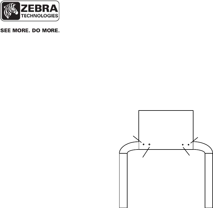
___________________________________________________________________________
WhereLAN III User’s Guide
___________________________________________________________________________ 84
User’s Guide, WhereLAN III draft D1675 rev F
© Copyright Zebra Technologies, 2012
Zebra Confidential
8.4 Location Sensor Operational Verification
Prior to optimizing locate performance, the operation of the Location Sensor
must be verified. The checklist below specifies the verification of the
configuration and basic operation.
Figure 40 Location Sensor LED indicators
Verify that each Location Sensor is operational by verifying that the
left Power/ Health LED is illuminated solid red.
For wired 802.3 Location Sensors, verify that the Ethernet LED is
solid red when connected and blinking red when activity is present.
Verify that the RX detects LED is blinking red indicating reception of
tag blinks.
For wireless LOS-5000-00AB Location Sensors, verify that the
WLAN activity LED is blinking red during power up state and solid
red otherwise.
Confirm that the site Location Sensor channel assignment is correct by
running “display locate” from the Blink Console under the Blink
Service Diag window, with a tag placed directly under each LS.
Verify that the nearest Location Sensor, as indicated by a “0” in the
display locate report, is that Location Sensor nearest the tag.
Location Sensor
Outdoor
Omni
Antenna
P
ower/
H
ealth
Tag
Reception Ethernet
WLAN

___________________________________________________________________________
WhereLAN III User’s Guide
___________________________________________________________________________ 85
User’s Guide, WhereLAN III draft D1675 rev F
© Copyright Zebra Technologies, 2012
Zebra Confidential
Verify that detects are received by the Location Sensor using Blink
Consoles when, a tag is placed at a distance from each Location
Antenna equivalent to the maximum required range from that Location
Antenna. Typical tag to Location Antenna range is 1000 ft (305 m)
(Unobstructed/ outdoor), 350 ft (107 m) Minimally Obstructed (indoor
office/ light commercial), 250 feet (76 m) Significantly Obstructed
(heavy industrial).
Section Signoff
Initial Date Comments/ Exceptions
Note See Blink Console User’s Guide.

___________________________________________________________________________
WhereLAN III User’s Guide
___________________________________________________________________________ 86
User’s Guide, WhereLAN III draft D1675 rev F
© Copyright Zebra Technologies, 2012
Zebra Confidential
REGULATORY INFORMATION
FCC Regulatory Compliance Information
This device complies with FCC Part 15.247.
Operation is subject to the following two conditions:
(1) This device may not cause harmful interference
(2) This device must accept any interference which may cause undesired operation
This equipment has been tested and found to comply with the limits for a Class A
digital device, pursuant to part 15 of the FCC Rules. These limits are designed to
provide reasonable protection against harmful interference when the equipment is
operated in a commercial environment. This equipment generates, uses, and can radiate
radio frequency energy and, if not installed and used in accordance with the instruction
manual, may cause harmful interference to radio communications. Operation of this
equipment in a residential area is likely to cause harmful interference in which case the
user will be required to correct the interference at his own expense.
RF Notice
Any changes or modifications to equipment not expressly approved by Zebra
Technologies Corporation could void the user’s authority to operate the equipment.
FCC Radiation Exposure Statement
This equipment complies with FCC radiation exposure limits set forth for an
uncontrolled environment. This equipment should be installed and operated with
minimum distance 20cm between the radiator and your body. This transmitter must not
be co-located or operating in conjunction with any other antenna or transmitter.
Industry Canada Compliance Statements
Operation is subject to the following two conditions: (1) this device may not cause
interference, and (2) this device must accept any interference, including interference
that may cause undesired operation of the device.
Le présent appareil est conforme aux CNR d'Industrie Canada applicables aux appareils
radio exempts de licence. L'exploitation est autorisée aux deux conditions suivantes :
(1) l'appareil nedoit pas produire de brouillage, et (2) l'utilisateur de l'appareil doit
accepter tout brouillage radioélectrique subi, même si le brouillage est susceptible d'en
compromettre le fonctionnement.

___________________________________________________________________________
WhereLAN III User’s Guide
___________________________________________________________________________ 87
User’s Guide, WhereLAN III draft D1675 rev F
© Copyright Zebra Technologies, 2012
Zebra Confidential
This Class A digital apparatus complies with Canadian ICES-003.
Cet appareil numérique de la classe A est conforme à la norme NMB-003 du Canada.
This device and its antenna(s) must not be co-located or operating in conjunction with
any other antenna or transmitter.
Cet appareil et son antenne (s) ne doit pas être co-localisés ou fonctionnant en
conjonction avec une autre antenne ou transmetteur.
This equipment should be installed and operated with a minimum distance of 20cm
between the radiator and your body
Cet équipement doit être installé et utilisé à une distance minimale de 20cm entre le
radiateur et votre corps.
It is the responsibility of the installer to ensure that when using the outdoor antenna
kits, only those antennas certified with the product are used. The use of any antenna
other than those certified with the product is expressly forbidden by FCC rules 47 CFR
part 15.204 and IC RSS standards.
Il est de la responsabilité de l'installateur de s'assurer que lorsque vous utilisez les kits
d'antennes extérieures, seules les antennes certifiés avec le produit sont utilisés.
L'utilisation d'une antenne autre que ceux qui sont certifiés avec le produit est
expressément interdite par la réglementation FCC partie 47 CFR 15.204 et IC normes
RSS.

___________________________________________________________________________
WhereLAN III User’s Guide
___________________________________________________________________________ 88
User’s Guide, WhereLAN III draft D1675 rev F
© Copyright Zebra Technologies, 2012
Zebra Confidential
EU & EFTA Compliance Information
Approved for use in the following countries.
AT BE BG CY CZ DK EE
FI FR DE GR HU IE IT
LV LT LU MT NL PL PT
RO SK SI ES SE GB
IS LI NO CH TR

___________________________________________________________________________
WhereLAN III User’s Guide
___________________________________________________________________________ 89
User’s Guide, WhereLAN III draft D1675 rev F
© Copyright Zebra Technologies, 2012
Zebra Confidential
APPENDIX A: LOS-5000 EFFECTIVE PROJECTED
AREA (EPA)
LOS Housing
• Housing Size (Inches) [cm]: 12.0” [30.4] Wide, 10.3” High [26.2], 1.7” [4.3] Deep
• Housing Size with 1/2" Radial Ice (Inches) [cm]: 12.5” [31.8] Wide, 10.8” High [27.4], 2.3” [5.8]
Deep
• Maximum Projected Area with Ice (Square Inches): 135.0” [2212 cc]
• Shape Factor (CD per EIA-222-F) 1.4
• Effective Projected Area with Ice (Square Inches) 189 [3097cc]
Omni Antenna (One Antenna)
• Antenna Size (Inches) [cm]: 1.3 [3.3] Diameter 19.0 [302] Long
• Antenna Size with 1/2" Radial Ice (Inches): 2.3 [5.8] Diameter 20.0 [50.8] Long
• Maximum Projected Area with Ice (Square Inches): 46.6 [763cc]
• Shape Factor (CD per EIA-222-F) 0.8
• Effective Projected Area with Ice (Square Inches) 37.3 [611cc]
LOS-5000 Effective Projected Area (EPA)
• LOS Housing with Ice (Inches): 189 [3097cc]
• Omni Antenna #1 with Ice (Inches): 37.3 [611cc]
• Omni Antenna #2 with Ice (Inches): 37.3 [611cc]
• Total Effective Projected Area with 0.5 inch Radial Ice
Effective Projected Area, Total (Square Inches): 263.6 [4319cc]
Note: The above does not include conduit/cabling for Omni Antenna polarization diversity and
LOS-5000 power

___________________________________________________________________________
WhereLAN III User’s Guide
___________________________________________________________________________ 90
User’s Guide, WhereLAN III draft D1675 rev F
© Copyright Zebra Technologies, 2012
Zebra Confidential
APPENDIX B: LOS-5000 WEIGHT
LOS-5000 Housing
• Housing Weight (Pounds): 7.0 [3.17.0Kg]
• Ice Volume at 0.5 inch [12.7mm] Radial Thickness: 94.7 Cubic Inches [1552cc]
• Assumed density of Ice: 0.032 pounds per cubic inch [0.90 g/cc]
• Mass of Ice: 3.0 pounds [1.4Kg]
• Housing and Ice Mass: 10.0 pounds [4.53Kg]
Omni Antenna (One Antenna)
• Antenna Weight: 0.8 pounds [0.36Kg]
• Ice Volume at 0.5 inch [12.7mm] Radial Thickness: 58.9 Cubic inches [965 cc]
• Assumed density of Ice: 0.032 pounds per cubic inch [0.90 g/cc]
• Ice Weight: 1.9 pounds [.86Kg]
• Antenna and Ice Weight: 2.7 pounds [1.22Kg)
Total Weight with 1/2" Radial Ice
• LOS Housing Ice: 10.0 pounds [4.53Kg]
• Omni Antenna #1 with Ice: 2.7 pounds [1.22Kg]
• Omni Antenna #1 with Ice: 2.7 pounds [1.22Kg]
Weight, Total: 15.4 pounds [6.98Kg]
Note: The above does not include conduit/cabling for Omni Antenna polarization diversity and
LOS-5000 power

___________________________________________________________________________
WhereLAN III User’s Guide
___________________________________________________________________________ 91
User’s Guide, WhereLAN III draft D1675 rev F
© Copyright Zebra Technologies, 2012
Zebra Confidential
APPENDIX C: WI-FI REGULATORY
COMPLIANCE
TBD

___________________________________________________________________________
WhereLAN III User’s Guide
___________________________________________________________________________ 92
User’s Guide, WhereLAN III draft D1675 rev F
© Copyright Zebra Technologies, 2012
Zebra Confidential
Antenna options
This mini PCI card has been tested and found to be in compliance when used with the following
2.4 GHz antennas:
Cisco Aironet 5.2-dBi Dipole Omnidirectional Antenna (P/N AIR-ANT2506)
Cisco Aironet 2-dBi Dipole Omnidirectional Antenna (P/N AIR-ANT4941)
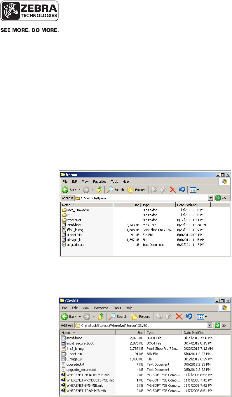
___________________________________________________________________________
WhereLAN III User’s Guide
___________________________________________________________________________ 93
User’s Guide, WhereLAN III draft D1675 rev F
© Copyright Zebra Technologies, 2012
Zebra Confidential
APPENDIX D: FIRMWARE UPGRADE
The WhereLAN-III’s firmware can be upgraded manually without the use of
iSensor or similar tool set. The upgrade can take place through the Menu
system on the WhereLAN-III, and a network connection supporting either
FTP or TFTP must be present. The following examples are done using an SSH
connection. However any of the way to get to the WhereLAN-III Menu
system is valid. All the same generation location sensors on site must have
same Firmware Build Date. (All WhereLAN-III’s must have same WhereLAN-
III firmware and all WhereLAN-2’s must have same WhereLAN-2 firmware).
Note the upgrade files must be placed in the ftp root directory on the
server machine. (Files: initrd.boot, jffs2_ls.img, u-boot.bin, uImage_ls,
and upgrade.txt)
Figure 41 Ftproot Directory
With the release of VSS 4.0.5.2, the firmware files for the WhereLAN-III
will be included now as a standard part of VSS. The files will be under
the / inetpub\ftproot\WhereNet\Server\G3v501 directory.
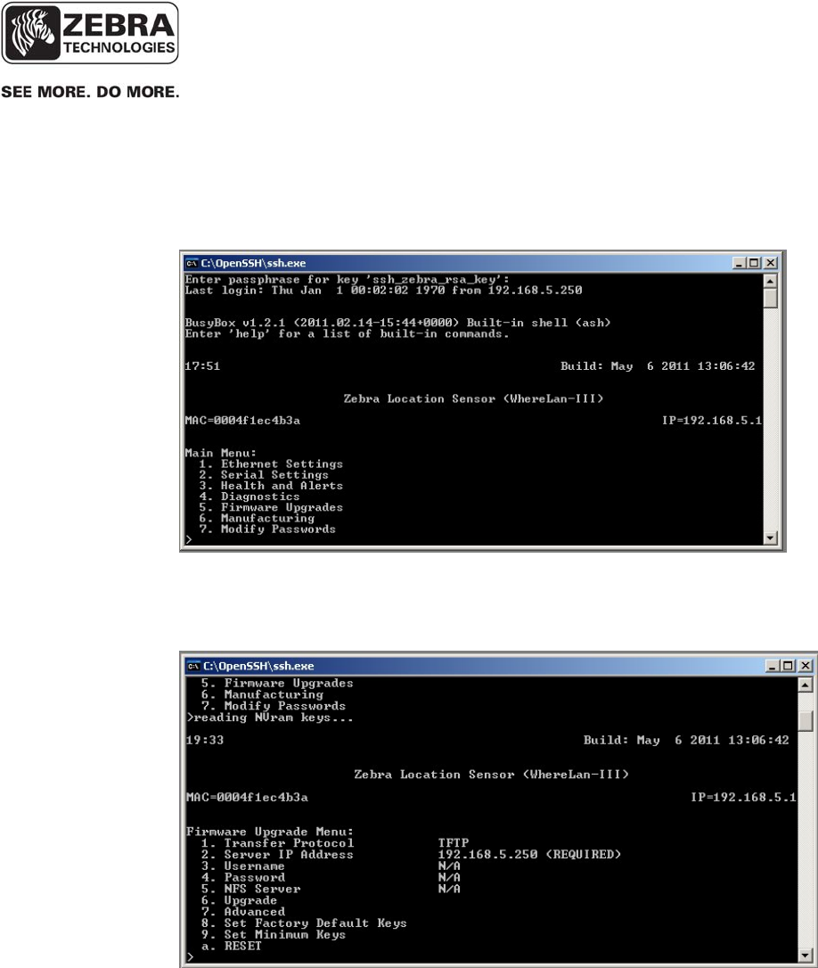
___________________________________________________________________________
WhereLAN III User’s Guide
___________________________________________________________________________ 94
User’s Guide, WhereLAN III draft D1675 rev F
© Copyright Zebra Technologies, 2012
Zebra Confidential
Figure 42 VSS Firmware 4.0.5.2 Directory
1. From the Main Menu select number that corresponds to ‘Firmware
Upgrade’.
2. Next select the file transfer method, ‘Transfer Protocol’ either TFTP or
FTP. Then set IP address of the Server where the files are located ‘Sever
IP Address’.
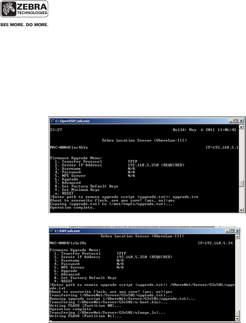
___________________________________________________________________________
WhereLAN III User’s Guide
___________________________________________________________________________ 95
User’s Guide, WhereLAN III draft D1675 rev F
© Copyright Zebra Technologies, 2012
Zebra Confidential
3. Now select the number that corresponds to ‘Upgrade’, and type
‘upgrade.txt’ at the prompt (enter/return) if files are located directly under
the ftproot directory (See Reference 1below). (OR) If the files located in
the inetpub/ftproot/WhereNet/Server/G3v501 directory (See Reference
2 below), then type “/wherenet/server/G3v501/upgrade.txt”, note the
direction of the slashes.
Then confirm to overwrite the flash, ‘yes’ (enter/return). The unit responds
with Operation Complete confirming that is has downloaded the firmware
files and has started the Flash Memory upgrade process.
Reference 1
Reference 2
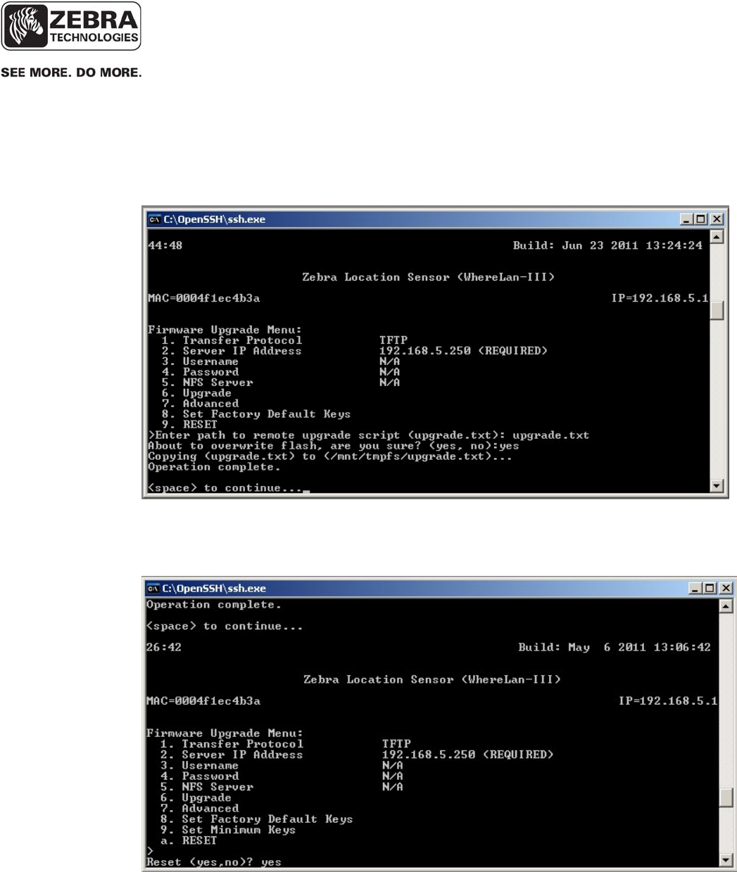
___________________________________________________________________________
WhereLAN III User’s Guide
___________________________________________________________________________ 96
User’s Guide, WhereLAN III draft D1675 rev F
© Copyright Zebra Technologies, 2012
Zebra Confidential
The when the unit has completed the Flash Memory upgrade process, it will
respond with “<space> to continue….”
4. Last Reset the unit (Reset) and ‘yes to confirm. Note on SSH or Telnet
this will end the session and the unit takes 45 to 60 seconds to completely
reboot.

___________________________________________________________________________
WhereLAN III User’s Guide
___________________________________________________________________________ 97
User’s Guide, WhereLAN III draft D1675 rev F
© Copyright Zebra Technologies, 2012
Zebra Confidential

___________________________________________________________________________
WhereLAN III User’s Guide
___________________________________________________________________________ 98
User’s Guide, WhereLAN III draft D1675 rev F
© Copyright Zebra Technologies, 2012
Zebra Confidential
APPENDIX E: HYPERTERMINAL BOOT SEQUENCE
U-Boot 1.1.4 (May 6 2011 - 14:27:47) Micrel, WhereNet 1.2
DRAM: 32 MB
Flash: 8 MB
In: serial
Out: serial
Err: serial
Enter "CTRL-Z" to abort autoboot in 3 seconds
## Booting image at 02020000 ...
Image Name: Linux-2.6.9-KS8695
Image Type: ARM Linux Kernel Image (uncompressed)
Data Size: 1441116 Bytes = 1.4 MB
Load Address: 00008000
Entry Point: 00008000
Verifying Checksum ... OK
OK
## Loading Ramdisk Image at 021a0000 ...
Image Name: Ram disk
Image Type: ARM Linux RAMDisk Image (gzip compressed)
Data Size: 2124742 Bytes = 2 MB
Load Address: 00800000
Entry Point: 00800000
Verifying Checksum ... OK
Starting kernel ...
Uncompressing Linux...................................................................................... done, booting the kernel.
Linux version 2.6.9-KS8695 (gcc version 3.4.5)
WhereNet Generation III
CPU: ARM922Tid(wb) [41029220] revision 0 (ARMv4T)
CPU: D VIVT write-back cache
CPU: I cache: 8192 bytes, associativity 64, 32 byte lines, 4 sets
CPU: D cache: 8192 bytes, associativity 64, 32 byte lines, 4 sets
Machine: Micrel Centaur
Memory policy: ECC disabled, Data cache writeback
Built 1 zonelists
Kernel command line: console=ttyAM0,19200
PID hash table entries: 256 (order: 8, 4096 bytes)
Console: colour dummy device 80x30
Dentry cache hash table entries: 8192 (order: 3, 32768 bytes)
Inode-cache hash table entries: 4096 (order: 2, 16384 bytes)
Memory: 32MB = 32MB total
Memory: 27488KB available (2205K code, 513K data, 68K init)
Mount-cache hash table entries: 512 (order: 0, 4096 bytes)
CPU: Testing write buffer coherency: ok

___________________________________________________________________________
WhereLAN III User’s Guide
___________________________________________________________________________ 99
User’s Guide, WhereLAN III draft D1675 rev F
© Copyright Zebra Technologies, 2012
Zebra Confidential
4 LED’s : The Kernel is initialized and is loading the applications, JFFS2 and CRAM
File system.
****** 4LED ******
checking if image is initramfs...it isn't (no cpio magic); looks like an initrd
Freeing initrd memory: 2074K
NET: Registered protocol family 16
PCI: bus0: Fast back to back transfers disabled
NetWinder Floating Point Emulator V0.97 (double precision)
JFFS2 version 2.2. (C) 2001-2003 Red Hat, Inc.
Initializing Cryptographic API
g3wdt version 1.0.0.0, 2007: margin 60 sec
RAMDISK driver initialized: 16 RAM disks of 5800K size 1024 blocksize
g3dev version 1.0.0.1, 2006
g3rtc version 1.0.0.1, 2011
i2c /dev entries driver
i2c_adapter i2c-0: found 2048 byte 24c16 I2C EEPROM (writable)
i2c_adapter i2c-0: found DS1780 CPU monitor
Serial: Micrel Centaur UART driver version: 2.6.1.0
ttyAM0 at MMIO 0x3ff0000 (irq = 8) is a KS8695
Serial: g3-8250/16x50 driver version: 1.00, IRQ sharing enabled
ttyS1 at MMIO 0x3200100 (irq = 5) is a 16550A
eth info: Micrel KS8695P Ethernet Network Driver, version 1.0.0.21, Copyright (c) 2002-2005 Micrel, Inc.
eth info: Icache mode = roundrobin
eth info: VA = 0xf03ff000, PA=0x03ff0000
eth info: VA = 0xf03ff000, PA=0x03ff0000
Using deadline io scheduler
physmap flash device: 800000 at 2000000
phys_mapped_flash: Found 2 x16 devices at 0x0 in 32-bit bank
Amd/Fujitsu Extended Query Table at 0x0040
number of CFI chips: 1
cfi_cmdset_0002: Disabling erase-suspend-program due to code brokenness.
cmdlinepart partition parsing not available
RedBoot partition parsing not available
Using physmap partition definition
Creating 5 MTD partitions on "phys_mapped_flash":
0x00000000-0x00020000 : "bootloader”
0x00020000-0x001a0000 : "kernel"
0x001a0000-0x00400000 : "ramdisk"
0x00400000-0x007e0000 : "jffs2"
0x007e0000-0x00800000 : "cramfs"
NET: Registered protocol family 2
IP: routing cache hash table of 512 buckets, 4Kbytes
TCP: Hash tables configured (established 2048 bind 4096)
NET: Registered protocol family 1

___________________________________________________________________________
WhereLAN III User’s Guide
___________________________________________________________________________
100
User’s Guide, WhereLAN III draft D1675 rev F
© Copyright Zebra Technologies, 2012
Zebra Confidential
Continued 4 LED’s : The Kernel is initialized and is loading the
applications, JFFS2 and CRAM File system.
1 LED (Power): The Application is loading the FPGA’s and DSP’s
NET: Registered protocol family 10
IPv6 over IPv4 tunneling driver
NET: Registered protocol family 17
ath_rate_amrr: 0.1 (0.9.4)
ath_pci: 0.9.4.5 (0.9.4)
ath_pci: No devices found, driver not installed.
ath_hal: 0.9.18.0 (AR5210, AR5211, AR5212, RF5111, RF5112, RF2413,RF5413, REGOPS_FUNC)
wlan: 0.9.4wlan: mac acl policy registered
RAMDISK: Compressed image found at block 0
VFS: Mounted root (ext2 filesystem).
init started: BusyBox v1.2.1 (2011.11.15-16:42+0000) multi-call binary
Disabled Privacy Extensions on device c028dbf0(lo)
BusyBox v1.2.1 (2011.11.15-16:42+0000) Built-in shell (ash)
Enter 'help' for a list of built-in commands.
WhereLan-III: Mar 19 2012 19:05:04
embedded tag rx service
started rx diagnostic receive process started
Executing coldboot.wsf
Configuring FPGA...
Opening file...done
Checking file...(1243888) bytes
Config mode...done
Loading...done

___________________________________________________________________________
WhereLAN III User’s Guide
___________________________________________________________________________
101
User’s Guide, WhereLAN III draft D1675 rev F
© Copyright Zebra Technologies, 2012
Zebra Confidential
2 LED’s (Power and Tag Reception): The unit is initializing the FPGA’s and DSP’s.
1 LED (Power): Unit is booted and will display health of unit.
Booting DSP's...
Opening file...done
Verifying AIS magic...done
Start-word synch...done
Ping opcode synch...done
Loading...done
Opening file...done
Verifying AIS magic...done
Start-word synch...done
Ping opcode synch...done
Loading...done
00004000: 00002000 -- -
00004000: 00002000 -- -
embedded transmit tag service started
MAC=0004f1ebc28e
creating tags:
lpn=f1ebc28c path=0800
lpn=f1ebc28d path=0100
lpn=f1ebc28e path=0200
lpn=f1ebc28f path=0400
Completed coldboot.wsf
00:39 Build: Mar 19 2012 19:05:04
Zebra Location Sensor (WhereLan-III)
MAC=0004f1ebc28e IP=192.168.5.34
Main Menu:
1. Ethernet Settings
2. Health and Alerts
3. Diagnostics
4. Firmware Upgrades
5. Manufacturing
>