Zebra Technologies MB82 MB82 Access Point Radio Module User Manual AP 650 Install Guide

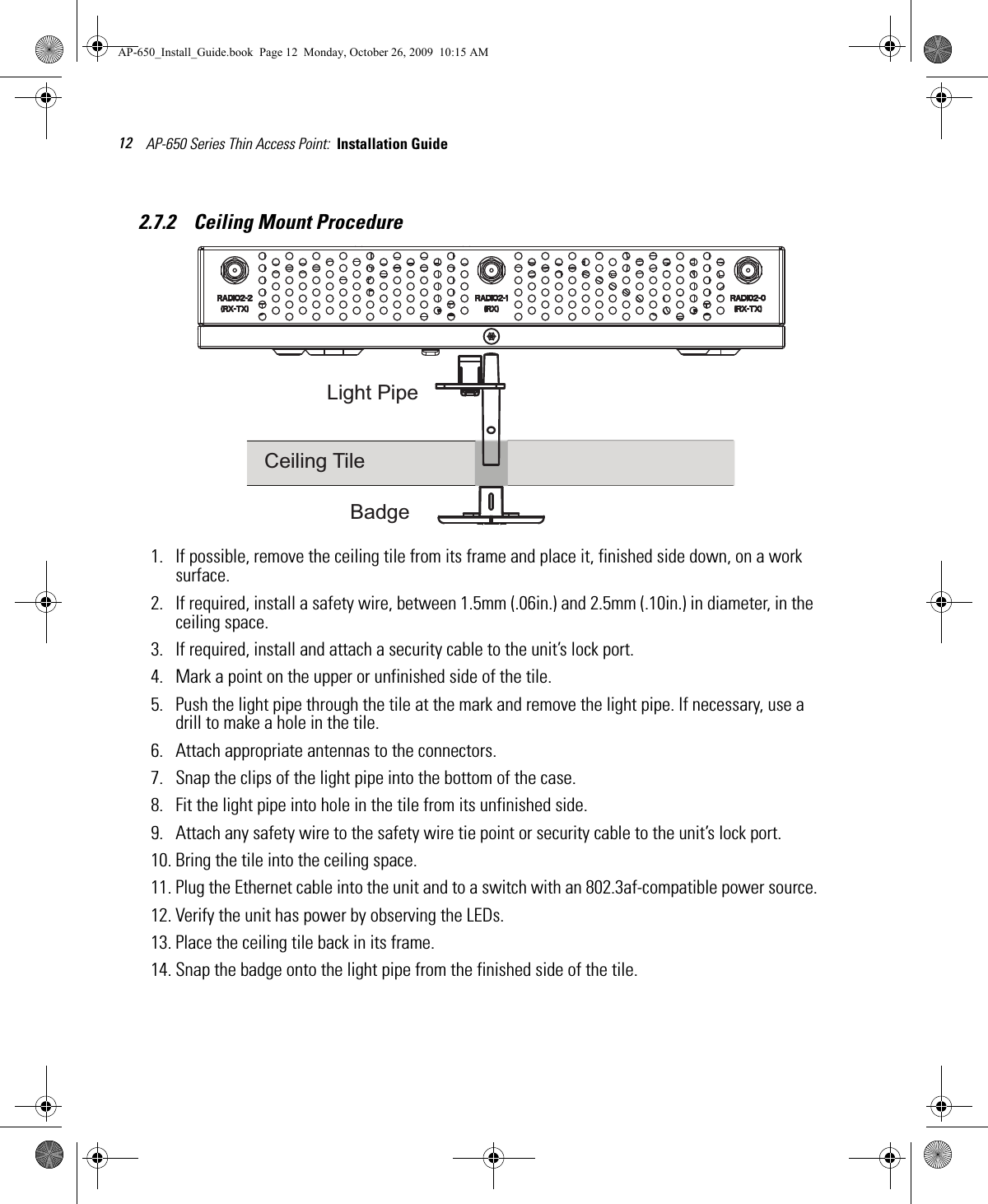
Zebra Technologies Corporation MB82 Access Point Radio Module AP 650 Install Guide
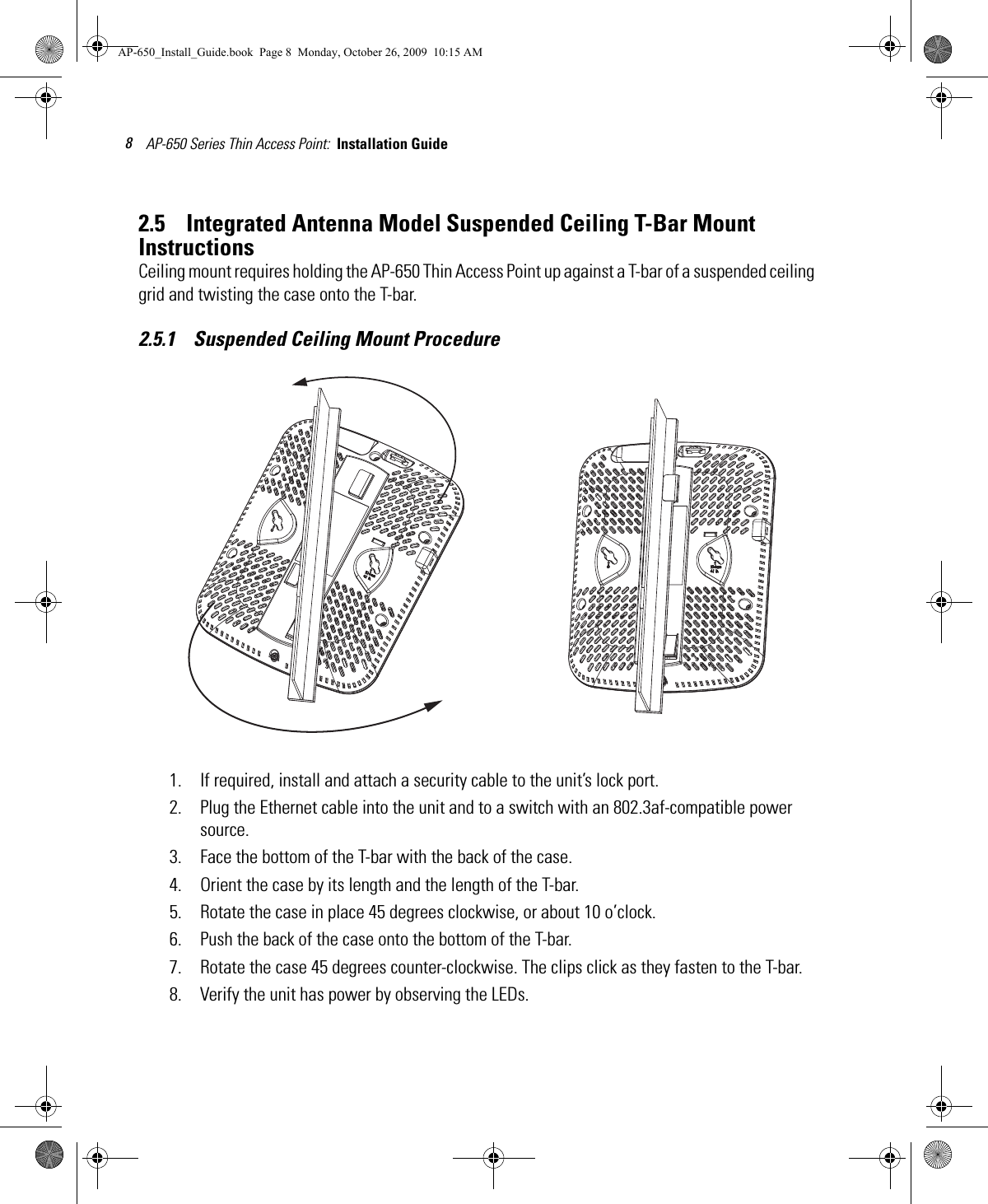
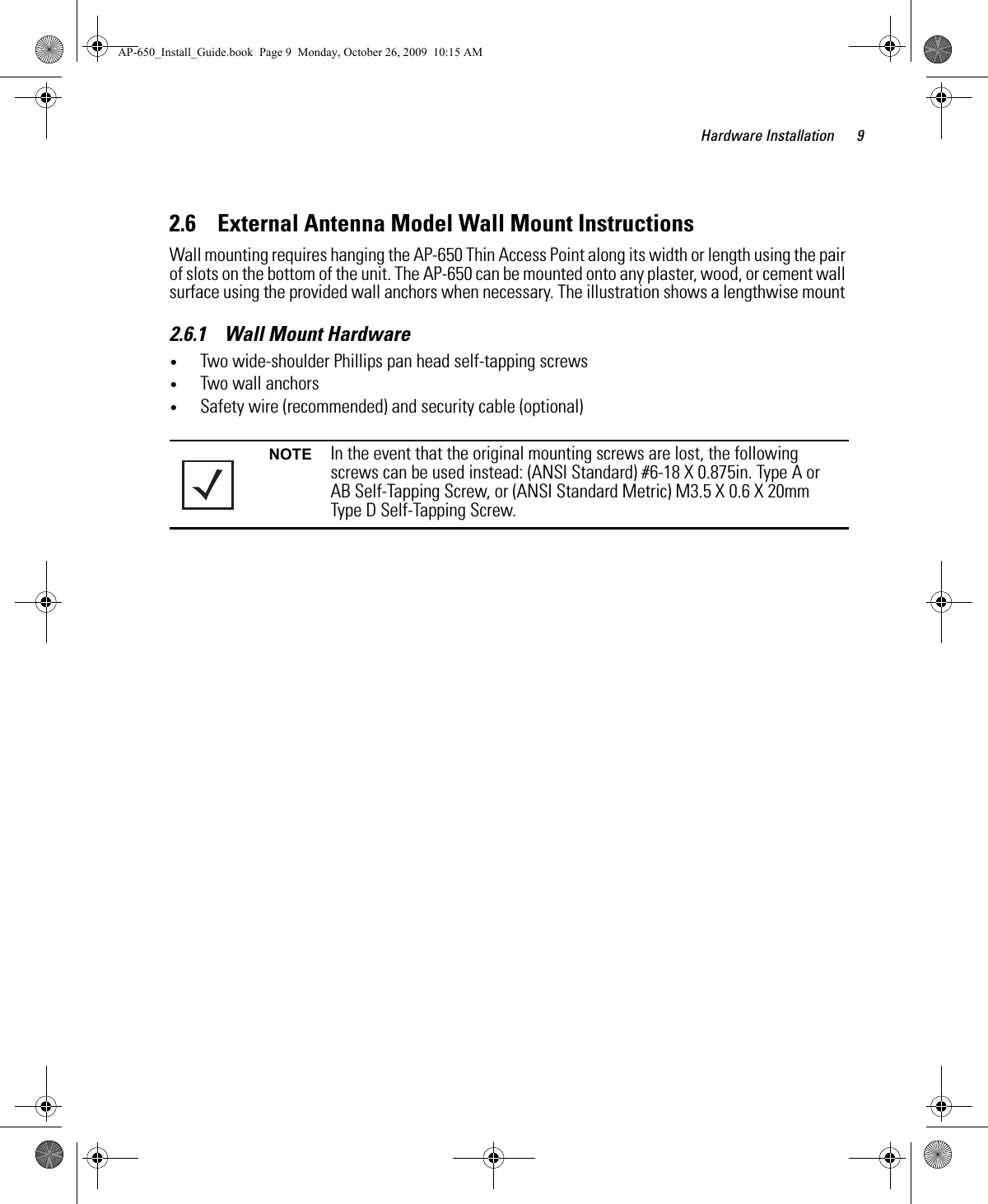
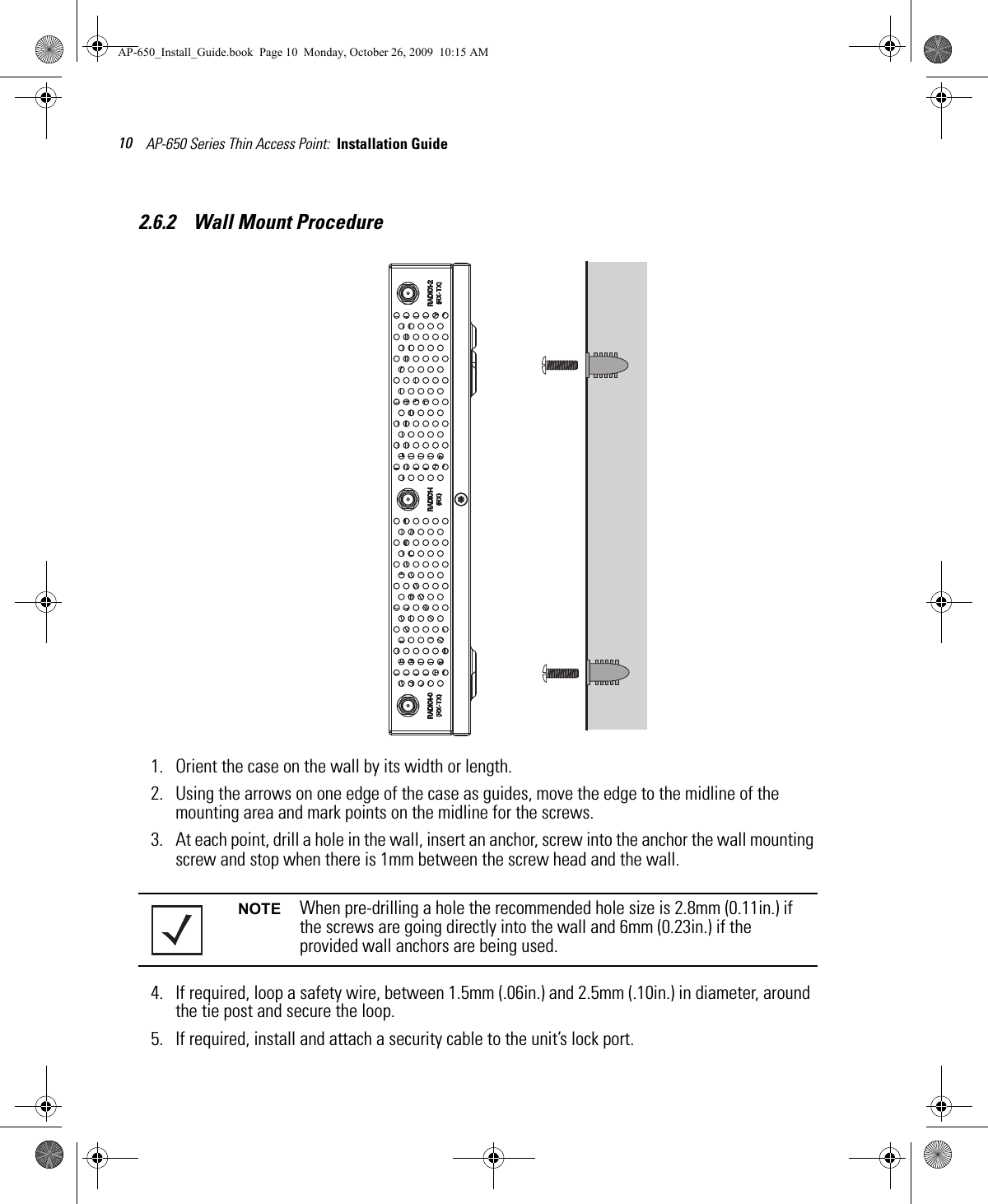
user manual

AP-650 Series Thin Access PointInstallation GuideMAP-650_Install_Guide.book  Page 1  Monday, October 26, 2009  10:15 AM
MOTOROLA and the Stylized M Logo are registered in the US Patent & Trademark Office. Symbol is a registered trademark of Symbol Technologies, Inc. All other product or service names are the property of their respective owners. © Motorola, Inc. 2009. All rights reserved.AP-650_Install_Guide.book  Page 2  Monday, October 26, 2009  10:15 AM
1    Introduction .......................................................................................... 11.1 Document Conventions .......................................................................................... 11.2 Warnings ................................................................................................................ 11.3 Site Preparation...................................................................................................... 21.4 AP-650 Package Contents ...................................................................................... 21.4.1 External Antenna Model Package Contents ............................................... 21.4.2 Integrated Antenna Model Package Contents............................................ 21.5 Features.................................................................................................................. 32    Hardware Installation ........................................................................ 42.1 Installation Instructions.......................................................................................... 42.2 Precautions............................................................................................................. 52.3 Access Point Placement ......................................................................................... 52.4 Integrated Antenna Model Wall Mount Instructions ............................................ 52.4.1 Wall Mount Hardware ................................................................................ 52.4.2 Wall Mount Procedure ................................................................................  62.5 Integrated Antenna Model Suspended Ceiling T-Bar Mount Instructions ............ 82.5.1 Suspended Ceiling Mount Procedure.......................................................... 82.6 External Antenna Model Wall Mount Instructions................................................  92.6.1 Wall Mount Hardware ................................................................................ 92.6.2 Wall Mount Procedure ..............................................................................  102.7 External Antenna Model Suspended Ceiling Tile (Plenum) Mount Instructions . 112.7.1 Suspended Ceiling Mount Hardware........................................................ 112.7.2 Ceiling Mount Procedure........................................................................... 122.8 AP-650 External Antenna Model Antenna Options ............................................. 132.9 LED Indicators....................................................................................................... 143    Specifications.................................................................................... 15Table of ContentsAP-650_Install_Guide.book  Page 1  Monday, October 26, 2009  10:15 AM
3.1 AP-650 External Antenna Model Electrical Characteristics ................................  153.2 AP-650 External Antenna Model Physical Characteristics .................................. 153.3 AP-650 Integrated Antenna Model Electrical Characteristics............................. 163.4 AP-650 Integrated Antenna Model Physical Characteristics............................... 163.5 Radio Characteristics ........................................................................................... 174    Regulatory Information..................................................................... 184.1 Regulatory Overview ............................................................................................ 184.2 Wireless Device Country Approvals..................................................................... 184.2.1 Country Selection – Note for AP & Wireless Switch ...............................  184.2.2 Frequency of Operation – FCC and IC ....................................................... 194.3 Health and Safety Recommendations.................................................................. 194.3.1 Warnings for the use of Wireless Devices............................................... 194.3.2 Potentially Hazardous Atmospheres – Fixed Installations ....................... 194.3.3 Safety in Hospitals .................................................................................... 194.4 RF Exposure Guidelines........................................................................................ 204.4.1 Safety Information..................................................................................... 204.5 International ......................................................................................................... 204.6  EU ....................................................................................................................... 204.7 US and Canada..................................................................................................... 204.8 Power Supply........................................................................................................ 214.9 Radio Frequency Interference Requirements—FCC ............................................ 214.10 Radio Frequency Interference Requirements – Canada  ................................... 214.10.1 Radio Transmitters .................................................................................. 214.11 CE Marking and European Economic Area (EEA) ............................................... 224.12 Statement of Compliance................................................................................... 224.13 Waste Electrical and Electronic Equipment (WEEE) .......................................... 234.14 TURKISH WEEE Statement of Compliance ........................................................ 244.15 Japan (VCCI) - Voluntary Control Council for Interference Class B ITE  ............. 244.16 Korea Warning Statement for Class B ITE......................................................... 254.17 Other Countries .................................................................................................. 254.17.1 Australia .................................................................................................. 254.17.2 Brazil........................................................................................................ 25AP-650_Install_Guide.book  Page 2  Monday, October 26, 2009  10:15 AM
4.17.3 Chile ........................................................................................................ 254.17.4 Mexico..................................................................................................... 264.17.5 Taiwan..................................................................................................... 264.17.6 Korea ....................................................................................................... 275    Motorola’s Enterprise Mobility Support Center .......................... 285.1 Customer Support Web Sites............................................................................... 285.2 Manuals................................................................................................................ 285.3 General Information ............................................................................................. 286    AP-650 Series ROHS Compliance................................................... 29AP-650_Install_Guide.book  Page 3  Monday, October 26, 2009  10:15 AM
Introduction 11 IntroductionThe AP-650 Thin Access Point, a component of the Motorola Wireless Switch System, links wireless 802.11a/b/g/n devices to the switch, enabling growth of your wireless network with a cost-effective alternative to standard access points. The AP-650 Thin Access Point provides two placement options: wall and ceiling. Wall mount slots fit onto two screws provided. Arrows on the case guide placement of the screws. For placement above a suspended ceiling, a safety wire tie point on the case provides for a loop of safety wire. The light pipe fits through a hole in the ceiling tile to provide a view of the unit’s status lights.The AP-650 Thin Access Point receives all power and transfers data through the same CAT-5 or better Ethernet cable. There is no additional power supply required. An 802.3af Ethernet switch or power injector is required.1.1    Document ConventionsThe following graphical alerts are used in this document to indicate notable situations: 1.2    Warnings•Read all installation instructions and site survey reports, and verify correct equipment installation before connecting the AP-650 Thin Access Point.•Remove jewelry and watches before installing this equipment. •Verify that the unit is grounded before connecting it to the power source. •Verify that any device connected to this unit is properly wired and grounded.•Verify there is adequate ventilation around the device, and that ambient temperatures meet equipment operation specifications.NOTE Tips, hints, or special requirements that you should take note of.CAUTION Care is required. Disregarding a caution can result in data loss or equipment malfunction.WARNING! Indicates a condition or procedure that could result in personal injury or equipment damage.!AP-650_Install_Guide.book  Page 1  Monday, October 26, 2009  10:15 AM
AP-650 Series Thin Access Point:  Installation Guide 21.3    Site Preparation•Consult your site survey and network analysis reports to determine specific equipment placement, power drops, and so on. •Assign installation responsibility to the appropriate personnel.•Identify and document where all installed components are located.•Ensure adequate, dust-free ventilation to all installed equipment.•Identify and prepare Ethernet and console port connections.•Verify that cable lengths are within the maximum allowable distances for optimal signal transmission.1.4    AP-650 Package ContentsThe AP-650 model Thin Access Point comes in four configurations, two Integrated Antenna models and two External Antenna models. The contents of the package differ between the Integrated Antenna model and the External Antenna model.1.4.1    External Antenna Model Package Contents•AP-650 Thin Access Point with external antenna connectors (Plenum Rated)•Two wall mount screws•Two wall anchors•Light pipe•Badge for light pipe•AP-650 Installation Guide (This Guide)1.4.2    Integrated Antenna Model Package Contents•AP-650 Thin Access Point with integrated antennas•Two wall mount screws•Two wall anchors•AP-650 Installation Guide (This Guide)AP-650_Install_Guide.book  Page 2  Monday, October 26, 2009  10:15 AM
Introduction 31.5    Features•One RJ-45 connector•LED indicators•Safety wire tie point•Slots for wall mounting•Clips for mounting on a suspended ceiling T-bar•Lock port for Kensington® style Security LockThe AP-650 Thin Access Point has one RJ-45 connector supporting an 10/100/1000 Ethernet port and requires 802.3af-compliant power from an external source.The AP-650 Thin Access Point comes in both single and dual radio versions both supporting 802.11a/b/g/n.The Thin Access Point contains runtime firmware which enables the unit to boot after either a power up or a watchdog reset. The runtime firmware on the Thin Access Point and the firmware downloaded from the switch can be updated via the Ethernet interface from the Wireless Switch.NOTE When operating in a Gigabit Ethernet environment CAT-5e or CAT-6 cable is required for Gigabit operation.AP-650_Install_Guide.book  Page 3  Monday, October 26, 2009  10:15 AM
AP-650 Series Thin Access Point:  Installation Guide 42 Hardware Installation2.1    Installation InstructionsThe AP-650 Thin Access Point mounts either on a wall with wide-shoulder screws or on a suspended ceiling T-bar. This unit is not designed for mounting on a desk.To prepare for installation, perform the following steps:1. Match the model number on the purchase order with the model numbers in the packing list and on the case of the device shipped.2. Verify that the contents of the box include the intended AP-650 Thin Access Point and that the included hardware matches the package contents on page 2.3. Review site survey and network analysis reports to determine the location and mounting position for the AP-650 Thin Access Point.4. Connect a CAT-5 or better Ethernet cable to a compatible 802.3af power source and run the cable to the installation site. Ensure that there is sufficient slack on the cable to perform the installation steps.Part Number DescriptionAP-0650-60010-XX 802.11a/b/g/n single radio integrated antenna configurationAP-0650-66020-XX 802.11a/b/g/n dual radio integrated antenna configurationAP-0650-60030-XX 802.11a/b/g/n single radio external antenna configurationAP-0650-66040-XX 802.11a/b/g/n dual radio external antenna configurationNOTE In the above part numbers XX represents the 2-digit country code which specifies which country the model is designed for. A country code of “WW” represents a world wide model.NOTE When operating in a Gigabit Ethernet environment CAT-5e or CAT-6 cable is required for Gigabit operation.AP-650_Install_Guide.book  Page 4  Monday, October 26, 2009  10:15 AM
Hardware Installation 52.2    PrecautionsBefore installing an AP-650 model Thin Access Point, verify the following:• Motorola recommends not to install the AP-650 in wet or dusty areas.• Verify the environment has a continuous temperature range between 0° C to 50° C.2.3    Access Point PlacementFor optimal performance, install the access point away from transformers, heavy-duty motors, fluorescent lights, microwave ovens, refrigerators and other industrial equipment. Signal loss can occur when metal, concrete, walls or floors block transmission. Install the access point in an open area or add access points as needed to improve coverage.Antenna coverage is analogous to lighting. Users might find an area lit from far away to be not bright enough. An area lit sharply might minimize coverage and create dark areas. Uniform antenna placement in an area (like even placement of a light bulb) provides even, efficient coverage.Place the access point using the following guidelines:• Install the access point at an ideal height of 10 feet from the ground.• Orient the access point antennas vertically for best reception.To maximize the access point’s radio coverage area, Motorola recommends conducting a site survey to define and document radio interference obstacles before installing the access point.2.4    Integrated Antenna Model Wall Mount InstructionsThis mounting requires hanging the AP-650 Thin Access Point along its width or length using the two slots on the bottom of the unit. The AP-650 can be mounted onto any plaster, wood, or cement wall surface using the provided wall anchors when necessary. The illustration shows a lengthwise mount.2.4.1    Wall Mount Hardware•Two wide-shoulder Phillips pan head self-tapping screws•Two wall anchors•Security cable (optional)NOTE In the event that the original mounting screws are lost, the following screws can be used instead: (ANSI Standard) #6-18 X 0.875in. Type A or AB Self-Tapping Screw, or (ANSI Standard Metric) M3.5 X 0.6 X 20mm Type D Self-Tapping Screw.AP-650_Install_Guide.book  Page 5  Monday, October 26, 2009  10:15 AM
AP-650 Series Thin Access Point:  Installation Guide 62.4.2    Wall Mount Procedure1. Orient the case on the wall by its width or length.2. Using the arrows on one edge of the case as guides, move the edge to the midline of the mounting area and mark points on the midline for the screwsCAUTION To ensure proper operation of the AP-650 Thin Access Point ensure that the thin access point is mounted in the correct orientation as shown above.Integrated Antenna Wall Mount Correct Orientation Incorrect Orientation!AP-650_Install_Guide.book  Page 6  Monday, October 26, 2009  10:15 AM
Hardware Installation 73. At each point, drill a hole in the wall, insert an anchor, screw into the anchor the wall mounting screw and stop when there is 1mm between the screw head and the wall.4. If required, install and attach a security cable to the unit’s lock port.5. Attach the Ethernet cable to the unit and to a switch with an 802.3af-compatible power source.6. Place the middle of each of the case’s mount slots over the screw heads.7. Slide the case down along the mounting surface to hang the mount slots on the screw heads.8. Verify the unit has power by observing that the LEDs are lit or flashing.NOTE When pre-drilling a hole the recommended hole size is 2.8mm (0.11in.) if the screws are going directly into the wall and 6mm (0.23in.) if the provided wall anchors are being used.AP-650_Install_Guide.book  Page 7  Monday, October 26, 2009  10:15 AM
AP-650 Series Thin Access Point:  Installation Guide 82.5    Integrated Antenna Model Suspended Ceiling T-Bar Mount InstructionsCeiling mount requires holding the AP-650 Thin Access Point up against a T-bar of a suspended ceiling grid and twisting the case onto the T-bar.2.5.1    Suspended Ceiling Mount Procedure1. If required, install and attach a security cable to the unit’s lock port.2. Plug the Ethernet cable into the unit and to a switch with an 802.3af-compatible power source.3. Face the bottom of the T-bar with the back of the case.4. Orient the case by its length and the length of the T-bar.5. Rotate the case in place 45 degrees clockwise, or about 10 o’clock.6. Push the back of the case onto the bottom of the T-bar.7. Rotate the case 45 degrees counter-clockwise. The clips click as they fasten to the T-bar.8. Verify the unit has power by observing the LEDs.AP-650_Install_Guide.book  Page 8  Monday, October 26, 2009  10:15 AM
Hardware Installation 92.6    External Antenna Model Wall Mount InstructionsWall mounting requires hanging the AP-650 Thin Access Point along its width or length using the pair of slots on the bottom of the unit. The AP-650 can be mounted onto any plaster, wood, or cement wall surface using the provided wall anchors when necessary. The illustration shows a lengthwise mount 2.6.1    Wall Mount Hardware•Two wide-shoulder Phillips pan head self-tapping screws•Two wall anchors•Safety wire (recommended) and security cable (optional)NOTE In the event that the original mounting screws are lost, the following screws can be used instead: (ANSI Standard) #6-18 X 0.875in. Type A or AB Self-Tapping Screw, or (ANSI Standard Metric) M3.5 X 0.6 X 20mm Type D Self-Tapping Screw.AP-650_Install_Guide.book  Page 9  Monday, October 26, 2009  10:15 AM
AP-650 Series Thin Access Point:  Installation Guide 102.6.2    Wall Mount Procedure1. Orient the case on the wall by its width or length.2. Using the arrows on one edge of the case as guides, move the edge to the midline of the mounting area and mark points on the midline for the screws.3. At each point, drill a hole in the wall, insert an anchor, screw into the anchor the wall mounting screw and stop when there is 1mm between the screw head and the wall.4. If required, loop a safety wire, between 1.5mm (.06in.) and 2.5mm (.10in.) in diameter, around the tie post and secure the loop.5. If required, install and attach a security cable to the unit’s lock port.NOTE When pre-drilling a hole the recommended hole size is 2.8mm (0.11in.) if the screws are going directly into the wall and 6mm (0.23in.) if the provided wall anchors are being used.AP-650_Install_Guide.book  Page 10  Monday, October 26, 2009  10:15 AM
Hardware Installation 116. Place the large corner of each of the case’s mount slots over the screw heads.7. Slide the case down along the mounting surface to hang the mount slots on the screw heads.8. Attach appropriate antennas to the connectors.9. Attach the Ethernet cable to the unit and to a switch with an 802.3af compatible power source.10. Verify the unit has power by observing that the LEDs are lit or flashing.2.7    External Antenna Model Suspended Ceiling Tile (Plenum) Mount InstructionsCeiling mount requires placing the AP-650 Thin Access Point above a suspended ceiling and installing the provided light pipe for viewing the status lights of the unit. This placement requires installation of the provided light pipe for viewing the status lights of the unit.2.7.1    Suspended Ceiling Mount Hardware•Light pipe•Badge for light pipe•Safety wire (recommended) and security cable (optional)NOTE Notes or warnings about suspended ceiling mounts apply to all installations where the unit is placed on suspended ceiling tile. The case has a safety wire tie point for a standard safety wire.CAUTION Motorola does not recommend mounting the AP-650 Thin Access Point directly to any suspended ceiling tile with a thickness less than 12.7mm (0.5in.) or a suspended ceiling tile with an unsupported span greater than 660mm (26in.). Motorola strongly recommends fitting the AP-650 Thin Access Point with a safety wire suitable for the specific installation. The safety wire should be a standard ceiling suspension cable or equivalent steel wire between 1.59mm (.062in.) and 2.5mm (.10in.) in diameter. !AP-650_Install_Guide.book  Page 11  Monday, October 26, 2009  10:15 AM
AP-650 Series Thin Access Point:  Installation Guide 122.7.2    Ceiling Mount Procedure1. If possible, remove the ceiling tile from its frame and place it, finished side down, on a work surface.2. If required, install a safety wire, between 1.5mm (.06in.) and 2.5mm (.10in.) in diameter, in the ceiling space.3. If required, install and attach a security cable to the unit’s lock port.4. Mark a point on the upper or unfinished side of the tile.5. Push the light pipe through the tile at the mark and remove the light pipe. If necessary, use a drill to make a hole in the tile.6. Attach appropriate antennas to the connectors.7. Snap the clips of the light pipe into the bottom of the case.8. Fit the light pipe into hole in the tile from its unfinished side.9. Attach any safety wire to the safety wire tie point or security cable to the unit’s lock port.10. Bring the tile into the ceiling space.11. Plug the Ethernet cable into the unit and to a switch with an 802.3af-compatible power source.12. Verify the unit has power by observing the LEDs.13. Place the ceiling tile back in its frame.14. Snap the badge onto the light pipe from the finished side of the tile.BadgeCeiling TileLight PipeAP-650_Install_Guide.book  Page 12  Monday, October 26, 2009  10:15 AM
Hardware Installation 132.8    AP-650 External Antenna Model Antenna OptionsMotorola supports two antenna suites for AP-650 External Antenna models. One antenna suite supporting the 2.4 GHz band and another antenna suite supporting the 5 GHz band. Select an antenna model best suited to the intended operational environment of your access point.On single radio versions, the R-SMA connectors can support both bands and should be connected to a R-SMA dual-band antenna or an appropriate single band antenna. The 2.4 GHz antenna suite includes the following models:The 5 GHz antenna suite includes the following models:For up-to-date information on supported antennas and antenna specifications please see the Motorola Antenna Specification Guide available on the Motorola website.Part Number Antenna TypeML-2499-HPA3-01R Omni-Directional Antenna ML-2499-SD3-01R Patch AntennaML-2452-APA2-01 Dual-BandML-2452-PNA5-01R Panel AntennaML-2452-PTA3M3-036 Omni-Directional AntennaPart Number Antenna TypeML-5299-HPA1-01R Omni-Directional Antenna ML-5299-PTA1-01R Patch AntennaML-2452-APA2-01 Dual-BandML-2452-PNA5-01R Panel AntennaML-2452-PTA3M3-036 Omni-Directional AntennaAP-650_Install_Guide.book  Page 13  Monday, October 26, 2009  10:15 AM
AP-650 Series Thin Access Point:  Installation Guide 142.9    LED IndicatorsBoth the Integrated Antenna model and the External Antenna model have LED activity indicators on the front of the case for use with wall mount. With the External Antenna model unit mounted above a ceiling, LEDs are at the center of an oval badge on the ceiling; a light pipe enables viewing the back LEDs through the ceiling tile.The LEDs provide a status display indicating error conditions, transmission, and network activity for the 5 GHz 802.11a/n (amber) radio or the 2.4 GHz 802.11b/g/n (green) radio.Task 5 GHz Activity LED Amber2.4 GHz Activity LED Greenntenna TypeBooting The amber LED flashes three times per second until firmware is loaded. During boot, 802.11a/n mobiles cannot associate.The green LED flashes three times per second until firmware is loaded. During boot, 802.11b/g/n mobiles cannot associate.Normal After adoption, the amber LED is steady or flashes with 802.11a/n radio traffic.After adoption, the green LED is steady or flashes with 802.11b/g/n radio traffic.End The amber LED flashes once per second if an error prevents the 802.11a/n radio from operating normally.The green LED flashes once per second if an error prevents the 802.11b/g/n radio from operating normally.AP-650_Install_Guide.book  Page 14  Monday, October 26, 2009  10:15 AM
Specifications 153 Specifications3.1    AP-650 External Antenna Model Electrical CharacteristicsAn AP-650 External Antenna model Thin Access Point has the following electrical characteristics:  3.2    AP-650 External Antenna Model Physical CharacteristicsAn AP-650 External Antenna model Thin Access Point has the following physical characteristics:  Operating Current & Voltage180ma- 270ma @ 48VDCDimensions 8.50 in. Depth x 5.5 in. Width x 1.5 in. Height21.59 cm Depth x 13.97 cm Width x 3.81 cm HeightHousing MetalWeight 2.5 lbs / 1.13 kgOperating Temperature32°F to 122°F/0°C to 50°CStorage Temperature -40°F to 185°F/-40°C to 85°COperating Humidity 5 to 95% Relative Humidity non-condensingStorage Humidity 85% Relative Humidity non-condensingOperating Altitude(max)8,000 ft @ 28CStorage Altitude(max)30,000 ft @ 12CElectrostatic Discharge+/-15kV Air and +/-8kV Contact @ 50% Relative HumidityAP-650_Install_Guide.book  Page 15  Monday, October 26, 2009  10:15 AM
AP-650 Series Thin Access Point:  Installation Guide 163.3    AP-650 Integrated Antenna Model Electrical CharacteristicsAn AP-650 Integrated model Thin Access Point has the following electrical characteristics:  3.4    AP-650 Integrated Antenna Model Physical CharacteristicsAn AP-650 Integrated Antenna model Thin Access Point has the following physical characteristics:  Operating Current & Voltage180ma- 270ma @ 48VDCDimensions 9.50 in. Depth x 7.5 in. Width x 1.9 in. Height24.13 cm Depth x 19.05 cm Width x 4.83 cm HeightHousing PlasticWeight 2.0 lbs / 0.91 kgOperating Temperature32°F to 122°F/0°C to 50°CStorage Temperature -40°F to 185°F/-40°C to 85°COperating Humidity 5 to 95% Relative Humidity non-condensingStorage Humidity 85% Relative Humidity non-condensingOperating Altitude(max)8,000 ft @ 28CStorage Altitude(max)30,000 ft @ 12CElectrostatic Discharge+/-15kV Air and +/-8kV Contact @ 50% Relative HumidityAP-650_Install_Guide.book  Page 16  Monday, October 26, 2009  10:15 AM
Specifications 173.5    Radio CharacteristicsThe AP-650 model Thin Access Points have the following radio characteristics: Operating Channels All channels from 4920 MHz to 5825 MHz except channel 52 -64Channels 1-13 (2412-2472 MHz)Channel 14 (2484 MHz) Japan onlyActual operating frequencies depend on regulatory approval for the country of use.Data Rates Supported 802.11g: 1,2,5.5,11,6,9,12,18,24,36,48, and 54Mbps802.11a: 6,9,12,18,24,36,48, and 54Mbps802.11n: MCS 0-15 up to 300MbpsWireless Medium Direct Sequence Spread Spectrum (DSSS),Orthogonal Frequency Division Multiplexing (OFDM)Spatial multiplexing (MIMO)Network Standards 802.11a, 802.11b, 802.11g, 802.3, 802.11n (Draft 2.0)Maximum Available Transmit PowerMaximum available conducted transmit power per chain: 2.4 GHz: 21dBmMaximum available conducted transmit power all chains: 2.4 GHz: 24dBmMaximum available conducted transmit power per chain: 5 GHz: 19dBmMaximum available conducted transmit power all chains: 5 GHz: 22dBmTransmit Power Adjustment1dB incrementsAntenna Configuration2x3 MIMO (transmit on two and receive on all threeantennas)AP-650_Install_Guide.book  Page 17  Monday, October 26, 2009  10:15 AM
AP-650 Series Thin Access Point:  Installation Guide 184 Regulatory Information4.1    Regulatory OverviewThis device is approved under the Symbol Technologies brand: Symbol Technologies, Inc., is the Enterprise Mobility business of Motorola, Inc. (“Motorola”).This guide applies to Model Number AP-650All Motorola/Symbol devices are designed to be compliant with rules and regulations in locations they are sold and will be labeled as required. Local language translations are available at the following website: http://support.symbol.comAny changes or modifications to Motorola/Symbol Technologies equipment, not expressly approved by Motorola/Symbol Technologies, could void the user’s authority to operate the equipment.Motorola/Symbol Access Points must be professionally installed and configured so that the Radio Frequency Output Power will not exceed the maximum allowable limit for the country of operation.Antennas: Use only the supplied or an approved replacement antenna. Unauthorized antennas, modifications, or attachments could cause damage and may violate regulations.  Use of and unapproved antenna is illegal under FCC regulations subjecting the end user to fines and equiment sesure.Radio ModulesThis Access Point contains approved radio module(s) MB82.  These module(s) are identified below. MB82 – a DFS Master WLAN 802.11 abgn MIMO 3x3 radio module. 4.2    Wireless Device Country ApprovalsRegulatory markings, subject to certification, are applied to the device signifying the radio(s) is/are approved for use in the following countries:  United States, Canada, Japan, China, S. Korea, Australia, and Europe.Please refer to the Symbol Declaration of Conformity (DoC) for details of other country markings. This is available at http://www2.symbol.com/doc/.Note: For 2.4GHz or 5GHz Products: Europe includes, Austria, Belgium, Bulgaria, Czech Republic, Cyprus, Denmark, Estonia, Finland, France, Germany, Greece, Hungary, Iceland, Ireland, Italy, Latvia, Liechtenstein, Lithuania, Luxembourg, Malta, Netherlands, Norway, Poland, Portugal, Romania, Slovak Republic, Slovenia, Spain, Sweden, Switzerland and the United Kingdom.AP-650_Install_Guide.book  Page 18  Monday, October 26, 2009  10:15 AM
Regulatory Information 19Operation of the device without regulatory approval is illegal.4.2.1    Country Selection – Note for AP & Wireless SwitchSelect only the country in which you are using the device. Any other selection will make the operation of this device illegal.  The US version of the Access Point only lists US in the Country Selection List. 4.2.2    Frequency of Operation – FCC and IC 5 GHz OnlyThe use in the UNII (Unlicensed National Information Infrastructure) band 1 5150-5250 MHz band and band 3 5470-5725 MHz is restricted to Indoor Use Only; any other use will make the operation of this device illegal. Any device labeled INDOOR USE ONLY may not be legally used outdoors.2.4 GHz OnlyThe available channels for 802.11 b/g operation in the US are Channels 1 to 11. The range of channels is limited by firmware.4.3    Health and Safety Recommendations4.3.1    Warnings for the use of Wireless Devices Please observe all warning notices with regard to the usage of wireless devices4.3.2    Potentially Hazardous Atmospheres – Fixed InstallationsYou are reminded of the need to observe restrictions on the use of radio devices in fuel depots, chemical plants etc. and areas where the air contains chemicals or particles (such as grain, dust, or metal powders).4.3.3    Safety in HospitalsWireless devices transmit radio frequency energy and may affect medical electrical equipment. When installed adjacent to other equipment, it is advised to verify that the adjacent equipment is not adversely affected.PacemakersPacemaker manufacturers recommended that a minimum of 15cm (6 inches) be maintained between a handheld wireless device  and a pacemaker to avoid potential  interference with the pacemaker. These recommendations are consistent with independent research and recommendations by Wireless Technology Research.AP-650_Install_Guide.book  Page 19  Monday, October 26, 2009  10:15 AM
AP-650 Series Thin Access Point:  Installation Guide 20Persons with Pacemakers:• Should ALWAYS keep the device more than 15cm (6 inches) from their pacemaker when turned ON.• Should not carry the device in a breast pocket.• Should use the ear furthest from the pacemaker to minimize the potential for interference.• If you have any reason to suspect that interference is taking place, turn OFF your device. Other Medical DevicesPlease consult your physician or the manufacturer of the medical device, to determine if the operation of your  wireless product may interfere with the medical device.4.4    RF Exposure Guidelines4.4.1    Safety InformationReducing RF Exposure—Use ProperlyOnly operate the device in accordance with the instructions supplied.4.5    InternationalThe device complies with internationally recognized standards covering human exposure to electromagnetic fields from radio devices.  For information on “International” human exposure to eletromagnic fields refer to the Motorola/Symbol Declaration of Conformity (DoC) at  http://www2.symbol.com/doc/.4.6    EURemote and Standalone Antenna ConfigurationsTo comply with EU RF exposure requirements, antennas that are mounted externally at remote locations or operating near users at stand-alone desktop of similar configurations must operate with a minimum separation distance of 20 cm from all persons.4.7    US and CanadaCo-located statementTo comply with FCC RF exposure compliance requirement, the antennas used for this transmitter must not be co-located or operating in conjunction with any other transmitter/antenna except those already approved in this filling.AP-650_Install_Guide.book  Page 20  Monday, October 26, 2009  10:15 AM
Regulatory Information 21Remote and Standalone Antenna ConfigurationsTo comply with FCC RF exposure requirements, antennas that are mounted externally at remote locations or operating near users at stand-alone desktop of similar configurations must operate with a minimum separation distance of 20 cm from all persons.4.8    Power SupplyThis device is powered from a 802.3af compliant power source which is UL approved and certified by the appropriate agencies.4.9    Radio Frequency Interference Requirements—FCCThis equipment has been tested and found to comply with the limits for a Class B digital device, pursuant to Part 15 of the FCC rules. These limits are designed to provide reasonable protection against harmful interference in a residential installation. This equipment generates, uses and can radiate radio frequency energy and, if not installed and used in accordance with the instructions, may cause harmful interference to radio communications. However there is no guarantee that interference will not occur in a particular installation. If this equipment does cause harmful interference to radio or television reception, which can be determined by turning the equipment off and on, the user is encouraged to try to correct the interference by one or more of the following measures:• Reorient or relocate the receiving antenna• Increase the separation between the equipment and receiver• Connect the equipment into an outlet on a circuit different from that to which the receiver is connected• Consult the dealer or an experienced radio/TV technician for helpRadio Transmitters (Part 15)This device complies with Part 15 of the FCC Rules. Operation is subject to the following two conditions: (1) this device may not cause harmful interference, and (2) this device must accept any interference received, including interference that may cause undesired operation.Restricted Band 5.60 – 5.65 GHz 4.10    Radio Frequency Interference Requirements – Canada This Class B digital apparatus complies with Canadian ICES-003.Cet appareil numérique de la classe B est conforme à la norme NMB-003 du Canada.AP-650_Install_Guide.book  Page 21  Monday, October 26, 2009  10:15 AM
AP-650 Series Thin Access Point:  Installation Guide 224.10.1    Radio TransmittersFor RLAN Devices:The use of 5 GHz RLAN’s, for use in Canada, have the following restrictions:• Restricted Band 5.60 – 5.65 GHz This device complies with RSS 210 of Industry & Science Canada. Operation is subject to the following two conditions: (1) this device may not cause harmful interference and (2) this device must accept any interference received, including interference that may cause undesired operation.Label Marking: The Term "IC:" before the radio certification only signifies that Industry Canada technical specifications were met.4.11    CE Marking and European Economic Area (EEA)The use of 2.4 GHz RLAN’s, for use through the EEA, have the following restrictions:• Maximum radiated transmit power of 100 mW EIRP in the frequency range 2.400 -2.4835 GHz.• France, outside usage is restricted to 2.4 – 2.454 GHz. • Italy requires a user license for outside usage.4.12    Statement of ComplianceMotorola/Symbol hereby, declares that this device is in compliance with the essential requirements and other relevant provisions of Directive 1999/5/EC. A Declaration of Conformity may be obtained from http://www2.symbol.com/doc/.AP-650_Install_Guide.book  Page 22  Monday, October 26, 2009  10:15 AM
Regulatory Information 234.13    Waste Electrical and Electronic Equipment (WEEE)English: For EU Customers: All products at the end of their life must be returned to Symbol for recycling. For information on how to return product, please go to: http://www.symbol.com/environmental_compliance.Dansk: Til kunder i EU: Alle produkter skal returneres til Symbol til recirkulering, når de er udtjent. Læs oplysningerne om returnering af produkter på: http://www.symbol.com/environmental_compliance.Deutsch: Für Kunden innerhalb der EU: Alle Produkte müssen am Ende ihrer Lebensdauer zum Recycling an Symbol zurückgesandt werden. Informationen zur Rücksendung von Produkten finden Sie unter http://www.symbol.com/environmental_compliance.Eesti: EL klientidele: kõik tooted tuleb nende eluea lõppedes tagastada taaskasutamise eesmärgil Symbol'ile. Lisainformatsiooni saamiseks toote tagastamise kohta külastage palun aadressi: http://www.symbol.com/environmental_compliance.Español: Para clientes en la Unión Europea: todos los productos deberán entregarse a Symbol al final de su ciclo de vida para que sean reciclados. Si desea más información sobre cómo devolver un producto, visite: http://www.symbol.com/environmental_compliance.Français : Clients de l'Union Européenne : Tous les produits en fin de cycle de vie doivent être retournés à Symbol pour recyclage. Pour de plus amples informations sur le retour de produits, consultez : http://www.symbol.com/environmental_compliance.Italiano: per i clienti dell'UE: tutti i prodotti che sono giunti al termine del rispettivo ciclo di vita devono essere restituiti a Symbol al fine di consentirne il riciclaggio. Per informazioni sulle modalità di restituzione, visitare il seguente sito Web: http://www.symbol.com/environmental_compliance. Magyar: Az EU-ban vásárlóknak: Minden tönkrement terméket a Symbol vállalathoz kell eljuttatni újrahasznosítás céljából. A termék visszajuttatásának módjával kapcsolatos tudnivalókért látogasson el a http://www.symbol.com/environmental_compliance weboldalraAP-650_Install_Guide.book  Page 23  Monday, October 26, 2009  10:15 AM
AP-650 Series Thin Access Point:  Installation Guide 244.14    TURKISH WEEE Statement of ComplianceEEE Yönetmeliğine Uygundur4.15    Japan (VCCI) - Voluntary Control Council for Interference Class B ITE This is a Class B product based on the standard of the Voluntary Control Council for Interference from Information Technology Equipment (VCCI). If this is used near a radio or television receiver in a domestic environment, it may cause radio interference. Install and use the equipment according to the instruction manual.この装置は、情報処理装置等電波障害自主規制協議会 (VCCI)の基準に基づくクラス B情報技術装置です。この装置は、家庭環境で使用することを目的としていますが、この装置がラジオやテレビジョン受信機に近接して使用されると、受信障害を引き起こすことがあります。 取扱説明書に従って正しい取り扱いをして下さい。Nederlands: Voor klanten in de EU: alle producten dienen aan het einde van hun levensduur naar Symbol te worden teruggezonden voor recycling. Raadpleeg http://www.symbol.com/environmental_compliance voor meer informatie over het terugzenden van producten.Português: Para clientes da UE: todos os produtos no fim de vida devem ser devolvidos à Symbol para reciclagem. Para obter informações sobre como devolver o produto, visite:  http://www.symbol.com/environmental_compliance.Slovenski: Za kupce v EU: vsi izdelki se morajo po poteku življenjske dobe vrniti podjetju Symbol za reciklažo. Za informacije o vraèilu izdelka obišèite: http://www.symbol.com/environmental_compliance.Suomi: Asiakkaat Euroopan unionin alueella: Kaikki tuotteet on palautettava kierrätettäväksi Symbol-yhtiöön, kun tuotetta ei enää käytetä. Lisätietoja tuotteen palauttamisesta on osoitteessa http://www.symbol.com/environmental_compliance.AP-650_Install_Guide.book  Page 24  Monday, October 26, 2009  10:15 AM
Regulatory Information 254.16    Korea Warning Statement for Class B ITE4.17    Other Countries4.17.1    AustraliaUse of 5 GHz RLAN’s in Australia is restricted in the following band 5.50 – 5.65 GHz.4.17.2    BrazilRegulatory declarations for AP-650 - BRAZILNote: The certification mark applied to the AP-650 is for Restrict Radiation Equipment. This equipment operates on a secondary basis and does not have the right for protection against harmful interference from other users including same equipment types. Also this equipment must not cause interference to systems operating on primary basis. For more information consult the website http://www.anatel.gov.brDeclarações Regulamentares para AP-650 - BrasilNota: "A marca de certificação se aplica ao  Transceptor, modelo AP-650. Este equipamento opera em caráter secundário, isto é, não tem direito a proteção contra interferência prejudicial, mesmo de estações do mesmo tipo, e não pode causar interferência a sistemas operando em caráter primário.”Para maiores informações sobre ANATEL consulte o site:  http://www.anatel.gov.br4.17.3    Chile“Este equipo cumple con la Resolución No 403 de 2008, de la Subsecretaria de telecomunicaciones, relativa a radiaciones electromagnéticas.”."This device complies with the Resolution Not 403 of 2008, of the Undersecretary of telecommunications, relating to electromagnetic radiation.”   기 종 별 사 용 자 안 내 문B급 기기 ( 가정용 방송통신기기 )이 기기는 가정용 (B 급 ) 으로 전자파적합등록을한 기기로서 주로 가정에서 사용하는 것을 목적으로 하며 , 모든 지역에서 사용할 수 있습니다 .Class B (Broadcasting Communication Device for Home Use) This device obtained EMC registration mainly for home use (Class B) and may be used in all areas.AP-650_Install_Guide.book  Page 25  Monday, October 26, 2009  10:15 AM
AP-650 Series Thin Access Point:  Installation Guide 264.17.4    Mexico  Restrict Frequency Range to: 2.450 – 2.4835 GHz.4.17.5    Taiwan NOTICE!According to: Administrative Regulations on Low Power Radio Waves Radiated DevicesArticle 12Without permission granted by the DGT, any company, enterprise, or user is not allowed to change frequency, enhance transmitting power or alter original characteristic as well as performance to an approved low power radio-frequency devices.Article 14The low power radio-frequency devices shall not influence aircraft security and interfere legal communications; If found, the user shall cease operating immediately until no interference is achieved.The said legal communications means radio communications is operated in compliance with the Telecommunications Act.The low power radio-frequency devices must be susceptible with the interference from legal communications or ISM radio wave radiated devices.臺灣低功率電波輻射性電機管理辦法第十二條經型式認證合格之低功率射頻電機,非經許可,公司、商號或使用者均不得擅自變更頻率、加大功率或變更原設計之特性及功能。第十四條低功率射頻電機之使用不得影響飛航安全及干擾合法通信;經發現有干擾現象時,應立即停用,並改善至無干擾時方得繼續使用。前項合法通信,指依電信規定作業之無線電通信。低功率射頻電機須忍受合法通信或工業、科學及醫療用電波輻射性電機設備之干擾。AP-650_Install_Guide.book  Page 26  Monday, October 26, 2009  10:15 AM
Wireless device operate in the frequency band of 5.25-5.35 GHz, limited for Indoor use only.4.17.6    KoreaFor a radio equipment using 2400~2483.5MHz or 5725~5825MHz, the following two expression should be displayed:1. “This radio equipment can be interfered during operation.”2. “This radio equipment cannot provide a service relevant to the human life safety, as it can be crossed” through the user manual etc. 在 5.25-5.35 赫頻帶內操作之無線資訊傳輸設備,限於室內使用。당해 무선설비는 운용 중 전파혼신 가능성이 있음당해 무선설비 는전파혼 신 가능성이 있으므로 인명안전과 관련된 서비스는 할 수 없습니다AP-650_Install_Guide.book  Page 27  Monday, October 26, 2009  10:15 AM
AP-650 Series Thin Access Point:  Installation Guide 5 Motorola’s Enterprise Mobility Support CenterIf you have a problem with your equipment, contact Enterprise Mobility support for your region. Contact information is available at: http://support.symbol.com/support/.When contacting Enterprise Mobility support, please provide the following information:• Serial number of the unit• Model number or product name• Software type and version numberMotorola responds to calls by email, telephone or fax within the time limits set forth in support agreements. If you purchased your Enterprise Mobility business product from a Motorola business partner, contact that business partner for support.5.1    Customer Support Web SitesMotorola's Support Central Web site, located at http://support.symbol.com/support/ provides information and online assistance including developer tools, software downloads, product manuals and online repair requests.5.2    Manualshttp://support.symbol.com/support/product/manuals.do5.3    General InformationObtain additional information by contacting Motorola at:Telephone (North America): 1-800-722-6234 Telephone (International): +1-631-738-5200Website: http://www.motorola.comAP-650_Install_Guide.book  Page 28  Monday, October 26, 2009  10:15 AM
AP-650 Series ROHS Compliance 296 AP-650 Series ROHS Compliance  O:表示该有毒有害物质在该部件所有均质材料中的含量均在 SJ/T11363-2006 标准规定的限量要求以下。X:表示该有毒有害物质至少在该部件的某一均质材料中的含量超出 SJ/T11363-2006 标准规定的限量要求。对销售之日的所售产品,本表表示,公司供应链的电子信息产品可能包含这些物质。注意:在所售产品中可能会也可能不会含有所有所列的部件。This table was created to comply with China RoHS requirements for Motorola’s AP-650 and AP-650 model access points.部件名称 (Parts) 有毒有害物质或元素 铅 (Pb)汞 (Hg)镉 (Cd)六价铬 (Cr6+)多溴联苯 (PBB)多溴二苯醚 (PBDE)金属部件 (Metal Parts)XOOOO O电路模块 (Circuit Modules)XOOOO O电缆及电缆组件 (Cables and Cable Assemblies)XOOOO O塑料和聚合物部件 (Plastic and Polymeric Parts)OOOOO O光学和光学组件 (Optics and Optical Components)OOOOO O电池 (Batteries)OOOOO O 15AP-650_Install_Guide.book  Page 29  Monday, October 26, 2009  10:15 AM
AP-650 Series Thin Access Point:  Installation Guide 30AP-650_Install_Guide.book  Page 30  Monday, October 26, 2009  10:15 AM
MOTOROLA INC.1303 E. ALGONQUIN ROADSCHAUMBURG, IL 60196http://www.motorola.com72-131207-01 Pilot Run VersionOctober 2009AP-650_Install_Guide.book  Page 1  Monday, October 26, 2009  10:15 AM

Navigation menu