Zebra Technologies MD-BTC2-E Handheld Printer User Manual UMAN QL3A
Zebra Technologies Corporation Handheld Printer UMAN QL3A
Manual
UMAN-QL3 Rev. C February, 2002

ii QL 320 User’s Guide
Proprietary Statement
This manual contains proprietary information of Zebra Technologies Corporation. It is
intended solely for the information and use of parties operating and maintaining the
equipment described herein. Such proprietary information may not be used, reproduced,
or disclosed to any other parties for any other purpose without the expressed written per-
mission of Zebra Technologies Corporation.
Product Improvements
Since continuous product improvement is a policy of Zebra Technologies Corporation, all
specifications and signs are subject to change without notice.
FCC Compliance Statement
NOTE: This equipment has been tested and found to comply with the limits for a Class A
digital device, pursuant to Part 15 of FCC Rules. These limits are designed to provided
reasonable protection against harmful interference when the equipment is operated in a
commercial environment. This equipment generates, uses, and can radiate radio fre-
quency energy and, if not installed and used in accordance with the instruction manual,
may cause harmful interference to radio communications. Operation of this equipment in
a residential area is likely to cause harmful interference in which case the user will be
required to correct the interference at his own expense.
WARNING: Exposure to Radio Frequency radiation. To conform to FCC RF exposure re-
quirements this device shall be used in accordance with the operating conditions and
instructions listed in this manual.
NOTE: This unit was tested with shielded cables on the peripheral devices. Shielded ca-
bles must be used with the unit to insure compliance
Changes or modifications to this unit not expressly approved by Zebra Technologies Cor-
poration could void the user’s authority to operate this equipment.
Canadian Compliance Statement
"IC:" before the equipment certification number signifies that the Industry Canada techni-
cal specifications were met. It does not guarantee that the certified product will operate to
the user's satisfaction.
Liability Disclaimer
Inasmuch as every effort has been made to supply accurate information in this manual,
Zebra Technologies Corporation is not liable for any erroneous information or omissions.
Zebra Technologies Corporation reserves the right to correct any such errors and dis-
claims liability resulting therefrom.
No Liability for Consequential Damage
In no event shall Zebra Technologies Corporation or anyone else involved in the creation,
production, or delivery of the accompanying product (including hardware and software)
be liable for any damages whatsoever (including, without limitation, damages for loss of
business profits, business interruption, loss of business information, or other pecuniary
loss) arising out of the use of or the results of use of or inability to use such product, even
if Zebra Technologies Corporation has been advised of the possibility of such damages.
Because some states do not allow the exclusion of liability for consequential or incidental
damages, the above limitation may not apply to you.
Copyrights
The copyrights in this manual and the system described therein are owned by Zebra
Technologies Corporation. All rights are reserved. Unauthorized reproduction of this
manual or the software in any of the system modules may result in imprisonment of up to
one year and fines of up to $10,000 (17 U.S.C.506). Copyright violators may be subject
to civil liability.
All products and brand names are trademarks of their respective companies. All rights
reserved.
©2002 Zebra Technologies Corporation

Mobile Printer
User’s Guide
UMAN-QL3 Rev. A January 2002

iv QL 320 User’s Guide
Contents
Introduction ...........................................7
Unpacking and Inspection ..........................................7
Reporting Damage .....................................................7
Getting Ready to Print............................9
Battery ........................................................................9
Installing the Battery ...................................................... 9
Charging the Battery ...................................................... 9
Loading the Media ....................................................10
Installing the Media ...................................................... 10
Operator Controls .....................................................13
Standard Keypad.......................................................... 13
LCD Control Panel ....................................................... 15
Verify the Printer Is Working .....................................18
Printing a Configuration Label...................................... 18
Connecting the Printer ..............................................18
Cable Communications ................................................ 19
IR Communications ...................................................... 20
SRRF Communications................................................ 21
Zebra SRRF Network Overview ................................... 21
Bluetooth™ Networking Overview ............................... 23
Wireless Local Area Network (WLAN) ......................... 25
Setting Up the Software ............................................26
Adjustable Shoulder Strap ........................................ 27
Belt Clip ....................................................................28
Preventive Maintenance.......................29
Extending Battery Life...............................................29
Cleaning....................................................................31
Troubleshooting...................................32
Standard Control Panel.............................................32
Optional LCD Control Panel......................................32
Troubleshooting Topics .............................................33
Troubleshooting Tests ...............................................34
Printing a Configuration Label...................................... 34
Sample Configuration Label ......................................... 35
Communications Diagnostics ....................................... 37
Calling the Help Desk................................................... 37
Specifications ......................................38
Printing Specifications ..............................................38
Memory/Communications Specifications..................38

QL 320 User’s Guide v
Label Specifications ..................................................39
Font/Bar Code Specifications ...................................39
Physical/Environmental/Electrical Specifications ...... 40
Communications Port ...............................................41
Agency Approvals .....................................................42
Accessories ..............................................................42
Appendix A.......................................... 43
Interface Cables
Appendix B..........................................46
Media Supplies
Appendix C..........................................47
Maintenance Supplies
Appendix D ..........................................48
Product Support
Index ................................................... 49
Patent Information .............................. 51
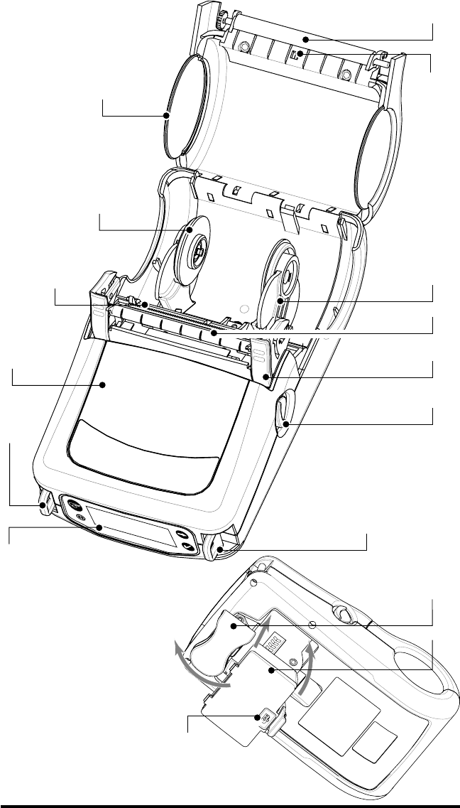
6QL 320 User’s Guide
1Platen Roller
2. Bar Sensor
3. Media Support
4. Peeler “Flip Strip”
5. Latch
6. Latch Release Lever
7. “D” Rings
8. Control Panel
9. QuickLink Module
10. Print Head
11. Media Support Disks
12. Media Cover
13. Belt Clip
14. Battery
15. Battery Charging Receptacle
1
2
3
4
5
6
7
7
8
10
11
12
13
14
15
9

QL 320 User’s Guide 7
Introduction
Thank you for choosing our Zebra QL 320 Mobile Printer. This
rugged printer is sure to become a productive and efficient addi-
tion to your workplace thanks to its innovative design. Because it’s
made by Zebra Technologies Corporation, you’re assured of
world-class support for all of your bar code printers, software, and
supplies.
• This user’s guide gives you all the information you’ll need to
operate the QL 320 printer.
• The QL 320 uses the CPL programming language. To cre-
ate and print labels using the CPL language, refer to the
Mobile Printer Programming Guide (p/n PRO-MAN) and our
Label Vista™ label creation program.
• The QL 320 can also use Zebra’s “ZPL II” programming lan-
guage if equipped with the optional memory upgrade. You
can refer to the ZPL II Program Guide (part #46530L) for
information about Zebra’s label design programming lan-
guage. If either manual was not ordered with your printer,
simply call your re-seller or Zebra Technologies Corporation
or visit the Zebra web site.
Unpacking and Inspection
Inspect the printer for possible shipping damage:
• Check all exterior surfaces for damage.
• Open the media cover (refer to “Loading the Media” in the
Getting Ready to Print section) and inspect the media com-
partment for damage.
In case shipping is required, save the carton and all packing
material.
Reporting Damage
If you discover shipping damage:
• Immediately notify and file a damage report with the ship-
ping company. Zebra Technologies Corporation is not re-
sponsible for any damage incurred during shipment of the
printer and will not cover the repair of this damage under its
warranty policy.
• Keep the carton and all packing material for inspection.
• Notify your authorized Zebra re-seller.
8QL 320 User’s Guide
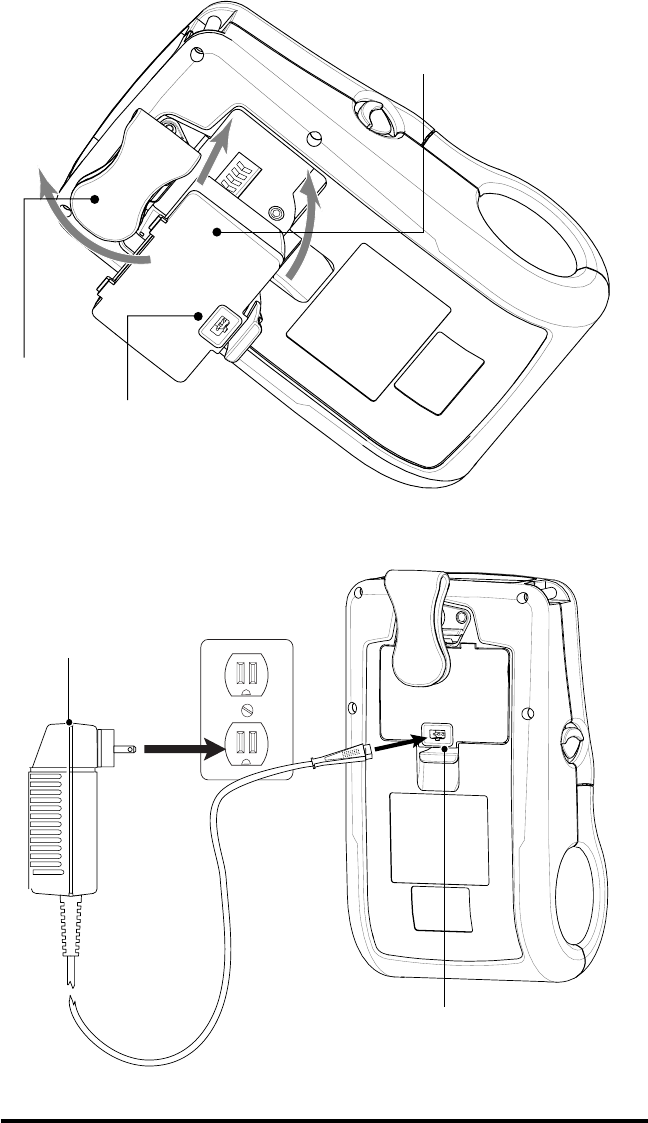
FIGURE 2
Battery
Belt Clip
Charger Jack
LI72 Charger
FIGURE 3
Charger Jack

QL 320 User’s Guide 9
Getting Ready to Print
Battery
Installing the Battery
NOTE: Batteries are shipped uncharged. Remove protective shrink-
wrap and labels from new battery packs prior to use.
1. If the printer is so equipped, rotate the Belt Clip to allow ac-
cess to the Battery compartment.
2. Insert the battery into the printer as shown in Figure 2,
3. Rock the Battery into the printer as shown until it locks in
place.
When the battery is first installed, the Control Panel indicators
may briefly turn on and then go off which indicates the battery is
not fully charged (see “Charging the Battery” below and “Operator
Controls”).
Charging the Battery
Refer to Figure 3. Your battery charger may look slightly differ-
ent from the ones illustrated.
If you are using the LI 72 battery charger:
1. Install the battery in the printer and plug the Charger into
the appropriate A.C. wall receptacle. Then insert the
charge cable into the battery charger jack.
2. The charger LED will indicate the status of the charger as
follows:
• A steady light indicates the battery is undergoing a fast
charge.
•A slow blinking light indicates the charger is in trickle mode.
The battery is ready for use.
•A rapidly blinking light indicates a problem with the battery.
The battery may have an internal short, or its charge moni-
toring circuitry may be malfunctioning. The battery should
not be used any further.
•Battery Packs may be charged either when installed in the
printer or when removed.
Do not attempt to charge batteries with the LI 72
while printing. Attempting to print while charging can
result in improperly charged batteries.
10 QL 320 User’s Guide
Loading the Media
You can operate this printer in one of two different modes: Tear-
Off or Peel-Off. Tear-Off mode allows you to tear off each label (or
a strip of labels) after it is printed. In Peel-Off mode, the backing
material is peeled away from the label as it is printed. After you
remove this label, the next one is printed.
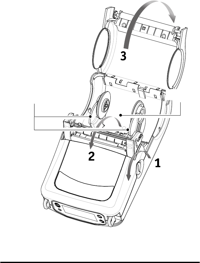
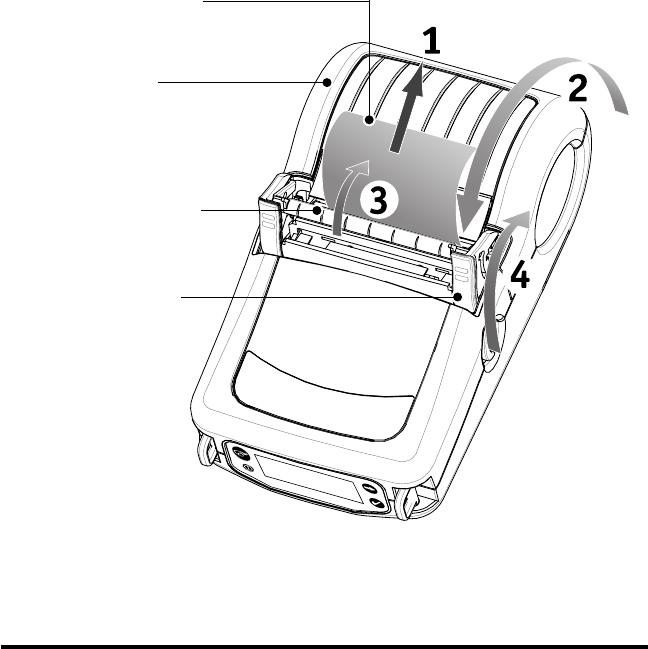
Installing the Media
1. Refer to Figure 4. Open the printer:
•Rotate the latch release levers on each side of the printer
as shown at “1” below.
The latch assembly will
flip open automatically
as shown at “2”.
•Rotate the media
Cover back as
shown at “3”, ex-
posing the media
compartment
and the adjust-
able media
supports.
FIGURE 4
Media Supports
Media
Compartment
QL 320 User’s Guide 11
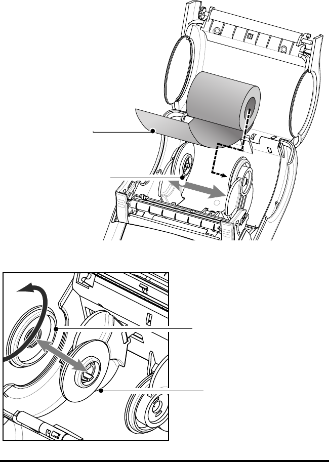
2. Refer to Figure 5. Load the media
•Determine that the core diameter of the media roll matches
the setting of the Media Disks. If it does not, adjust the me-
dia disks per Figure 6 below.
•If the media support setting is correct, pull the media sup-
ports apart, insert the roll of media between them, and let
the media supports close. Insure that the media pulls off
the core in the direction
shown in Figure 5. The
supports will adjust
themselves to the
width of the media,
and the media
should be able to
spin freely on the
supports.
continued on next page
F
IGURE 5
Media Roll
Note direction
media pulls off
the roll.
Media Disk
must match diame-
ter of Media Core.
F
IGURE 6
Media Disk set for
3/4” core (factory
default).
Remove Media
Disk, rotate 180
∞
and replace for
1.40” core
12 QL 320 User’s Guide
3. Refer to Figure 7. Close the Media Cover
•If you plan to use the printer in the tear-off mode, close the
media cover as shown at “2”, then rotate the latch assembly
as shown until it locks into place, as shown at “4”.
•If you plan to use the printer in the peel-off mode, peel a
few labels off of the media roll and pull it out of the printer
as shown at “1”. Close the media cover as shown at “2”.
Rotate the Peeler Bar until it locks into place on the latch,
as shown at “3”, then rotate the Latch as shown until it
locks into place, as shown at “4”.
•Turn on the printer or press the Feed button if the printer is
already on.
The printer will advance the media to the next label, if print-
ing labels. If you are printing on journal media, the printer
will advance a short strip of media and will then be ready
for printing.
FIGURE 7
Media Cover
Peeler Bar
Flip down after
Latch is closed if
using media in
the peel-off
mode.
Latch Assembly
Pull Media out of
Printer

QL 320 User’s Guide 13
Operator Controls
The QL 320 will come with one of two possible control panels.
The standard control panel is detailed below and in Figure 8. The
optional control panel (Figure 9) features an LCD which allows
easy display and selection of many printer functions and is de-
tailed on following pages.
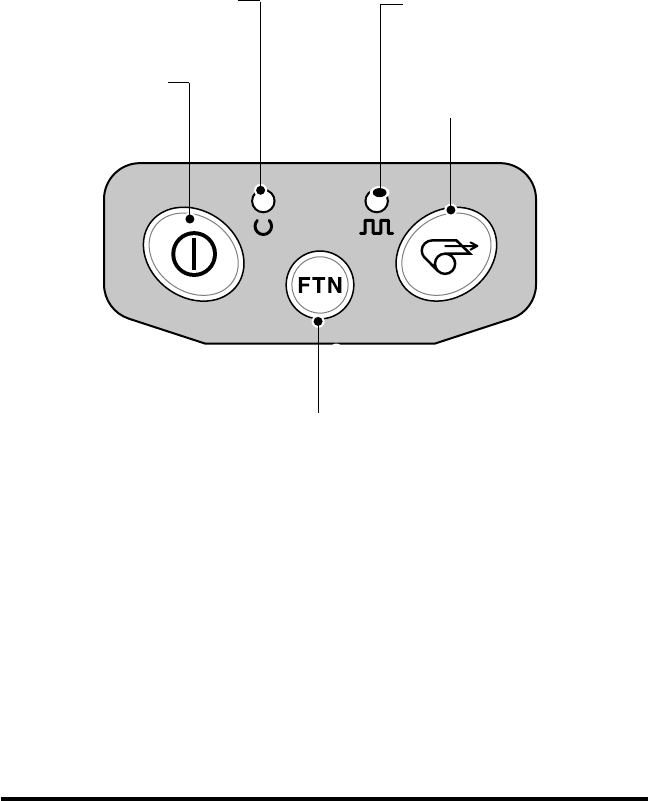
Standard Keypad
The standard keypad has three control buttons and two multi-
purpose indicators.
•The Power button turns the QL 320 on and off.
•The Feed button advances a length of media which is de-
termined by the type of media being used. Label media will
be advanced to the next gap or bar sense marker. Journal
(plain) media will be advanced a length determined by the
printer’s software.
•The Function button is controlled by a printer’s specific ap-
plication to support such functions as:
Print a battery Level reporting
Print the Local Area Network (LAN) status
Print a Short Range Radio Frequency (SRRF) status
Print a Media supply report
The green LED on the left side of the control panel indicates
the status of several printer features:
•A slowly blinking sequence indicates the printer’s battery
needs charging.
•Printers with a wireless QuickLink module installed: a quick-
ly blinking sequence indicates the printer has not estab-
lished a link to either a Local Area Network or a compatible
wireless equipped terminal.
•Printers with a wireless QuickLink module installed: A
steadily lit indicator shows that the printer has established a
wireless link, either to the LAN or to a compatible terminal.
A steadily lit green indicator on a non-wireless printer is a
power-on indicator.
The yellow LED on the right side of the control panel has two
indication conditions.
•A rapidly blinking yellow LED and a chime indicate that no
application has been loaded into the printer.
•Printers with a wireless QuickLink module installed: a rapid-
ly blinking LED indicates normal data transmission.
14 QL 320 User’s Guide
•A steadily lit yellow LED indicates an error condition. This
can be caused by one of the following:
1. The media cover is not completely closed and latched.
2. The printer is out of media.
FIGURE 8: STANDARD CONTROL PANEL
Green LED
Steady Light indicates power
on and/or established RF link.
Fast Blink indicates no RF link
(on RF equipped units only)
Slow Blink means low battery
Yellow LED
Steady Light indicates error
condition: out of media or
media cover not closed.
Fast Blink indicates RF activi-
ty (on RF equipped units only)
Fast blink with beeper indi-
cates no application loaded
Power Button
Press to turn unit on. Press
again to turn unit off
Feed Button
Press to advance the media
one blank label or a software
determined length of journal
media.
Function Button
Specific functions are under
printer application control.
QL 320 User’s Guide 15
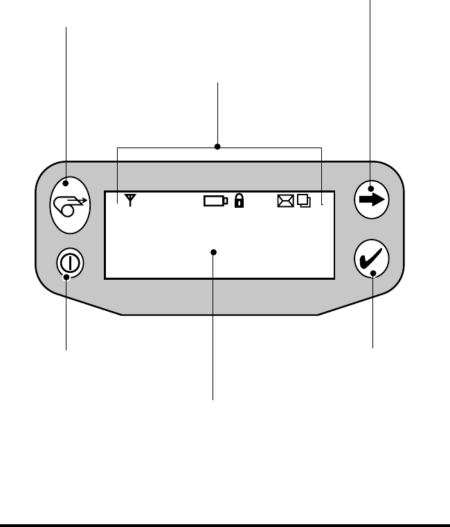
LCD Control Panel
The optional LCD control panel has buttons for the power on/off
and media feed functions just as in the standard control panel. In
addition, it has two keys which allow easy navigation and selec-
tion of menu options affecting many printer functions.
The “Scroll” button allows scrolling through the various options
and settings. The “Select” button allows selection of the option or
function displayed on the screen.
FIGURE 9: OPTIONAL LCD CONTROL PANEL
Power Button
Press to turn unit on.
Press again to turn
unit off
Feed Button
Press to advance
the media one
blank label or a
software deter-
mined length of
journal media.
Scroll Button
Press to scroll through the
menu choices on the LCD.
Select Button
Press to select a menu
choice on the LCD.
LCD
See LCD Functions Table for
an overview of menu options
Printer Status Icons
Indicates the status
of several printer
functions
16 QL 320 User’s Guide
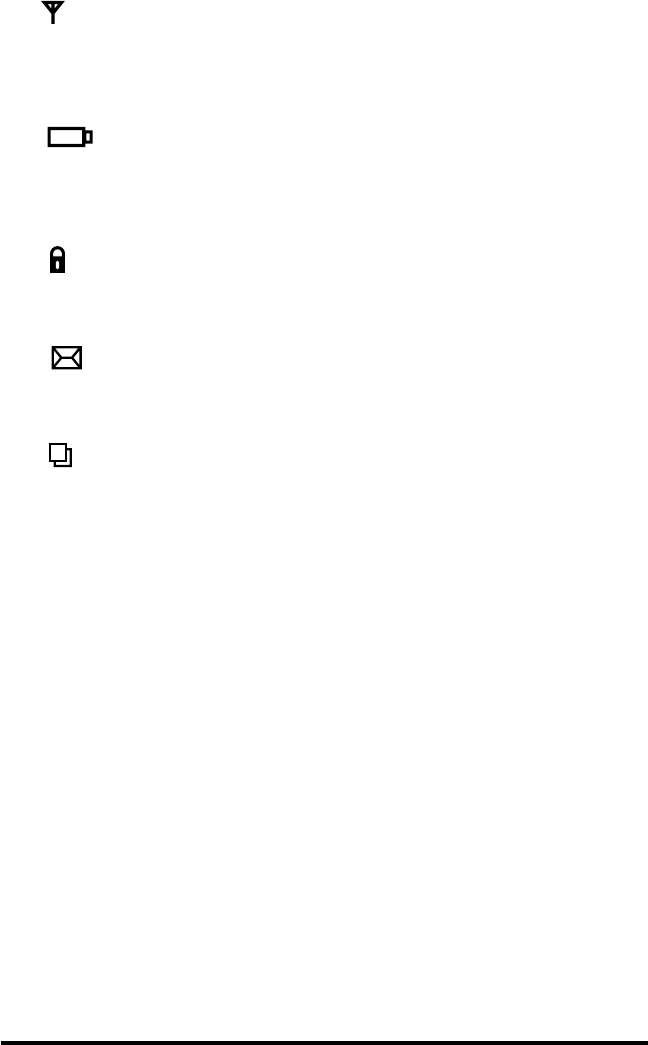
The top of the screen has a row of status icons which indicate
the state of various printer functions:
Indicates that the printer is associated with a wireless Lo-
cal Area Network (LAN). This icon is functional only with
QL 320N network printers.
A flashing icon indicates low battery status. You
should suspend any printing operations and recharge or re-
place the battery Pack as soon as is convenient.
A flashing icon indicates that the media cover is open or
not properly latched.
A flashing icon indicates that a file is being downloaded
to the printer.
A flashing icon indicates that the printer does not detect
any media. This could indicate an out of media condition,
or improperly loaded media.
In addition to the status icons, the LCD control panel can display
many of the printer’s settings and functions as text. Applications
can be written to allow the user to view and /or modify these set-
tings using the scroll and select keys on the display. Refer to the
“LCD Functions Table” on the following page for the full set of
printer features that can be made available with the LCD panel.
The LCD has a backlighting option which allows viewing of the
screen in a dark environment, or provides better contrast in a very
bright environment. Use of the display backlight will decrease the
time the printer will run between charges.
QL 320 User’s Guide 17
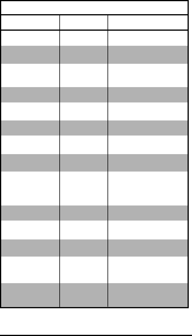
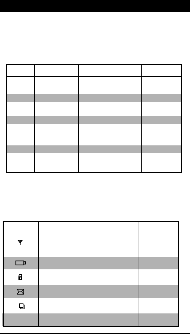
LCD Functions
Function Default setting Scroll & Select Options
Sensor Type Gap • Bar
•Gap
Print Width Factory Set • Increase (+120 dots max.)
Value • Decrease (-120 dots max.)
Baud Rate 19200 • 9600
•19200
•32400
Data Bits 8 • 7
•8
WLAN ID* Factory Set N/A
Value
Label Top 000 • Increase (+120 dots max.)
•Decrease (-120 dots max.)
Left Position 000 • Increase (+120 dots max.)
•Decrease (-120 dots max.)
LCD Contrast 0 • Increase
•Decrease
No-activity Timeout 60 sec. • 60 sec.
•5 min.
•10 min.
•30 min
•Custom*
Print Darkness 00 • Increase (+10 max.)
(Head Temperature) • Decrease (-10 max.)
Tear-off Position 00 • Increase (+120 dots max.)
•Decrease (-120 dots max.)
Media Type Label • Label
•Journal
LCD Backlight Off • On
•Off
•Momentary On w/
time delay
Factory Reset No • No
(Resets all to • Yes
factory set values)
* Some parameters, such as the WLAN ID number and non-standard no-activi-
ty time out values can be set using a PC running Zebra’s Label Vista label
creation program and a data cable link to the printer.

18 QL 320 User’s Guide
Verify the Printer Is Working
Before you connect the printer to your computer or portable data
terminal, make sure that the printer is in proper working order.
You can do this by printing a configuration label using the “two key
reset” method. If you can’t get this label to print, refer to “Trouble-
shooting”.
Printing a Configuration Label
1. Turn the printer off. Load the media compartment with jour-
nal media (media with no black bars printed on the back)
2. Press and hold the Feed Button.
3. Press and release the Power button and keep the Feed but-
ton pressed. When printing starts, release the Feed button.
The unit will print a line of interlocking “x” characters to insure
all elements of the print head are working, print out the version of
software loaded in the printer and then print two reports.
The first report indicates model, ROM version, serial number,
baud rate, etc. The second report prints out more detailed infor-
mation on the printer’s configuration and parameter settings. If no
second report appears, there is no application loaded. (see the
Troubleshooting Section for a further discission on the how to use
the configuration label as a diagnostic tool.)
Connecting the Printer
The printer must establish communications with a host terminal
which sends the data to be printed. Communications occur in four
basic ways:
•By a cable between the printer and its host terminal
•Linking to a host terminal via Infrared (usually by means of
the industry standard IrDA protocol)
•By means of a Short Range Radio Frequency (SRRF) link.
•By means of a wireless LAN (Local Area Network). This
applies to QL 320N Network Printers only.
QL 320 User’s Guide 19
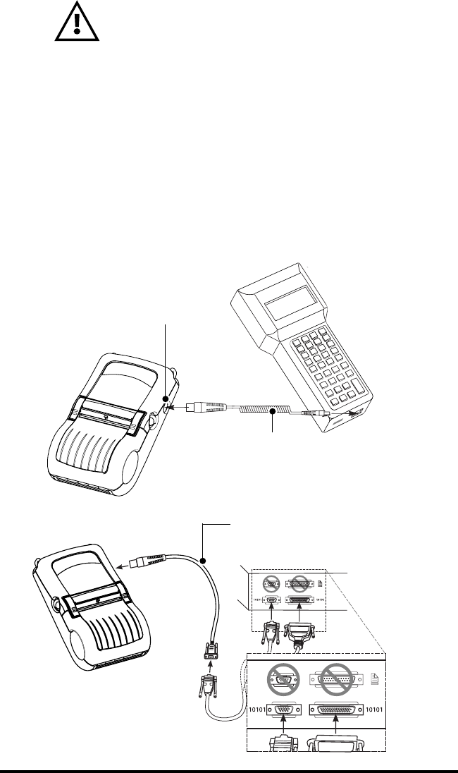
Cable Communications
CAUTION. The power should be turned off
before connecting or disconnecting the
communications cable.
All QL 320 printers can communicate by cable; the specific ca-
ble supplied with your printer will vary with the host terminal. The
8- pin circular connector on your communications cable plugs into
the serial communications port on the side of the QL 320 printer.
It is keyed to assure correct alignment; do not try to force it if it
does not plug in. The other end of the cable must be plugged into
the host terminal as shown in Figure 10, or to a serial port on a
computer (Figure 11.) Communications between the terminal and
the printer are controlled by the applications running on the termi-
nal and the printer.
FIGURE 11
Communications Cable to Terminal
Part number varies. Refer to Appendix A.
QL 320
Communications Port
FIGURE 10
Serial Communications Cable to Computer
Refer to Appendix A for part numbers.
20 QL 320 User’s Guide
IR Communications
Printers equipped for infrared (IR) communications are identified
by a small “IR” logo on the unit’s label. IR allows wireless commu-
nications between the printer and the host terminal. IR units can
also communicate with a cable as detailed above, however, IR
functions are disabled when the cable is plugged in. QL 320 units
with the IR option can be configured to conform to the standard
IrDA communications protocol
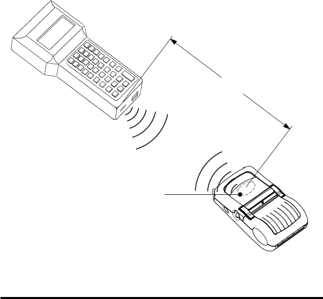
Linking a Printer to an IrDA Host
IrDA compliant terminals will automatically initiate communica-
tions to the printer. First insure that there is a direct line of sight
between the printer and the terminal that will be sending data. The
IR window on the front of the QL 320 must face the corresponding
window on the terminal to properly send and receive signals. An
IrDA compliant terminal will seek out any linkable devices and es-
tablish communications between them, even turning the printer on
if necessary.
1M (39”)
F
IGURE 12
Area of IR Window

QL 320 User’s Guide 21
SRRF Communications
Both the printer and the device it communicates with must follow
either the Bluetooth standard or Zebra’s proprietary SRRF proto-
col. The communications protocol is determined by the specific
QuickLink module installed in the printer.
Printers equipped for short range radio frequency communica-
tions (SRRF) allow wireless communication with their host termi-
nals from any direction. Reliable transmission distances will vary
but usually exceed 1m. (39”) under worst conditions. SRRF print-
ers can be identified by reading the printer’s model number label
on the front of the unit, which will show the radio module’s identifi-
cation number and/or its operating frequency. QL 320 printers
equipped with a Bluetooth wireless module will have the Bluetooth
logo on the model number label.
Zebra SRRF Network Overview
Zebra’s short range RF network operates as a collection of
linked pairs of terminals and printers. There is no base station or
centralized control; control of the network is distributed across the
entire network.
Before SRRF operation can begin, the QL 320 must be “linked”
to a terminal with a compatible short-range radio. Linking means
that addresses are exchanged between the terminal and the print-
er. Once linked, the terminal and the printer become a “linked pair”
and communicate exclusively with each other. The terminal and
the printer can be turned on and off without affecting the link; it re-
mains valid until another link is deliberately created. Thus it is not
necessary to perform a link every time that the equipment is used.
So long as the linked pair is kept together, they remain linked in-
definitely. If the linked pair is not stored together, then the terminal
and printer selected should be linked prior to use.
Multiple linked pairs can be operated in close quarters and each
terminal will only communicate with its linked printer. Each SRRF
radio module has a unique device address (terminal or printer),
based on the device serial number.
Linking From the Terminal to the Printer
The linking operation can be activated from either the terminal
or the printer. If the terminal has a scanner available, then the bar-
coded serial number on the back of every printer can be scanned
and used to establish the printer’s unique address. Once the print-
er’s address is established, the terminal can then initiate a link to
that printer. If no scanner is available the user can manually enter

22 QL 320 User’s Guide
the serial number of the printer; however, this method is not rec-
ommended. The terminal can only capture the desired printer us-
ing this type of link.
The terminal must be programmed to guide the user through
scanning the printer serial number bar-code, then execute an al-
gorithm which converts the serial number into an address. Zebra
can provide C source code to licensed OEM customers that han-
dles the conversion from serial number to address.
Linking From the Printer to the Terminal
When no scanner is available, and/or no additional software is
to be written for the terminal, then the linking operation can be ini-
tiated solely by the printer.
In this procedure the printer broadcasts a message seeking an
available terminal. If a terminal “hears” the broadcast and is avail-
able, it will respond by linking to the printer.
To insure a secure link, the user must perform the link operation
far enough away from other operating terminals so that the printer
does not inadvertently capture some other user’s terminal. Any
other terminal that hears the broadcast message from the printer
may try to link to it, therefore you should insure that only one ter-
minal is within broadcast range Feedback is available from the
printer as to the outcome of the link operation.

QL 320 User’s Guide 23
Bluetooth™ Networking Overview
Exposure to Radio Frequency Radiation
The radiated output power of this internal wireless
radio is far below the FCC radio frequency exposure
limits. Nevertheless, this Bluetooth radio must be used
in such a manner that the antenna is 2.5 cm or further
from the human body.
The radio and antenna are mounted internally in this
printer in such a way that, when the printer is used in a
standard configuration (belt clip, soft case, shoulder
strap), the 2.5 cm distance from the users body will be
met. Do not use the printer in an unauthorized manner.
The internal wireless radio operates within guidelines
found in radio frequency safety standards and
recommendations. The level of energy emitted is far
less than the electromagnetic energy emitted by
wireless devices such as mobile phones.
“Bluetooth” is a worldwide standard for the exchange of data be-
tween two devices via radio frequencies. Bluetooth radios are rel-
atively low powered to help prevent interference with other
devices running at similar radio frequencies. This limits the range
of a Bluetooth device to about 10 meters (about 32 feet).
In order to exchange data, two Bluetooth enabled devices must
establish a connection. Bluetooth software is always running in
the background, ready to respond to connection requests. One
device (known as the
master
or the
client)
must request a connec-
tion with another. The second device (the
slave
or the
server
)
then accepts or rejects the connection. A Bluetooth enabled QL
320 will normally act as a slave, but in theory any Bluetooth de-
vice can be either a master or a slave. This miniature network is
sometimes referred to as a “piconet” and in theory can consist of
several Bluetooth enabled devices.
Each Bluetooth QL 320 has a unique Bluetooth Device Address
(BDA) loaded into its Quick Link module when manufactured.
A Typical Bluetooth Connection Sequence
In this simplified sequence “Joe’s Terminal” is a Bluetooth-aware
hand held terminal running an application that needs access to a
printer.
1. Joe’s Terminal performs a search of its “piconet” (a Device In-

24 QL 320 User’s Guide
quiry) and determines that there are four Bluetooth devices in the
vicinity.
2. Joe’s Terminal queries each of the four nearby devices to de-
termine which services they provide (a Service Discovery). The
Bluetooth enabled QL 320 “Sandy’s Printer” offers the printing ser-
vice.
3. Joe’s Terminal sends a print connection request to Sandy’s
Printer.
4. Sandy’s Printer evaluates the request and determines that
Joe’s Terminal is permitted to use the print service,
but only if the
correct password is submitted
.
5. Sandy’s Printer queries Joe’s Terminal for the password (Au-
thentication).
6. Joe’s Terminal returns the correct password and the print con-
nection is established.
7. After Joe’s Terminal is finished printing it disconnects with
Sandy’s Printer. (Some Bluetooth services disconnect automati-
cally, others must be closed manually.)
There are several layers of security in the Bluetooth system, so
this sequence may not be a completely accurate representation of
how your printer may function in a Bluetooth environment. For the
most part, communications using the Bluetooth protocol are initi-
ated and processed without any operator intervention, much like
the IrDA system described previously.

QL 320 User’s Guide 25
Wireless Local Area Network (WLAN)
WARNING: Use of the QL 320 will result in
exposure to Radio Frequency radiation. To conform to
FCC RF exposure requirements the printer must be
used only in the intended orientation and in the
intended manner.
Printers equipped for Wireless Local Area Network (WLAN)
communications using the industry standard 802.11 or 802.11b
protocols are known as QL 320N Printers. These printers allow
wireless communication as a node within a local area network,
and its wireless capabilities allow communications from any point
within the LAN’s perimeter. Methods of establishing communica-
tions to the QL 320 will vary with each LAN application.
QL 320N printers can be identified the model number on the
front of the unit.
The QL 320N is designed for use with either a shoulder strap
and a specially designed soft case, or with a belt clip. The printer
should be oriented on the operator’s hip so that printed material is
transported
away
from the operator.
When the QL 320N is used as designed, either the printer’s soft
case or the belt clip will allow use of the printer in the manner
mandated by the FCC.

26 QL 320 User’s Guide
Setting Up the Software
The QL 320 uses Zebra’s CPL Programming language which
was designed for mobile printing applications. CPL is fully de-
scribed in the Mobile Printing Systems Programming Manual,
which is available in Portable Document Format (.pdf) either on-
line at Zebra’s website, or on a 3.5” floppy disk (part number
DISK-PROMAN).
You can also use Label Vista™, Zebra’s Windows™ based label
creation program which uses a graphical interface to create and
edit labels in the CPL language. Label Vista is available either on-
line at Zebra’s website, or on a CD (part number AC15065-1).
The QL 320 with its optional memory upgrade can support ZPL
II, the programming language used by Zebra desktop printers. To
use ZPL II, refer to the ZPL II Programming Guide. If you choose
to use a third party label preparation system, follow the installation
instructions included in the package.
QL 320 User’s Guide 27
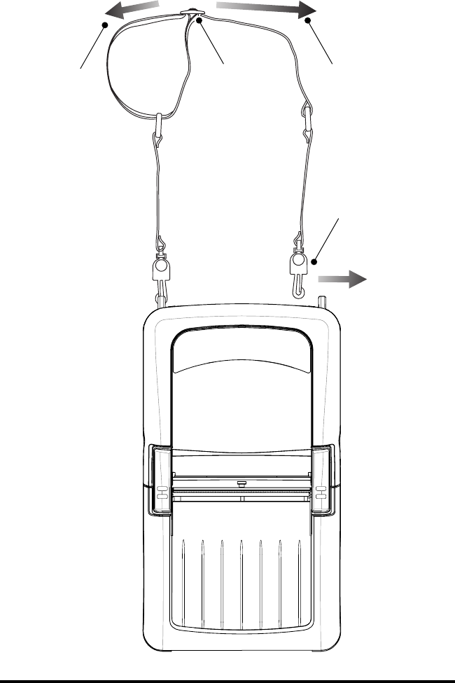
Adjustable Shoulder Strap
Refer to Figure 14, below.
Snap each end of the shoulder strap into the “D” rings in the top
of the printer. Slide the buckle away from or towards the printer
until you achieve the desired length.
FIGURE 14
Hold Buckle Pull Strap here
to lengthen
Pull Strap here
to shorten
Snap in to “D”
rings on
printer
28 QL 320 User’s Guide
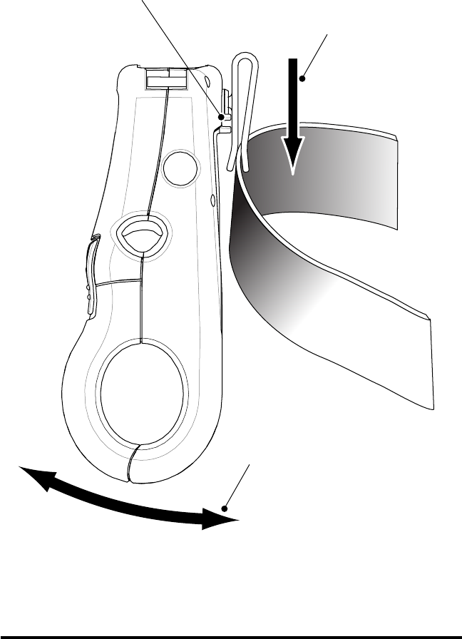
Belt Clip
If the QL 320 is equipped with a belt clip, hook the clip over your
belt, and ensure that the clip is securely attached to the belt. The
belt clip will pivot to allow you to move freely while wearing the
printer.
FIGURE 15
Clip printer to
belt
Printer can
pivot freely
Dress cables
through this
slot

QL 320 User’s Guide 29
Preventive Maintenance
WARNING: To avoid possible personal injury or
damage to the printer, never insert any pointed or sharp
objects into the printer.
Extending Battery Life
•Never expose the battery to direct sunlight or temperatures
over 104∞ F (40∞ C).
•Always use a Zebra charger designed specifically for Li-
thium-Ion batteries. Use of any other kind of charger may
damage the battery.
•Choose the media that is easiest to “burn.” An authorized
Zebra re-seller can help you determine the optimum media
for your application.
•If you print the same text or graphic on every label, consid-
er using a pre-printed label.
•Choose the correct print darkness, and print speed for your
media.
•Use software handshaking (XON/XOFF) whenever possi-
ble.
•Select Tear-Off mode whenever possible (Peel-Off mode
uses more power).
•If your printer has the optional LCD display: Use the display
backlight only when necessary. Turn it off whenever it is not
needed. The LCD backlight consumes a great deal of pow-
er.
•Pull the battery out of the printer if the printer won’t be used
for a day or more and you’re not performing a maintenance
charge.
•Consider purchasing an extra battery.
•Remember that any rechargeable battery will lose its ability
to maintain a charge over time. It can only be recharged a
finite number of times before it must be replaced.
30 QL 320 User’s Guide
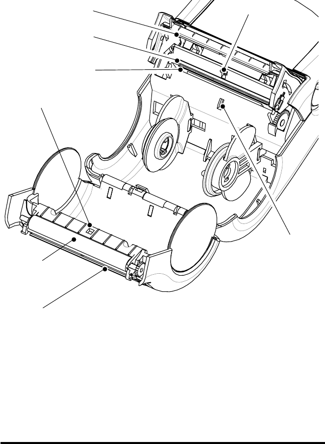
FIGURE 16
Printhead
Elements
Peeler Bar Rollers
Peeler Bar
Platen
Tear Bar
Label
Presence
Sensor
Bar Sensor
Gap Sensor
QL 320 User’s Guide 31
Cleaning
CAUTION.- Use only the cleaning agents
indicated. Zebra Technologies Corporation will not be
responsible for damage caused by any other cleaning
materials used on this printer.
Never use any sharp objects on the printer mechanism
as it could damage the print head. Use only the
cleaning pen supplied with the printer or a cotton swab
saturated with alcohol for cleaning the printer.
Printhead
(Figure 16)
Use the supplied cleaning pen or 70%
isopropyl alcohol on a cotton swab to
clean the print elements from end to
end (the print elements are located in
the thin gray line on the printhead).
If print quality has not improved after
performing this procedure, try cleaning
the printhead with a Cleaning Pad.
This specially prepared material
removes contamination buildup without
damaging the printhead. Refer to
Appendix C for more information.
Platen Roller
(Figure 16)
Rotate the platen roller and clean it
thoroughly with the cleaning pen or
70% isopropyl alcohol and a cotton
swab.
Units with linerless platens: No
cleaning is necessary.
Do not use
alcohol on linerless platens!
Peel bar
(Figure 16)
Clean thoroughly with the cleaning pen
or 70% isopropyl alcohol and a cotton
swab.
Tear bar
(Figure 16)
Clean thoroughly with the cleaning pen
or 70% isopropyl alcohol and a cotton
swab.
Exterior Water-dampened cloth
Area Method Interval
Interior
(Figure 16)
As needed
Brush/air blow. Insure the Bar
Sensor, Gap Sensor and Label
Present Sensor windows are free of
dust.
After every five
rolls of media (or
more often, if
needed)
Linerless media
requires more
frequent
cleaning.
32 QL 320 User’s Guide
Troubleshooting
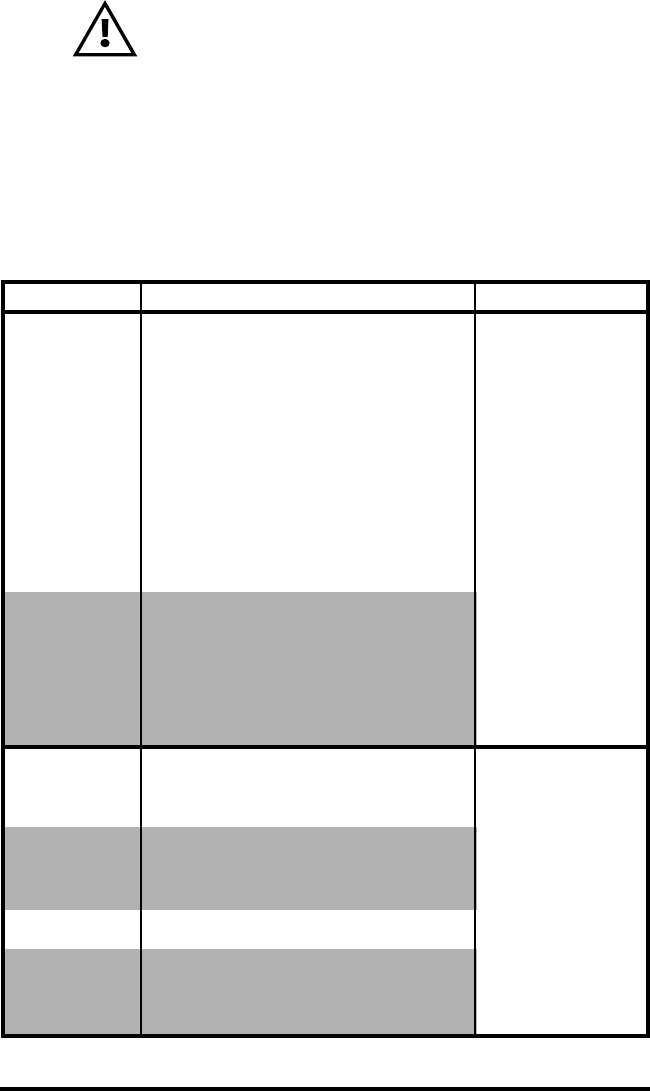
Standard Control Panel
If the printer is not functioning properly, refer to the chart below
to find the state of the two LEDs on the Control Panel. Then refer
to the Troubleshooting topic referenced in the chart to resolve the
problem.
Green LED Yellow LED Indication Ref. to Topic
Steady Off Normal Operation, n/a
and/or RF Link established
Off Off Power Off 1
Fast Blink Off No RF Link 6, 11
Slow Blink Off Low Battery 3, 6, 7
Steady Steady Out of media, or 9, 11
Media Cover not closed
Steady Fast Blink Normal RF activity 8
Steady Fast Blink, No application 8
Beeper Sounds
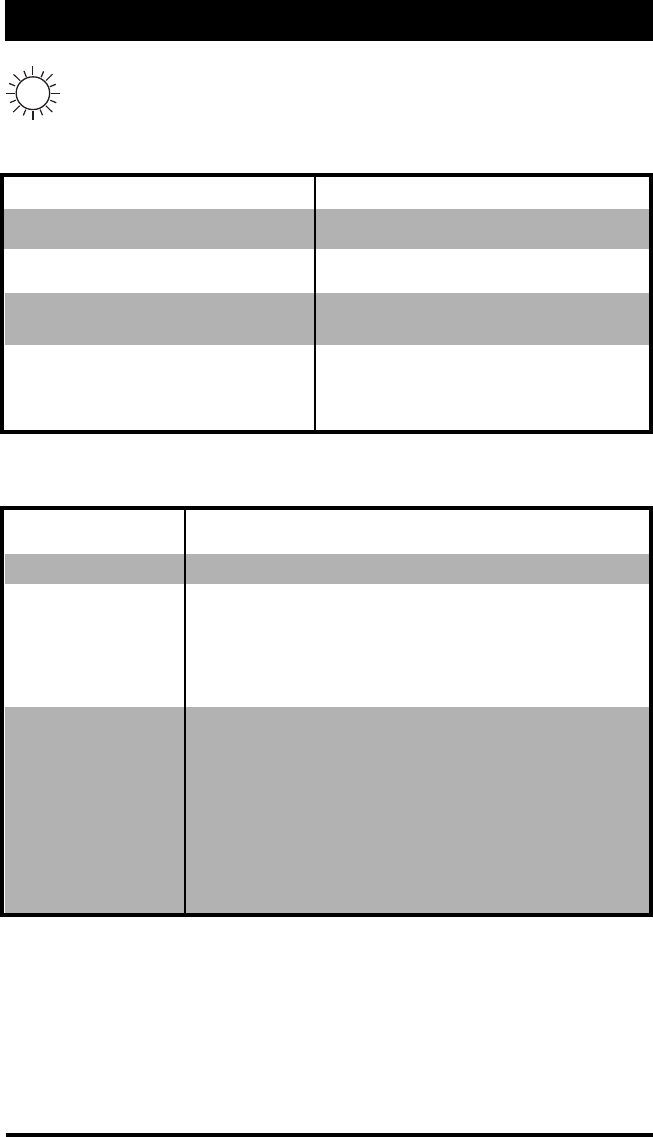
Optional LCD Control Panel
The top of the display shows several icons which indicate vari-
ous printer functions. Check the indicator status, then refer to the
Troubleshooting topic referenced in the chart to resolve the prob-
lem.
Status Icon Condition Indication Ref. to Topic
Steady RF Link established n/a
Off No RF Link 6
Flashing Low Battery 3, 6, 7
Flashing Head latch not closed 9, 11
Flashing Printer is receiving a file 8
Flashing Out of media, 9, 11
Blank Screen n/a No application 1,13

QL 320 User’s Guide 33
Troubleshooting Topics
1. No power
•Check that battery is installed properly
•Recharge or replace battery as necessary.
2. Media does not feed:
•Be sure print head is closed and latched.
•Check spindle holding media for any binding.
•If unit is equipped with label presence sensor:
Insure most recently printed label is removed.
Also insure label sensor is not blocked.
3. Poor or faded print or flashing:
•Clean print head.
•Check battery and recharge or replace as necessary
•Check quality of media.
4. Partial/missing print:
•Check media alignment
•Clean print head.
•Insure printhead is properly closed and latched.
5. Garbled print:
•Check baud rate.
6. No print:
•Check baud rate
•Replace battery
•Check cable to terminal
•Establish RF Link (Wireless units only) or restore LAN
associativity (QL 320N models only)
•Invalid label format or command structure — put printer in
Communications Diagnostic (Hex Dump) Mode to diagnose
problem.
7. Reduced battery life
•Check battery date code — if battery is one to two years old,
short life may be due to normal aging.
•Recondition battery.
•Replace battery.
8. Yellow error light or flashing:
•No application or application corrupted: reload program.
•If using wireless communications: flashing indicator is normal
while data is being transmitted or received.
continued on next page

34 QL 320 User’s Guide
Troubleshooting Tests
Printing a Configuration Label
To print out a listing of the printer’s current configuration follow
these steps:
9. Yellow error light always on, or flashing:
•Check media is loaded and print head is closed and
securely latched.
10. Skips labels:
•Check media for top of form sense mark or label gap.
•Check that the maximum print field has not been exceeded on
label.
•Insure bar/ or gap sensor is not blocked or
malfunctioning
11. Communication Error:
•Check media is loaded, head is closed and error
light is off.
•Check baud rate.
•Replace cable to terminal.
12. Label Jam:
•Open head release latch and media cover.
•Generously apply alcohol to printer in area of
jammed label.
13. Blank LCD Screen (only for units with optional LCD
control panel)
•No application loaded or application corrupted: reload program.
1. Turn the printer off. Load the media compartment with jour-
nal media (media with no black bars printed on the back)
2. Press and hold the Feed Button.
3. Press and release the Power button and keep the Feed but-
ton pressed. When printing starts, release the Feed button.
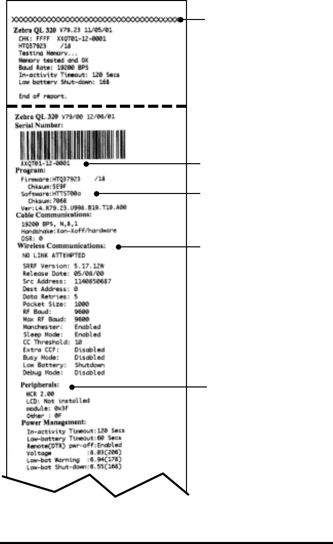
The printer will generate a configuration label as shown on Fig-
ures 17 and 17a :
QL 320 User’s Guide 35
Unit Serial Number
Application Number
End of First Report
Print Head Test
Report appears only on
units with wireless options
installed.
Units with no wireless
options will print an empty
line and resume the report.
Peripherals installed: In this
example the LCD display
option is not installed.
F
IGURE 17
Sample Configuration Label
continued on next page
36 QL 320 User’s Guide
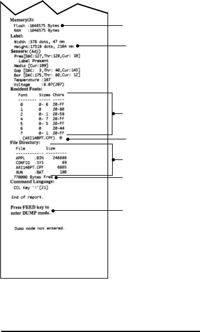
Flash Memory Size
Maximum Label Size
Files Loaded in Printer
Memory (will include Pre-
scaled or Scalable Fonts)
Amount of Memory
Available
Resident Fonts
Instructions on entering
Communications
Diagnostics (Dump) Mode.
Pre-scaled font (.cpf) listed
separately
F
IGURE 17A

QL 320 User’s Guide 37
Communications Diagnostics
If there’s a problem transferring data between the computer and
the printer, try putting the printer in the Communications Diagnos-
tics Mode (also referred to as the “DUMP” mode). The printer will
print the ASCII characters and their and their text representation
(or the period ‘.’, if not a printable character) for any data received
from the host computer
To enter Communications Diagnostics Mode:
1. Print a configuration label as described on pg. 34.
5. At the end of 2nd diagnostics report, the printer will print:
“Press FEED key to enter DUMP mode”.
6. Press the FEED key. The printer will print: “Entering DUMP
mode”.
Note: If the FEED key is not pressed within 3 seconds, the printer will print “DUMP
mode not entered” and will resume normal operation.
7. At this point, the printer is in DUMP mode and will print the
ASCII hex codes of any data sent to it, and their text repre-
sentation (or “.” if not a printable character).
Additionally, a file with a “.dmp” extension containing the ASCII
information will be created and stored in the printer’s memory. It
can be viewed, “cloned” or deleted using the Label Vista applica-
tion. (Refer the Label Vista documentation for more information.)
To terminate the Communications Diagnostics Mode and return
the printer to normal operations:
1. Turn the printer OFF.
2. Wait 5 seconds.
3. Turn the printer ON.
Calling the Help Desk
If the printer fails to print the configuration label, or you encoun-
ter problems not covered in the Troubleshooting Guide, contact
the Help Desk. Help Desk addresses and phone numbers for
your area can be found in Appendix D of this manual. The Help
Desk will need the following information:
•Model number/type (e.g. QL 320)
•Unit serial number (Found on the large label on the back of
the printer, also found in the configuration label printout))
•Product Configuration Code (PCC) (15 digit number found
on the small label on the back of the unit)
38 QL 320 User’s Guide
Specifications
NOTE.- Printer specifications are subject to change without notice.
Printing Specifications
Print Density 203 dots/inch (8 dots/mm)
Print Width Up to 2.9“ (71.2 mm)
Print Speed 4” per second (101.6 mm per second)
Print Head Life, 1,964,160” (50 Km) nominal
calculated
Distance from .571” (14.5 mm)
Print Element 116 dots
to Top of Form
Memory/Communications Specifications
Flash Memory 1 MB flash (standard); 2MB flash (optional)
SRAM Memory 1MB SRAM (standard); 2 MB SRAM (optional)
Standard RS-232 serial port (8 Pin circular DIN connector)
Communications Configurable Baud rate (from 9600 to 57.6 Kbps),
parity and data bits.
Software (X-ON/X-OFF) or hardware (DTR/STR)
communication handshake protocols.
Infrared wireless link (meets IrDA 1.1 communications
specifications) 2,400 to 115,200 Baud rate
Optional Wireless Bluetooth compatible 2.4 GHz SRRF link
Communications
Optional SRRF frequencies of 916 MHz and 2.4 GHz per
Zebra proprietary wireless protocol.
Optional wireless LAN capabilities comply with 802.11 and
802.11b protocols
QL 320 User’s Guide 39
Label Specifications
Label/Tag Width 1.5" to 3.1" (38.1 mm to 78.4 mm)
Max. Label/ 16" (406.4 mm) with standard memory
Tag Length
Inter-label Gap. .08" to .16" (.12" preferred)
2 mm to 4 mm (3 mm preferred)
Label/Tag Thickness .0025” to .0065” (.064 mm to .165 mm)
Label Roll Size:
Max. Diameter 2.625" (66.7 mm) O.D.
Inner Core .75" (19 mm) std, 1.38” (35.05 mm) optional
Diameter Use Zebra-brand direct thermal media that is outside
wound. Media may be reflective (black mark) sensing or
transmissive (gap) sensing, die-cut, continuous or
linerless.
For die-cut labels, use only full auto dies.
The reflective media black marks should extend past
Media Requirements the centerline of the roll.
Minimum Black Mark Dimensions:
Mark width: 0.5” (12.7mm) perpendicular to the edge of
the media, centered within the width of the roll.
Mark length: 0.094” (2.4 mm) parallel to the edge of the
media.
Font/Bar Code Specifications
Fonts Available Five resident scalable and rotatable fonts available
from 12-48 pt.
Downloadable pre-scaled fonts via Label Vista™
software
Optional international character sets
Codabar
UCC/EAN 128
Code 39
1D Bar Codes Available Code 93
EAN 8/JAN 8, 2 and 5 digit extensions
EAN 13/JAN 13, 2 and 5 digit extensions
lnterleaved 2 of 5
MSI/Plessey
FIM/POSTNET
UPC-A, 2 and 5 digit extensions
UPC E, 2 and 5 digit extensions
2D Bar Codes Available MaxiCode
PDF 417
Rotation Angles 0∞, 90∞, 180∞, and 270∞
40 QL 320 User’s Guide
Physical/Environmental/Electrical Specifications
Weight
w/ battery 1.65 lbs. (.75 kg. )
excluding media.
Temperature
Operating 5∞ to 122∞ F (-15∞ to 50∞ C)
Storage -13∞ to 158∞ F (-25∞ to 70∞ C) Range
Relative Humidity
Operation 10% to 80% (non-condensing)
Storage 10% to 90% (non-condensing)
Electrical Battery: 7.4V Lithium-Ion
Charger: External battery charger, 120-230 VAC
depending on model selected.
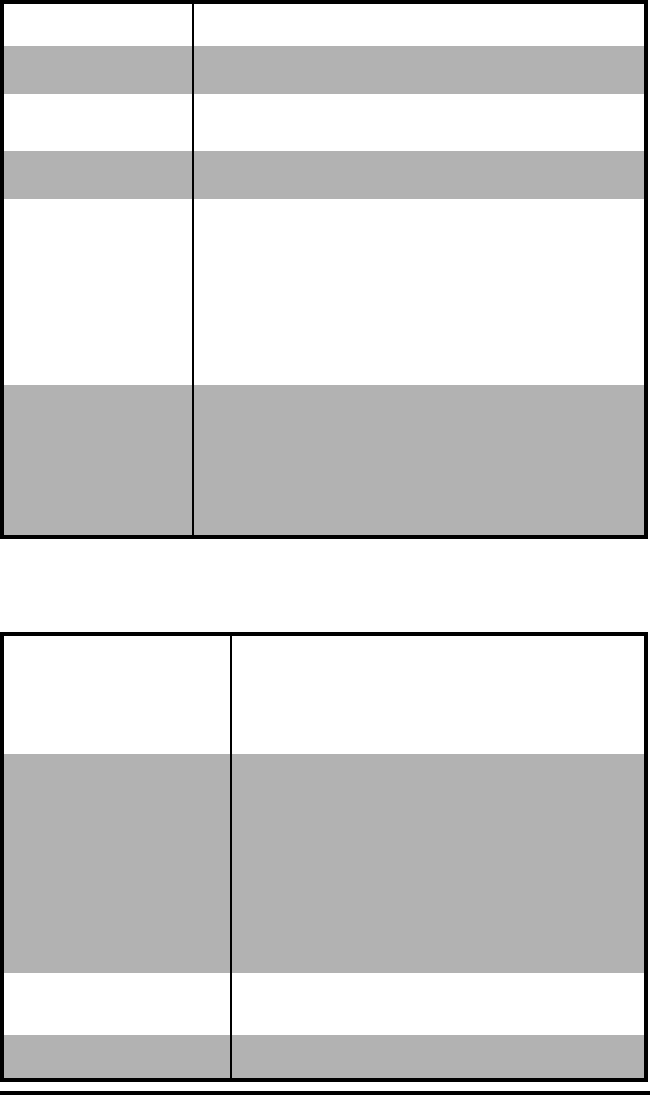
FIGURE 18 OVERALL DIMENSIONS
3.1”
[78.7 mm]
3.9”
[97.9 mm]
8.0”
[203.2 mm]
4.60”
[116.8 mm]
8.3”
[210.2 mm]
QL 320 User’s Guide 41
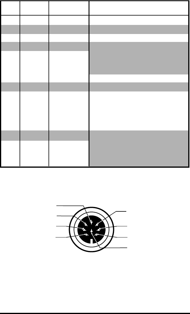
Communications Port
Signal
Pin# Name Type Description
1RXD input Receive Data
2TXD output Transmit Data
3CTS input Clear To Send from host
4RTS output Request To Send
set high when printer
is ready to accept command
/data
5GND Ground
6NCNo Connect
7DSR input Data Set Ready
low to high transition turns
printer on, high to low
transition turns printer off
(if enabled)
8DTR output Data Terminal Ready
set high when printer is on
(set to battery voltage for
“S” versions)
8
7
6
4
2
1
5
3
FIGURE 19 COMMUNICATIONS PORT
(8 pin Circular DIN)
Agency Approvals
•FCC Part 15 Subpart B Class A Electromagnetic Radiation
Standard
•Built to UL, CUL and TUV standards
•EN50082-1 International lmmunity Standard
•EN55022 Class B European Electromagnetic Radiation
Standard
Accessories
•Adjustable shoulder strap
•Protective soft case
•Extra battery packs
•120-230 VAC battery charger
•Desk Mount
•Data cables
For details, call your authorized Zebra re-seller.
QL Series User’s Guide Appendices 43
Appendix A
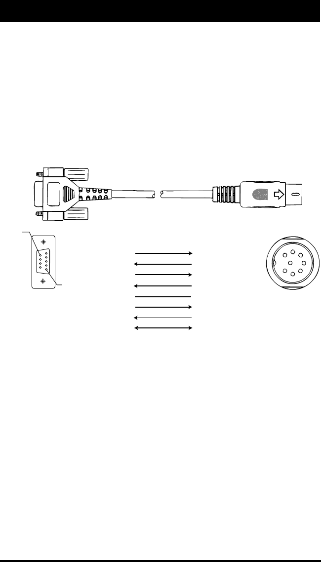
Interface Cables
Pin 1
Pin 9
DB-9 Pin
Female Plug
(to P.C.)
8 Pin
Male Plug
(to printer)
(TXD)
(RXD)
(RTS)
(CTS)
(GND)
(DTR)
(DSR)
Shield
(RXD)
(TXD)
(CTS)
(RTS)
(GND)
(DSR)
(DTR)
Shield
3
2
7
8
5
4
6
1
2
3
4
5
7
8
14
6
735
82
PC Signals Printer Signals
Part Number ´BL11757-000; 8-Pin DIN to 9-Pin DB PC Cable
This part is also available as a coiled cable under Part Number
BL15063-1.
For Use With a Personal Computer
44 QL Series User’s Guide Appendices
Appendix A
INTERFACE CABLES
Cable Cord Terminal Printer
Terminal Part Number Lgth/Type Connector Connector Notes
COMPSEE
Apex II BL12093-3 8’ Coiled RJ45 8 Pin DIN
LXE
MX1,MX3 BL17757-000 6’/Straight 9 Pin DB 8 Pin DIN
1380,1390,1590 BL17757-000 6’/Straight 9 Pin DB 8 Pin DIN
2325 BL12093-1 8’/Coiled RJ45 8 Pin DIN Power On/Off (+5V)
NORAND
RT1100/1700 Series BL11537-1 8’ /Coiled 6 Pin MinDIN 8 Pin DIN Over-molded
RT1100/1700 Series BL11537-2 12’/Coiled 6 Pin MiniDIN 8 Pin DIN Over-molded
RT5900 Series BL12803-1 8’ /Coiled 15 Pin D-Sub 8 Pin DIN
RT1100/1700 Series BL12804-1 8’ /Coiled 6 Pin MiniDIN 8 Pin DIN -Locking
RT1100/1700 Series BL13298-1 8’ /Coiled 6 Pin MiniDIN 8 Pin DIN Over-molded Auto ON/OFF
RT1100/1700 Series BL13309-1 8’ /Coiled 6 Pin Mini DIN 8Pin DIN Auto ON/OFF
6400 BL11757-000 6’/Straight 9 Pin DB 8 Pin DIN
SYMBOL
PDT3300 Series BL11391-000 8’ /Coiled DB25 male 8 Pin DIN
PDT4100 Series BL11757-000 6’ /Straight 9 Pin DB Fem. 8 Pin DIN Must be used with Symbol RS232
Adapter - Symbol PN#25-12059-01
PDT3100/3500 BL12093-1 8’ /Coiled RJ45 8 Pin DIN a. Power On/Off (+5V) b. Used for the
/6100 Series Percon Falcon
PDT3100 Series BL12093-2 8’ /Coiled RJ45 8 Pin DIN Power On/Off (DTR Line)
QL Series User’s Guide Appendices 45
Appendix A
INTERFACE CABLES (continued)
Cable Cord Terminal Printer
Terminal Part Number Lgth/Type Connector Connector Notes
SYMBOL (CONT.)
SPT1700 Series BL15483-1 9’ /Coiled Cradle 8 Pin DIN No Power On/Off (DTR Line)
SPT2700 Series BL15482-1 9’ /Coiled Cradle 8 Pin DIN Power On/Off (DTR Line)
LRT/LDT3800 Series CC11371-3 6’ /Coiled PIM Optical 8 Pin DIN “S” Printers Only
LRT/LDT3800 Series CC11371-14 6’ / Coiled PIM Optical 8 Pin DIN “S” Printers Only
(2 Way)
LRT/LDT3800 CC11371-14 6’ / Coiled PIM Optical 8 Pin DIN “S” Printers Only
& 6800 Series
LRT/LDT3800 CC11371-15 6’ / Coiled PIM Optical 8 Pin DIN “S” Printers Only
& 6800 Series
TEKLOGIC
7030 ILR BL13285-2 Coiled 36 Pin IDC Fem 8 Pin DIN
7025 ILR BL13285-1 Coiled 15 Pin DB male 8 Pin DIN
TELXON
960 BL11122-1 8’ /Coiled RJ45 8 Pin DIN
960SL Adapter CC13711-1 n/a n/a n/a
for BL11122-1
960 (BL11122-1) CP74005 n/a n/a n/a
& 960SL (CC13711-1)
960 BL12996-1 8’ /Coiled RJ45 8 Pin DIN-Locking
860 & 912 CL11314-000 8’ /Coiled DB25 8 Pin DIN

46 QL Series User’s Guide Appendices
Appendix B
Media Supplies
To insure maximum printer life and consistent print quality and
performance for your individual application, it is recommended
that only media produced by Zebra be used. These advantages
include:
•Consistent quality and reliability of media products.
•Large range of stocked and standard formats.
•In-house custom format design service.
•Large production capacity which services the needs of
many large and small media consumers including major re-
tail chains world wide.
•Media products that meet or exceed industry standards.
For more information call Zebra Technologies Corporation at +1
401.739.5800 and ask to speak to a Media Sales Representative.

QL Series User’s Guide Appendices 47
Appendix C
Maintenance Supplies
In addition to using quality media provided by Zebra, it is recom-
mended that the printer be cleaned as prescribed in the mainte-
nance section. The following items are available for this purpose:
•Cleaning Pen (10 pack), Reorder No. AN11209-1
•Cleaning Kit with Cleaning Pen, and Cotton Swabs, Reor-
der No. AT702-1

48 QL Series User’s Guide Appendices
Appendix D
Product Support
When calling with a specific problem regarding your printer,
please have the following information on hand:
•Model number/type (e.g. QL 320)
•Unit serial number (Found on the large label on the
back of the printer)
•Product Configuration Code (PCC) (15 digit number
found on the small label on the back of the unit)
Contact the Help Desk at:
Zebra Technologies Corporation
30 Plan Way
Warwick, Rhode Island 02886-1012 USA
Telephone: +1 401.739.5800
Fax: +1 401.732.7808
e-mail: risupport@zebra.com
In Europe:
Zebra Technologies Europe, Limited
Zebra House
The Valley Centre, Gordon Road
High Wycombe
Buckinghamshire HP13 6EQ, United Kingdom
Telephone: +44 1494 768298
Fax: +44 1494 768210
e-mail: tseurope@zebra.com
Ask for Customer Support

QL 320 User’s Guide Index 49
Index
A
Accessories 42
Agency Approvals 42
B
Battery, charging 9
while printing 9
Battery, installing 9
Battery life, tips 29
Belt clip 25, 28
Bluetooth Device Address
(BDA).
See
Communications:
short range radio frequency
(SRRF): Bluetooth™
C
Charger, battery 9
Cleaning
Exterior 31
Interior 31
Linerless platen roller 31
Peel bar 31
Platen roller 31
Printhead 31
Sensors 31
Tear bar 31
Communications
Connector signals 41
infrared (IR) 20
SRRF 21
Bluetooth™ 23
Zebra propietary protocol 21
with a cable 19
Communications diagnostics 37
Configuration label 34
sample printout 35
D
Damage, shipping 7
H
Help Desk, contacting 37
L
Label Vista 17, 26
use in troubleshooting 37
LAN.
See
Wireless communica-
tion: Local Area Network
M
Manual
CPL Programming 7, 26
ZPL II Programming 7, 26
Media, loading 10
adjusting for core diameter 11
peel-off mode 12
tear-off mode 12
O
Operator Controls 13
LCD Keypad 15
functions displayed 17
Standard Keypad 13
error indicator 14
power-on indicator 13
P
piconet.
See
Communica-
tions: SRRF: Bluetooth™
Platen
linerless 31
Programming language
CPL 7
ZPL II 7, 26
Q
QuickLink™ module 13
S
Shoulder Strap, adjusting 27
Software 26
Specifications
Font/bar Code 39
Label 39
Memory/communications 38
Physical 40
printing 38
T
Troubleshooting
entering Communications
Diagnostics Mode 37
entering Communications
Diagnostics Mode Diagnosti 37
LCD Control Panel 32
Standard control panel indicators
32
Troubleshooting tests 34
printing a configuration label 18
Troubleshooting Topics 33
W
Wireless communication
Local Area Network 13, 25

D275,286
D347,021
D389,178
D430,199
D433,702
3,964,673
4,019,676
4,044,946
4,360,798
4,369,361
4,387,297
4,460,120
4,496,831
4,593,186
4,607,156
4,673,805
4,736,095
4,758,717
4,816,660
4,845,350
4,896,026
4,897,532
4,923,281
4,933,538
4,992,717
5,015,833
5,017,765
5,021,641
5,029,183
5,047,617
5,103,461
5,113,445
5,140,144
5,132,709
5,142,550
5,149,950
5,157,687
5,168,148
5,168,149
5,180,904
5,229,591
5,230,088
5,235,167
5,243,655
5,247,162
5,250,791
5,250,792
5,262,627
5,267,800
5,280,163
5,280,164
5,280,498
5,304,786
5,304,788
5,321,246
5,335,170
5,364,133
5,367,151
5,372,439
5,373,148
5,378,882
5,396,053
5,396,055
5,399,846
5,408,081
5,410,139
5,410,140
5,412,198
5,415,482
5,418,812
5,420,411
5,436,440
5,444,231
5,449,891
5,449,893
5,468,949
5,479,000
5,479,002
5,479,441
5,486,057
5,503,483
5,504,322
5,528,621
5,532,469
5,543,610
5,545,889
5,552,592
5,570,123
5,578,810
5,589,680
5,612,531
5,642,666
5,657,066
5,768,991
5,790,162
5,791,796
5,806,993
5,813,343
5,816,718
5,820,279
5,848,848
5,860,753
5,872,585
5,874,980
5,909,233
5,976,720
5,978,004
5,995,128
5,997,193
6,004,053
6,010,257
6,020,906
6,034,708
6,036,383
6,057,870
6,068,415
6,070,805
6,095,704
6,109,801
6,123,471
6,147,767
6,151,037
6,201,255B1
6,231,253B1
6,261,009
6,261,013
6,267,521
6,270,072B1
6,285,845B1
6,292,595
6,296,032
This product and/or its use may be covered by one or more of the
following US patents and corresponding international patents
worldwide
Patent Information