Zebra Technologies MM718101 Mesh AP-7181 Outdoor Wireless Access Point User Manual 72 70931 01
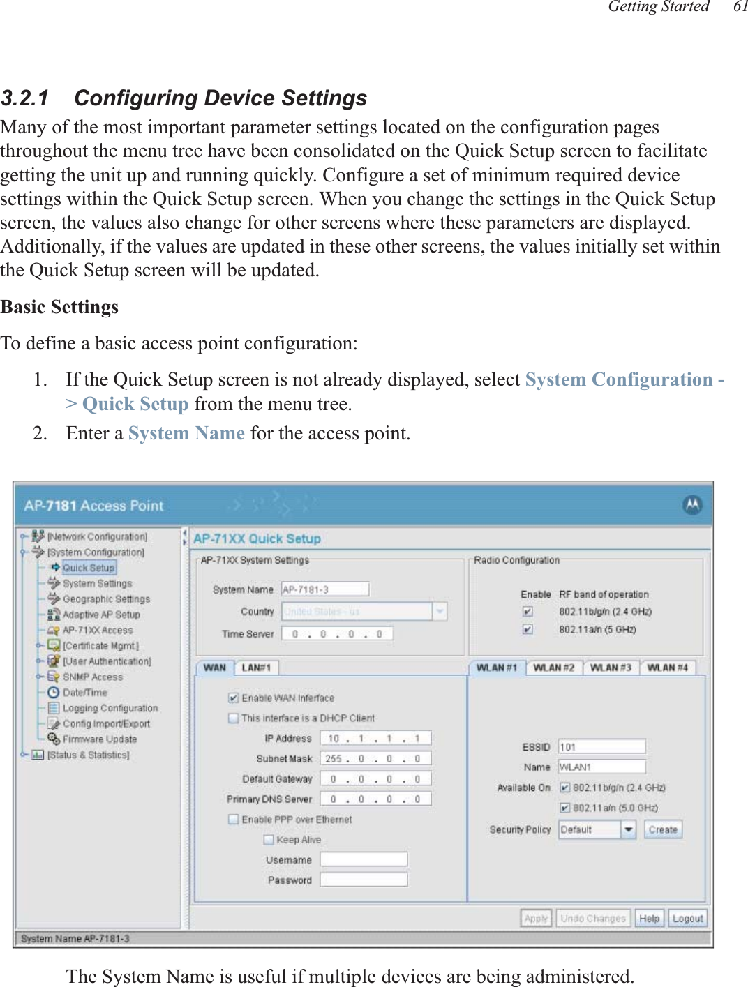
Zebra Technologies Corporation Mesh AP-7181 Outdoor Wireless Access Point 72 70931 01
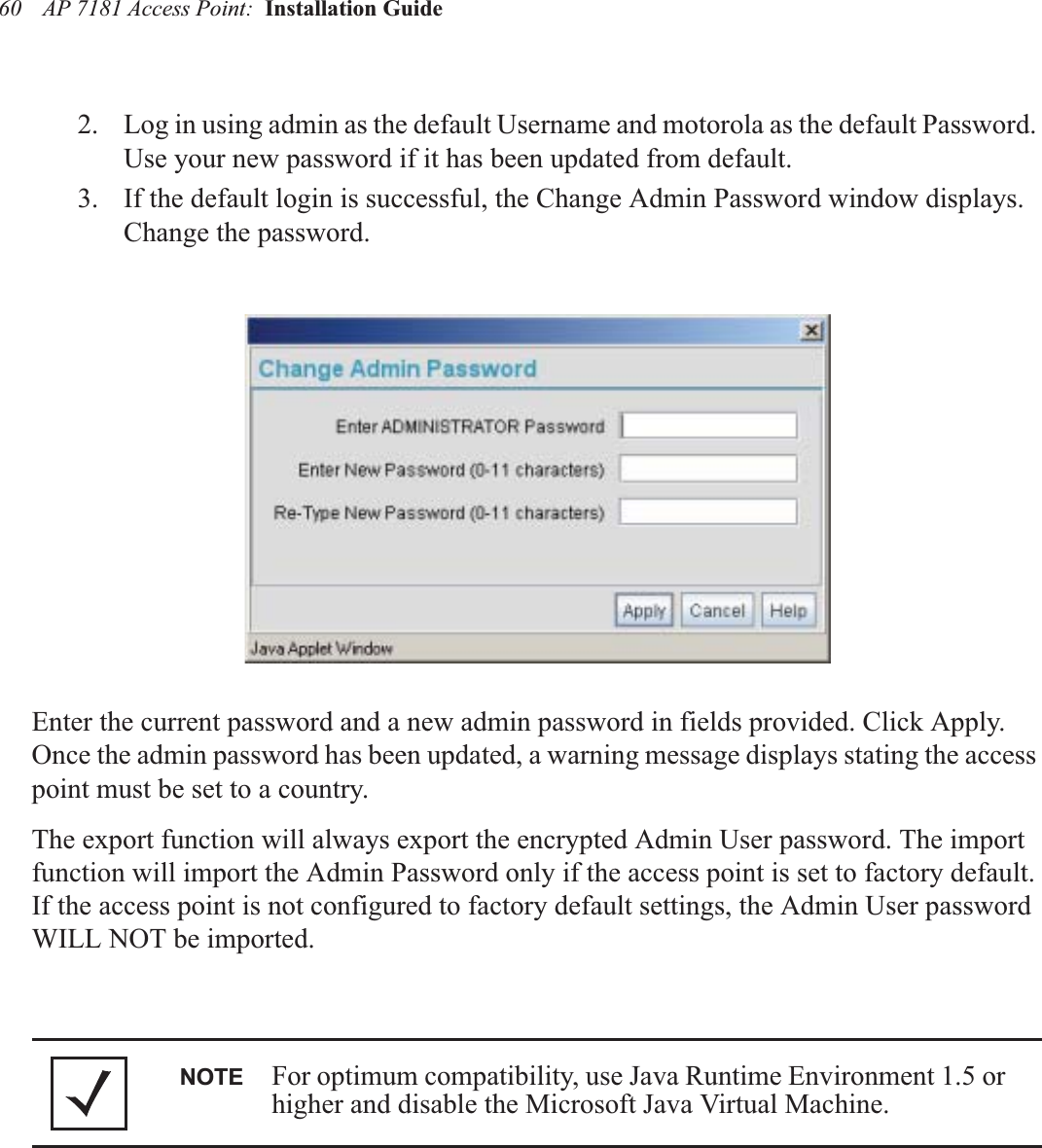
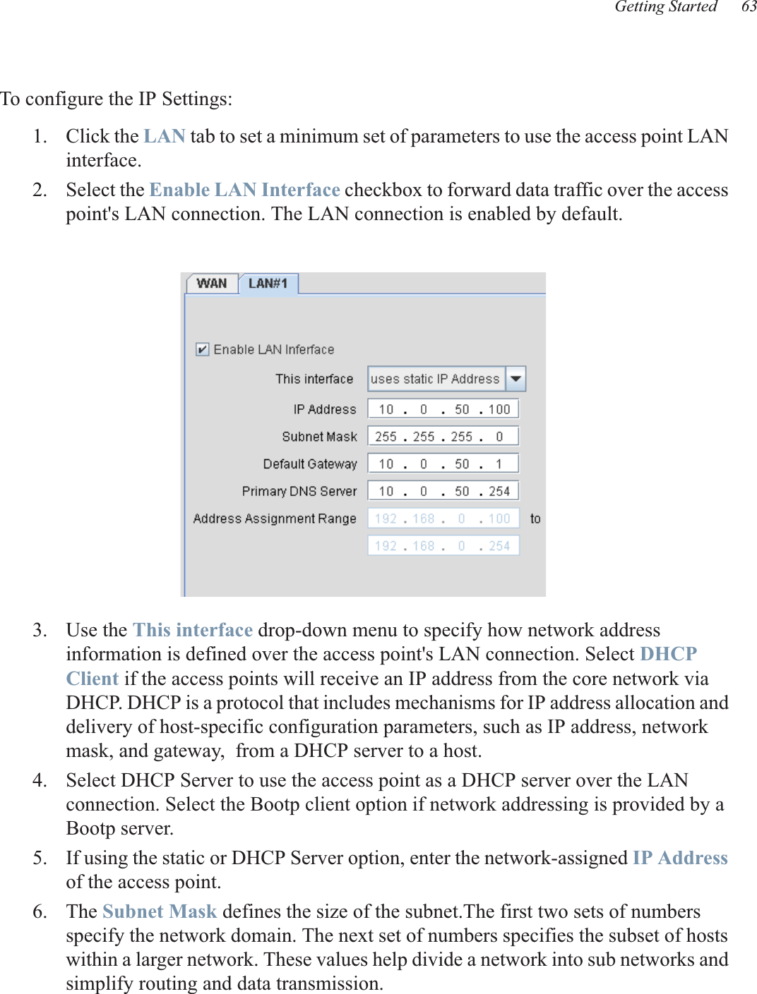
UserManual.wiki
>
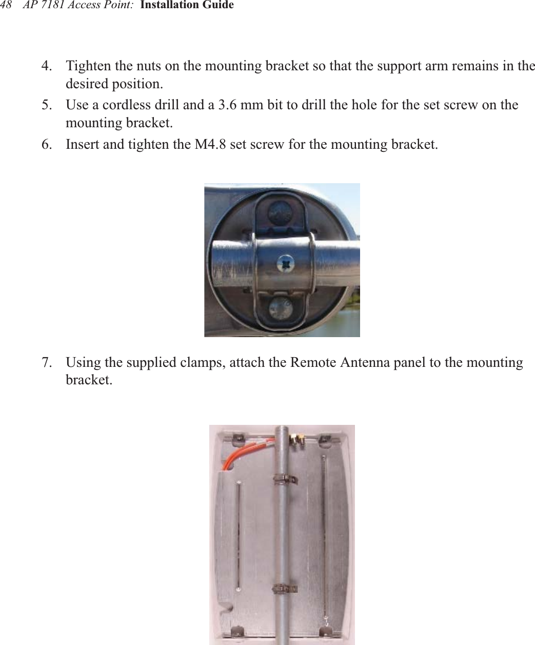
Zebra Technologies
>
MM718101 User Manual
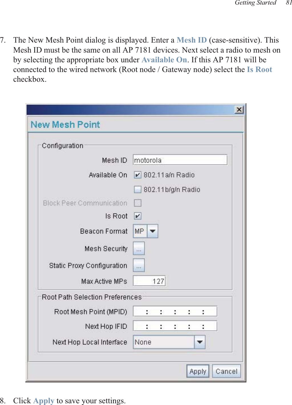
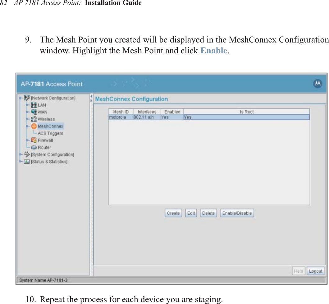
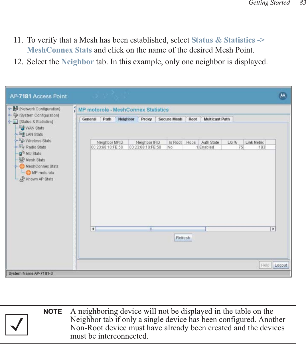
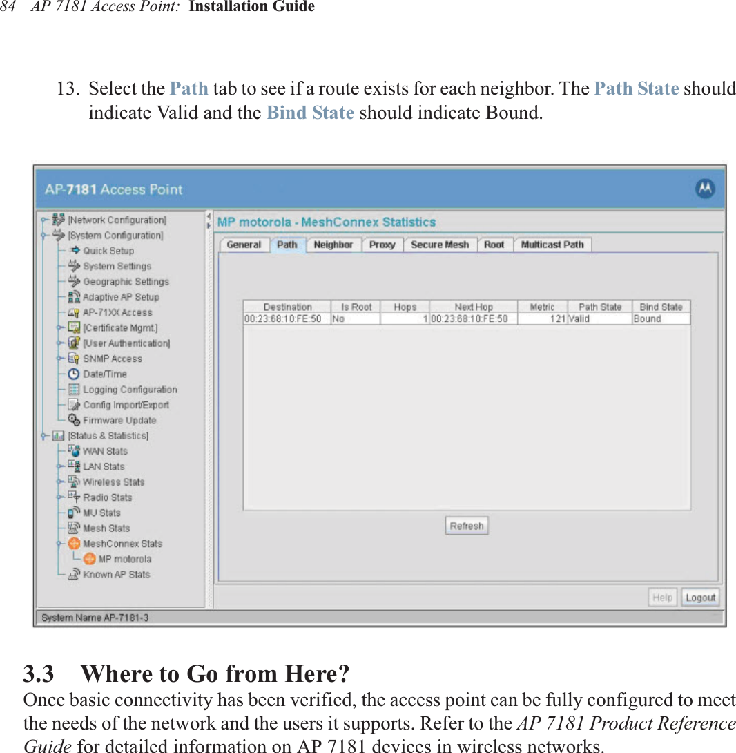
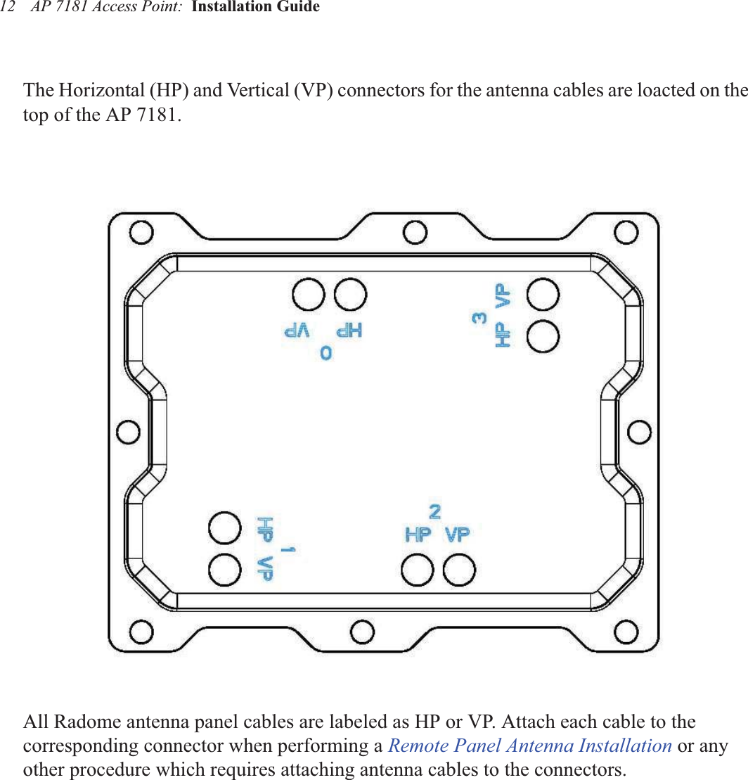
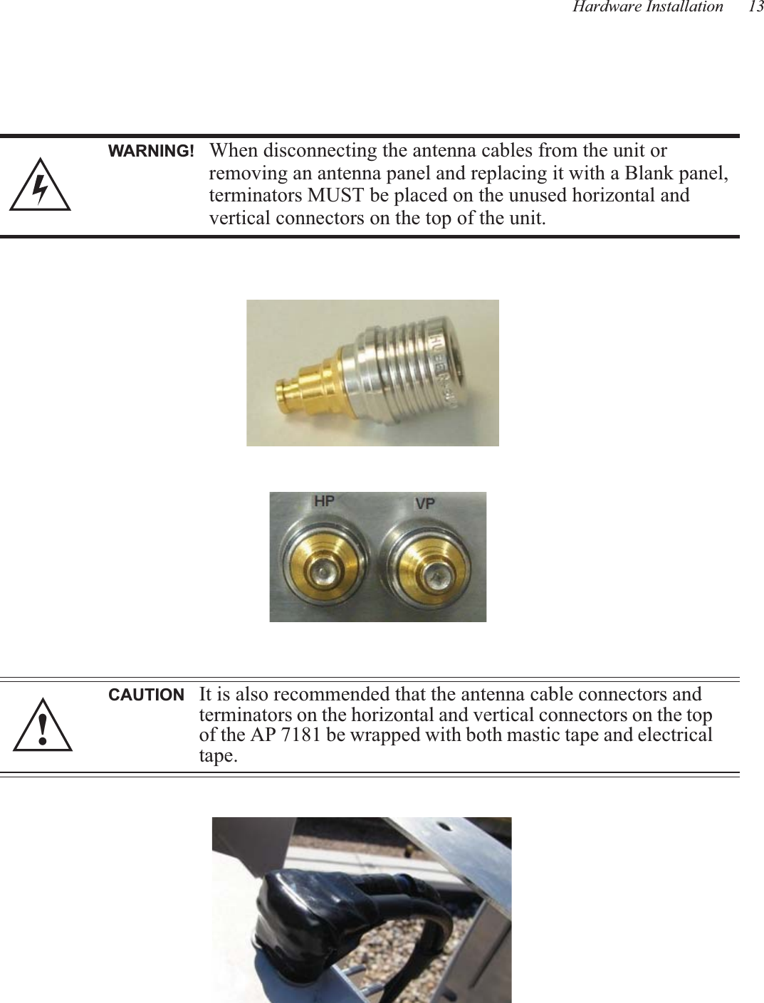
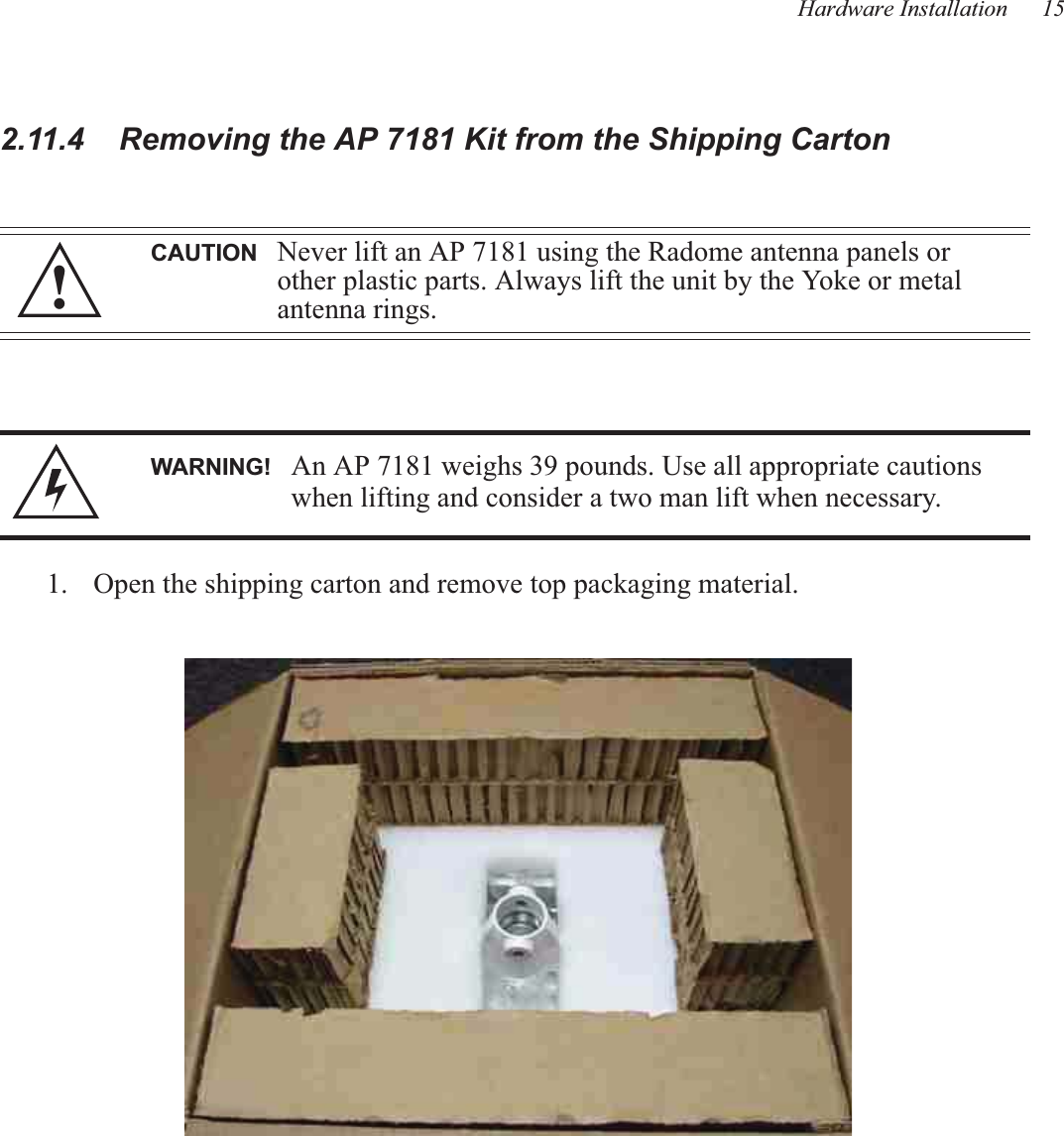
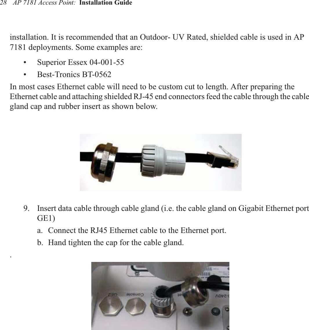
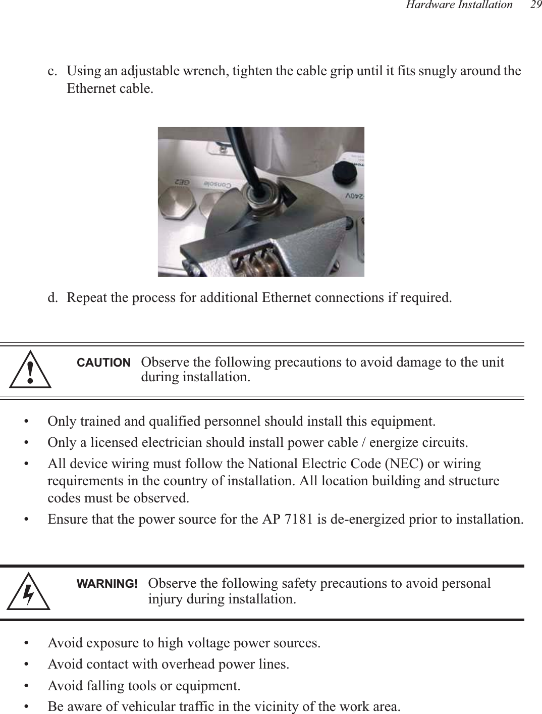
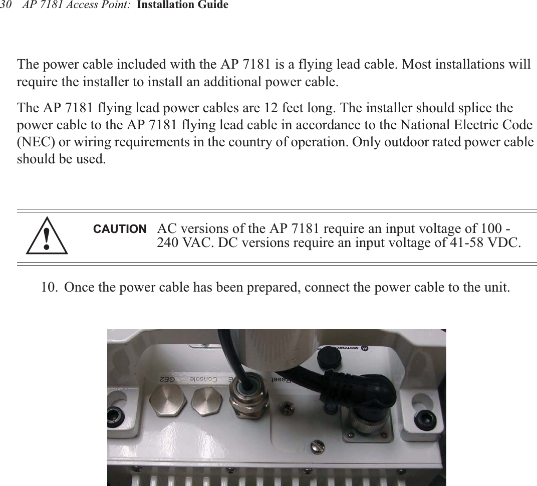
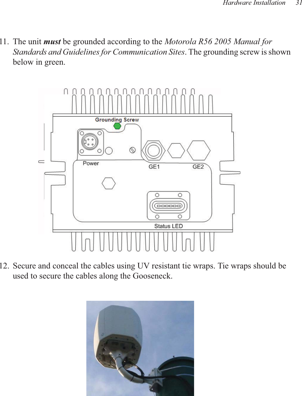
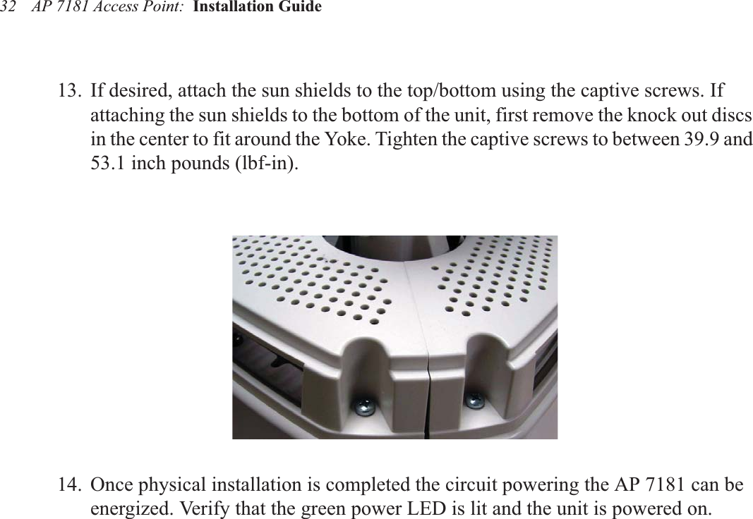
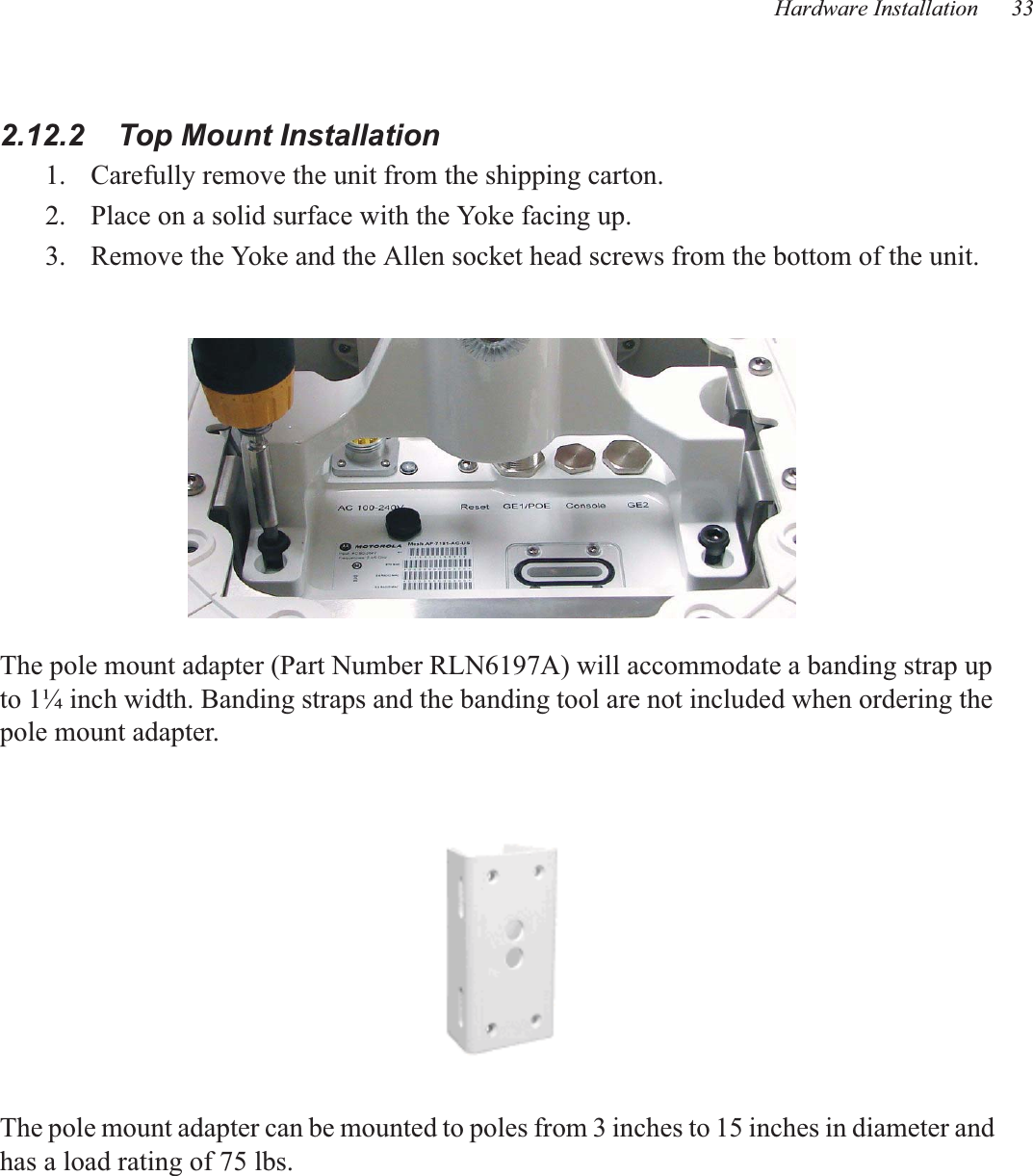
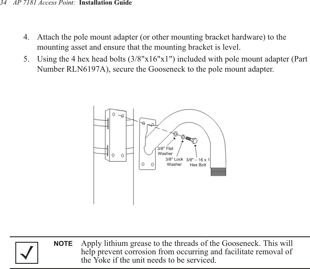
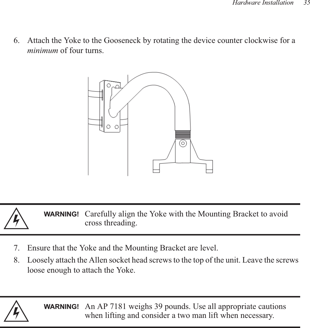
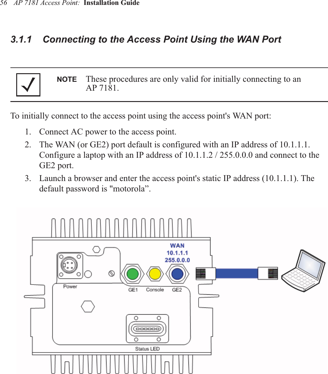
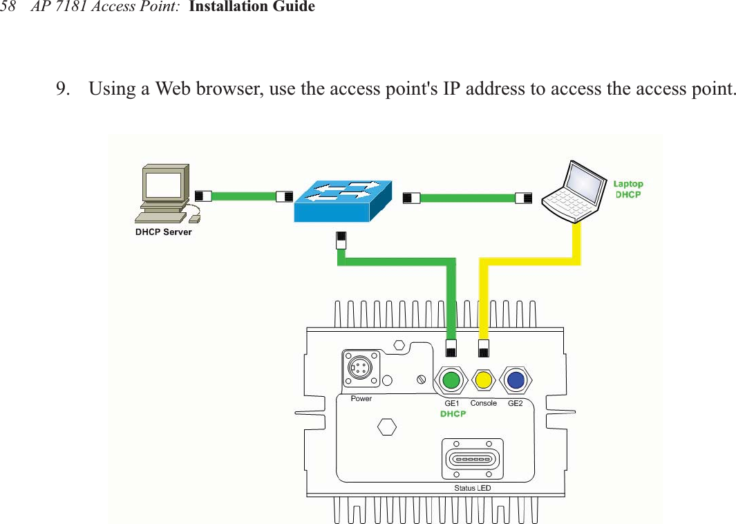
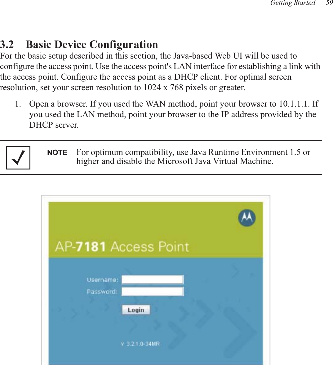
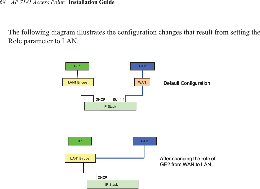
Installation Guide
Navigation menu
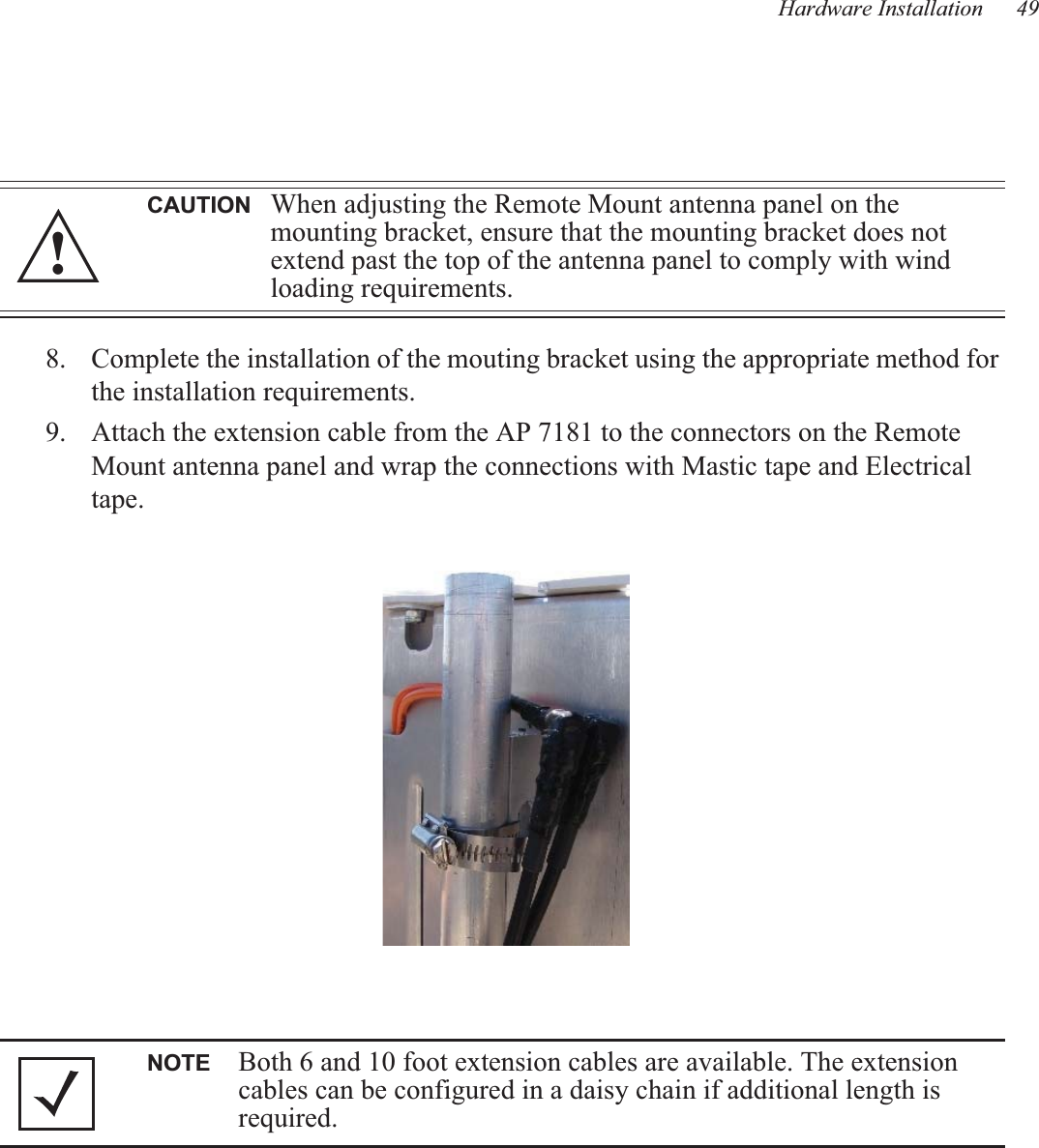
Upload a User Manual
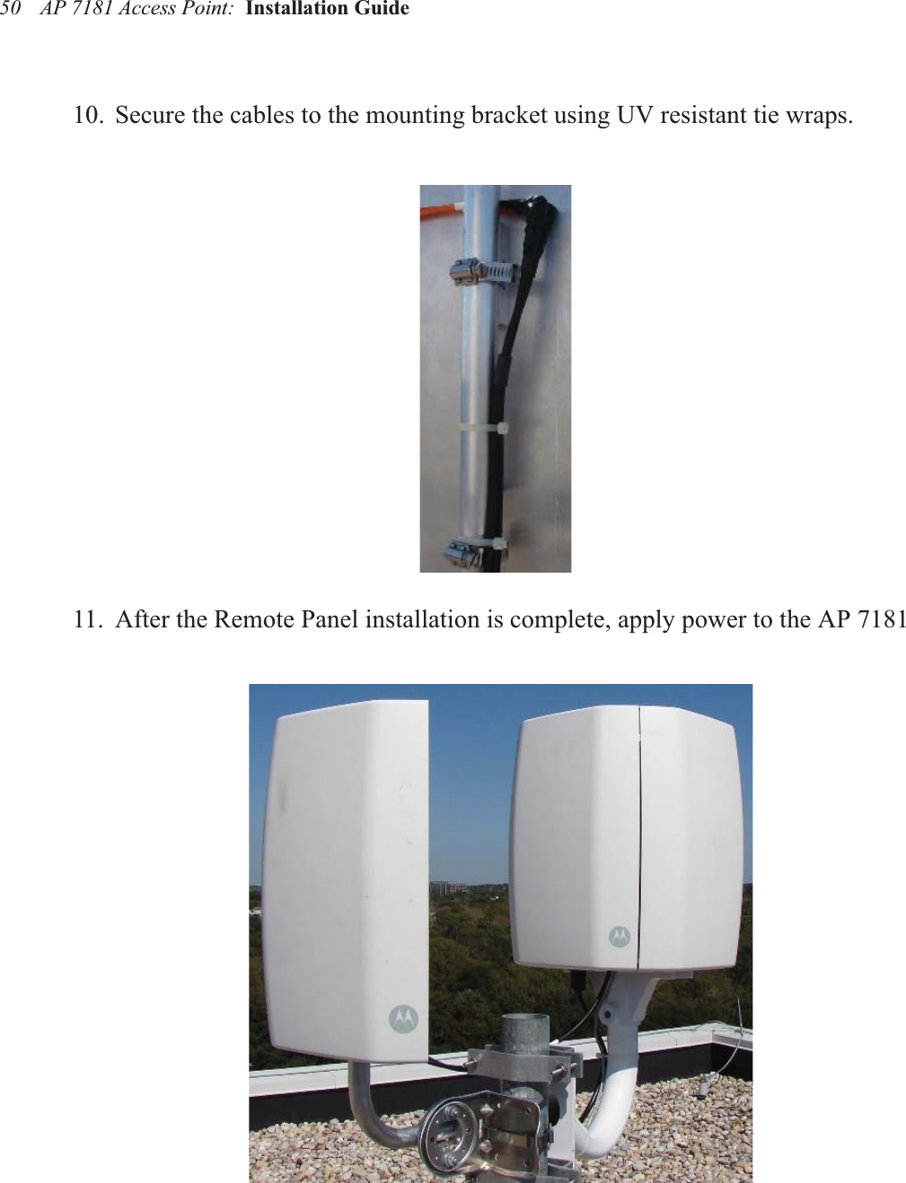
Namespaces
Wiki Guide
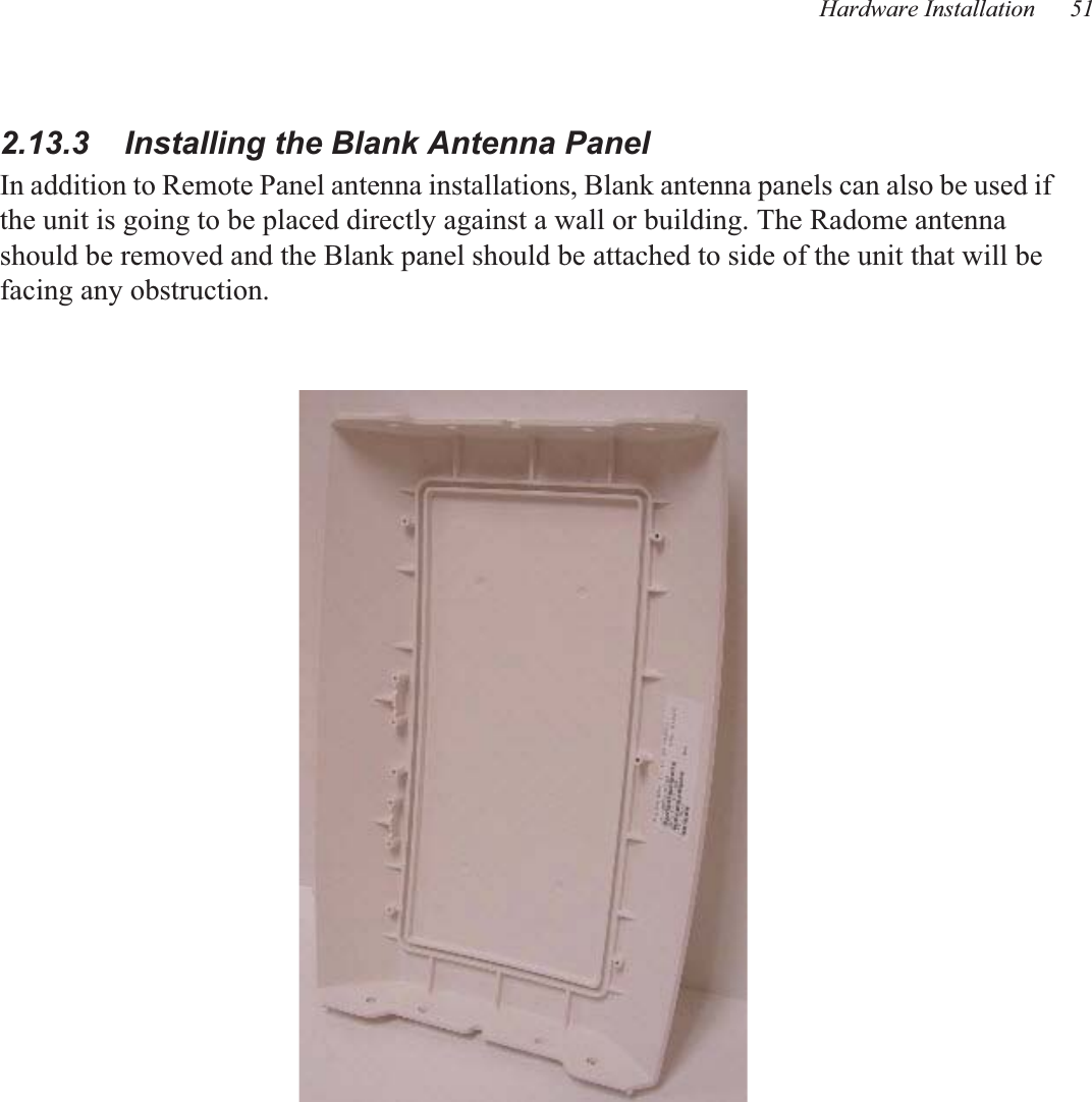
HTML
PDF
Info
Views
User Manual
Discussion / Help
Navigation

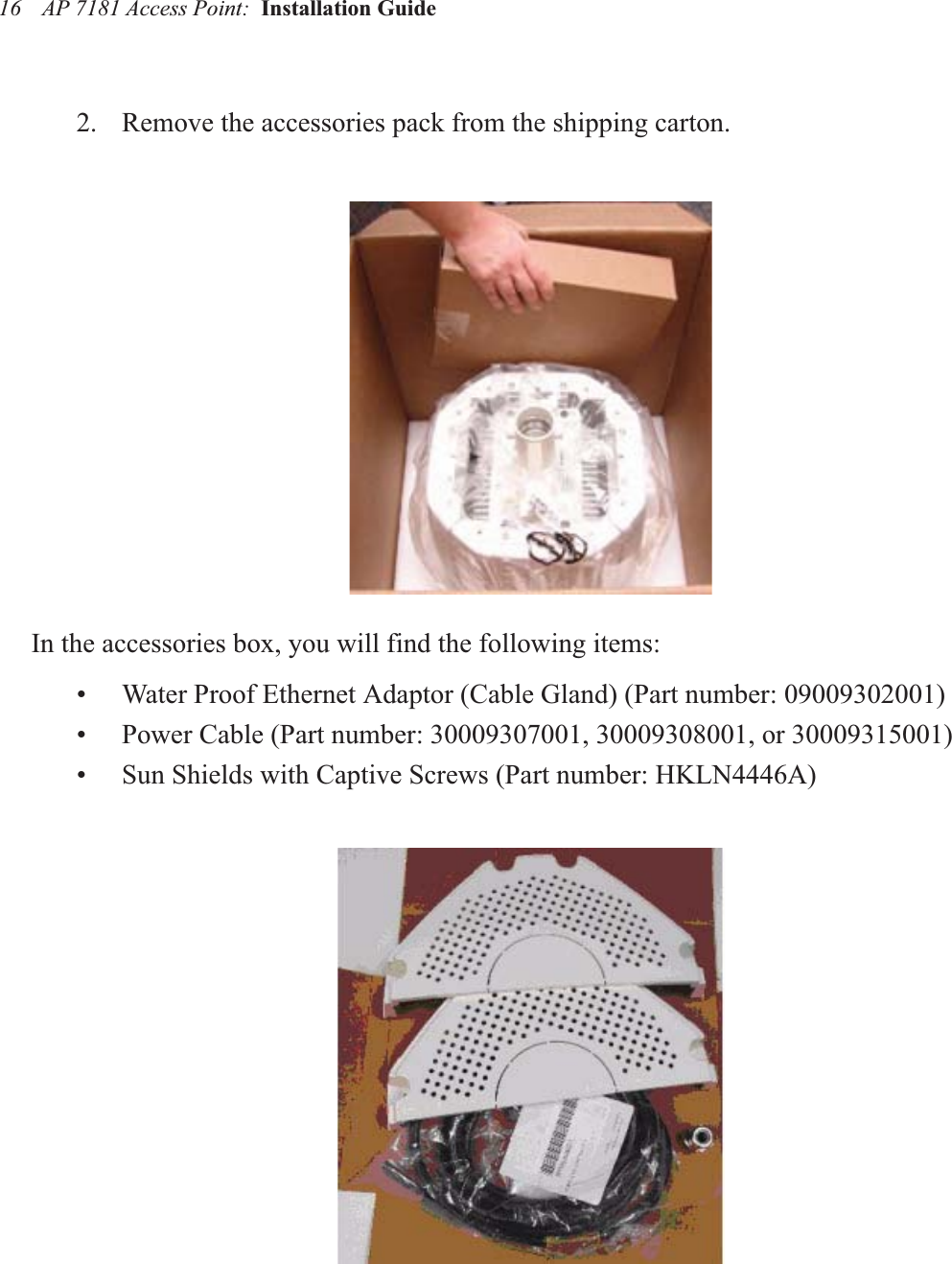
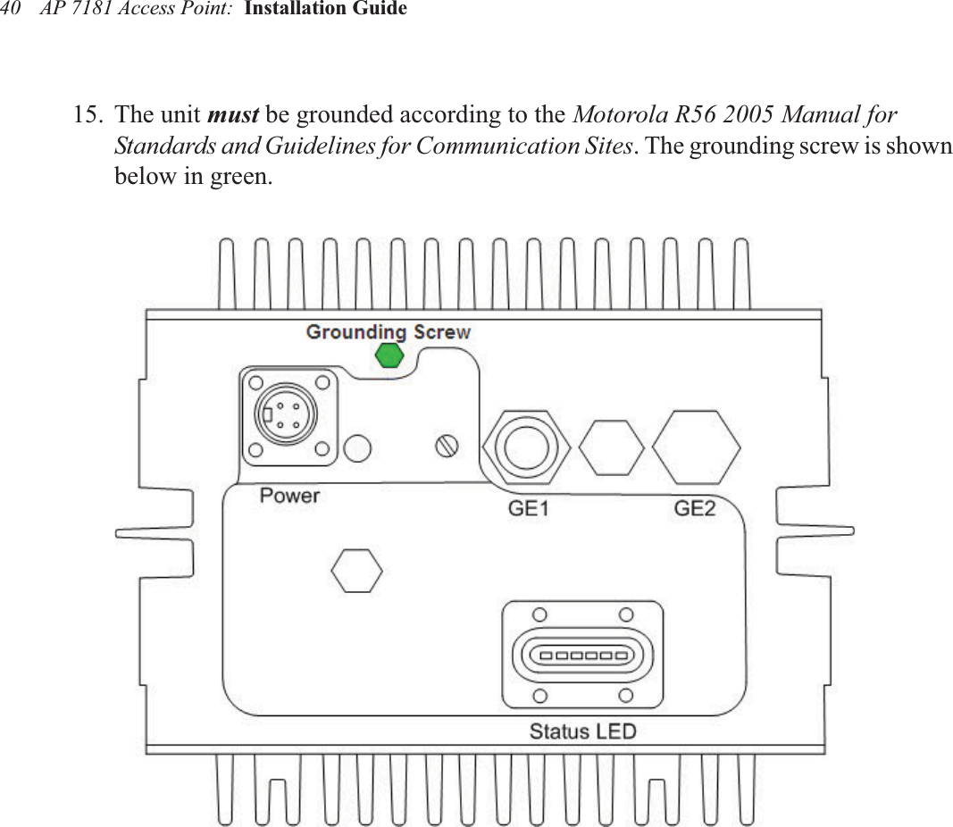
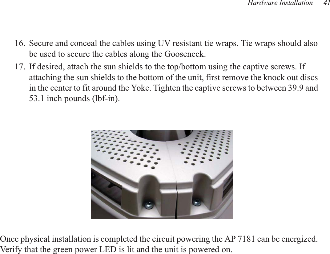
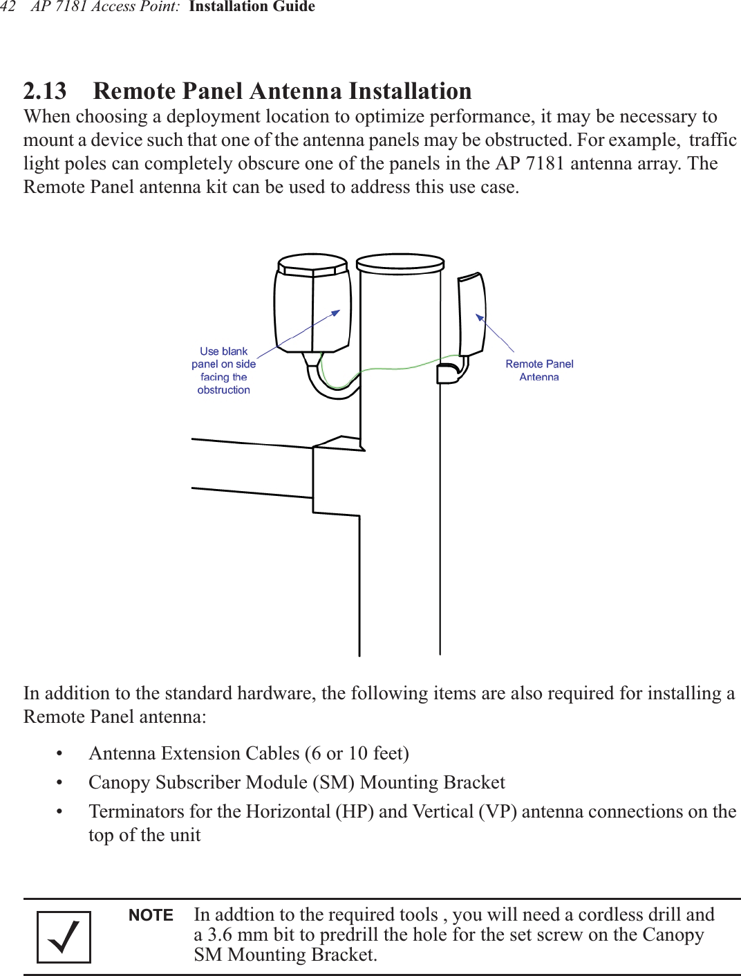
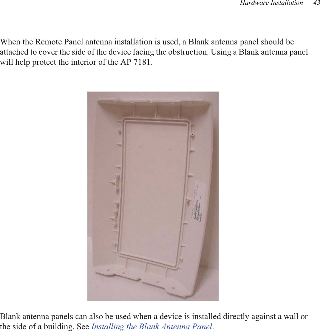
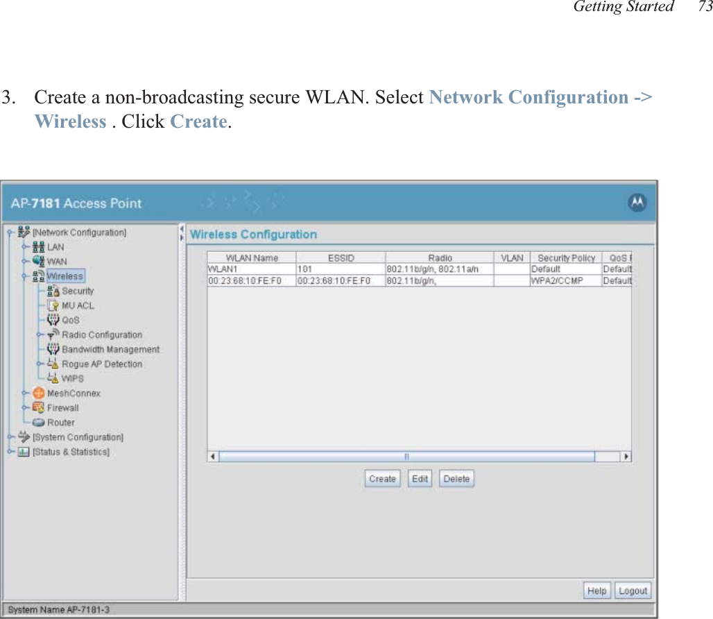
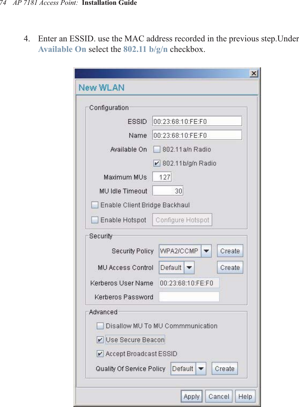
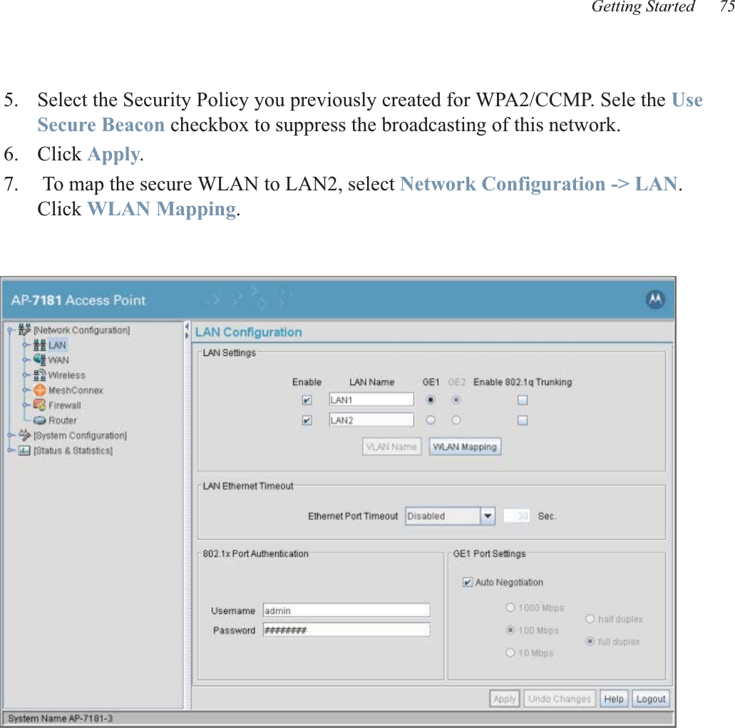
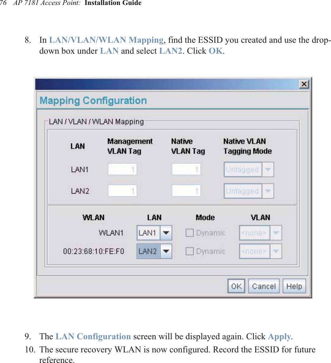
![AP 7181 Access Point: Installation Guide 722. Determine what ESSID (or network name) to use. It is recommended that a unique ESSID be used for each AP 7181. Since the recovery WLAN is going to be on the 2.4 GHz radio, we chose to use the MAC address of the 2.4 GHz radio. This can be found by selecting Radio1 [802.11b/g/n] located under Network Configuration - Wireless - Radio Configuration. The radio MAC address is located in the properties window. Record this MAC address.](https://usermanual.wiki/Zebra-Technologies/MM718101/User-Guide-1259279-Page-78.png)