Zebra Technologies RFID-R110PAX01 Thermal Transfer on Demand Bar Code Printer User Manual R110PAX3 User Guide
Zebra Technologies Corporation Thermal Transfer on Demand Bar Code Printer R110PAX3 User Guide
Contents
- 1. Users Manual Part 1
- 2. Users Manual Part 2
Users Manual Part 1
Zebra® R110PA X 3™
Print Engine
User Guide
Customer Order # 58981L-001
Manufacturer Part # 58981L-001 Rev. 1
© 2004 ZIH Corp.
The copyrights in this manual and the label print engine described therein are
owned by Zebra Technologies. Unauthorized reproduction of this manual or the
software in the label print engine may result in imprisonment of up to one year
and fines of up to $10,000 (17 U.S.C.506). Copyright violators may be subject to
civil liability.
All product names and numbers are Zebra trademarks, and Zebra, the Zebra logo,
ZPL, ZPL II, ZebraNet, ZebraLink, are registered trademarks of ZIH Corp. All
rights reserved.
All other brand names, product names, or trademarks belong to their respective
holders.

58981L-001 Rev. 1 9/7/2004 R110PAX3 User Guide iii
Contents
About This Document . . . . . . . . . . . . . . . . . . . . . . . . . . . . . . . . . . . . . . . . . . . . . . . 1
Who Should Use This Document . . . . . . . . . . . . . . . . . . . . . . . . . . . . . . . . . . . . . . . . . . . . 2
How This Document Is Organized . . . . . . . . . . . . . . . . . . . . . . . . . . . . . . . . . . . . . . . . . . . 2
Contacts . . . . . . . . . . . . . . . . . . . . . . . . . . . . . . . . . . . . . . . . . . . . . . . . . . . . . . . . . . . . . . . 3
Support . . . . . . . . . . . . . . . . . . . . . . . . . . . . . . . . . . . . . . . . . . . . . . . . . . . . . . . . . . . . . 3
Document Conventions. . . . . . . . . . . . . . . . . . . . . . . . . . . . . . . . . . . . . . . . . . . . . . . . . . . . 4
Related Documents . . . . . . . . . . . . . . . . . . . . . . . . . . . . . . . . . . . . . . . . . . . . . . . . . . . . . . 5
1 • Print Engine Basics . . . . . . . . . . . . . . . . . . . . . . . . . . . . . . . . . . . . . . . . . . . . . . 7
Print Engine Exterior View . . . . . . . . . . . . . . . . . . . . . . . . . . . . . . . . . . . . . . . . . . . . . . . . . 8
Front Panel . . . . . . . . . . . . . . . . . . . . . . . . . . . . . . . . . . . . . . . . . . . . . . . . . . . . . . . . . . . . . 9
Front Panel Buttons . . . . . . . . . . . . . . . . . . . . . . . . . . . . . . . . . . . . . . . . . . . . . . . . . . . 9
Front Panel Indicator Lights (LEDs) . . . . . . . . . . . . . . . . . . . . . . . . . . . . . . . . . . . . . . 10
Power On/Off Switch. . . . . . . . . . . . . . . . . . . . . . . . . . . . . . . . . . . . . . . . . . . . . . . . . . . . . .11
2 • Getting Started . . . . . . . . . . . . . . . . . . . . . . . . . . . . . . . . . . . . . . . . . . . . . . . . . 13
Before You Begin . . . . . . . . . . . . . . . . . . . . . . . . . . . . . . . . . . . . . . . . . . . . . . . . . . . . . . . 14
Unpack and Inspect the Print Engine . . . . . . . . . . . . . . . . . . . . . . . . . . . . . . . . . . . . . . . . 15
Report Shipping Damage . . . . . . . . . . . . . . . . . . . . . . . . . . . . . . . . . . . . . . . . . . . . . . 15
Store the Print Engine. . . . . . . . . . . . . . . . . . . . . . . . . . . . . . . . . . . . . . . . . . . . . . . . . 15
Shipping . . . . . . . . . . . . . . . . . . . . . . . . . . . . . . . . . . . . . . . . . . . . . . . . . . . . . . . . . . . 15
Print Engine Installation . . . . . . . . . . . . . . . . . . . . . . . . . . . . . . . . . . . . . . . . . . . . . . . . . . 16
Requirements . . . . . . . . . . . . . . . . . . . . . . . . . . . . . . . . . . . . . . . . . . . . . . . . . . . . . . . 16
Install the Print Engine in an Applicator . . . . . . . . . . . . . . . . . . . . . . . . . . . . . . . . . . . 21
Connect the Print Engine to a Power Source . . . . . . . . . . . . . . . . . . . . . . . . . . . . . . . . . . 22
Power Cord Specifications . . . . . . . . . . . . . . . . . . . . . . . . . . . . . . . . . . . . . . . . . . . . . 23

iv R110PA X 3 User Guide 9/7/2004 58981L-001 Rev. 1
Contents
Select a Communication Interface . . . . . . . . . . . . . . . . . . . . . . . . . . . . . . . . . . . . . . . . . . 24
Standard Connections . . . . . . . . . . . . . . . . . . . . . . . . . . . . . . . . . . . . . . . . . . . . . . . . 24
Optional Print Servers. . . . . . . . . . . . . . . . . . . . . . . . . . . . . . . . . . . . . . . . . . . . . . . . . 25
DB-15 Applicator Interface Connector . . . . . . . . . . . . . . . . . . . . . . . . . . . . . . . . . . . . 25
System Considerations. . . . . . . . . . . . . . . . . . . . . . . . . . . . . . . . . . . . . . . . . . . . . . . . 25
Interface Considerations. . . . . . . . . . . . . . . . . . . . . . . . . . . . . . . . . . . . . . . . . . . . . . . 25
Data Cable Requirements. . . . . . . . . . . . . . . . . . . . . . . . . . . . . . . . . . . . . . . . . . . . . . 26
Types of Media . . . . . . . . . . . . . . . . . . . . . . . . . . . . . . . . . . . . . . . . . . . . . . . . . . . . . . . . . 27
Ribbon. . . . . . . . . . . . . . . . . . . . . . . . . . . . . . . . . . . . . . . . . . . . . . . . . . . . . . . . . . . . . . . . 29
When to Use Ribbon. . . . . . . . . . . . . . . . . . . . . . . . . . . . . . . . . . . . . . . . . . . . . . . . . . 29
Coated Side of Ribbon . . . . . . . . . . . . . . . . . . . . . . . . . . . . . . . . . . . . . . . . . . . . . . . . 29
3 • Print Engine Operation . . . . . . . . . . . . . . . . . . . . . . . . . . . . . . . . . . . . . . . . . . 31
Load Media . . . . . . . . . . . . . . . . . . . . . . . . . . . . . . . . . . . . . . . . . . . . . . . . . . . . . . . . . . . . 32
Load Ribbon . . . . . . . . . . . . . . . . . . . . . . . . . . . . . . . . . . . . . . . . . . . . . . . . . . . . . . . . . . . 38
Remove Used Ribbon. . . . . . . . . . . . . . . . . . . . . . . . . . . . . . . . . . . . . . . . . . . . . . . . . . . . 43
Print a Configuration Label . . . . . . . . . . . . . . . . . . . . . . . . . . . . . . . . . . . . . . . . . . . . . . . . 44
Print a Network Configuration Label . . . . . . . . . . . . . . . . . . . . . . . . . . . . . . . . . . . . . . . . . 45
Calibrate the Print Engine . . . . . . . . . . . . . . . . . . . . . . . . . . . . . . . . . . . . . . . . . . . . . . . . . 46
Adjust Media Sensors . . . . . . . . . . . . . . . . . . . . . . . . . . . . . . . . . . . . . . . . . . . . . . . . . . . . 48
Reflective Media Sensor. . . . . . . . . . . . . . . . . . . . . . . . . . . . . . . . . . . . . . . . . . . . . . . 48
Transmissive Media Sensor . . . . . . . . . . . . . . . . . . . . . . . . . . . . . . . . . . . . . . . . . . . . 48
4 • Print Engine Configuration . . . . . . . . . . . . . . . . . . . . . . . . . . . . . . . . . . . . . . . 51
Overview. . . . . . . . . . . . . . . . . . . . . . . . . . . . . . . . . . . . . . . . . . . . . . . . . . . . . . . . . . . . . . 52
Enter Setup Mode. . . . . . . . . . . . . . . . . . . . . . . . . . . . . . . . . . . . . . . . . . . . . . . . . . . . 52
Exit Setup Mode . . . . . . . . . . . . . . . . . . . . . . . . . . . . . . . . . . . . . . . . . . . . . . . . . . . . . 52
Changing Password-Protected Parameters . . . . . . . . . . . . . . . . . . . . . . . . . . . . . . . . . . . 54
Default Password Value . . . . . . . . . . . . . . . . . . . . . . . . . . . . . . . . . . . . . . . . . . . . . . . 54
Disable the Password Protection Feature . . . . . . . . . . . . . . . . . . . . . . . . . . . . . . . . . 54
Front Panel LCD . . . . . . . . . . . . . . . . . . . . . . . . . . . . . . . . . . . . . . . . . . . . . . . . . . . . . . . . 55
ZebraNet® Print Server LCD Displays . . . . . . . . . . . . . . . . . . . . . . . . . . . . . . . . . . . . 73
5 • RFID Guidelines . . . . . . . . . . . . . . . . . . . . . . . . . . . . . . . . . . . . . . . . . . . . . . . . 75
Overview. . . . . . . . . . . . . . . . . . . . . . . . . . . . . . . . . . . . . . . . . . . . . . . . . . . . . . . . . . . . . . 76
Transponder Placement . . . . . . . . . . . . . . . . . . . . . . . . . . . . . . . . . . . . . . . . . . . . . . . . . . 76
ZPL II Commands for RFID . . . . . . . . . . . . . . . . . . . . . . . . . . . . . . . . . . . . . . . . . . . . . . . 77
^HV Host Verification . . . . . . . . . . . . . . . . . . . . . . . . . . . . . . . . . . . . . . . . . . . . . . . . . . . 78
^RS RFID Setup . . . . . . . . . . . . . . . . . . . . . . . . . . . . . . . . . . . . . . . . . . . . . . . . . . . . . . 79
^RT Read Tag . . . . . . . . . . . . . . . . . . . . . . . . . . . . . . . . . . . . . . . . . . . . . . . . . . . . . . . . 83
^WT Write Tag . . . . . . . . . . . . . . . . . . . . . . . . . . . . . . . . . . . . . . . . . . . . . . . . . . . . . . . . 85
Sample of RFID Programming . . . . . . . . . . . . . . . . . . . . . . . . . . . . . . . . . . . . . . . . . . . . . 87

Contents
58981L-001 Rev. 1 9/7/2004 R110PAX3 User Guide v
6 • Routine Maintenance . . . . . . . . . . . . . . . . . . . . . . . . . . . . . . . . . . . . . . . . . . . 89
Cleaning Schedule . . . . . . . . . . . . . . . . . . . . . . . . . . . . . . . . . . . . . . . . . . . . . . . . . . . . . . 90
Clean Exterior . . . . . . . . . . . . . . . . . . . . . . . . . . . . . . . . . . . . . . . . . . . . . . . . . . . . . . . . . . 90
Clean Interior . . . . . . . . . . . . . . . . . . . . . . . . . . . . . . . . . . . . . . . . . . . . . . . . . . . . . . . . . . 91
Clean the Sensors . . . . . . . . . . . . . . . . . . . . . . . . . . . . . . . . . . . . . . . . . . . . . . . . . . . 91
Clean the Printhead and Platen Roller . . . . . . . . . . . . . . . . . . . . . . . . . . . . . . . . . . . . 93
Toggle Positioning. . . . . . . . . . . . . . . . . . . . . . . . . . . . . . . . . . . . . . . . . . . . . . . . . . . . . . . 95
Printhead Pressure Adjustment . . . . . . . . . . . . . . . . . . . . . . . . . . . . . . . . . . . . . . . . . . . . 96
Power Fuse Replacement. . . . . . . . . . . . . . . . . . . . . . . . . . . . . . . . . . . . . . . . . . . . . . . . . 97
7 • Troubleshooting . . . . . . . . . . . . . . . . . . . . . . . . . . . . . . . . . . . . . . . . . . . . . . . 99
Troubleshooting Checklists . . . . . . . . . . . . . . . . . . . . . . . . . . . . . . . . . . . . . . . . . . . . . . . 100
LCD Error Messages . . . . . . . . . . . . . . . . . . . . . . . . . . . . . . . . . . . . . . . . . . . . . . . . . . . 101
Memory Errors . . . . . . . . . . . . . . . . . . . . . . . . . . . . . . . . . . . . . . . . . . . . . . . . . . . . . . . . 103
Print Quality Problems . . . . . . . . . . . . . . . . . . . . . . . . . . . . . . . . . . . . . . . . . . . . . . . . . . 104
Communications Problems . . . . . . . . . . . . . . . . . . . . . . . . . . . . . . . . . . . . . . . . . . . . . . . 107
Miscellaneous Print Engine Problems . . . . . . . . . . . . . . . . . . . . . . . . . . . . . . . . . . . . . . 108
Print Engine Diagnostics. . . . . . . . . . . . . . . . . . . . . . . . . . . . . . . . . . . . . . . . . . . . . . . . . .110
Power-On Self Test. . . . . . . . . . . . . . . . . . . . . . . . . . . . . . . . . . . . . . . . . . . . . . . . . . .110
Additional Print Engine Self Tests. . . . . . . . . . . . . . . . . . . . . . . . . . . . . . . . . . . . . . . .110
Communications Diagnostics Test . . . . . . . . . . . . . . . . . . . . . . . . . . . . . . . . . . . . . . .116
A • Print Engine Specifications . . . . . . . . . . . . . . . . . . . . . . . . . . . . . . . . . . . . . 117
General Specifications . . . . . . . . . . . . . . . . . . . . . . . . . . . . . . . . . . . . . . . . . . . . . . . . . . .118
Physical . . . . . . . . . . . . . . . . . . . . . . . . . . . . . . . . . . . . . . . . . . . . . . . . . . . . . . . . . . .118
Environmental Conditions. . . . . . . . . . . . . . . . . . . . . . . . . . . . . . . . . . . . . . . . . . . . . .118
Agency Approvals. . . . . . . . . . . . . . . . . . . . . . . . . . . . . . . . . . . . . . . . . . . . . . . . . . . .118
Electrical Specifications . . . . . . . . . . . . . . . . . . . . . . . . . . . . . . . . . . . . . . . . . . . . . . .119
Fuses . . . . . . . . . . . . . . . . . . . . . . . . . . . . . . . . . . . . . . . . . . . . . . . . . . . . . . . . . . . . .119
Communications Specifications . . . . . . . . . . . . . . . . . . . . . . . . . . . . . . . . . . . . . . . . .119
Memory. . . . . . . . . . . . . . . . . . . . . . . . . . . . . . . . . . . . . . . . . . . . . . . . . . . . . . . . . . . .119
Zebra Programming Language (ZPL II) . . . . . . . . . . . . . . . . . . . . . . . . . . . . . . . . . . 120
Bar Codes. . . . . . . . . . . . . . . . . . . . . . . . . . . . . . . . . . . . . . . . . . . . . . . . . . . . . . . . . 120
Printing Specifications. . . . . . . . . . . . . . . . . . . . . . . . . . . . . . . . . . . . . . . . . . . . . . . . . . . 121
Media Specifications . . . . . . . . . . . . . . . . . . . . . . . . . . . . . . . . . . . . . . . . . . . . . . . . . . . . 122
Ribbon Specifications . . . . . . . . . . . . . . . . . . . . . . . . . . . . . . . . . . . . . . . . . . . . . . . . . . . 123

vi R110PAX3 User Guide 9/7/2004 58981L-001 Rev. 1
Contents
B • Data Ports . . . . . . . . . . . . . . . . . . . . . . . . . . . . . . . . . . . . . . . . . . . . . . . . . . . 125
Parallel Port . . . . . . . . . . . . . . . . . . . . . . . . . . . . . . . . . . . . . . . . . . . . . . . . . . . . . . . . . . 126
Serial Port . . . . . . . . . . . . . . . . . . . . . . . . . . . . . . . . . . . . . . . . . . . . . . . . . . . . . . . . . . . . 127
Serial Pin Configuration . . . . . . . . . . . . . . . . . . . . . . . . . . . . . . . . . . . . . . . . . . . . . . 128
RS-232 Interface Connections . . . . . . . . . . . . . . . . . . . . . . . . . . . . . . . . . . . . . . . . . 129
Applicator Interface Connector . . . . . . . . . . . . . . . . . . . . . . . . . . . . . . . . . . . . . . . . . . . . 132
Applicator Interface Connector Pin Configuration. . . . . . . . . . . . . . . . . . . . . . . . . . . 132
Jumper Configurations for +5 V I/O Applicator Interface Board . . . . . . . . . . . . . . . . 134
Proprietary Statement . . . . . . . . . . . . . . . . . . . . . . . . . . . . . . . . . . . . . . . . . . . . . 137
Warranty Information . . . . . . . . . . . . . . . . . . . . . . . . . . . . . . . . . . . . . . . . . . . . . 139
Printer Software and Firmware License Agreement . . . . . . . . . . . . . . . . . . . . 143
Glossary . . . . . . . . . . . . . . . . . . . . . . . . . . . . . . . . . . . . . . . . . . . . . . . . . . . . . . . . 149
Index . . . . . . . . . . . . . . . . . . . . . . . . . . . . . . . . . . . . . . . . . . . . . . . . . . . . . . . . . . . 153

58981L-001 Rev. 1 9/7/2004 R110PAX3 User Guide 1
About This Document
This section provides you with contact information, document structure and organization, and
additional reference documents.
Contents
Who Should Use This Document . . . . . . . . . . . . . . . . . . . . . . . . . . . . . . . . . . . . . . . . . . . . 2
How This Document Is Organized . . . . . . . . . . . . . . . . . . . . . . . . . . . . . . . . . . . . . . . . . . . 2
Contacts. . . . . . . . . . . . . . . . . . . . . . . . . . . . . . . . . . . . . . . . . . . . . . . . . . . . . . . . . . . . . . . 3
Support . . . . . . . . . . . . . . . . . . . . . . . . . . . . . . . . . . . . . . . . . . . . . . . . . . . . . . . . . . . . . 3
Document Conventions . . . . . . . . . . . . . . . . . . . . . . . . . . . . . . . . . . . . . . . . . . . . . . . . . . . 4
Related Documents . . . . . . . . . . . . . . . . . . . . . . . . . . . . . . . . . . . . . . . . . . . . . . . . . . . . . . 5

2R110PAX3 User Guide 9/7/2004 58981L-001 Rev. 1
About This Document
Who Should Use This Document
Who Should Use This Document
This User Guide is intended for use by any person who needs to operate or troubleshoot
problems with the print engine.
How This Document Is Organized
The User Guide is set up as follows:
Section Description
Print Engine Basics on page 7 This chapter provides a high-level overview of the
print engine and its components.
Getting Started on page 13 This chapter provides the tasks that you must
complete and the issues that you must consider
before you load and configure your print engine.
Print Engine Operation on page 31 If you have completed the tasks and resolved
issues in the checklist in Before You Begin
on page 14, use this chapter to load the print
engine, to calibrate the print engine, and to print
configuration labels.
Print Engine Configuration on page 51 This chapter describes the front panel parameters
that are used to configure the print engine for
operation.
RFID Guidelines on page 75 This chapter provides an overview of how RFID
works and the ZPL commands used to create
RFID labels.
Routine Maintenance on page 89 This chapter provides routine cleaning and
maintenance procedures.
Troubleshooting on page 99 This chapter provides you with information about
LCD, print quality, communications, and other
errors that you might need to troubleshoot. If you
need technical assistance, contact your equipment
supplier.
Print Engine Specifications
on page 117
This appendix provides the features of and
specifications for the print engine.
Data Ports on page 125 This appendix describes the standard
communication ports available to connect the print
engine to your computer or network.
Glossary on page 149 The glossary provides a list of common terms.

About This Document
Contacts
58981L-001 Rev. 1 9/7/2004 R110PAX3 User Guide 3
Contacts
You can contact Zebra Technologies at any of the following:
Visit us at: http://www.zebra.com
Our Mailing Addresses:
Zebra Technologies Corporation
333 Corporate Woods Parkway
Vernon Hills, Illinois 60061.3109 U.S.A
Telephone: +1 847.634.6700
Fax: +1 847.913.8766
Zebra Technologies Europe Limited
Zebra House
The Valley Centre, Gordon Road
High Wycombe
Buckinghamshire HP13 6EQ, UK
Telephone: +44 (0)1494 472872
Fax: +44 (0)1494 450103
Support
You can contact Zebra support at:
Web Address: www.zebra.com/SS/service_support.htm
US Phone Number +1 847.913.2259
UK/International Phone Number +44 (0) 1494 768289
Note • The web address is case-sensitive.
4R110PAX3 User Guide 9/7/2004 58981L-001 Rev. 1
About This Document
Document Conventions
Document Conventions
The following conventions are used throughout this document to convey certain information:
Alternate Color (online only) Cross-references contain hot links to other sections in this
guide. If you are viewing this guide online in .pdf format, you can click the cross-reference
(blue text) to jump directly to its location.
Command Line Examples All command line examples appear in Courier New font.
For example, type the following to get to the Post-Install scripts in the bin directory:
Ztools
Files and Directories All file names and directories appear in Courier New font. For
example, the Zebra<version number>.tar file and the /root directory.
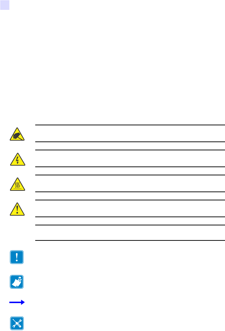
Cautions, Important, Note, and Example
Electrostatic Discharge Caution • Warns you of the potential for electrostatic discharge.
Electric Shock Caution • Warns you of a potential electric shock situation.
Caution • Warns you of a situation where excessive heat could cause a burn.
Caution • Advises you that failure to take or avoid a specific action could result in physical
harm to you.
Caution • Advises you that failure to take or avoid a specific action could result in physical
harm to the hardware.
Important • Advises you of information that is essential to complete a task.
Note • Indicates neutral or positive information that emphasizes or supplements important
points of the main text.
Example • Provides an example, often a scenario, to better clarify a section of text.
Tools • Tells you what tools you need to complete a given task.
About This Document
Related Documents
58981L-001 Rev. 1 9/7/2004 R110PAX3 User Guide 5
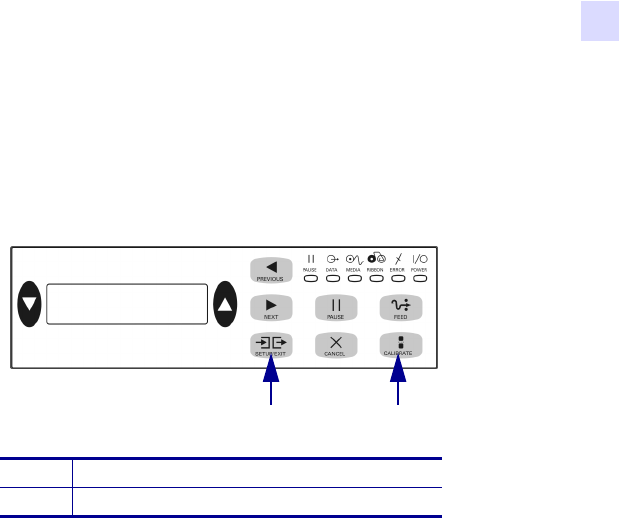
Illustration Callouts Callouts are used when an illustration contains information that needs
to be labeled and described. A table that contains the labels and descriptions follows the
graphic. Figure 1 provides an example.
Figure 1 • Sample Figure with Callouts
Related Documents
The following documents might be helpful references:
•ZPL II® Programming Guide Volume I (part number 45541L) and Vo l u m e I I (part
number 45542L).
• PrintServer II User and Reference Guide (part number 45537L)
1SETUP/EXIT button
2CALIBRATE button
21

6R110PAX3 User Guide 9/7/2004 58981L-001 Rev. 1
About This Document
Related Documents
Notes • ___________________________________________________________________
__________________________________________________________________________
__________________________________________________________________________
__________________________________________________________________________
__________________________________________________________________________
__________________________________________________________________________
__________________________________________________________________________
__________________________________________________________________________
__________________________________________________________________________
__________________________________________________________________________
__________________________________________________________________________
__________________________________________________________________________
__________________________________________________________________________
__________________________________________________________________________
__________________________________________________________________________
__________________________________________________________________________
__________________________________________________________________________
__________________________________________________________________________
__________________________________________________________________________
To provide feedback on this document, please send your comments to techpubs@zebra.com, or
write your comments on this page and fax to the following:
Fax: 1.847.821.1795 Attention: TechPubs — CTC

58981L-001 Rev. 1 9/7/2004 R110PAX3 User Guide 7
1
Print Engine Basics
This chapter provides a high-level overview of the print engine and its components.
Contents
Print Engine Exterior View . . . . . . . . . . . . . . . . . . . . . . . . . . . . . . . . . . . . . . . . . . . . . . . . . 8
Front Panel. . . . . . . . . . . . . . . . . . . . . . . . . . . . . . . . . . . . . . . . . . . . . . . . . . . . . . . . . . . . . 9
Front Panel Buttons . . . . . . . . . . . . . . . . . . . . . . . . . . . . . . . . . . . . . . . . . . . . . . . . . . . . 9
Front Panel Indicator Lights (LEDs). . . . . . . . . . . . . . . . . . . . . . . . . . . . . . . . . . . . . . . 10
Power On/Off Switch . . . . . . . . . . . . . . . . . . . . . . . . . . . . . . . . . . . . . . . . . . . . . . . . . . . . 11
Print Engine Basics
Front Panel
58981L-001 Rev. 1 9/7/2004 R110PAX3 User Guide 9
Front Panel
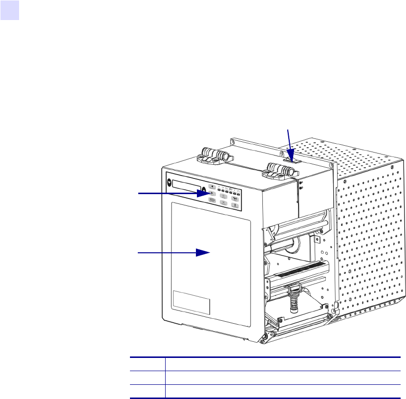
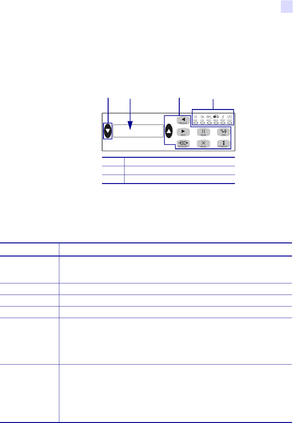
All controls and indicators for the print engine are located on the front of the print engine on
the front panel (Figure 3). The Liquid Crystal Display (LCD) shows operating status and
feature parameters. The front panel buttons are used to control the print engine operations and
to set parameters. The front panel lights (LEDs) indicate the print engine’s status.
Figure 3 • Front Panel
Front Panel Buttons
The front panel buttons are shown in Table 1.
1Buttons
2LCD
3Lights/LEDs
2 1 31
Table 1 • Front Panel Buttons
Button Description/Function
BLACK OVALS The two black ovals are used to change values for the parameter displayed on the LCD.
Common uses include increasing or decreasing a value, answering yes or no, indicating
ON or OFF, and scrolling through choices.
PREVIOUS Scrolls the LCD to the previous parameter.
NEXT Scrolls the LCD to the next parameter.
SETUP/EXIT Enters and exits Setup mode.
PAUSE Stops and restarts the printing process or removes error messages and clears the LCD.
When the print engine is paused, the PAUSE light is on.
• If the print engine is idle, it enters Pause mode immediately.
• If the print engine is printing, the label is completed before the printing process
stops.
CANCEL CANCEL functions only in PAUSE mode. Pressing CANCEL has these effects:
• Cancels the label format that is currently printing.
• If no label format is printing, the next one to be printed is canceled.
• If no label formats are waiting to be printed, CANCEL is ignored.
To clear the print engine’s entire label format memory, press and hold CANCEL until
the DATA light turns off.

10 R110PA X 3 User Guide 9/7/2004 58981L-001 Rev. 1
Print Engine Basics
Front Panel
Front Panel Indicator Lights (LEDs)
The front panel lights are described in Table 2.
FEED Feeds a blank label.
• If the print engine is idle or paused, the label is fed immediately.
• If the print engine is printing, the label is fed after the current batch finishes printing.
CALIBRATE CALIBRATE functions only in PAUSE mode. Press CALIBRATE to recalibrate for
proper media length, to set media type (continuous/non-continuous), and to set print
method (direct thermal/thermal transfer).
Table 1 • Front Panel Buttons (Continued)
Button Description/Function
Table 2 • Front Panel Lights
LED OFF Indicates ON Indicates FLASHING Indicates
POWER
(Green)
Print engine is
OFF, or no power
to print engine.
Power switch is ON, and power is
being supplied to print engine.
—
PAUSE
(Yellow)
Normal operation. One of the following:
• Print engine is paused because of
an error condition (printhead,
ribbon, or paper error). Usually
occurs in conjunction with another
LED.
• PAUSE was pressed.
• A pause was requested from the
Applicator Port.
• A pause was received as part of
the label format.
—
DATA
(Green)
No data being
received or
processed.
Data is processing or printing is
taking place. No data is being
received.
Print engine is receiving data from
or sending status information to
the host computer.
MEDIA
(Yellow)
Normal operation.
Media properly
loaded.
Out of media. (Print engine is
paused, LCD displays error message,
and PAUSE light is ON).
—
RIBBON
(Yellow)
Normal operation.
Ribbon properly
loaded.
Ribbon in while print engine is in
direct thermal mode, or no ribbon
loaded while print engine is in
thermal transfer mode. Print engine
is paused, LCD displays error
message, and PAUSE light is ON.
—
ERROR
(Orange)
No print engine
errors.
— Print engine error exists. Check
the LCD for status.
Print Engine Basics
Power On/Off Switch
58981L-001 Rev. 1 9/7/2004 R110PAX3 User Guide 11
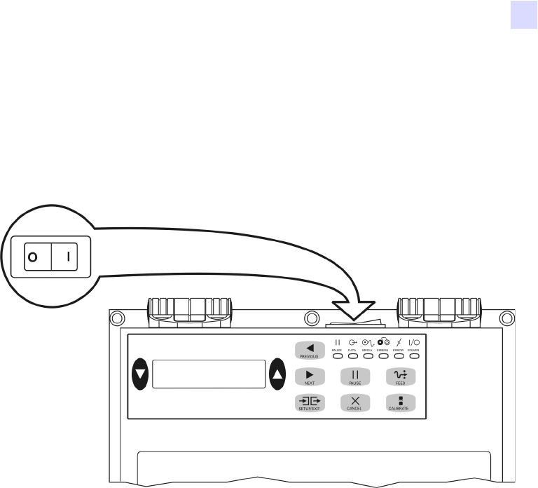
Power On/Off Switch
The power on/off switch is located on the top of the print engine housing, as shown in
Figure 4. When this switch is placed in the ON (I) position, the POWER light turns on, and the
print engine automatically performs a Power-On Self Test (POST). For more information, see
Power-On Self Test on page 110.
Figure 4 • Print Engine Power Switch

12 R110PA X 3 User Guide 9/7/2004 58981L-001 Rev. 1
Print Engine Basics
Power On/Off Switch
Notes • ___________________________________________________________________
__________________________________________________________________________
__________________________________________________________________________
__________________________________________________________________________
__________________________________________________________________________
__________________________________________________________________________
__________________________________________________________________________
__________________________________________________________________________
__________________________________________________________________________
__________________________________________________________________________

58981L-001 Rev. 1 9/7/2004 R110PAX3 User Guide 13
2
Getting Started
This chapter provides the tasks that you must complete and the issues that you must consider
before you load and configure your print engine.
Contents
Before You Begin . . . . . . . . . . . . . . . . . . . . . . . . . . . . . . . . . . . . . . . . . . . . . . . . . . . . . . . 14
Unpack and Inspect the Print Engine. . . . . . . . . . . . . . . . . . . . . . . . . . . . . . . . . . . . . . . . 15
Report Shipping Damage. . . . . . . . . . . . . . . . . . . . . . . . . . . . . . . . . . . . . . . . . . . . . . . 15
Store the Print Engine . . . . . . . . . . . . . . . . . . . . . . . . . . . . . . . . . . . . . . . . . . . . . . . . . 15
Shipping . . . . . . . . . . . . . . . . . . . . . . . . . . . . . . . . . . . . . . . . . . . . . . . . . . . . . . . . . . . . 15
Print Engine Installation . . . . . . . . . . . . . . . . . . . . . . . . . . . . . . . . . . . . . . . . . . . . . . . . . . 16
Requirements. . . . . . . . . . . . . . . . . . . . . . . . . . . . . . . . . . . . . . . . . . . . . . . . . . . . . . . . 16
Install the Print Engine in an Applicator . . . . . . . . . . . . . . . . . . . . . . . . . . . . . . . . . . . . 21
Connect the Print Engine to a Power Source. . . . . . . . . . . . . . . . . . . . . . . . . . . . . . . . . . 22
Power Cord Specifications . . . . . . . . . . . . . . . . . . . . . . . . . . . . . . . . . . . . . . . . . . . . . . 23
Select a Communication Interface . . . . . . . . . . . . . . . . . . . . . . . . . . . . . . . . . . . . . . . . . . 24
Standard Connections . . . . . . . . . . . . . . . . . . . . . . . . . . . . . . . . . . . . . . . . . . . . . . . . . 24
Optional Print Servers . . . . . . . . . . . . . . . . . . . . . . . . . . . . . . . . . . . . . . . . . . . . . . . . . 25
DB-15 Applicator Interface Connector . . . . . . . . . . . . . . . . . . . . . . . . . . . . . . . . . . . . . 25
System Considerations . . . . . . . . . . . . . . . . . . . . . . . . . . . . . . . . . . . . . . . . . . . . . . . . 25
Interface Considerations . . . . . . . . . . . . . . . . . . . . . . . . . . . . . . . . . . . . . . . . . . . . . . . 25
Data Cable Requirements . . . . . . . . . . . . . . . . . . . . . . . . . . . . . . . . . . . . . . . . . . . . . . 26
Types of Media. . . . . . . . . . . . . . . . . . . . . . . . . . . . . . . . . . . . . . . . . . . . . . . . . . . . . . . . . 27
Ribbon . . . . . . . . . . . . . . . . . . . . . . . . . . . . . . . . . . . . . . . . . . . . . . . . . . . . . . . . . . . . . . . 29
When to Use Ribbon . . . . . . . . . . . . . . . . . . . . . . . . . . . . . . . . . . . . . . . . . . . . . . . . . . 29
Coated Side of Ribbon. . . . . . . . . . . . . . . . . . . . . . . . . . . . . . . . . . . . . . . . . . . . . . . . . 29

14 R110PA X 3 User Guide 9/7/2004 58981L-001 Rev. 1
Getting Started
Before You Begin
Before You Begin
Review this checklist, and resolve any issues before you begin setting up your print engine.
When you are ready, continue with Print Engine Operation on page 31.
Unpack and Inspect the Print Engine Have you unpacked the print engine and
inspected it for damage? If you have not, see Unpack and Inspect the Print Engine
on page 15.
Install the Print Engine Have you considered what factors will affect how the print
engine is installed into an applicator? Is the print engine mounted in an applicator? For
information, see Print Engine Installation on page 16.
Attach a Power Cord Do you have the correct power cord for your print engine? If
you are unsure, see Power Cord Specifications on page 23. To attach the power cord and
connect the print engine to a power source, see Connect the Print Engine to a Power
Source on page 22.
Connect to a Data Source Have you determined how the print engine will connect to
a data source (usually a computer)? For more information, see Select a Communication
Interface on page 24.
Select Media Do you have the correct media for your application? If you are unsure,
see Types of Media on page 27.
Select Ribbon Do you need to use ribbon, and is the appropriate ribbon available, if
needed? If you are unsure, see Ribbon on page 29.

Getting Started
Unpack and Inspect the Print Engine
58981L-001 Rev. 1 9/7/2004 R110PAX3 User Guide 15
Unpack and Inspect the Print Engine
When you unpack the print engine, save all packing materials. Inspect the print engine for
possible damage incurred during shipment. Check all exterior surfaces for damage. Raise the
media door, and inspect the media compartment for damage to components.
Report Shipping Damage
If you discover shipping damage upon inspection:
• Immediately notify the shipping company of the damage, and file a damage report with
them. Zebra is not responsible for any damage incurred during shipment of the equipment
and does not repair this damage under warranty.
• Keep all packaging material for shipping company inspection.
• Notify your authorized Zebra reseller.
Store the Print Engine
If you are not placing the print engine into immediate operation, repackage it using the original
packing materials. You may store the print engine under the following conditions:
• Temperature: –40° to 160°F (–40° to 71°C)
• Relative humidity: 5% to 95% non-condensing
Shipping
If you must ship the print engine, remove any ribbon from the spindles to avoid damaging the
print engine. Carefully pack the print engine into the original container or a suitable alternate
container to avoid damage during transit. A shipping container can be purchased from Zebra if
the original packaging has been lost or destroyed.

16 R110PA X 3 User Guide 9/7/2004 58981L-001 Rev. 1
Getting Started
Print Engine Installation
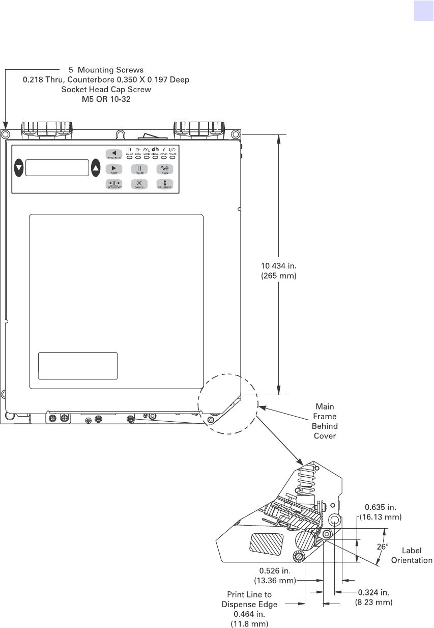
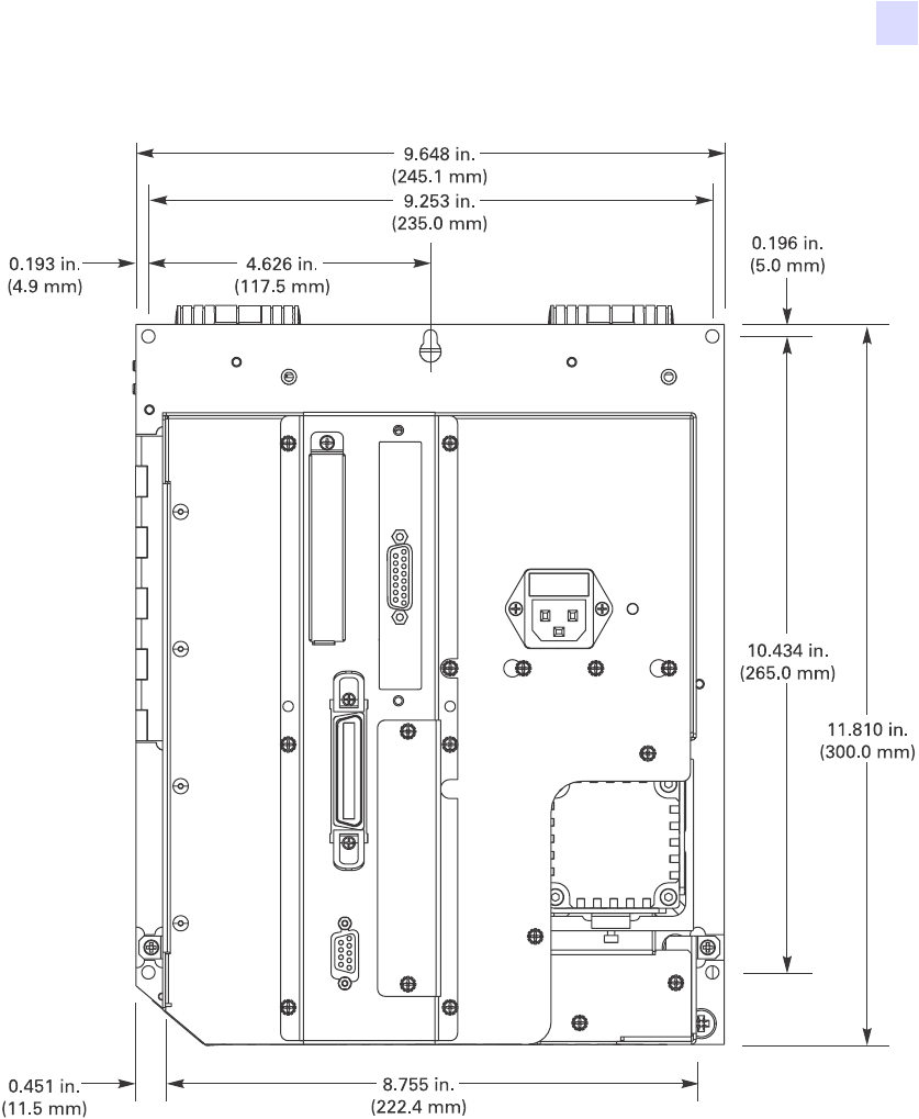
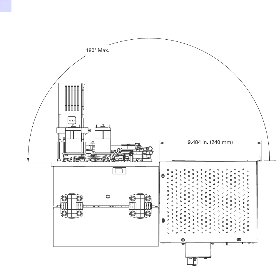
Print Engine Installation
This section provides basic information for mounting the print engine into an applicator. The
illustrations in this section show the print engine from different angles and include
measurements and clearance needs.
Requirements
Stability When the print engine is mounted, the complete assembly must be physically
stable. When the print engine is loaded with ribbon and media, the equipment must not
become physically unstable.
Ventilation and Temperature Provide ventilation for the print engine mounting enclosure
to remove heat and ensure uninterrupted, trouble-free operation of the print engine. Ambient
air temperature surrounding the print engine must not exceed the following:
• Temperature: 32° to 105°F (0° to 41°C)
• Relative humidity: 20% to 95% non-condensing
Power Requirements Consider the current rating of the print engine during installation.
When power is applied to the print engine and the enclosing equipment, an overload condition
must not be created.
Grounding Requirements Maintain reliable grounding of the print engine. Pay particular
attention to the AC power supply connections so that earth ground is maintained through the
AC power input connector.
Clearance for Cables and Connectors Allow ample space at the rear of the print engine
for electronic connectors and dressing of the following cables: IEC power cord, serial and/or
parallel host communication cable, and the discrete signal (applicator) interface cable.
Power Cord Requirements The IEC power cord does not have a strain relief on the print
engine. If the operating characteristics of the applicator include vibration or strain on the
power cord, provide an appropriate clamping mechanism to avoid unintentional disconnection
of the power cord from the print engine.
Getting Started
Print Engine Installation
58981L-001 Rev. 1 9/7/2004 R110PAX3 User Guide 17
Figure 5 • Front View
18 R110PA X 3 User Guide 9/7/2004 58981L-001 Rev. 1
Getting Started
Print Engine Installation
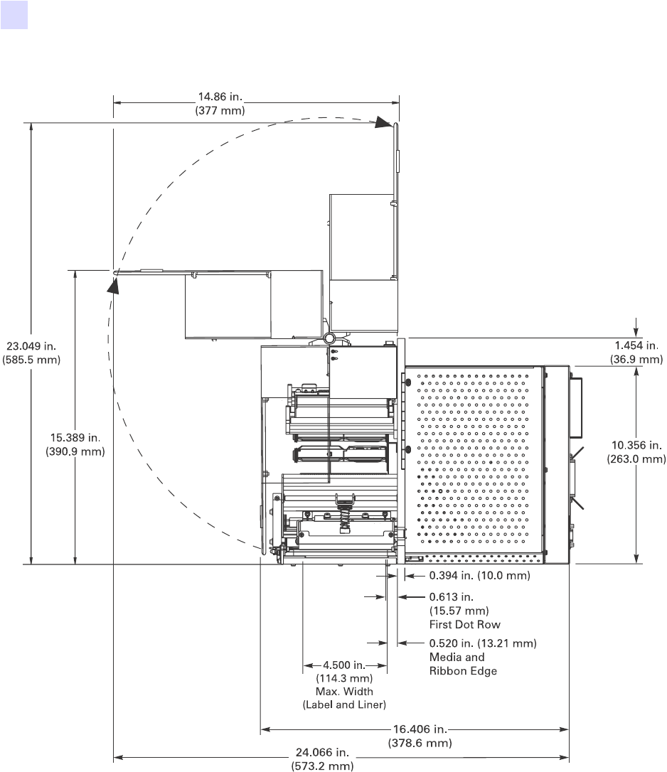
Figure 6 • Right Side View
Getting Started
Print Engine Installation
58981L-001 Rev. 1 9/7/2004 R110PAX3 User Guide 19
Figure 7 • Rear View
20 R110PA X 3 User Guide 9/7/2004 58981L-001 Rev. 1
Getting Started
Print Engine Installation
Figure 8 • Top View
Getting Started
Print Engine Installation
58981L-001 Rev. 1 9/7/2004 R110PAX3 User Guide 21
Install the Print Engine in an Applicator
This section provides the basic instructions for installing the print engine into an applicator.
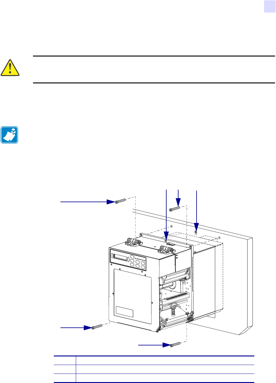
To install the print engine into an applicator, complete these steps:
1. See Figure 9. Install the center mounting bolt into the center hole on the applicator.
2. Carefully place the keyhole on the center mounting bolt.
3. Install the four corner mounting screws to secure the print engine to the applicator.
Figure 9 • Front View of Print Engine in Applicator
Caution • If the print engine is installed improperly, it could fall out of the applicator and
cause injury. The center mounting bolt and four mounting screws must be installed and
secured. See Figure 9 for the location of the bolt and screws.
Note • The keyhole and the center mounting bolt are designed to support the print engine
and assist in installing and removing the four mounting screws.
1Mounting screws (four total)
2Keyhole
3Center mounting bolt (shown inside hole on applicator)
2
1
1
1
3
1
22 R110PA X 3 User Guide 9/7/2004 58981L-001 Rev. 1
Getting Started
Connect the Print Engine to a Power Source
Connect the Print Engine to a Power Source
The power supply in the print engine automatically detects the applied line voltage and works
in the 90 to 264 VAC, 48 to 62 Hz range.
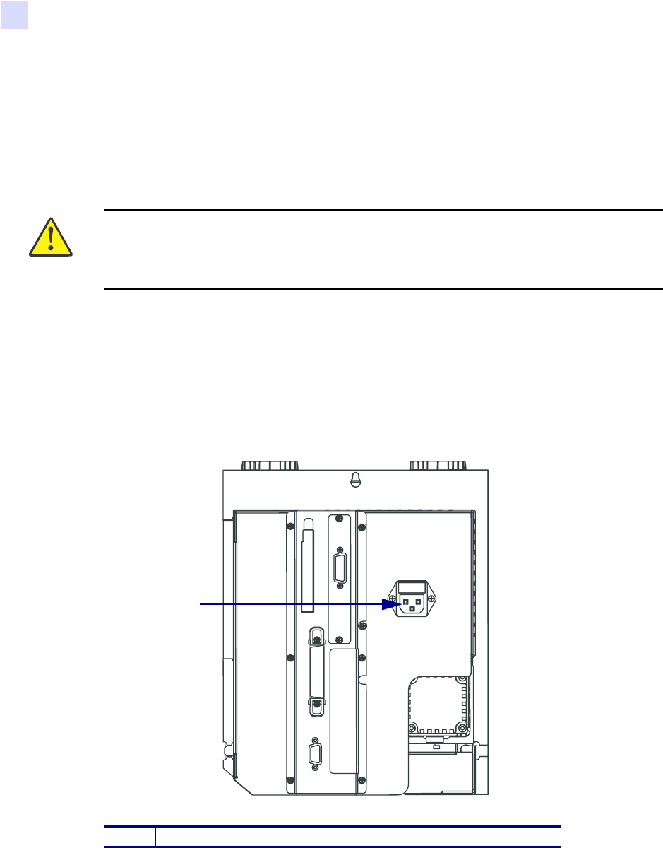
Refer to Figure 10. The AC power cord must have a three-prong female connector on one end
that plugs into the mating AC power connector at the rear of the print engine. If a power cable
was not included with your print engine, refer to Power Cord Specifications on page 23.
To connect the print engine to a power source, complete these steps:
1. Turn Off (O) the print engine power switch (located on the top of the print engine
housing).
2. Plug the power cord into the AC power connector on the rear of the print engine.
Figure 10 • Power Connection
3. Plug the other end of the power cord into the power source.
Caution • For personnel and equipment safety, always use an approved three-conductor
power cord specific to the region or country intended for installation. This cord must use
an IEC 320 female connector and the appropriate region-specific three-conductor
grounded plug configuration.
1AC power connector
1
Getting Started
Connect the Print Engine to a Power Source
58981L-001 Rev. 1 9/7/2004 R110PAX3 User Guide 23
Power Cord Specifications
Depending on how your print engine was ordered, a power cord may or may not be included.
If one is not included or if the one included is not suitable for your requirements, refer to the
following guidelines:
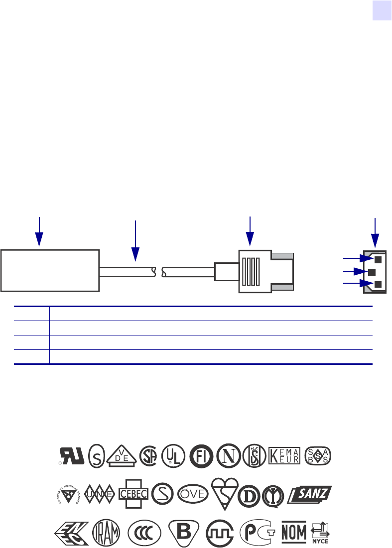
• The overall cord length must be less than 9.8 ft (3.0 m).
• The cord must be rated for at least 5 A, 250 V.
• The chassis ground (earth) must be connected to ensure safety and reduce electromagnetic
interference. The third wire in the power cord grounds the connection (Figure 11).
Figure 11 • Power Cord Specifications
• The AC power plug and the IEC 320 connector must bear the certification mark of at least
one of the known international safety organizations shown in Figure 12.
Figure 12 • International Safety Organization Marks
1AC power plug for your country
23-conductor HAR cable
3IEC 320 connector
4Contact view of plug—(a) neutral, (b) earth, (c) live
1 2 3 4
a
b
c
+
R
24 R110PA X 3 User Guide 9/7/2004 58981L-001 Rev. 1
Getting Started
Select a Communication Interface
Select a Communication Interface
The way that you connect your print engine to a data source depends on the communication
options installed in the print engine. See Data Ports on page 125 for control signal
descriptions and other additional information.
Standard Connections
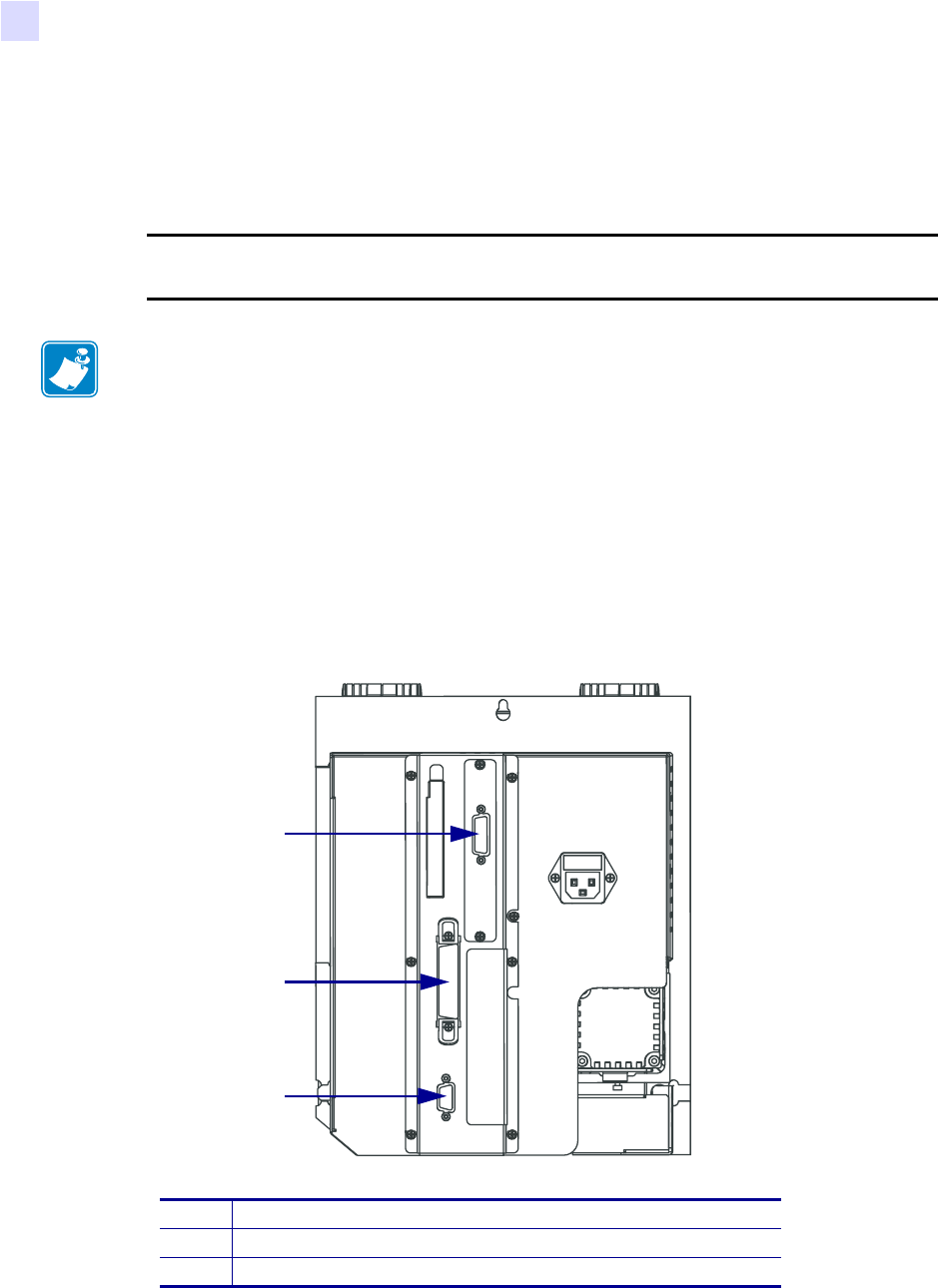
Refer to Figure 13. The print engine comes standard with both an Electronics Industries
Association (EIA) RS-232 serial interface (DB-9 connector) and an IEEE 1284 bi-directional
parallel interface. You may use either of these interface methods to send commands and label
formats from a host to the print engine.
Figure 13 • Cable Connections
Caution • Connecting a data communications cable while the power is ON may damage
the print engine.
Note • You must supply all interface cables for your application. Refer to Data Cable
Requirements on page 26 for specific cable requirements.
1DB-15 applicator interface port
2Parallel interface connector
3DB-9 serial interface connector
1
2
3

Getting Started
Select a Communication Interface
58981L-001 Rev. 1 9/7/2004 R110PAX3 User Guide 25
Optional Print Servers
• External ZebraNet PrintServer II (PSII). For more information on PSII, see the
PrintServer II User and Reference Guide (Zebra part number 45537L).
DB-15 Applicator Interface Connector
A DB-15 Applicator Interface Connector provides communication between the print engine
and the associated applicator hardware. In some applications, control signal timing may be a
critical element in the performance of the print engine.
System Considerations
Communications Code The print engine sends and receives American Standard Code for
Information Interchange (ASCII). This code consists of 128 characters (256 for Code Page
850) including uppercase and lowercase letters, numbers, punctuation marks, and various
control codes.
Interfaces The method of interfacing the print engine to a data source depends on the
communication options installed in the print engine and the host. The standard interfaces are
an RS-232 serial data port and an IEEE 1284 bi-directional parallel port.
Communication Specifications When communicating via an asynchronous serial data
port (RS-232), the baud rate, number of data and stop bits, the parity, and the XON/XOFF or
DTR control are user-selectable and should be set to match those of the host computer. When
communicating via the IEEE 1284 bi-directional parallel port, the previously mentioned
parameters do not apply. Refer to Print Engine Configuration on page 51 to configure the
communication parameters for the print engine.
Interface Considerations
RS-232 A serial communication method consisting of data and control signals; available as a
standard feature on most PCs and other hosts.
•Advantages: Cables and connectors are readily available from computer equipment stores
and suppliers; easy to connect; two-way communication between the host and the print
engine.
•Disadvantages: Slower than the parallel connection; limited to 50 feet (15.24 m) of cable.
IEEE 1284 Bi-directional Parallel A common communication method available on most
PCs and other hosts.
•Advantages: Fastest of the four communication interfaces; cables and connectors are
readily available from computer equipment stores and suppliers; two-way communication
between the host and the print engine; easy to connect.
•Disadvantages: Shorter recommended cable length of 6 feet (1.83 m); many computers
are equipped with only one parallel port, allowing only one IEEE 1284 bi-directional
device to be connected at a time.

26 R110PA X 3 User Guide 9/7/2004 58981L-001 Rev. 1
Getting Started
Select a Communication Interface
Data Cable Requirements
Data cables must be fully shielded and fitted with metal or metallized connector shells.
Shielded cables and connectors are required to prevent radiation and reception of electrical
noise.
To minimize electrical noise pickup in the cable:
• Keep data cables as short as possible.
• Do not bundle the data cables tightly with the power cords.
• Do not tie the data cables to power wire conduits.
Note • Print engines comply with FCC Rules and Regulations, Part 15, Subpart J, for Class A
equipment, using fully-shielded 6-foot (2-meter) data cables. Use of longer cables or
unshielded cables may increase radiated emissions above the Class A limits.
Getting Started
Types of Media
58981L-001 Rev. 1 9/7/2004 R110PAX3 User Guide 27
Types of Media
The print engine can use various types of media (Table 3). We strongly recommend the use of
Zebra-brand supplies for continuous high-quality printing. A wide range of paper,
polypropylene, polyester, and vinyl stock has been specifically engineered to enhance the
printing capabilities of the printer and to ensure against premature printhead wear.
Table 3 • Types of Media
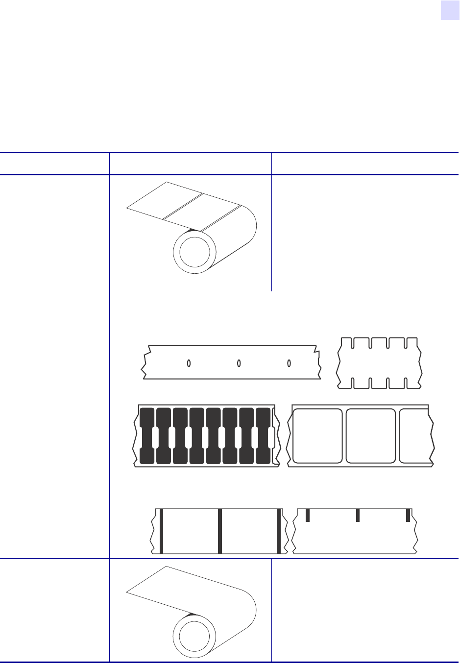
Media Type How It Looks Description
Non-Continuous Roll
Media
The media is wound on a core. Individual
labels are separated by a gap, notch, hole,
or black mark, which enables you to see
where one label ends and the next one
begins. When using media that has holes
or notches, position the media sensor
directly over a hole or notch. Figure 14
and Figure 15 show non-continuous web
and black mark media.
Figure 14 • Non-Continuous Web Media
Figure 15 • Non-Continuous Black Mark Media
Continuous
Roll Media
The media is wound on a core and is
without gaps, holes, notches, or black
marks. This allows the image to be printed
anywhere on the label.
28 R110PA X 3 User Guide 9/7/2004 58981L-001 Rev. 1
Getting Started
Types of Media
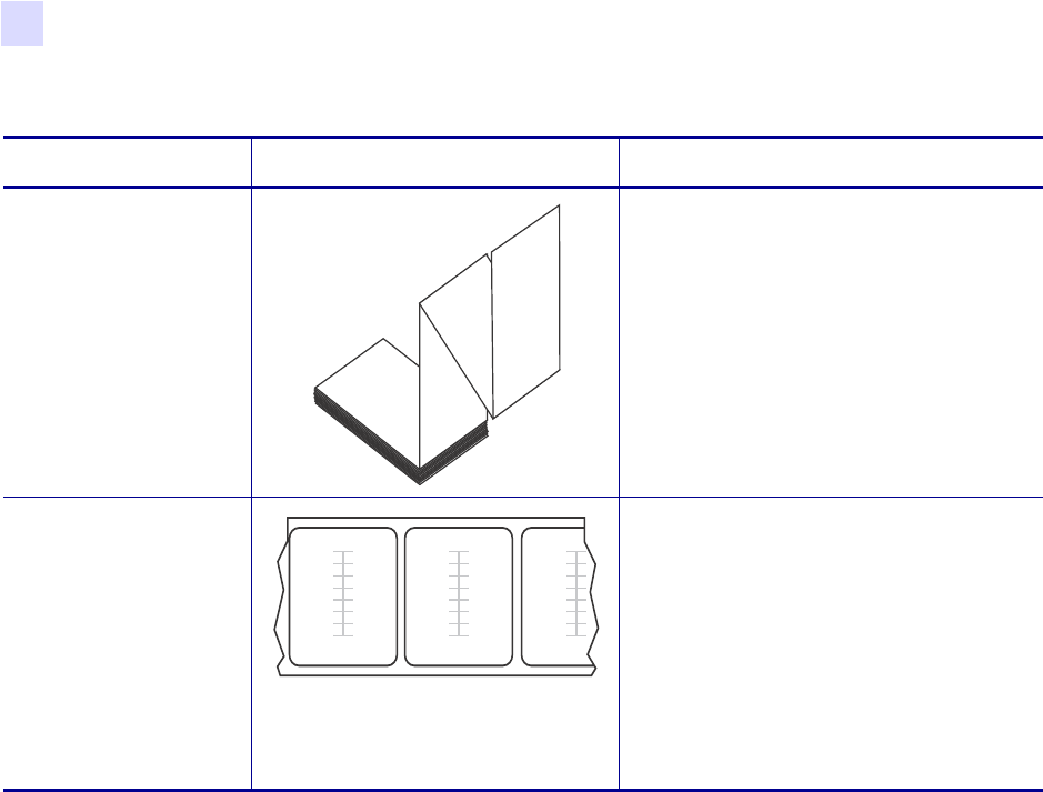
Fanfold Media The media is folded in a zigzag pattern.
RFID “Smart” Media
(for use with
RFID-capable print
engines only)
Each label has a radio frequency
identification (RFID) chip and antenna
inlay embedded between the label and the
liner. The media is made from the same
materials and adhesives as non-RFID
labels. The outline of the transponder
(which varies by manufacturer) can be
seen through the label. All “smart” labels
have memory that can be read, and many
have memory that can be encoded.
Table 3 • Types of Media (Continued)
Media Type How It Looks Description

Getting Started
Ribbon
58981L-001 Rev. 1 9/7/2004 R110PAX3 User Guide 29
Ribbon
Ribbon is a thin film that is coated on one side with wax or wax resin, which is transferred to
the media during the thermal transfer process. The media determines whether you need to use
ribbon and how wide the ribbon must be.
When ribbon is used, it must be as wide as or wider than the media being used. If the ribbon is
narrower than the media, areas of the printhead are unprotected and subject to premature wear.
When to Use Ribbon
Thermal transfer media requires ribbon for printing while direct thermal media does not.
To determine if ribbon must be used with a particular media, perform a media scratch test.
To perform a label scratch test, complete these steps:
1. Scratch the print surface of the media with your fingernail.
2. Did a black mark appear on the media?
Coated Side of Ribbon
Ribbon can be wound with the coated side on the inside or outside (Figure 16). This print
engine can only use ribbon that is coated on the outside. If you are unsure which side of a
particular roll of ribbon is coated, perform an adhesive test or a ribbon scratch test to
determine which side is coated.
Figure 16 • Ribbon Coated on Outside or Inside
If a black mark... Then the media is...
Does not appear on the media Thermal transfer. A ribbon is required.
Appears on the media Direct thermal. No ribbon is required, though
ribbon may be used to help protect the printhead
from abrasion with the media.
Outside Inside

30 R110PA X 3 User Guide 9/7/2004 58981L-001 Rev. 1
Getting Started
Ribbon
Adhesive Test
If you have labels or sticky tape available, perform the adhesive test to determine which side
of a ribbon is coated. This method works well for ribbon that is already installed.
To perform an adhesive test, complete these steps:
1. Peel a label from its liner.
2. Press a corner of the sticky side of the label to the outer surface of the roll of ribbon.
3. Peel the label off of the ribbon.
4. Observe the results. Did flakes or particles of ink from the ribbon adhere to the label?
Ribbon Scratch Test
If you do not have labels available, perform the ribbon scratch test. This method works best for
ribbon that is not installed.
To perform a ribbon scratch test, complete these steps:
1. Unroll a short length of ribbon.
2. Place the unrolled section of ribbon on a piece of paper with the outer surface of the
ribbon in contact with the paper.
3. Scratch the inner surface of the unrolled ribbon with your fingernail.
4. Lift the ribbon from the paper.
5. Observe the results. Did the ribbon leave a mark on the paper?
If ink from the ribbon... Then...
Adhered to the label The ribbon is coated on the outer surface.
Did not adhere to
the label
The ribbon is coated on the inner surface. To verify this,
repeat the test on the inner surface of the roll of ribbon.
If the ribbon... Then...
Left a mark on the paper The ribbon is coated on the outer surface.
Did not leave a mark on
the paper
The ribbon is coated on the inner surface. To verify this,
repeat the test on the other surface of the roll of ribbon.

58981L-001 Rev. 1 9/7/2004 R110PAX3 User Guide 31
3
Print Engine Operation
If you have completed the tasks and resolved issues in the checklist in Before You Begin
on page 14, use this chapter to load the print engine, to calibrate the print engine, and to print
configuration labels.
Contents
Load Media . . . . . . . . . . . . . . . . . . . . . . . . . . . . . . . . . . . . . . . . . . . . . . . . . . . . . . . . . . . 32
Load Ribbon. . . . . . . . . . . . . . . . . . . . . . . . . . . . . . . . . . . . . . . . . . . . . . . . . . . . . . . . . . . 38
Remove Used Ribbon . . . . . . . . . . . . . . . . . . . . . . . . . . . . . . . . . . . . . . . . . . . . . . . . . . . 43
Print a Configuration Label. . . . . . . . . . . . . . . . . . . . . . . . . . . . . . . . . . . . . . . . . . . . . . . . 44
Print a Network Configuration Label . . . . . . . . . . . . . . . . . . . . . . . . . . . . . . . . . . . . . . . . 45
Calibrate the Print Engine . . . . . . . . . . . . . . . . . . . . . . . . . . . . . . . . . . . . . . . . . . . . . . . . 46
Adjust Media Sensors . . . . . . . . . . . . . . . . . . . . . . . . . . . . . . . . . . . . . . . . . . . . . . . . . . . 48
Transmissive Media Sensor. . . . . . . . . . . . . . . . . . . . . . . . . . . . . . . . . . . . . . . . . . . . . 48
Reflective Media Sensor . . . . . . . . . . . . . . . . . . . . . . . . . . . . . . . . . . . . . . . . . . . . . . . 48
32 R110PA X 3 User Guide 9/7/2004 58981L-001 Rev. 1
Print Engine Operation
Load Media
Load Media
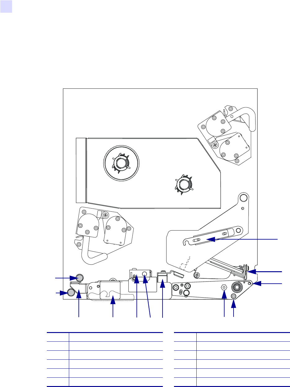
Figure 17 identifies the media-handling components. Figure 18 on page 33 shows the print
engine with media loaded.
Figure 17 • Components for Media Loading
1Printhead latch 7Pinch roller release button
2Printhead assembly 8Pinch roller assembly
3Peel bar 9Peel roller assembly
4Media liner roller 10 Peel roller latch
5Printhead locking pin 11 Lower guide post
6Media guide 12 Upper guide post
1
2
5
6
8
97
3
4
12
11
10
Print Engine Operation
Load Media
58981L-001 Rev. 1 9/7/2004 R110PAX3 User Guide 33
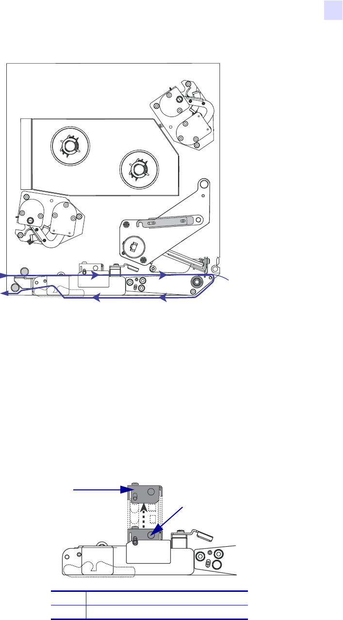
Figure 18 • Loaded Media
To load media, complete these steps:
1. Load media on the media supply reel of the applicator (refer to the applicator’s user
guide).
2. Open the media door.
3. See Figure 19. Press the release button on the pinch roller assembly, and allow the
assembly to pivot up.
Figure 19 • Opening the Pinch Roller
1Pinch roller assembly
2Pinch roller release button
2
1
34 R110PA X 3 User Guide 9/7/2004 58981L-001 Rev. 1
Print Engine Operation
Load Media
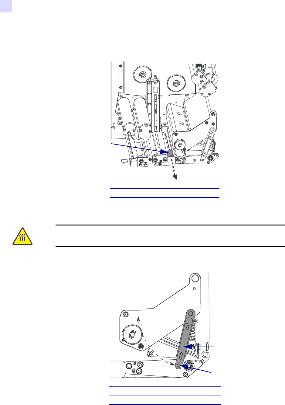
4. See Figure 20. Slide the outer media guide all the way out.
Figure 20 • Sliding the Outer Media Guide
5. See Figure 21. Open the printhead assembly by unlatching the printhead latch from the
locking pin.
Figure 21 • Opening the Printhead Assembly
1Outer media guide
Caution • The printhead may be hot and could cause severe burns. Allow the
printhead to cool.
1Printhead latch
2Locking pin
1
1
2
Print Engine Operation
Load Media
58981L-001 Rev. 1 9/7/2004 R110PAX3 User Guide 35
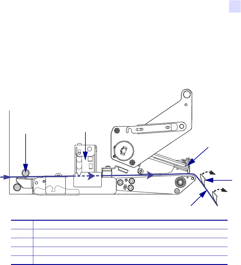
6. See Figure 22. Thread the media under the upper guide post, below the pinch roller
assembly, and under the printhead assembly.
7. See Figure 22. Extend approximately 30 in. (75 cm) of media past the peel bar. Remove
and discard the labels from this exposed media.
Figure 22 • Threading the Media
1Upper guide post
2Pinch roller assembly
3Printhead assembly
4Label
5Liner
1 2
3
4
5
36 R110PA X 3 User Guide 9/7/2004 58981L-001 Rev. 1
Print Engine Operation
Load Media
8. See Figure 23. Position the media so that it is aligned with and just touching the inner
media guide.
9. See Figure 23. Position the outer media guide so that it just touches the outer edge of the
media.
Figure 23 • Adjusting the Outer Media Guide
10. See Figure 19 on page 33. Press down on the pinch roller assembly until it locks closed.
11. See Figure 21 on page 34. Close the printhead assembly by rotating the printhead latch
until it latches onto the locking pin.
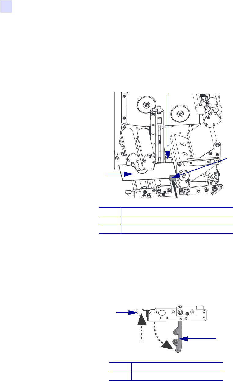
12. See Figure 24. Raise the peel roller latch so that the peel roller assembly pivots down.
Figure 24 • Releasing the Peel Roller Assembly
1Inner media guide
2Outer media guide
3Media
1Peel roller latch
2Peel roller assembly
1
2
3
1
2
Print Engine Operation
Load Media
58981L-001 Rev. 1 9/7/2004 R110PAX3 User Guide 37
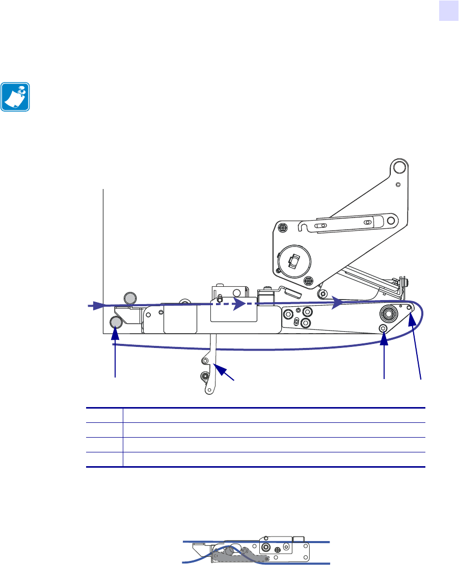
13. See Figure 25. Thread the media liner around the peel bar, under the media liner roller,
and through the peel roller assembly.
Figure 25 • Threading the Liner
14. See Figure 26. Rotate the peel roller assembly up until it locks into the closed position.
Figure 26 • Closed Peel Roller Assembly
15. See Figure 25. Thread the media liner past the lower guide post and around the take-up
spindle of the applicator (refer to the applicator’s user guide).
16. Close the media door.
Note • If the applicator has an air tube, route the media liner between the air tube and the
peel bar. Do not thread the media liner over the air tube.
1Lower guide post
2Peel bar
3Media liner roller
4Peel roller assembly
2 3 4
1
38 R110PA X 3 User Guide 9/7/2004 58981L-001 Rev. 1
Print Engine Operation
Load Ribbon
Load Ribbon
Use ribbon with thermal transfer media. The ribbon must be coated on the outside and wider
than the media. If the ribbon is narrower than the media, areas of the printhead are unprotected
and subject to premature wear.
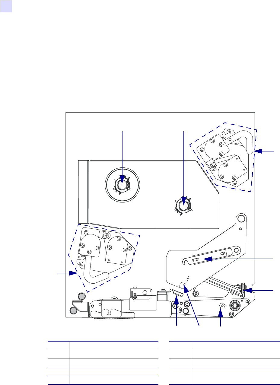
Figure 27 identifies the ribbon system components inside the media compartment of a
right-hand print engine. Figure 28 on page 39 shows the print engine with ribbon loaded.
Figure 27 • Components for Ribbon Loading
1Ribbon supply spindle 6Locking pin
2Ribbon take-up spindle 7Ribbon sensor
3Upper dancer assembly 8Ribbon sensor reflector
4Printhead latch 9Lower dancer assembly
5Printhead assembly
1 2
3
4
5
9
7
8 6
Print Engine Operation
Load Ribbon
58981L-001 Rev. 1 9/7/2004 R110PAX3 User Guide 39
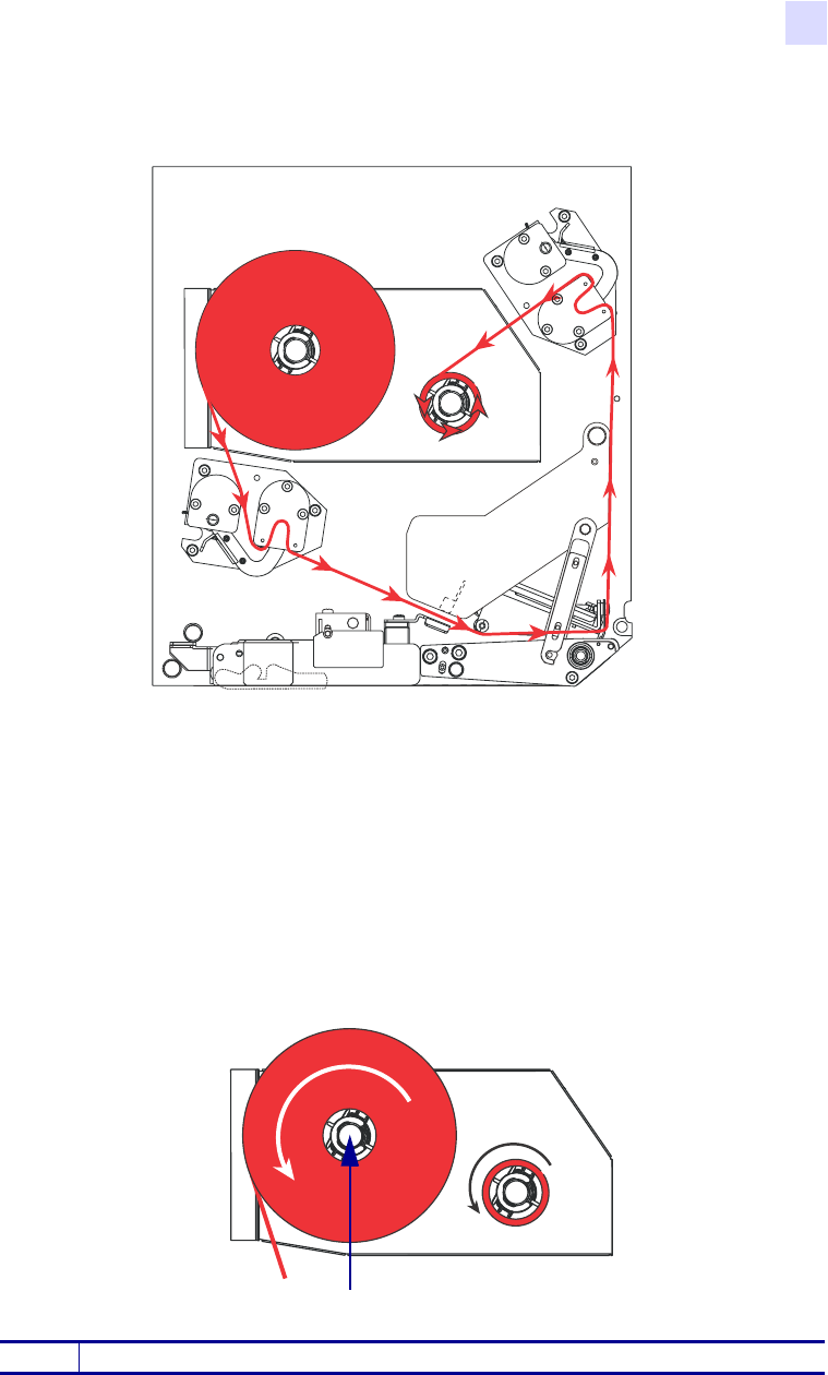
Figure 28 • Loaded Ribbon
To load ribbon, complete these steps:
1. See Figure 29. Place a full ribbon roll onto the ribbon supply spindle so the ribbon rotates
as shown, and then push the roll toward the print engine frame until it is fully seated.
Figure 29 • Placing Ribbon on the Ribbon Supply Spindle
1Ribbon supply spindle with media
1
40 R110PA X 3 User Guide 9/7/2004 58981L-001 Rev. 1
Print Engine Operation
Load Ribbon
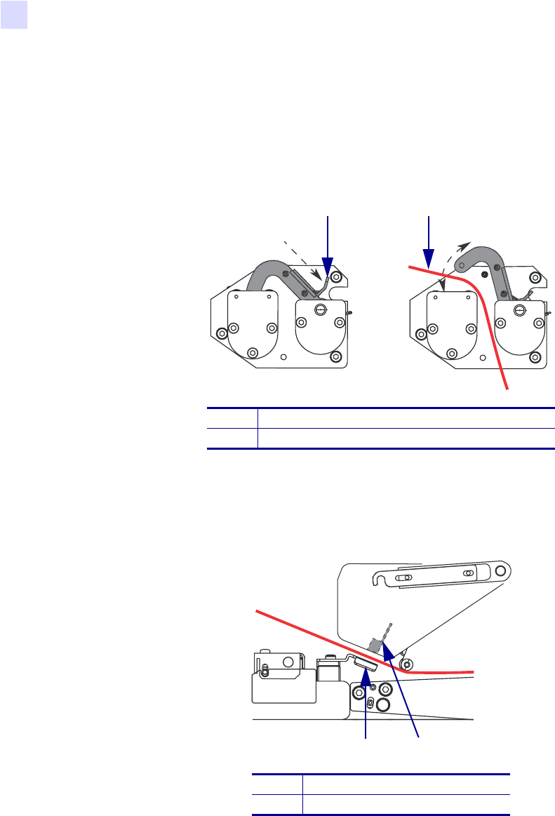
2. See Figure 30. On the lower dancer assembly, squeeze the opening tabs to pivot open the
dancer arm.
3. See Figure 30. Carefully thread the ribbon through the lower dancer assembly, and then
slowly release the dancer arm.
Figure 30 • Opening a Dancer Assembly
4. See Figure 31. Thread the ribbon between the ribbon sensor and the ribbon sensor
reflector.
Figure 31 • Ribbon Sensor
1Opening tabs
2Ribbon
1Ribbon sensor reflector
2Ribbon sensor
1 2
2
1