Zebra Technologies SPDR650 Short Pulse Digital Radar User Manual Users Guide
Zebra Technologies Corporation Short Pulse Digital Radar Users Guide
Users Guide
SPIDER-650
Short Pulse Digital RADAR
User’s Guide
M
MULTISPECTRAL
ULTISPECTRAL S
SOLUTIONS,
OLUTIONS, I
INC.
NC.
A Tradition of Excellence in Innovation
A Tradition of Excellence in Innovation
2
Note 1: General Conditions of operation (FCC 15.5)
This device complies with Part 15 of the FCC Rules. Operation is subject to the following two
conditions: (1) this device may not cause harmful interference, and (2) this device must accept
any interference received, including interference that may cause undesired operation.
Note 2: Modifications (FCC 15.21)
Changes or modifications to this equipment not expressly approved by Multispectral Solutions,
Inc. may void the user's authority to operate this equipment.
Note 3: Fields of Use (FCC 15.511 and 15.513)
Operation of this device is restricted to law enforcement, fire and rescue officials, scientific
research institutes, public utilities, commercial mining companies, construction companies
and industrial entities. Operation by any other party is a violation of 47 U.S.C. 301 and
could subject the operator to serious legal penalties.
3
Chapter 1 – INTRODUCTION
Overview
The SPIDER-650 is intended for determining the presence of objects that are within a 50-foot
line-of-sight of the unit. The unit has a resolution of 1 foot with a maximum range of 50 feet.
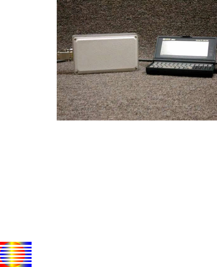
Installation
The SPIDER-650 unit can be placed anywhere as long as the antennae are facing outward
towards the open space of detection. The antennae are located on the side with the elevated
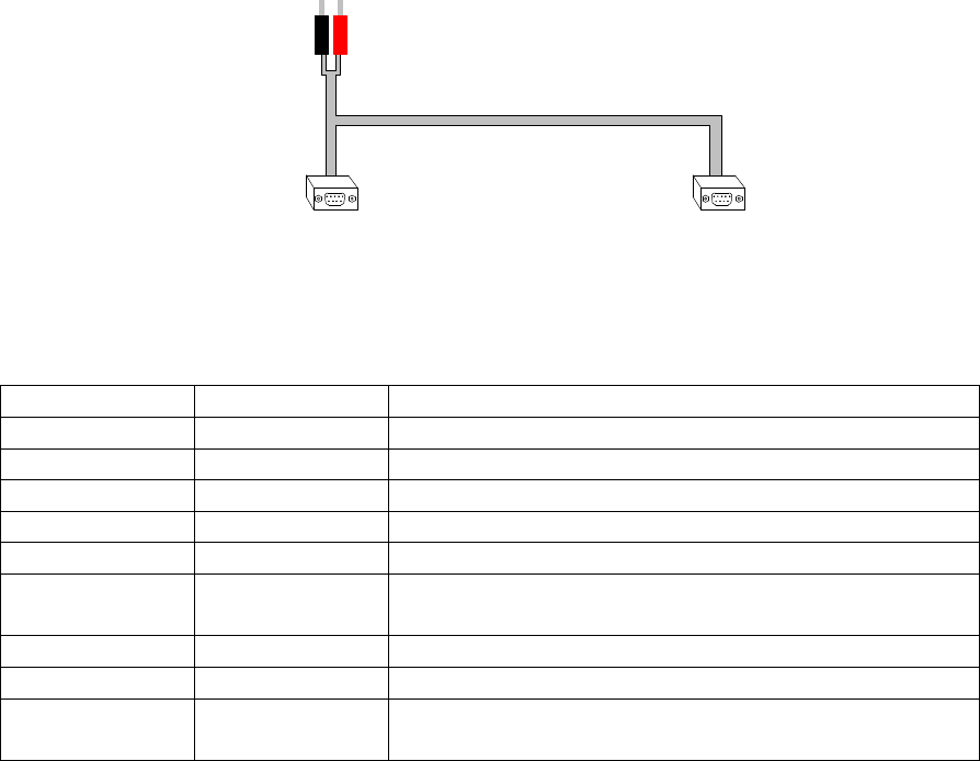
plastic facing. The only components required are an external cable (see Figure 1) and power
supply.
The cable should be 9-pin female on both ends with one end having two terminals for
distributing power to the SPIDER-650 unit. Figure 1 below shows banana leads as an example of
a way to use an external power supply as the source. Battery terminal leads may also be used to
power the unit as long as the battery can supply about 1 watt of power at its operating voltage
(see Table 1).
9-pin
Female
(to Terminal)
9-pin
Female
(to RADAR Unit)
Banana
Leads
(to Battery or
Power Supply)
Figure 1 - Communication / Power Cable
Table 1 - Pin Description of Terminal-Side 9-Pin Female
Pin Number Pin Name Description
1 GND Grounded
2 RD Received Data
3 TD Transmitted Data
4 N.C. No Connect
5 GND Grounded
6 Power Input DC Power – Approximately 200mA @ +5V.
Input DC Voltage can range from +3V to +30V.
7 N.C. No Connect
8 N.C. No Connect
9 Power Input DC Power – Approximately 200mA @ +5V.
Input DC Voltage can range from +3V to +30V.
4
Table 2 - Pin Description of RADAR-Side 9-Pin Female
Pin Number Pin Name Description
1 GND Ground
2 Serial_Out RS-232 Output
3 Serial_In RS-232 Input
4 GND Ground
5 GND Ground
6 POWER_IN Input DC Power – Approximately 200mA @ +5V.
Input DC Voltage can range from +3V to +30V.
7 Loop Connected to Pin 8
8 Loop Connected to Pin 7
9 POWER_IN Input DC Power – Approximately 200mA @ +5V.
Input DC Voltage can range from +3V to +30V.
15
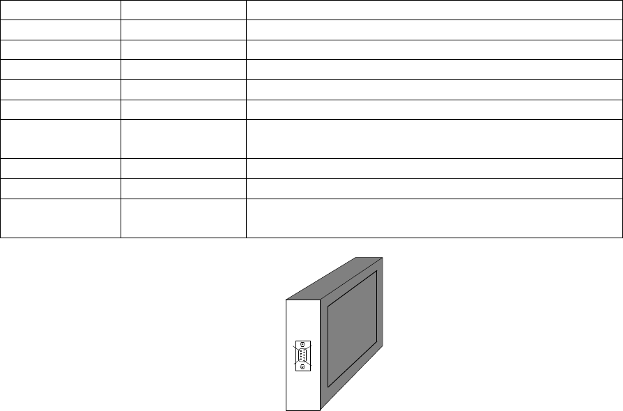
6 9
Figure 2 – Communication Port Location
Chapter 2 – BASIC SETUP
This chapter describes the process for setting up a terminal window on a user’s computer. The
below procedure assumes the user is running Windows 2000. Since other versions of Windows
may deviate slightly from the following procedure, the user should check the operating system
user’s manual for proper terminal setup procedures.
HyperTerminal Setup
To setup a HyperTerminal window under Windows 2000, adhere to the following procedure.
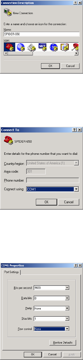
STEP 1:
Navigate to the Programs -> Accessories -> Communications folder and select the
HyperTerminal icon. You should see a window similar to the one shown in Figure 3. Type a
name for your HyperTerminal Session. The example below uses the “SPIDER-650” name. Once
you have typed a name, click the OK button.
5
Figure 3 - Connection Description Window
STEP 2:
Determine which serial port the SPIDER-650 unit is attached to and enter it in the “Connect To”
box shown below. Then click the OK button.
Figure 4 - Serial Port Selection
STEP 3:
You should see the Port Settings dialog box come up next. Enter the settings exactly as they
appear in Figure 5. Click the OK button when you are finished.
Figure 5 - Serial Port Settings
6
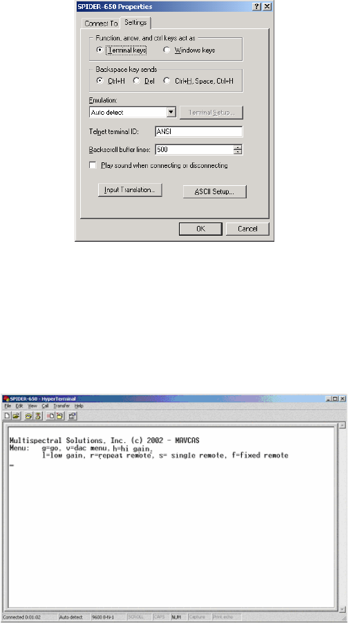
STEP 4:
Check the terminal settings window by navigating to the File -> Properties window and clicking
the Settings tab. Make sure the properties are exactly as they appear in Figure 6.
Figure 6 - Terminal Properties
Powering the Unit
Once the HyperTerminal setup is complete, applying power to the terminals will activate the
unit. The HyperTerminal window should appear similar to Figure 7. This figure shows what the
user will see in the HyperTerminal window on cycling power.
Figure 7 - Initial Terminal Screen after Applied Power
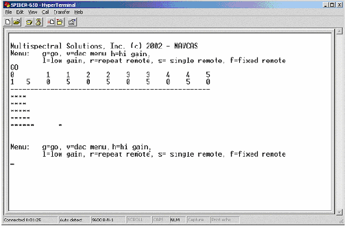
The screen displays the eight options available to the user. The most common option is the ‘g’
option. This will force the SPIDER-650 to transmit 5 consecutive pulses and recover and display
the respective returns. Each of the 5 series of 50 returns is captured using a different sensitivity
level on the receiver. Therefore, each row of asterisks on the HyperTerminal window displays a
set of 50 returns received at a certain sensitivity level. The rows are arranged such that the first
row of returns is captured at the least sensitive levels, while the last row of 50 returns is the most
sensitive of the set. This display is illustrated in Figure 8 showing a target found at bin 13 at the
7
most sensitive setting. Typing the character ‘g’ on the terminal’s keyboard will place the user in
this mode.
Figure 8 - Terminal Screen after Executing 'g' Menu Item
Aiming the Unit
For best results, the unit should be aimed so that the white-faced plastic front is perpendicular to
the line-of-sight between the unit and the target.
Chapter 3 – ADVANCED MENU OPTIONS
There are seven other advanced options available to the user if a custom software interface is to
be used.
DAC Menu Item
The DAC Menu is the menu that allows the user to change sensitivity levels on the SPIDER-
650’s internal DAC (digital-to-analog converter). If the user wishes to change one of the 5 bias
voltage values, he/she must first enter the ‘v’ key followed by the number corresponding to the
appropriate run number. For example, if the user wants to change the bias value for the third
transceiver run, a ‘v’ will be typed. This will bring up the following display:
select run number 1-5 , d = display voltages , q=end
enter voltage as 2 digit hex
Then the user hits the ‘3’ key and will see:
V3= 0x
show up on the terminal to indicate that the DAC value for the third run should be entered. This
is prompting the user to enter a 2 digit hex value between 0x00 and 0xFF. Only values after the
‘x’ should be entered.
8
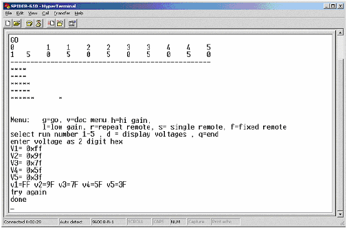
Once the values have been entered, the user must press the ‘q’ key to quit the menu and force
the current value to be set. If the programmed voltage levels need to be obtained, the user may
enter the ‘d’ key to display the currently programmed voltages (before hitting the ‘q’ key). After
typing the ‘d’ key, the user should expect to see a display similar to the following:
v1=10 v2=30 v3=60 v4=50 v5=90
done
An example DAC value modification terminal screen is shown in Figure 9.
Figure 9 - Terminal Screen After Entering the DAC Menu
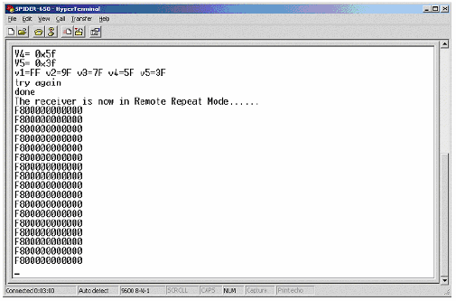
Repeat Remote Mode Menu Item
To enter the Repeat Remote Mode, the user enters an ‘r’ at the terminal’s keyboard in the main
menu. When the user enters Repeat Remote Mode, he will see a terminal similar to the following
(also shown in Figure 10):
The receiver is now in Remote Repeat Mode......
FC00000000000
FC00000000000
FC00000000000
FC00000000000
FE00000000000
FC00000000000
FC00000000000
FC00000000000
FC00000000000
.
.
.
This mode will start by setting the DAC to a decimal value of 127 (0x7f). To increase the
sensitivity on the receiver, the user will strike the ‘i’ key until the desired response is seen. The
‘i’ key has the effect of decreasing the DAC value by 1 LSB each time the key is struck.
9
To decrease sensitivity, the user will strike the ‘d’ key until the desired response is seen. The ‘d’
key has the effect of increasing the DAC value by 1 LSB each time the key is struck.
To leave this mode and return to the main menu, the user must press the escape key. When the
Escape key is hit, the following message will appear on the terminal indicating that the user
should enter one of the menu items:
Try Again
The display seen on the terminal in Figure 10 is in Packed Binary Target Format which is
described in APPENDIX B - PACKED BINARY TARGET RETURN FORMAT.
Figure 10 - Terminal Screen After Entering Repeat Remote Mode
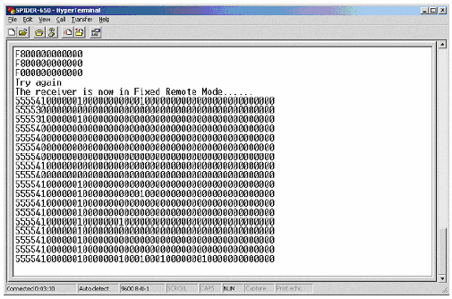
Fixed Remote Mode Menu Item
To enter the Fixed Remote Mode, the user enters an ‘f’ at the terminal’s keyboard in the main
menu. The Fixed Remote Mode allows the user to make decisions on where a target may be
based on a summation of five returns each at different sensitivity levels. When the SPIDER-650
enters Fixed Remote Mode, the user will see a terminal similar to what is shown in Figure 11.
The ASCII data seen at the terminal is in Packed BCD Target Return Format, which is described
in APPENDIX C - PACKED BCD TARGET RETURN FORMAT.
10
Figure 11 - Terminal Screen After Entering Fixed Remote Mode
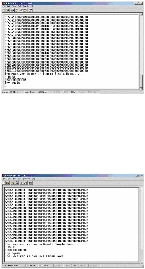
Single Remote Mode Menu Item
To enter the Single Remote Mode, the user enters an ‘s’ at the terminal’s keyboard in the main
menu. A response of “The receiver is now in Remote Single Mode…” will verify the user is in
this mode on the terminal (see Figure 12). The Single Remote Mode allows the user to find the
appropriate bias setting by entering a single DAC bias value and analyzing the return associated
with the bias setting. The return will be a single line of ASCII characters in Packed Binary
Target Format representing the target returns accumulated at the set bias level. In this mode, the
SPIDER-650 will remain idle until a ‘b’ is typed indicating to the SPIDER-650 that the user is
about to enter a bias value. At this point, the SPIDER-650 will prompt the user to enter two
digits by displaying the ‘=0x’ combination of characters. Once the two hexadecimal digits are
entered, the SPIDER-650 will send a single line of 13 ASCII characters representing the target
return in a packed binary format as described in APPENDIX B - PACKED BINARY TARGET
RETURN FORMAT.
The Escape key must be pressed twice to exit this mode. Once a return occurs, the user can then
exit this mode. Upon exiting the Single Remote Mode, the following message will appear on the
terminal indicating that the user should enter one of the menu items:
Try Again
11
Figure 12 – Sample Terminal Screen After Entering Single Remote Mode
Lo Gain Mode Menu Item
To place the SPIDER-650 in Lo Gain Mode, the user enters an ‘l’ at the terminal’s keyboard in
the main menu. The Lo Gain Mode allows the user to desensitize the receiver for environments
where the output transmit power is more than adequate for object detection. In this mode, the
user will see a message similar to the one at the bottom of Figure 13. The user will remain in LO
Gain Mode until HI Gain mode is entered (see next section).
Figure 13 – Sample Terminal Screen After Entering Lo Gain Mode
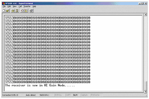
Hi Gain Mode Menu Item
To place the SPIDER-650 in Hi Gain Mode, the user enters an ‘h’ at the terminal’s keyboard in
the main menu. The Hi Gain Mode allows the user to use the full capability of the receiver for
environments where the targets have a limited radar cross section. In this mode, the user will see
a message similar to the one at the bottom of Figure 14. The user will remain in HI Gain Mode
until LO Gain mode is entered (see previous section).
12
Figure 14 – Sample Terminal Screen After Entering Hi Gain Mode
13
APPENDIX A -SPECIFICATIONS
Physical Characteristics:
Dimensions: 6.375 x 3.625 x 3.5 in (161.9 x 92.1 x 88.9 mm)
Weight: 16 oz.
Operating Temperature: 32 to 158 oF (0 to 70 oC)
Power Consumption (+5V Supply):
Normal Operation: 250 mA
Interface Standards:
RS-232/RS-485
Output Power:
FCC Part 15.511 and 15.513 Compliant
Sample Rate:
30 Hz
Frequency Range:
Centered at 6.35 GHz
Bandwidth:
500 MHz
Range:
50 feet
Resolution:
1 foot
Software Compatibility
Windows COM Port
14
APPENDIX B - PACKED BINARY TARGET RETURN FORMAT
The following sequence of numbers FC00000000000 characterizes target returns from 50 1-foot
range bins represented in a packed binary format. This format allows a simple form of data
compression to be processed in the SPIDER-650 unit while reducing the bottleneck of RS-232
data transfer. Each ASCII hexadecimal digit represents returns from four contiguous, 1-foot
range bins. The last ASCII hexadecimal digit will only represent the last two contiguous, 1-foot
range bins and will always be either 0, 8, 4, or C.
The most significant hexadecimal digits represent targets that are closer to the radar unit. For
example, let’s assume the following sequence of hexadecimal digits FC00000080000 were sent
over the RS-232 link and displayed on the terminal. The first hexadecimal digit ‘F’ (binary 1111)
designates that there were target returns at 1, 2, 3, and 4-foot intervals from the receiver since
each of the four bits were set in the respective range locations. The second hexadecimal digit ‘C’
(binary 1100) denotes there were target returns at 5 and 6 foot intervals from the receiver but
none were detected at the 7 and 8 foot intervals since these range locations have cleared bits. The
only other range location to be detected was at 33 feet since the 33rd bit from the left is the only
other one set (the hexadecimal 8 digit).
15
APPENDIX C - PACKED BCD TARGET RETURN FORMAT
The following sequence of numbers:
55220000000000000000000000000000000000000000000000
characterize a sample target return from 50, 1-foot range bins represented in a packed BCD
format. This format is a compact way of displaying the summation of returns at different
sensitivity levels from 5 consecutive target illuminations. Each ASCII digit represents a return
from a single 1-foot range bin. The most significant digit represents targets that are closer to the
radar unit. For example, let’s assume the above sequence of digits were sent over the RS-232
link and displayed on the terminal.
The first digit ‘5’ designates that there were target returns in the closest range bin at 1 foot away
for each of the 5 sensitivity settings. Range bins with a value of 5 are most likely target locations.
The third digit ‘2’ designates there were target returns at the 3-foot range bin for two of the 5
sensitivity settings. The user software will accumulate these returns over time and formulate
enough information to determine target locations.