Zebra Technologies TFF-1015-00AB WhereTag III (TFF-1015-00AB) User Manual TFF 1015 00AB UserMan 02 23 04
Zebra Technologies Corporation WhereTag III (TFF-1015-00AB) TFF 1015 00AB UserMan 02 23 04
UserMan
WhereNet Corp. June 2001 TFF-1015-00AB_UserMan_02_23_04.doc Page 1
WhereTag III
User’s Guide
Revision B, January 2004
Model Number: TFF-1015-00AB
WhereNet Corp.
2858 De La Cruz Blvd.
Santa Clara, CA 95050
408-845-8500
WWW.WhereNet.COM

WhereNet Corp. June 2003 TFF-1015-00AB_UserMan_02_23_04.doc Page 2
FCC Requirements
This device must operate in compliance with Federal Communications Commission (FCC) Rules and Regulations Parts
15. See FCC registration label, located on the bottom of the equipment for the FCC, registration.
This equipment has been tested and found to comply with the limits for both Class A and Class B devices, pursuant to Part
15 of the FCC Rules.
This ISM device complies with Canadian ICES-001.
Cet appareil ISM est conforme à la norme NMB-001 du Canada.
Radio Equipment Authorization: FCC ID: NSQTFF-1015-00AB
IC: 3586B-TFF1015
RF Notice
The internal antenna used for this transmitter must not be co-located or operating in conjunction with any other antenna or
transmitter.
Any changes or modifications to WhereNet Corp. equipment not expressly approved by WhereNet Corp. could void the
user’s authority to operate the equipment.
There are no user-serviceable parts inside. Do not attempt to open the unit to change batteries.
____________
_______________

WhereNet Corp. June 2003 TFF-1015-00AB_UserMan_02_23_04.doc Page 3
Contents
Introduction ...............................................................................................................4
Installation and Activation.........................................................................................7
Tag Mounting Options ...............................................................................................7
Specifications..............................................................................................................8

WhereNet Corp. June 2001 TFF-1015-00AB_UserMan_02_23_04.doc Page 4
Introduction
System overview
The WhereNet Real Time Locating System (RTLS) is designed to permit users to determine the position of tagged assets
in both indoor and outdoor facilities such as factories and freight yards. The system locates tagged assets by a process
involving redundant triangulation. Each tag autonomously emits a 2.4 GHz direct sequence spread spectrum (DSSS) radio
signal at predetermined blink rate. Each tag’s blink rate is randomized around its predetermined value to minimize the
number of collisions between transmissions made by different tags. The signal emitted by the tag is received by a
minimum of four Location Antennas. A typical transmission contains a preamble which is used to synchronize the
receiver, the tag’s serial number which identifies the tag, a status word which monitors various tag functions, data stored
in the tag’s memory and finally a CRC used to assure that the tag’s message is correct as received.
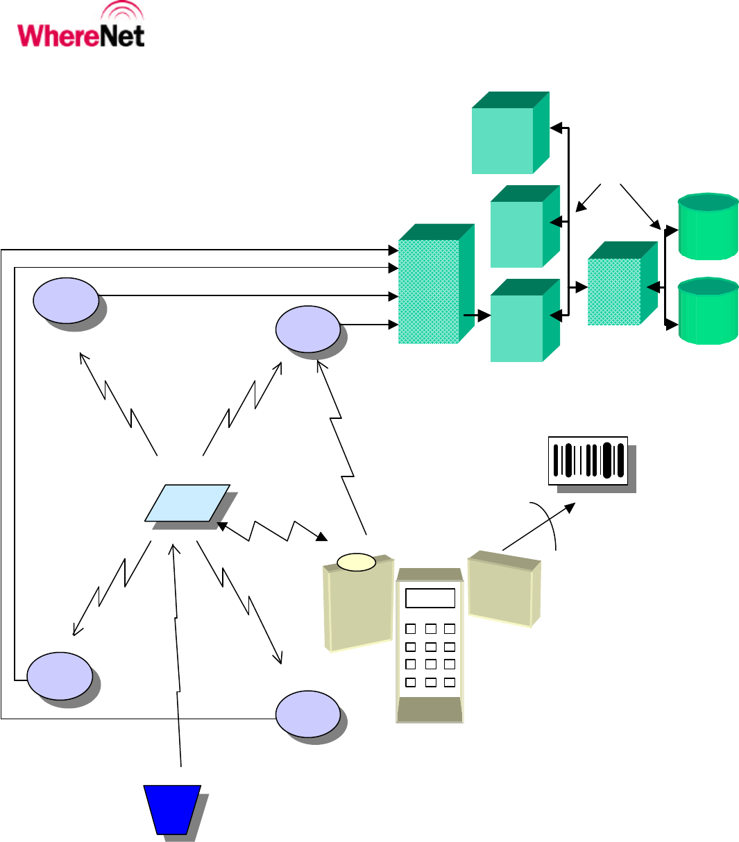
The principal components of WhereNet’s RTLS are shown in Figure 1.
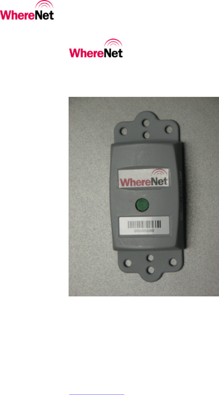
WhereTag III Device
The WhereTag III is the same as the existing WhereTag II with the exception that it has a 200 mW RF power amplifier added to boost
the RF ASIC’s power output from 2 mW to 60mW. The WhereTag III is the first level component of the WhereNet Real Time
Locating System (RTLS). It is a low-cost wireless device that attaches to a resource (such as an asset, pallet, container,
vehicle, etc.) and periodically broadcasts, via radio, it’s unique identification number. WhereNet’s RTLS infrastructure
detects that signal and precisely locates the tag and it’s associated resource.
Powered by a long-life internal battery, the WhereTag III’s beacon signal can be configured to “blink” from every half
second to once an hour. This allows some resources to be tracked second to second while others that are less mobile can
be tracked less frequently. At a typical blink rate of four minutes, the tag’s battery can last six years.
When excited by a WhereNet WherePort, a WhereTag III can alter its blink rate (typically faster) to enable more timely
location updates for critical threshold zones such as shipping/receiving docks and other portals.
Each WhereTag III has a unique identification number that is transmitted via radio during each blink. When it’s battery is
running low, the tag alerts the WhereNet RTLS infrastructure so that the tag can be proactively replaced. WhereTag IIIs
can be pre-programmed with 12 bytes of supplementary data (such as an asset or serial number) that can be included with
each blink. WhereTag IIIs are configured with WhereNet’s WhereWand.
The number is also printed as a Code 128 bar code on the tag. The bar code enables seamless integration with existing
inventory systems and delivers a cost effective total resource visibility solution that extends beyond the range of the
WhereNet Location Antennas.
WhereTags are extremely durable and can be used both indoors and outdoors. The tag’s case is resistant to oils, solvents
and hydraulic fluids.
WhereNet Location Antenna
This device is an active antenna that mounts remotely and is connected to the Location Processor. Its function is to
receive spread spectrum radio signals from the WhereTag devices. It converts the radio frequency signal to a lower
intermediate frequency and transfers those signals to the reader processor cards in the Location Processor.

WhereNet Corp June 2001 TFF-1015-00AB_UserMan_02_23_04.doc Page 5
WhereNet Location Processor
The WhereNet Location Processor is a processing unit that receives WhereTag device signals through a set of WhereNet
Location Antenna and calculates location information using sophisticated digital signal processing. The Location
Processor is able to track a large number of WhereTag devices simultaneously to assure location accuracy over a large
coverage area. The Location Processor forwards accurate location information, in real-time, to the WhereNet server,
where information can be graphically displayed, used for report generation or accessed through the Internet.
WhereNet Hand-Held Communicator or WhereWand
These devices allow the users to reconfigure the blink rate and 12 bytes of memory in a WhereTag.
WhereNet Corp. June 2001 TFF-1015-00AB_UserMan_02_23_04.doc Page 6
Figure 1. WhereNet Real Time
Locating System Block Diagram
Location
Antenna
GUI
Client
GUI
Client
RF
Client
and
Server
Location
Processor
2-way
communication
1-way spread
spectrum RF
1-way spread
spectrum RF for
sending tag ID
association with
bar code read
(Blink S/N &
telemetry) WhereTag III
WhereNet
Server
Indigenous
Network(s)
WhereNet
DBMS
Indigenous
MIS
DBMS
HPC
Bar
WhereWand
PCMCIA Scanner
Code
Laser bar code
scanner
WherePort
1-way FSK
Magnetic Field
Dimensions:
* Location Antenna – Location Antenna = 1000 ft indoor
* WhereTag III – Location Antenna = 1000 ft indoor
* WhereTag II - WhereWand = 1-2 ft
* WherePort- WhereTag III = 25 ft
Location
Antenna
Location
Antenna
Location
Antenna

WhereNet Corp June 2001 TFF-1015-00AB_UserMan_02_23_04.doc Page 7
Tag Installation and Activation
Tags are shipped with all radio emitters deactivated. Prior to installing a tag on an item to be tracked, the tag must be
activated. This is done using the WhereNet’s WhereWand. The WhereWand is used to configure and activate the tag, and
to confirm that the tag is properly configured and operational. The detailed procedure for tag activation is covered in
WhereWand User’s Manual.
Tag Mounting Options
Introduction
The WhereTag III device has a variety of ways to be mounted depending on the user’s needs. The following mounting
methods can be used:
Built-in mounting ears for screws, rivets (ears are removable).
Tie wrap
Poly-lock
Adhesive tape
Vehicle rearview mirror mount
Trailer and ISO container mounts

WhereNet Corp June 2001 TFF-1015-00AB_UserMan_02_23_04.doc Page 8
Specifications (Subject to change without notice)
WhereTag III (Model #: TFF-1015-00AB)
CAPABILITIES
Frequency Range................................................2.4 to 2.483 GHz
Typical Read Range, Indoors............................175 m (600 ft)
Typical Read Range, Outdoors .........................1500 m (4500 ft)
User Configurable Blink Rate............................5 sec to 9 hr
WherePort Range................................................7.5 m (25 ft) (With WherePort set for maximum power and optimum orientation.)
TAG MOUNTING OPTONS
Built-in mounting ears for screws, rivets (ears are removable)
Tie wrap
Poly-lock
Adhesive tape
Vehicle rearview mirror mount
Trailer and ISO container mounts
ELECTRICAL
Power.....................................................................AA 3.6V Lithium Thionyl Chloride cell (The battery is not replaceable.)
Typical Battery Life.............................................7 years (dependent on blink rate and operating temperature)
ENVIRONMENTAL / PHYSICAL
Operating Temperature Range ..........................-40º C to +65º C (-40º F to +149º F)
Storage Temperature Range ..............................-40º C to +70º C (-40º F to +158º F)
Durability..............................................................1.8 m (6 ft) drop to concrete
Height....................................................................2.1 cm (0.9 in)
Length, without mounting tabs.........................6.6 cm (2.6 in)
Length, with mounting tabs...............................10.5 cm (4.1 in)
Width ....................................................................4.4 cm (1.7 in)
Weight ..................................................................58 g (2.0 oz)
Environmental Sealing........................................IP67 (dust tight, immersible)
Case Material.......................................................Molded Plastic (Food-grade polyester blend)
REGULATORY APPROVALS
- FCC Part 15 Class B, EN 55022 Class B, EN 55024, TUV GS per EN 60590, R&TTE Directive 99/5/EC.
- ANSI/INCITS 371.3