Zebra Technologies VC6000 Vehicle and Office Terminal with BT User Manual Quick Ref Guide VC6000 Series
Zebra Technologies Corporation Vehicle and Office Terminal with BT Quick Ref Guide VC6000 Series
UserManual.wiki
>
Zebra Technologies
>
VC6000 User Manual
User Manual
Navigation menu
Upload a User Manual
Namespaces
Wiki Guide
HTML
PDF
Info
Views
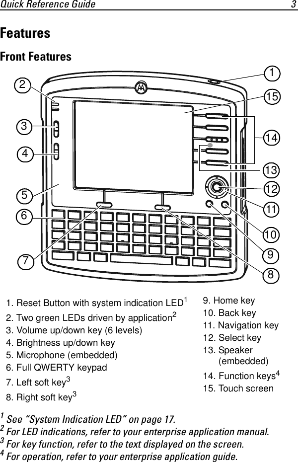
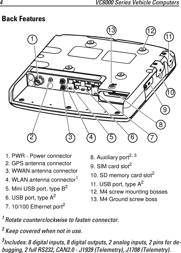
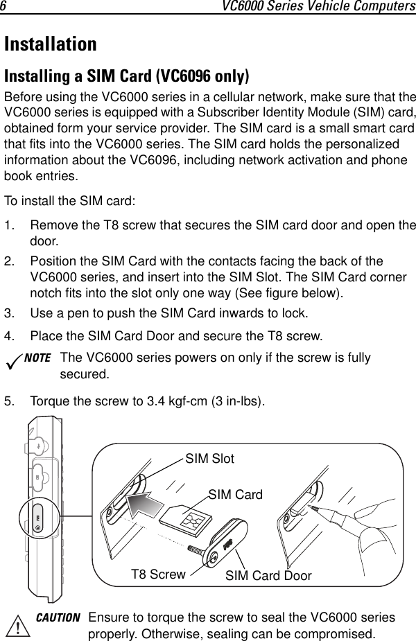
User Manual
Discussion / Help
Navigation