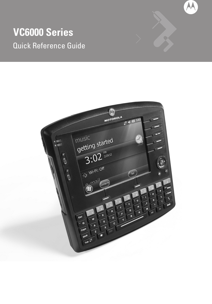
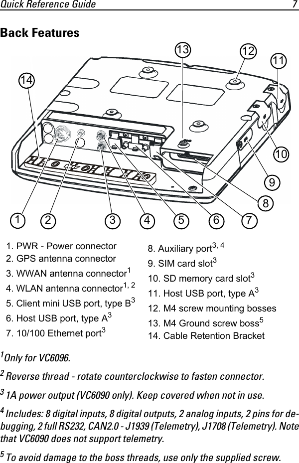
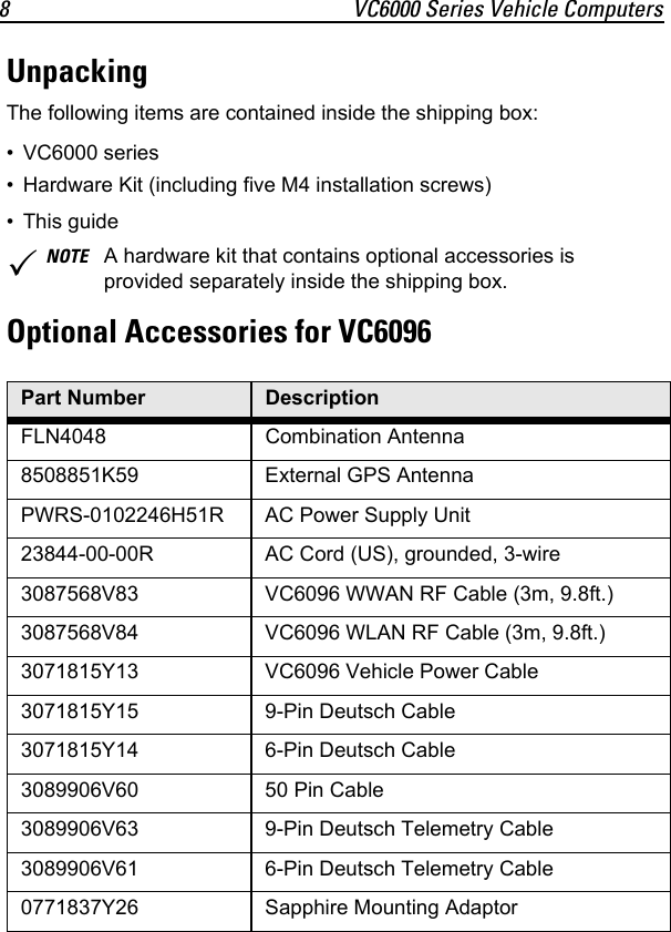
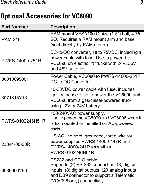
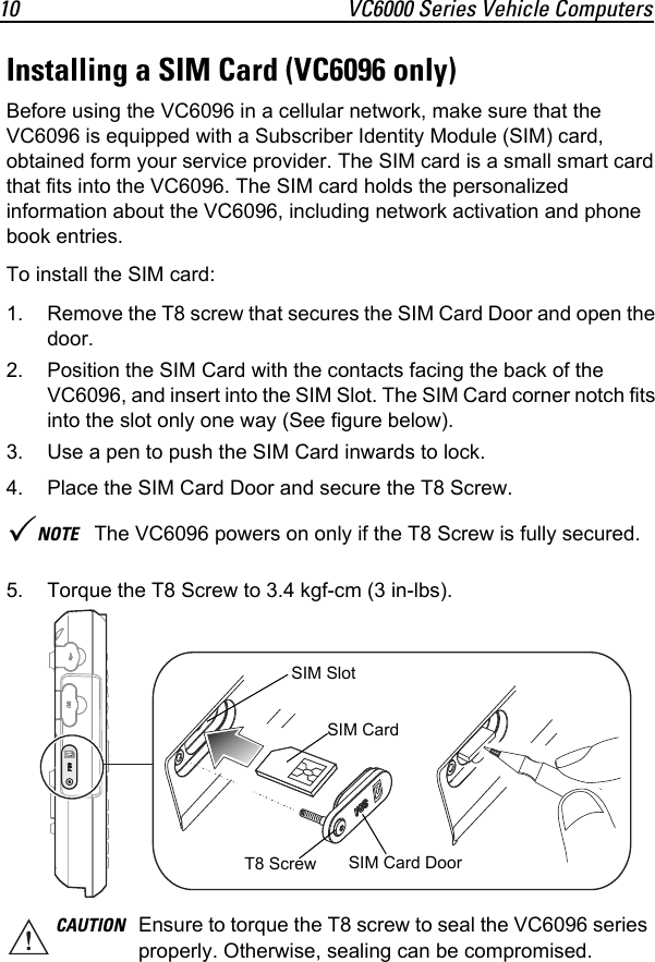
Zebra Technologies VC6090 Vehicle Computer User Manual VC6000 Series Quick Reference Guide

Zebra Technologies Corporation Vehicle Computer VC6000 Series Quick Reference Guide

User manual

VC6000 SeriesQuick Reference Guide
© 2012 by Motorola Solutions, Inc. All rights reserved.No part of this publication may be reproduced or used in any form, or by any electrical or mechanical means, without permission in writing from Motorola. This includes electronic or mechanical means, such as photocopying, recording, or information storage and retrieval systems. The material in this manual is subject to change without notice.The software is provided strictly on an “as is” basis. All software, including firmware, furnished to the user is on a licensed basis. Motorola grants to the user a non-transferable and non-exclusive license to use each software or firmware program delivered hereunder (licensed program). Except as noted below, such license may not be assigned, sublicensed, or otherwise transferred by the user without prior written consent of Motorola. No right to copy a licensed program in whole or in part is granted, except as permitted under copyright law. The user shall not modify, merge, or incorporate any form or portion of a licensed program with other program material, create a derivative work from a licensed program, or use a licensed program in a network without written permission from Motorola. The user agrees to maintain Motorola’s copyright notice on the licensed programs delivered hereunder, and to include the same on any authorized copies it makes, in whole or in part. The user agrees not to decompile, disassemble, decode, or reverse engineer any licensed program delivered to the user or any portion thereof. Motorola reserves the right to make changes to any software or product to improve reliability, function, or design.Motorola does not assume any product liability arising out of, or in connection with, the application or use of any product, circuit, or application described herein.No license is granted, either expressly or by implication, estoppel, or otherwise under any Motorola, Inc., intellectual property rights. An implied license only exists for equipment, circuits, and subsystems contained in Motorola products.Motorola Solutions, Inc. 1301 E. Algonquin Rd. Schaumburg, IL 60196-1078, U.S.Awww.motorolasolutions.comWarrantySubject to the terms of Motorola’s hardware warranty statement, the VC6000 series products are warranted against defects in workmanship and materials for a period of one year from the date of shipment. For the complete Motorola hardware product warranty statement, go to: www.motorola.com/enterprisemobility/warranty.
Quick Reference Guide 1IntroductionThe Motorola VC6000 series is a rugged vehicle computer, specifically designed for the harsh conditions of the mobile environment.The VC6000 series enables real-time data access, collection, capture and report of information related to the driver’s workflow, status and location.The VC6000 series offers low width and height and thin design for minimal driver obstruction and maximum space utilization. It has a rugged construction: IP64-sealed, aluminum rear housing and MIL-STD-810F military ratings. The unit is designed to withstand the most extreme environments including lift truck mounting use cases.The VC6000 series offers programmable navigation keys with tactile feedback and QWERTY keyboard with large keys ideal for gloved hands, all backlit.Data can be entered using the touch-screen, built-in keyboard or an external bar code scanner.Cellular and Wi-Fi radios are used to exchange voice and data with wide and local area networks.BluetoothTM technology is used for cordless connection of peripheral devices such as printers, bar code scanners, handsfree speakers and headsets.Among its many communication interfaces, the VC6096 model contains an internal Global Positioning System (GPS) receiver, ensuring reliable and accurate vehicle location. The VC6000 series offers light weight flexible mounting with VESA100 compatibility.The VC6090 comes with pre-loaded, Pre-licensed Terminal Emulation for out-of-the-box terminal emulation solution.The VC6090 is MSP compatible with easy and cost-effective centralized remote management.The VC6000 series provides USB connectivity with two USB host ports to connect a corded bar code scanner and for a service flash memory stick. Another USB Client port is provided for ActivSync.
2 VC6000 Series Vehicle ComputersIt also provides RS232 and GPIOs connectivity with two RS232, 8 Digital Inputs, 8 Digital Outputs and 2 Analog Inputs for building flexible solutions.While the VC6090 model includes internal antennas, the VC6096 model external antennas and other accessories require a professional installation, performed by trained and licensed personnel. For proper installation requirements, contact your professional installer, VAR, or antenna manufacturer.
Quick Reference Guide 3About this GuideThis guide contains the following:•Model Configurations on page 4•Features on page 6•Unpacking on page 8•Optional Accessories for VC6090 on page 9•Optional Accessories for VC6090 on page 9•Installing a SIM Card (VC6096 only) on page 10•Installing the SD Memory Card on page 11•Mounting on page 12•Operating the VC6000 series on page 25•Troubleshooting on page 28•Regulatory Information on page 28For more information, refer to the VC6000 series Product Reference Guide, p/n 6802986C08-x available at: www.motorola.com/enterprisemobility/manuals.
4 VC6000 Series Vehicle ComputersModel ConfigurationsThis guide covers the configuration of the following VC6000 series models:The VC6000 series features:• Ergonomic design with a color LCD touch screen• Windows Mobile 6.5 operating system• Internal Bluetooth radio to enable wireless connection to a Bluetooth printer, bar code scanner, headset and other Bluetooth peripherals• Connection to WLAN in 802.11a/b/g standards (VC6090 and VC6096)• Connection to WWAN using a Global Positioning System (GSM) for mobile communication, cellular radio and High-Speed Downlink Packet Access (HSDPA) (VC6096 only)• 10/100 Ethernet port for connection to Local Area Network (LAN) • Vehicle motion and location detection via the vehicle telemetry and the GPS receiver (VC6096 only)• Serial RS232 interface and GPIOs• Two full speed USB ports (One with 1A power output, VC6090 only)Configuration   Model VC6000 VC6096 VC6090Operating System Windows Mobile 6.5 ClassicWindows Mobile 6.5 ProfessionalWindows Mobile 6.5 ClassicGPS No Yes NoBluetooth (BT) Yes Yes YesWireless LAN No Yes (802.11 a/b/g) Yes (802.11 a/b/g)Cellular radio(HSDPA, UMTS, GSM, GPRS, EDGE)No Yes (Voice and data)NoVehicle Telemetry No Yes  No Internal BT Antenna Yes Yes  Yes Internal WLAN Antenna No No Yes
Quick Reference Guide 5• Flexible power options:- Direct 10V to 33Vdc, with ignition sense for gas/diesel-powered lift trucks and vehicles with 12V or 24V battery. - External 18 to 75V DC-to-DC converter for electric-powered lift truck with 24V, 36V or 48V battery (VC6090 only).- External 100 to 240VAC power supply for AC-powered carts and sta-tionary installation.• Reliable operation in cold environments, as low as -20 °C (- 4 °F)• Maximum operational temperature 60 °C (140 °F)
6 VC6000 Series Vehicle ComputersFeaturesFront Features1 See “System Indication LED” on page 25.2 For LED indications, refer to your enterprise application guide.3 VC6090 numeric keys also marked as F1-F20 function keys (with Ctrl / Alt keys)4 For key function, refer to the text displayed on the screen.5 Model VC60x0-Home key. Model VC6096-Call key (For Home, press Fn+H keys).6 Model VC60x0-Back key. Model VC6096-End key (For Back, press Fn+J keys).7 For keys operation, refer to your enterprise application guide.1. Power Button with System Indication LED12. Two green LEDs driven by application23. Volume up/down key (6 levels)4. Brightness up/down key 5. Microphone6. Full QWERTY keypad 37. Left soft key48. Right soft key49. Call or Home key510. End or Back key611. Navigation key12. Select key13. Speaker (embedded)14. Function keys715. Touch screen248967311121351014151
Quick Reference Guide 7Back Features1Only for VC6096.2 Reverse thread - rotate counterclockwise to fasten connector.3 1A power output (VC6090 only). Keep covered when not in use.4 Includes: 8 digital inputs, 8 digital outputs, 2 analog inputs, 2 pins for de-bugging, 2 full RS232, CAN2.0 - J1939 (Telemetry), J1708 (Telemetry). Notethat VC6090 does not support telemetry.5 To avoid damage to the boss threads, use only the supplied screw.1. PWR - Power connector2. GPS antenna connector3. WWAN antenna connector14. WLAN antenna connector1, 25. Client mini USB port, type B36. Host USB port, type A37. 10/100 Ethernet port38. Auxiliary port3, 49. SIM card slot310. SD memory card slot3 11. Host USB port, type A312. M4 screw mounting bosses13. M4 Ground screw boss514. Cable Retention Bracket 6871121343109115214
8 VC6000 Series Vehicle ComputersUnpackingThe following items are contained inside the shipping box:• VC6000 series• Hardware Kit (including five M4 installation screws)• This guideOptional Accessories for VC6096NOTE A hardware kit that contains optional accessories is provided separately inside the shipping box.Part Number DescriptionFLN4048 Combination Antenna8508851K59 External GPS AntennaPWRS-0102246H51R AC Power Supply Unit23844-00-00R AC Cord (US), grounded, 3-wire3087568V83 VC6096 WWAN RF Cable (3m, 9.8ft.)3087568V84 VC6096 WLAN RF Cable (3m, 9.8ft.)3071815Y13 VC6096 Vehicle Power Cable3071815Y15 9-Pin Deutsch Cable3071815Y14 6-Pin Deutsch Cable3089906V60 50 Pin Cable3089906V63 9-Pin Deutsch Telemetry Cable3089906V61 6-Pin Deutsch Telemetry Cable 0771837Y26 Sapphire Mounting Adaptor
Quick Reference Guide 9Optional Accessories for VC6090Part Number DescriptionRAM-246URAM mount VESA100 C-size (1.5") ball, 4.75 SQ. Requires a RAM mount arm and base (sold directly by RAM mount).PWRS-14000-251RDC-to-DC converter, 18 to 75VDC, including a power cable with fuse. Use to power the VC6090 on electric lift trucks with 24V, 36V and 48V batteries.30013095001 Power Cable, VC6090 to PWRS-14000-251R DC-to-DC Converter 3071815Y1310-33VDC power cable with fuse, includes ignition sense. Use to power the VC6090 and VC6096 from a gas/diesel-powered truck using 12V or 24V battery.PWRS-0102246H51R100-240VAC power supply.Use to power the VC6090 and VC6096 when it is fix mounted or installed on AC-powered carts. 23844-00-00RUS AC line cord, grounded, three wire for power supplies PWRS-14000-148R and PWRS-14000-241R as well as PWRS-0102246H51R3089906V60RS232 and GPIO cableSupports (2) RS-232 connection, (8) digital inputs, (8) digital outputs, (20 analog inputs and DB9 connector to support a Telematic (VC6096 only) connectivity.
10 VC6000 Series Vehicle ComputersInstalling a SIM Card (VC6096 only)Before using the VC6096 in a cellular network, make sure that the VC6096 is equipped with a Subscriber Identity Module (SIM) card, obtained form your service provider. The SIM card is a small smart card that fits into the VC6096. The SIM card holds the personalized information about the VC6096, including network activation and phone book entries.To install the SIM card:1. Remove the T8 screw that secures the SIM Card Door and open the door.2. Position the SIM Card with the contacts facing the back of the VC6096, and insert into the SIM Slot. The SIM Card corner notch fits into the slot only one way (See figure below).3. Use a pen to push the SIM Card inwards to lock.4. Place the SIM Card Door and secure the T8 Screw.5. Torque the T8 Screw to 3.4 kgf-cm (3 in-lbs).NOTE The VC6096 powers on only if the T8 Screw is fully secured.CAUTION Ensure to torque the T8 screw to seal the VC6096 series properly. Otherwise, sealing can be compromised.SIM Card SIM Slot SIM Card DoorT8 Screw
Quick Reference Guide 11Installing the SD Memory CardA Secure Digital (SD) memory card provides secondary non-volatile data storage. Up to 32GB memory cards can be used. The card slot is located on the side panel of the VC6000 series.To install the SD memory card:1. Lift up the Protective Rubber Cap that covers the Memory Card Slot.2. Position the SD Memory Card with the contacts facing the back of the VC6000 series and insert into the Memory Card Slot. The corner notch of the SD Memory Card fits into the Memory Card Slot only one way.3. Use your pen to push the SD Memory Card inwards to lock. 4. Replace the Protective Rubber Cap to seal the Memory Card Slot.SD Memory CardProtective Rubber CapMemory Card Slot
12 VC6000 Series Vehicle ComputersMountingThe following mount examples should be used for installing the VC6000 series inside the vehicle. For optional mounting instructions, refer to the documentation provided by the mount manufacturer. Recommended mount manufacturer: RAM Mounts.Free-standing Pedestal MountThe mount allows the VC6000 series to be easily readjusted to either the driver or passenger sides in the most comfortable location. A single adjustment knob enables simultaneous adjustment of both upper and lower ball joints. The mount affixes to the VC6000 series using the M4 screws, spring and flat washers and bushings included inside the Hardware kit, and to the vehicle’s dashboard using self tapping screws or bolts, provided by the mount manufacturer.WARNING!Vehicles equipped with air bags - An air bag inflates with great force. DO NOT install the VC6000 series or place objects, including other communication equipment, in the area over the air bag or in the air bag deployment area. If the communication equipment is improperly installed and the air bag inflates, this could cause serious injury.CAUTION The VC6000 series are supplied with four M6 stainless screws with flat and lock washers and a ground screw. Do not use non-metric screws to avoid damaging the screw threads resulting in housing damage.RAdjustment KnobRAM-246U(x4)
Quick Reference Guide 13Desk MountThe mount allows the VC6000 series to be easily placed on a desk and adjusted to a most comfortable screen view position. A single adjustment knob enables adjustment of both upper and lower ball joints simultaneously. The mount affixes to the VC6000 series using the M4 screws, spring and flat washers and bushings included inside the Hardware Kit.Lift TrucksUse RAM Mount RAM-246U and RAM-247U-25 Rail Clamp Base or alternative to install the VC6090 on the front arm of the electric lift truck.Secure the VC6090 RAM-246U with four RAM-246U Screws supplied with the VC6090.Install a RAM Clamp Base to one of the roll cage uprights on the electric lift truck by securing the bolts around one of the uprights using the correct mounting hardware. Horizontal Orientation — Square Upright Mounting ExampleNOTE An alternative RAM base may be used may be used to install the VC6090.NOTE Avoid using horizontal mounting with arms longer than RAM-201U to minimize amplification to lift truck vibration.RAM-246U(x4)RRRAM-246U(x4)UprightRAM-247U-25 Rail Clamp Base (or alternative)
14 VC6000 Series Vehicle ComputersGuidelines for Routing Cables• Establish a neat route for the cable, staying clear of moving parts or hot surfaces.• Fix the cable to an existing cable runs inside the vehicle using cable ties.• When the cabling must go through a panel, use a suitable cable guard.• When fixing a conduit or a cable on the outside of a vehicle, use P-Clips. Either drill and tap the hole or use a nut and bolt to secure the clip.• Ensure the cable does not have tight bends. The minimum recom-mended radius is 6.35 cm (2.5 inches).• Ensure cables do not swing or chafe on the structure. This often requires using cable ties approximately every one foot, and ensuring the cables do not flex often, especially where they connect to the VC6000 series.• If you must re-position the VC6000 series occasionally, ensure there is enough slack in the cable to accommodate movement without putting tension on the cable.• Use plastic cable ties to secure the cables to the Cable Tie Bracket of the VC6000.• Connect the power as close to the battery as possible, but not directly from the battery terminals, and not before any main fuse.• On gasoline, diesel or propane electric lift trucks, connect the power as close to the battery terminals as possible, and avoid using existing wir-ing.• Ensure that the fuse is as close as possible to the power source.• The fuse must be securely mounted and in an accessible location.• Do not install where the cable will be a trip hazard or interfere with safety of day-to-day activities or otherwise create a hazardous condi-tion.Cable Tie Bracket
Quick Reference Guide 15• Fix the cable to existing cable runs inside the electric lift truck using cable ties, but make sure they are away from any moving or hot sur-faces.• If the VC6090 needs to be re-positioned, be sure there is enough slack in the cable to accommodate movement without putting tension on the cable.• DO NOT wind a cable in and out of the mesh on a cage.• DO NOT route the cables on the outside of the electric lift truck or areas where the electric lift truck may come in contact with objects.Mounting the VC6000 Series on Gas/Diesel-PoweredVehiclesDirect 10V to 33Vdc, with ignition sense for gas/diesel-powered lift trucks and vehicles with 12V or 24V battery. Connecting the Vehicle Power CableTo connect the power cable:1. Disconnect the power terminals from the vehicle battery.2. Connect the black wire to the vehicle’s negative power source.3. Connect the green wire to the vehicle’s ignition switch.WARNING: Shortening or modifying the cable and/or by-passing the in-line fuse voids the product warranty, nullifies the product UL safety mark, and may result in a hazardous condition. Do not modify the cable under any circum-stance.CAUTION DO NOT install the VC6000 series in a vehicle with a positive ground electrical system.WARNING: Failure to disconnect the battery before installing the power converter may result in the injury or death of the installer by electric shock.
16 VC6000 Series Vehicle Computers4. Connect the red wire to the vehicle’s positive power source. Place a 10 A SLO BLO fuse inside the fuse holder, connected in-line with the Red Wire approximately 10 cm (4 inches) from the cable end.5. Connect and turn clockwise to lock the Power Plug to Power Con-nector (PWR) of the VC6000 series (See Back Features on page 7). The length of the cable is 3 m (9.8 ft.).6. When routing wires, slide Shrink Tubing over wires as required.7. Connect the power terminals of the Vehicle Power Cable to the ter-minals of the vehicle battery.8. Reconnect the vehicle battery.Red WireBlack WireGreen Wire10 A Fuse SLO BLOPower Plug Shrink TubingFuse HolderVehicle Power Cable
Quick Reference Guide 17Mounting the VC6090 on Electric-Powered Lift TrucksWhen installing the VC6090 on an electric-powered lift truck with 24V, 36V or 48V batteries, an external 18-75V DC-to-DC converter is required.Access Requirements• Determine the best location for mounting the power converter, taking into consideration the ease of accessing the power converter and mounting requirements.• Make sure that you have access to the power converter’s power-out connection.Important Mounting Information• Mounting surface must be flat and rigid and it must extend evenly for the entire length of the power converter surface.• All four mounting holes must be used.• Use the following mounting hardware to mount the Power Converter:1.Four stainless steel cap screws, 1/4”-20-X (M6x1.0-X) where X represents the length of the cap screws.2.Four 1/4”-20 (M6x1.0) nyloc nuts3.Four 1/4” (M6) flat washers• When installing the power converter, care must be taken to ensure that the mounting surface is fully supported. Additional plates may be required to achieve this.NOTE Do not directly connect the VC6090 to the electric lift truck battery without the DC-to-DC converter.CAUTION If mounting to a thin surface, a reinforcing plate is required.
18 VC6000 Series Vehicle Computers• Check that any attached cables are routed so that they do not interfere with the operation of forks or other moving partsTo connect the Electric Lift Truck Power Converter to power:1. Disconnect the fork lift battery.NOTE See the electric lift truck Owner's Manual for specific wiring information.Cap Screws (4x)Flat Washers (4x)nyloc nuts (4x)Electric Lift Truck Power Converter DC Cable
Quick Reference Guide 192. Connect the Power Converter to the vehicle battery as shown below:3. Confirm the fuse is in the fuse mount:• For a 12V or 24V fork lift, use a 8A fast blow ceramic fuse.• For a 36V, 48V, or 60V fork lift, use a 5A fast blow ceramic fuse.4. Route the cable from the power converter to the power source using the Cabling Installation Guidelines (see Guidelines for Routing Cables on page 14).5. Connect the red wire to the electric lift truck's positive power source. Connect the black wire to the electric lift truck's negative power source.6. Ensure the wiring connections created are sufficiently insulated from each other.7. Reconnect the electric lift truck battery.Fuse mount and fusePower Converter6 ft. (1.83 m) 6 ft. (1.83 m)RedBlackVehicle Battery
20 VC6000 Series Vehicle ComputersMounting the VC6000 Series on AC-powered Carts andStationary InstallationAC-powered carts and stationary installation are powered using an a 100 to 240VAC Indoor Power Supply Unit.To connect power to the VC6000 series:1. Connect a ground wire between the VC6000 series and the facility ground system. The ground wire ring lugs should be connected to the Ground Point (GND) on the back of the VC6000 series using M4 screw. 2. Attach the 12 V DC cable of the Indoor Power Supply Unit to the Power Connector at the back of the VC6000 series and turn clock-wise to lock. Rotate clockwise to lock the connector.3. Connect the AC Cord into the Indoor Power Supply Unit.NOTE Grounding the unit is optional. To ground the unit, use a 18AWG ground wire between the VC6000 series Ground Point (GND) and the facility ground system. To avoid damage to the boss threads, use only the supplied M4 screw.12 V DC CableAC CordGround PointGNDIndoor Power Supply Unit(For indoor use only in dry locations)Power Connector100-240 V AC / 50-60 Hz Power Outlet
Quick Reference Guide 214. Connect the plug of the AC Cord into a 100-240 V AC / 50-60 Hz Power Outlet.5. If installed on an AC-powered Cart, secure the Indoor Power Supply Unit to the AC-powered Cart.Ground PolarityConnecting the Telemetry Cable (VC6096 only)The following example shows the 6 Pin Deutsch Telemetry Cable (p/n 3071815Y146). For detailed description of all telemetry cables, refer to VC6000 series Product Reference Guide, p/n 6802986C08-x.Telemetry Cable1. Plug the J1 connector into the Auxiliary port of the VC6000 series (See Back Features on page 7) and fasten the connection screws of the connector.2. Plug connectors J2 and J3 to the telemetry receptacles of your vehi-cle data bus.NOTE The total length of the power supply cables is 4.3 m (14.1 ft.).CAUTION The VC6000 series should operate only in negative ground electrical systems. Check the ground polarity of the vehicle before starting the VC6000 series installation to verify that the polarity is correct. Accidentally reversing the polarity will not damage the VC6000 series, but will cause the cable fuse to blow.
22 VC6000 Series Vehicle Computers3. Connect the I/O Wires as required.NOTE For Input/Output (I/O) Wires connections, refer to the VC6000 Series Product Reference Guide.J1 - To VC6000 series Auxiliary portJ2 - RS232 ConnectorJ3 - Deutsch 6 pin Telemetry ConnectorTelemetry CableI/O Wires: 8 digital inputs, 8 digital outputs, 2 analog inputs, Debug (2 wires for debugging). See label on wires. Maximum current through wires 0.5 A
Quick Reference Guide 23Mounting the Combination Antenna (VC6096 only)The Combination Antenna is an optional omni-directional WWAN and WLAN antenna used with the VC6096. The antenna mounts inside/outside the vehicle cabin or indoors/outdoors.The antenna has two external RF connectors that connect to the VC6096 via two low loss RF coax cables.Installation guidelines:1. For best performance, it is recommended to install the antenna out-side of the cabin. When installing the antenna in the vehicle cabin or indoors, keep a minimum distance of 70 cm (2.3 ft.) between the antenna and the VC6096.2. The antenna should be directed vertically to the horizon to assure maximum expo-sure.3. To ensure best performance, the antenna should be mounted as far away as possible from walls, floors and metal contain-ing objects. Keep an obstacle free zone of 10 cm (3.9 inches) from walls, cabinets, air duct, metal-framed windows, doors etc.CAUTION To avoid damage to the VC6096, make sure to disconnect the power cable from the VC6096 before connecting the antenna cable. When installing the antenna cable, make sure to connect the antenna side of the cable before connecting to the VC6096.WWAN CableWLAN CableM4 screw mounting bosses used for mounting bracketVehicle Windshieldor
24 VC6000 Series Vehicle Computers4. When mounting the antenna inside the vehicle, it is recommended to install the antenna at the top right hand side of the windshield. Mounting the GPS Antenna (VC6096 only)The VC6096 is supplied with an internal module of Global Positioning System (GPS).Connect the cable connector of the GPS antenna to the GPS connector at the back of the VC6096.Installation guidelines:1. Recommended GPS antenna - Motorola part number 8508851K59.2. The GPS antenna must be mounted on the top of the dashboard or vehicle roof. For best performance, install the GPS antenna on the center-line of the vehicle roof.3. Keep a minimum distance of 40 cm (16 inches) between the Combi-nation antenna and the GPS antenna.4. The antenna is attached by a magnet to a flat metal surface (mini-mum 7 cm x 7 cm, 2.75 inches x 2.75 inches). Before mounting the GPS antenna on a dashboard, install a flat Metal Plate on the dash-board to hold the GPS antenna.WARNING!1. Keep a minimum lateral distance of 20 cm (8 inches) between the driver/passenger and the antenna. Contact your professional installer, VAR, or antenna manufacturer for proper installation requirements.2. To ensure safe driving, when mounting the Combination Antenna next to the windshield, do not block the driver’s field of view.CAUTION To avoid damage to the VC6096, make sure to disconnect the power cable from the VC6096 before connecting the antenna cable.GPS AntennaMetal Plate
Quick Reference Guide 255. The antenna should be directed parallel to the horizon to assure exposure to as many satellites as possible.6. If possible, the antenna location must not be obstructed by any structure or object. When mounting the antenna on a roof ensure at least 7.6 cm (3 inches) of clear space around it. Operating the VC6000 seriesSystem Indication LEDThe System Indication LED is located inside the Power Button (See Front Features on page 6). The System Indication LED indicates the following states:Controlling Screen BrightnessThere are five levels of screen brightness (including turning off). To adjust the brightness of the screen, press the Brightness down button to decrease the brightness or the Brightness up button to increase the brightness. The VC6000 series automatically returns to normal operation after six seconds if the Brightness up/down key is not pressed.LED State IndicationOff Normal operationFast flashing amber •  Critical power event. Input power is out of operating range. The VC6000 series may turn off - save your entries.•  Vehicle engine start - no action is required.•  Cold reset is active - no action is required.Slowly flashing amber Critical temperature event. Ambient temperature is out of operating range -20 °C to 60 °C (-4 °F to 140 °F). The VC6000 series may turn off.
26 VC6000 Series Vehicle ComputersControlling Keypad IlluminationThere are five levels of Keypad Illumination. To adjust the Keypad Illumination:1. Press the Ctrl key to lock in down position.2. Press the Brightness up/down key to increase/decrease the keypad illumination. The VC6000 series automatically returns to normal operation after six seconds if the up/down key is not pressed.3. Press the Ctrl key to unlock in up position.Standby ModeStandby mode is a power saving mode enabled only when the vehicle ignition key is switched to the OFF position. In Standby mode, the screen display and backlight illumination automatically turn off after a period of two minutes when VC6000 series is not active.Resume from Standby ModeTo resume from Standby mode, press any key, or touch the screen, or momentarily press the Power Button  . The VC6000 series can be set to automatically resume from Standby mode when: turning On the ignition key, connecting or removing a USB device, pressing a keyboard key, receiving an alarm, pressing the touch screen, communicating over Bluetooth, communicating over WWAN.Resetting the VC6000 seriesIf the VC6000 series stops responding to inputs, perform the reset actions in the following order:Power Button
Quick Reference Guide 27Warm Boot Warm boot may become necessary when an application running on your VC6000 series does not respond after performing initial reset.To perform warm boot: Press and hold the Power Button   for five seconds and release.Cold BootCold boot may become necessary when your VC6000 series is jammed and does not respond after performing warm boot.Cold boot restarts the VC6000 series by performing an ungraceful shutdown of all running applications and powering off the VC6000 series. Cold boot resets information stored in all running applications. Data saved on flash memory or a memory card is not lost. To perform a cold boot:Press and hold   +   + Power Button  .You can also perform cold boot by holding the Power Button   pressed for 25 seconds.Function KeysThe five function keys on the front right hand side of the panel (See Front Features on page 6) can be set to perform dedicated functions, such switching between different software application screens. To know more about the function of each key, refer to your enterprise application guide.CAUTION Warm boot may cause lost of information from programs currently running on the computer.
28 VC6000 Series Vehicle ComputersTroubleshootingRegulatory InformationAll Motorola devices are designed to be compliant with rules and regulations in locations they are sold and will be labeled as required.This device is approved under Enterprise Mobility business of Motorola, Inc., (“Motorola”).Problem Cause SolutionThe VC6000 series does not power on.Vehicle ignition key in OFF position.Switch on the vehicle ignition key to the ON position.SIM door is open. Close the SIM door properly and secure screw.Drained vehicle battery. Charge or replace battery.Power cable is disconnected.Connect the Power cable.Low Battery level warning is issued.Vehicle battery voltage dropped below 9 V DC.Start the vehicle engine to charge the battery.Replace battery.LCD and Keypad backlight do not function.Critical Battery level. Vehicle battery Voltage dropped below 8V.Start the vehicle engine to charge the battery. Replace battery.Display backlight intensity is reduced.Display temperature is below 10 °C or above 35 °C (below 50 °F or above 95 °F).Control the temperature inside the vehicle.The VC6000 series powers off during operation.VC6000 series temperature is out of range: -20 °C to 60 °C(-4 °F to 140 °F).Control the temperature inside the vehicle.To resume operation, momentarily press the Power Button.
Quick Reference Guide 29Regulatory Information is available in English, French, German, Italian, Spanish, Turkish, Simplified Chinese.Local language translations are available at the following web site: www.motorola.com/enterprisemobility/manuals.This device is approved under the Motorola, Inc (“Motorola”). Any changes or modifications to Motorola equipment, not expressly approved by Motorola, could void the user's authority to operate the equipment.Antennas: Use only the supplied or an approved replacement antenna. Unauthorized antennas, modifications, or attachments could cause damage and may violate regulations.Country ApprovalsRegulatory markings are applied to the device signifying the radio(s) are approved for use in the following countries: United States, Canada and Europe 1, 2.Please refer to the Motorola Declaration of Conformity (DoC) for details of other country markings. This is available at:www.motorola.com/enterprisemobility/doc.NOTE 1: For 2.4GHz Products: Europe includes, Austria, Belgium, Czech Republic, Cyprus, Denmark, Estonia, Finland, France, Germany, Greece, Hungary, Iceland, Ireland, Italy, Latvia, Liechtenstein, Lithuania, Luxembourg, Malta, Netherlands, Norway, Poland, Portugal, Slovak Republic, Slovenia, Spain, Sweden, Switzerland and the United Kingdom.NOTE 2: The use of 5GHz RLAN's has varying restrictions of use; please refer to the Motorola Declaration of Conformity (DoC) for details.CAUTION Only use Motorola approved and UL Listed accessories.Do NOT attempt to charge damp/wet mobile computers. All components must be dry before connecting to power source.CAUTION Operation of the device without regulatory approval is illegal.
30 VC6000 Series Vehicle ComputersHealth and Safety RecommendationsErgonomic Recommendations• Reduce or eliminate repetitive motion • Maintain a natural position• Reduce or eliminate excessive force• Keep objects that are used frequently within easy reach• Perform tasks at correct heights• Reduce or eliminate vibration• Reduce or eliminate direct pressure• Provide adjustable workstations• Provide adequate clearance• Provide a suitable working environmentVehicle InstallationRF signals may affect improperly installed or inadequately shielded electronic systems in motor vehicles (including safety systems). Check with the manufacturer or its representative regarding your vehicle. You should also consult the manufacturer of any equipment that has been added to your vehicle.An air bag inflates with great force. DO NOT place objects, including either installed or portable wireless equipment, in the area over the air bag or in the air bag deployment area. If in-vehicle wireless equipment is improperly installed and the air bag inflates, serious injury could result.Position your device within easy reach. Be able to access your device without removing your eyes from the road.Note: Connection to an alert device that will cause a vehicle horn to sound or lights to flash, on receipt of a call on public roads, is not permitted.CAUTION In order to avoid or minimize the potential risk of ergonomic injury follow the recommendations below. Consult with your local Health & Safety Manager to ensure that you are adhering to your company's safety programs to prevent employee injury.
Quick Reference Guide 31Safety on the RoadDo not take notes or use the device while driving. Jotting down a “to do” list or flipping through your address book takes attention away from your primary responsibility, driving safely.When driving a car, driving is your first responsibility - Give full attention to driving. Check the laws and regulations on the use of wireless devices in the areas where you drive. Always obey them.When using a wireless device behind the wheel of a car, practice good common sense and remember the following tips:1. Get to know your wireless device and any features such as speed dial and redial. If available, these features help you to place your call without taking your attention off the road. 2. When available, use a hands free device. 3. Let the person you are speaking with know you are driving; if neces-sary, suspend the call in heavy traffic or hazardous weather condi-tions. Rain, sleet, snow, ice, and even heavy traffic can be hazardous. 4. Dial sensibly and assess the traffic; if possible, place calls when you are not moving or before pulling into traffic. Try to plan calls when your car will be stationary. If you need to make a call while moving, dial only a few numbers, check the road and your mirrors, then con-tinue. 5. Do not engage in stressful or emotional conversations that may be distracting. Make people you are talking with aware you are driving and suspend conversations that have the potential to divert your attention from the road. 6. Use your wireless phone to call for help. Dial the Emergency ser-vices, (9-1-1 in the US, and 1-1-2 in Europe) or other local emer-gency number in the case of fire, traffic accident or medical emergencies. Remember, it is a free call on your wireless phone!. The call can be made regardless of any security codes and depend-ing on a network, with or without a SIM card inserted. 7. Use your wireless phone to help others in emergencies. If you see an auto accident, crime in progress or other serious emergency where lives are in danger, call the Emergency Services, (9-1-1 in the
32 VC6000 Series Vehicle ComputersUS, and 1-1-2 in Europe) or other local emergency number, as you would want others to do for you.8. Call roadside assistance or a special non-emergency wireless assis-tance number when necessary. If you see a broken-down vehicle posing no serious hazard, a broken traffic signal, a minor traffic acci-dent where no one appears injured, or a vehicle you know to be sto-len, call roadside assistance or other special non emergency wireless number. “The wireless industry reminds you to use your device / phone safely when driving.”Warnings for Use of Wireless DevicesPlease observe all warning notices with regard to the usage of wireless devices.Potentially Hazardous AtmospheresYou are reminded of the need to observe restrictions on the use of radio devices in fuel depots, chemical plants etc. and areas where the air contains chemicals or particles (such as grain, dust, or metal powders) and any other area where you would normally be advised to turn off your vehicle engine.Hearing AidsThe wireless device may interfere with some hearing aids. In the event of interference you may want to consult your hearing aid supplier to discuss solutions.Other Medical DevicesPlease consult your physician or the manufacturer of the medical device, to determine if the operation of your wireless product may interfere with the medical device.Safety InformationThe device complies with Internationally recognized standards covering Maximum Permissible Exposure (MPE) related to human exposure to electromagnetic fields from radio devices.Reducing RF Exposure - Use ProperlyIt is advisable to use the device only in the normal operating position.FCC / EU RF Exposure Guidelines
Quick Reference Guide 33Remote and Standalone Antenna ConfigurationsTo comply with FCC RF exposure requirements, antennas that are mounted externally at remote locations or operating near users at stand-alone desk of similar configurations must operate with a minimum separation distance of 20 cm (8 inches) from all persons.To satisfy FCC RF exposure requirements, a mobile transmitting device must operate with a minimum separation distance of 20 cm (8 inches) or more from a person's body.Indoor Power SupplyUse only a Motorola approved power supply P.N 0102246H51, Input:100-240 V AC / 50-60 Hz, output rated: 12 V DC, 5 A maximum. The power supply is certified to EN60950-1 with SELV outputs. Use of alternative power supply will invalidate any approval given to this device and may be dangerous.Wireless Devices - CountriesCountry RoamingThis device incorporates the International Roaming feature (IEEE802.11d) which will ensure the product operates on the correct channels for the particular country of use.Ad-Hoc OperationAd-Hoc operation is limited to Channels 36-48 (5150-5250 MHz). Use of this band is restricted to Indoor Use Only, any other use will make the operation of this device illegal.Radio Frequency Interference RequirementsNote: This equipment has been tested and found to comply with the limits for a Class B digital device, pursuant to Part 15 of the FCC rules. These limits are designed to provide reasonable protection against harmful interference in a residential installation. This equipment generates, uses, and can radiate radio frequency energy and, if not installed and used in accordance with the instructions, may cause harmful interference to radio communications. However there is no guarantee that interference will not occur in a particular installation. If this equipment does cause harmful interference to radio or television reception, which can be determined by turning the equipment off and on,
34 VC6000 Series Vehicle Computersthe user is encouraged to try to correct the interference by one or more of the following measures:• Reorient or relocate the receiving antenna• Increase the separation between the equipment and receiver• Connect the equipment into an outlet on a circuit different from that to which the receiver is connected• Consult the dealer or an experienced radio/TV technician for helpRadio Transmitters (Part 15)This device complies with Part 15 of the FCC Rules. Operation is subject to the following two conditions: (1) this device may not cause harmful interference, and (2) this device must accept any interference received, including interference that may cause undesired operation.Radio Frequency Interference Requirements - CanadaThis Class B digital apparatus complies with Canadian ICES-003. Cet appareil numérique de la classe B est conforme à la norme NMB-003 du Canada.IMPORTANT: In the band 5150- 5250 MHz, the device may only be used indoors to reduce potential for harmful interference to co- channel mobile satellite systems.Radio TransmittersThis device complies with RSS 210 of Industry & Science Canada. Operation is subject to the following two conditions: (1) this device may not cause harmful interference and (2) this device must accept any interference received, including interference that may cause undesired operation.Label Marking: The Term “IC:” before the radio certification only signifies that Industry Canada technical specifications were met.Marking and European Economic Area (EEA)The use of 2.4 GHz RLAN's, have the following restrictions:•Maximum radiated transmit power of 100 mW EIRP in the fre-quency range 2.400 -2.4835 GHz• France, equipment is restricted to 2.4 - 2.454 GHz
Quick Reference Guide 35• Italy requires a user license for outside usageThe use of 5GHz RLAN's has varying restrictions for use within the EEA; please refer to the Motorola Declaration of Conformity (DoC) for details at: www.motorola.com/enterprisemobility/docBluetooth® Wireless Technology for use through the EEA has the following restrictions:• Maximum radiated transmit power of 100mW EIRP in the frequency range 2.400 -2.4835 GHz• France, outside usage is restricted to 10mW EIRP • Italy requires a user license for outside usage.Statement of ComplianceMotorola, Inc., hereby, declares that this device is in compliance with the essential requirements and other relevant provisions of Directives 1999/5/EC. Declaration of Conformities may be obtained from: www.motorola.com/enterprisemobility/docOther Countries2.4GHz Radio Devices:• Mexico - Restrict Frequency Range to: 2.450 - 2.4835 GHz.• Sri Lanka - Restrict Frequency Range to: 2.400 - 2.430 GHz.Waste Electrical and Electronic Equipment (WEEE)English: For EU Customers: All products at the end of their life must be returned to Motorola for recycling. For information on how to return product, please go to: www.motorola.com/recycling/weee.www.motorola.com/recycling/weee.Dansk: Til kunder i EU: Alle produkter skal returneres til Motorola til recirkulering, når de er udtjent. Læs oplysningerne om returnering af produkter på: www.motorola.com/recycling/weee.www.motorola.com/recycling/weee
36 VC6000 Series Vehicle ComputersDeutsch: Für Kunden innerhalb der EU: Alle Produkte müssen am Ende ihrer Lebensdauer zum Recycling an Motorola zurückgesandt werden. Informationen zur Rücksendung von Produkten finden Sie unter www.motorola.com/recycling/weee.Eesti: EL klientidele: kõik tooted tuleb nende eluea lõppedes tagastada taaskasutamise eesmärgil Motorola'ile. Lisainformatsiooni saamiseks toote tagastamise kohta külastage palun aadressi: www.motorola.com/recycling/weee.Español: Para clientes en la Unión Europea: todos los productos deberán entregarse a Motorola al final de su ciclo de vida para que sean reciclados. Si desea más información sobre cómo devolver un producto, visite: www.motorola.com/recycling/weee.www.motorola.com/recycling/weee.Français: Clients de l'Union Européenne: Tous les produits en fin de cycle de vie doivent être retournés à Motorola pour recyclage. Pour de plus amples informations sur le retour de produits, consultez: www.motorola.com/recycling/weee.Italiano: per i clienti dell'UE: tutti i prodotti che sono giunti al termine del rispettivo ciclo di vita devono essere restituiti a Motorola al fine di consentirne il riciclaggio. Per informazioni sulle modalità di restituzione, visitare il seguente sito Web: www.motorola.com/recycling/weee.www.motorola.com/recycling/weee.Magyar: Az EU-ban vásárlóknak: Minden tönkrement terméket a Motorola vállalathoz kell eljuttatni újrahasznosítás céljából. A termék visszajuttatásának módjával kapcsolatos tudnivalókért látogasson el a www.motorola.com/recycling/weee weboldalra..Nederlands: Voor klanten in de EU: alle producten dienen aan het einde van hun levensduur naar Motorola te worden teruggezonden voor recycling. Raadpleeg www.motorola.com/recycling/weeewww.motorola.com/recycling/weee
www.motorola.com/recycling/weee voor meer informatie over het terugzenden van producten.Português: Para clientes da UE: todos os produtos no fim de vida devem ser devolvidos à Motorola para reciclagem. Para obter informações sobre como devolver o produto, visite: www.motorola.com/recycling/weee.Românesc: Pentru clienþii din UE: Toate produsele, la sfârºitul duratei lor de funcþionare, trebuie returnate la Motorola pentru reciclare. Pentru informaþii despre returnarea produsului, accesaþi: www.motorola.com/recycling/weee.Slovenski: Za kupce v EU: vsi izdelki se morajo po poteku življenjske dobe vrniti podjetju Motorola za reciklažo. Za informacije o vraèilu izdelka obišèite: www.motorola.com/recycling/weee.Suomi: Asiakkaat Euroopan unionin alueella: Kaikki tuotteet on palautettava kierrätettäväksi Motorola-yhtiöön, kun tuotetta ei enää käytetä. Lisätietoja tuotteen palauttamisesta on osoitteessa www.motorola.com/recycling/weee.Svenska: För kunder inom EU: Alla produkter som uppnått sin livslängd måste returneras till Motorola för återvinning. Information om hur du returnerar produkten finns på www.motorola.com/recycling/weee.www.motorola.com/recycling/weeewww.motorola.com/recycling/weee
If you have a problem using the equipment, contact your facility’s Technical or Systems Support. If there is a problem with the equipment, they will contact the Motorola Enterprise Mobility Support at: www.motorola.com/enterprisemobility/support.For the latest version of this guide go to: www.motorola.com/enterprisemobility/manuals.Motorola Solutions, Inc.One Motorola PlazaHoltsville, New York 11742, USA1-800-927-9626http://www.motorolasolutions.comMOTOROLA, MOTO, MOTOROLA SOLUTIONS and the Stylized M Logo are trademarks orregistered trademarks of Motorola Trademark Holdings, LLC and are used under license. All othertrademarks are the property of their respective owners.© 2012 Motorola Solutions, Inc. All Rights Reserved.6802986C09 Revision D - March 2012@6802986C09@Service Information

Navigation menu