Zebra Technologies WMC6300704 PCMCIA Card User Manual VMM User s Guide
Zebra Technologies Corporation PCMCIA Card VMM User s Guide
UserManual.wiki
>
Zebra Technologies
>
WMC6300704 User Manual
>
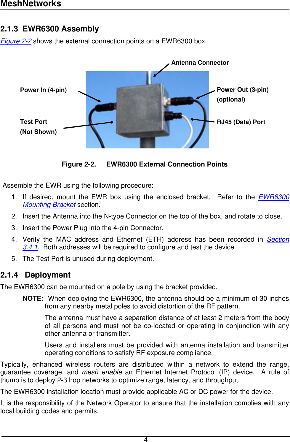
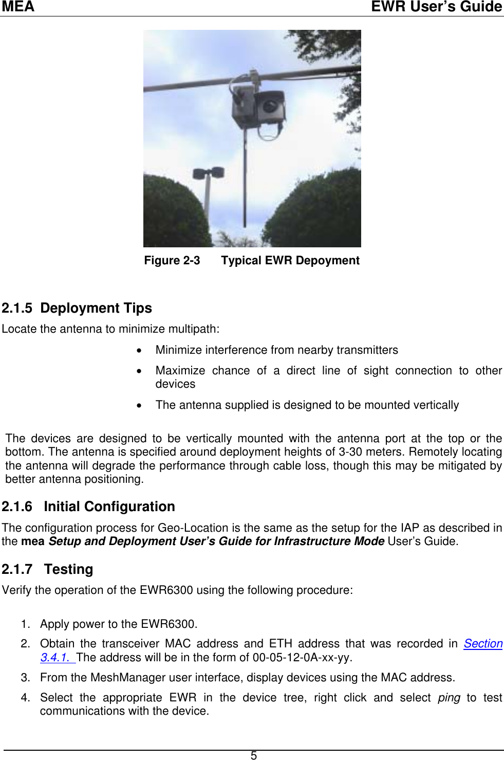
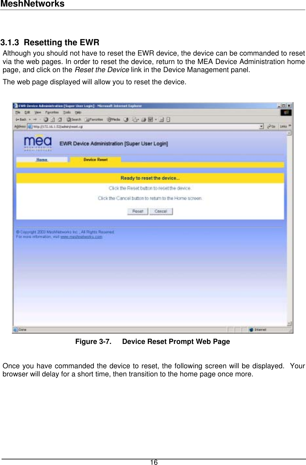
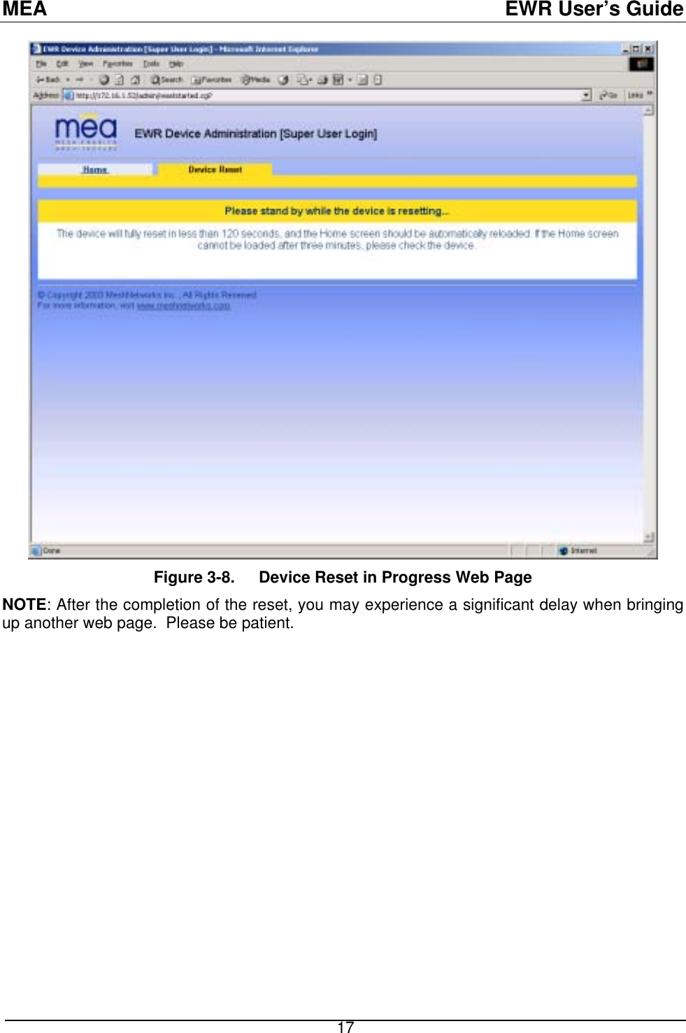
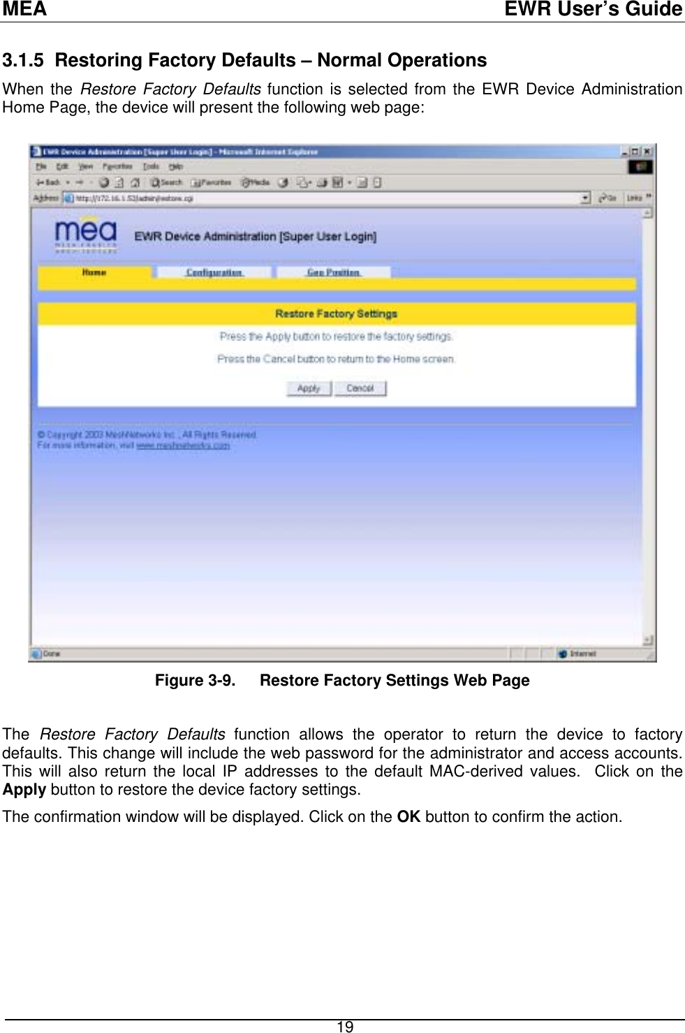
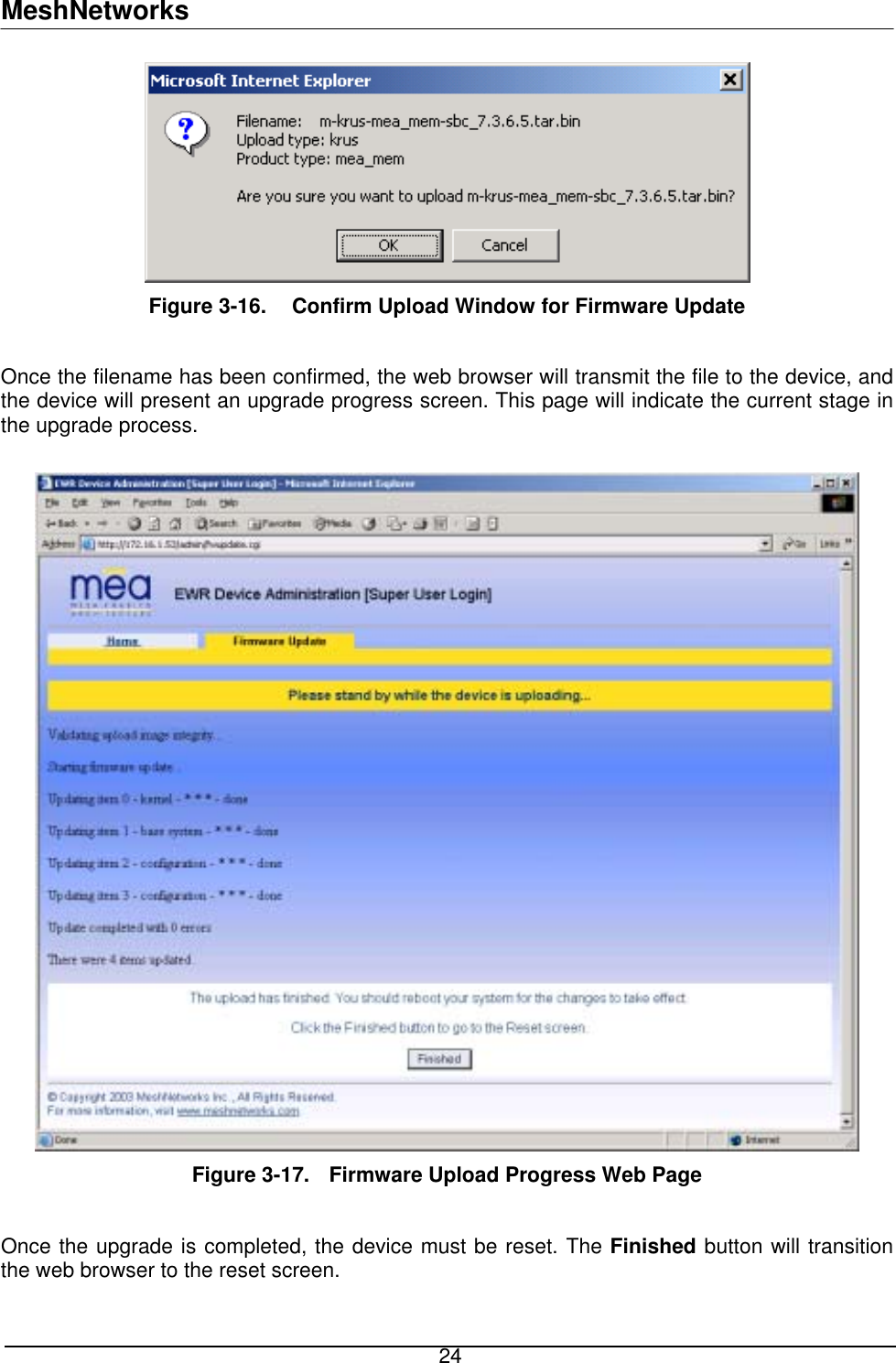
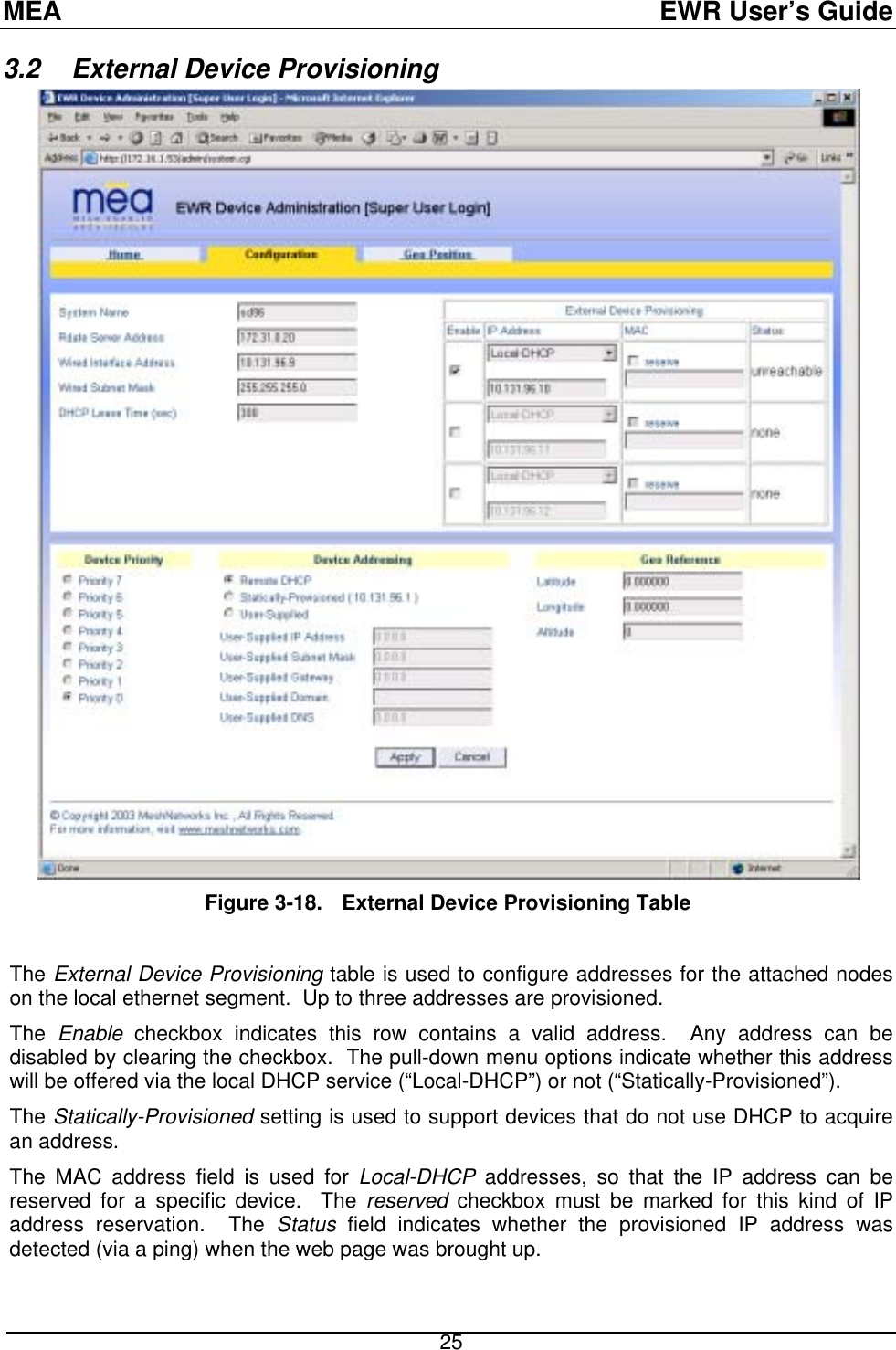
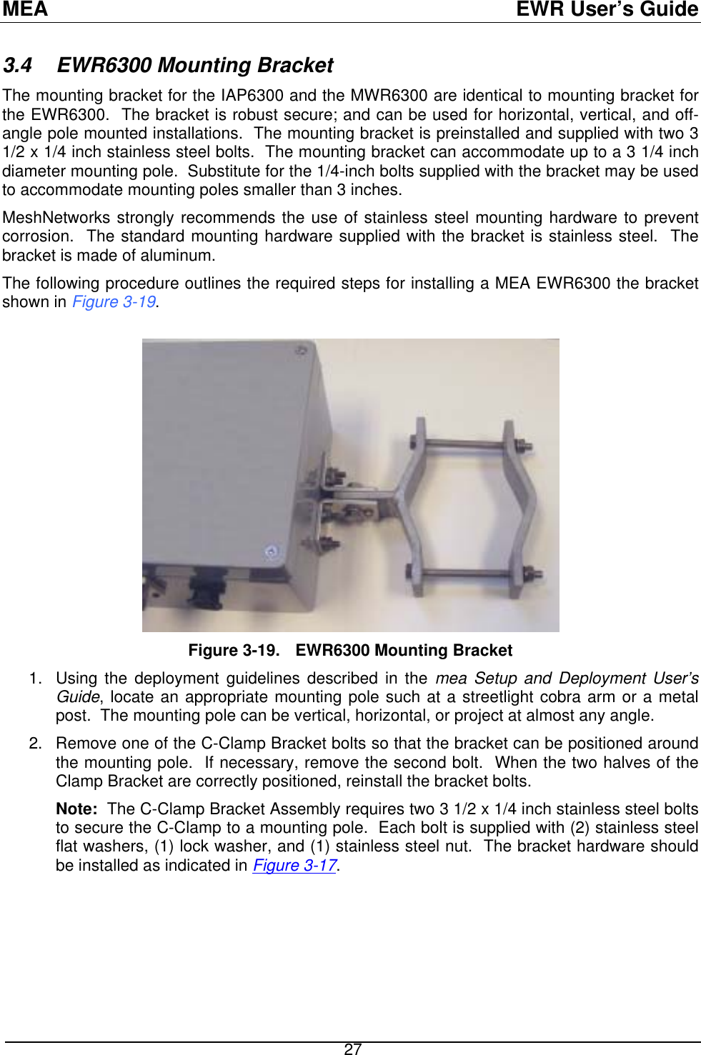
EWR Users Manual
Contents
1.
EWR Users Manual
2.
PWR Users Manual
3.
VMM Users Manual
4.
MEA Setup and Installation Guide
5.
MEA WMC6300 Users Guide for Windows Rel 3
6.
MEA WMC6300 Users Guide Pocket PC rev
7.
Pages from QJEWMC6300704 SA
8.
Pages from QJEWMC6300704 User Manual
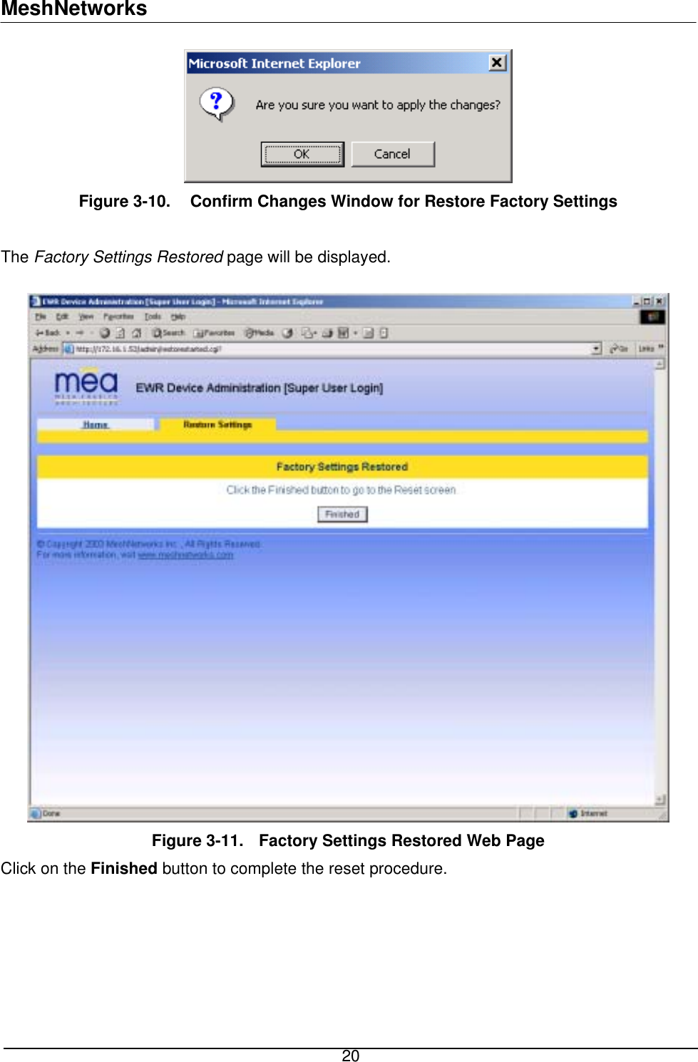
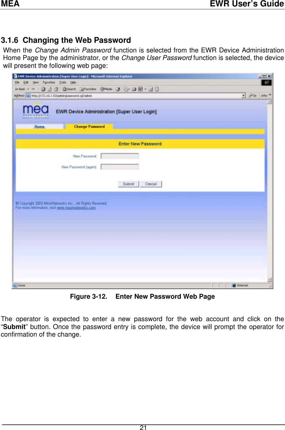
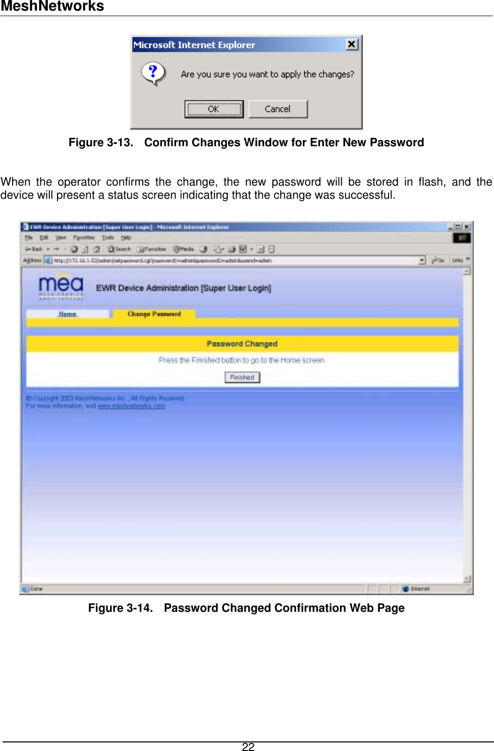
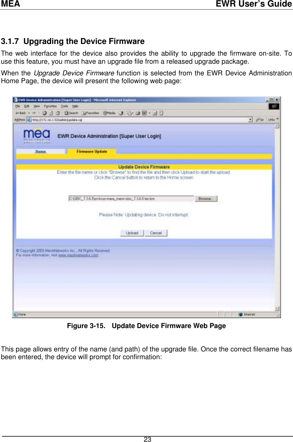
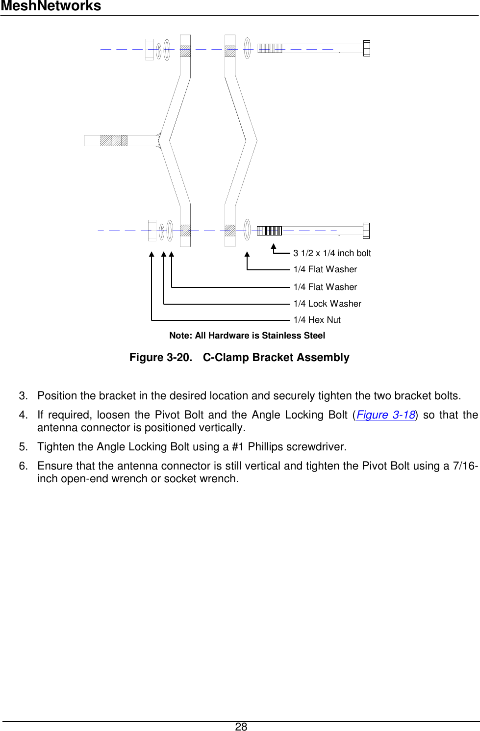
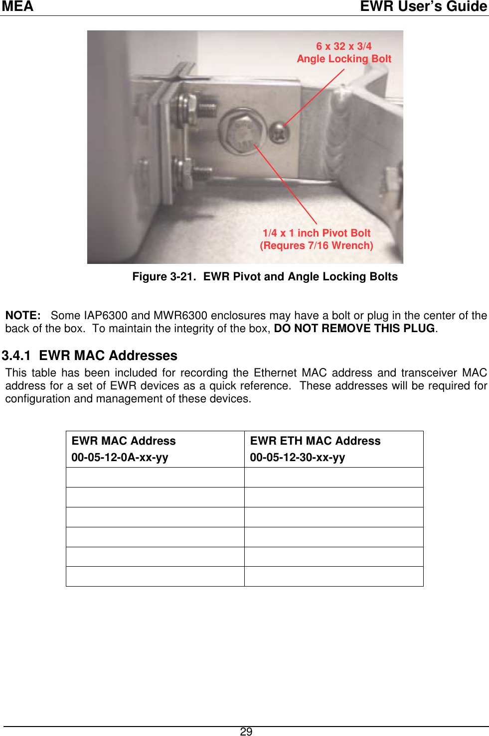
EWR Users Manual
Navigation menu
Upload a User Manual
Namespaces
Wiki Guide
HTML
PDF
Info
Views
User Manual
Discussion / Help
Navigation