Zebra Technologies WTK-5000-00AA WhereTrack User Manual Users guide
Zebra Technologies Corporation WhereTrack Users guide
Users guide

©WhereNet Corp. August 2007D1312r01 WhereTrack Users Guide 28September07.doc Page 1
WhereTrack - WNC
User’s Guide
Document Number D1312r01 Preliminary, August 2007
Model Number: WTK-5000-00AA
WhereNet Corp.
2858 De La Cruz Blvd.
Santa Clara, CA 95050
408-845-8500
WWW.WhereNet.COM

©WhereNet Corp. June 2003 D1312r01 WhereTrack Users Guide 28September07.doc Page 2
FCC Requirements
This device complies with Part 15 of the FCC Rules. Operation is subject to the following two conditions: (1) this
device may not cause harmful interference, and (2) this device must accept any interference received, including
interference that may cause undesired operation.
See FCC registration label, located on the side of the equipment for the FCC, registration.
This equipment has been tested and found to comply with the limits for both Class A and Class B devices, pursuant to Part
15 of the FCC Rules.
Radio Equipment Authorization: FCC ID: NSQWTK-5000
IC: 3586B-WTK5000
This ISM device complies with Canadian ICES-001.
Cet appareil ISM est conforme à la norme NMB-001 du Canada.
Note: IEEE 802.11 functionality will only support b/g (not “a” version).
RF Notice
This device must be installed by professional installers.
The antenna(s) used for this transmitter must be installed to provide a separation distance of at least 20 cm from all
persons and must not be co-located or operating in conjunction with any other antenna or transmitter.
Any changes or modifications to WhereNet Corporation equipment not expressly approved by WhereNet Corporation
could void the user’s authority to operate the equipment.
There are no user-serviceable parts inside. Do not attempt to open the unit for repair.
_
________
_
_
________
_

©WhereNet Corp. June 2003 D1312r01 WhereTrack Users Guide 28September07.doc Page 3
Contents
Introduction ........................................................................................................................4
Installation and Operation ................................................................................................7
WNC Mounting Options....................................................................................................7
Specifications ......................................................................................................................8
©WhereNet Corp. August 2007D1312r01 WhereTrack Users Guide 28September07.doc Page 4
Introduction
System overview
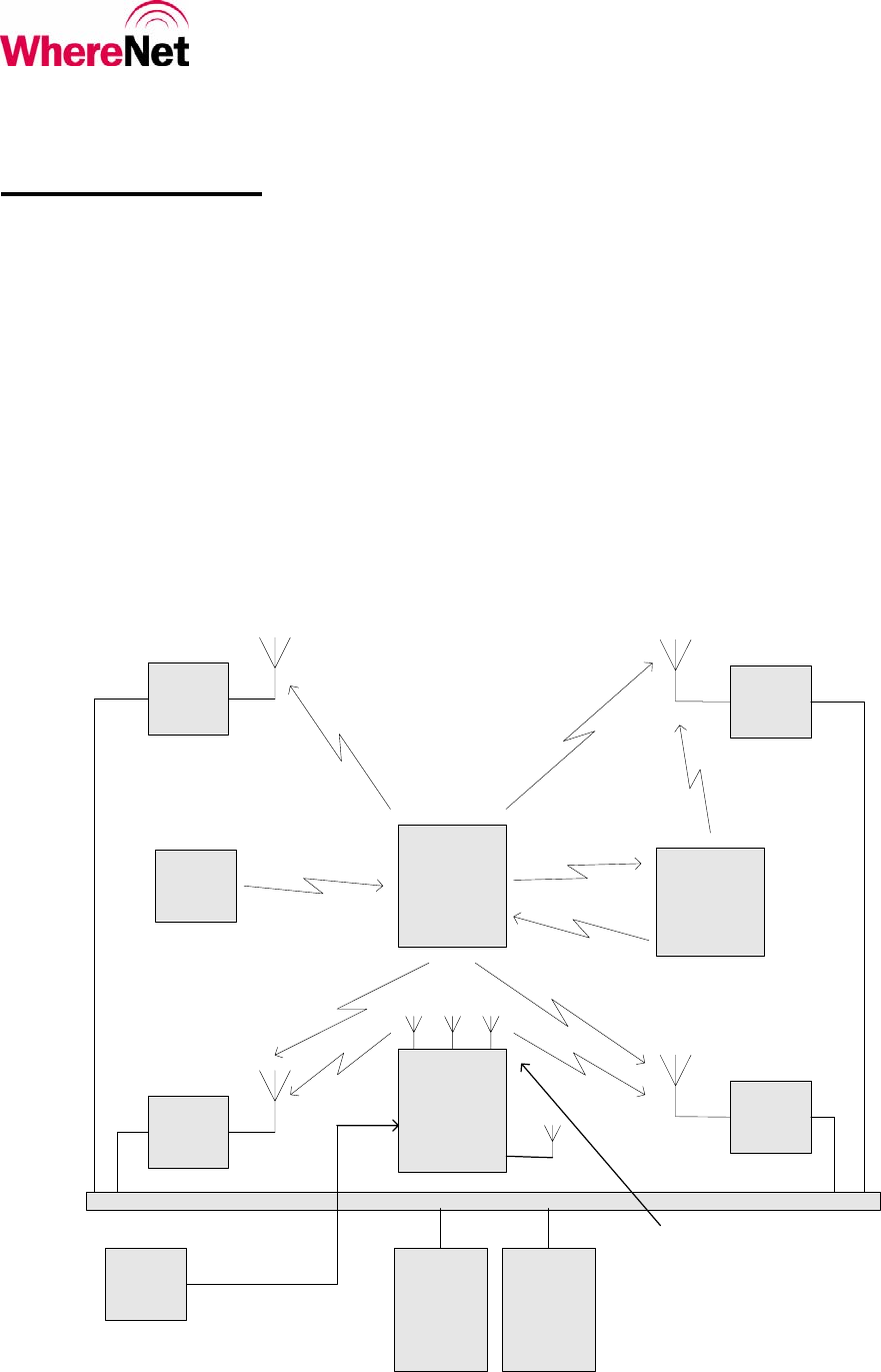
The WhereNet Real Time Locating System (RTLS) is designed to permit users to determine the position of tagged assets
in both indoor and outdoor facilities such as factories and freight yards. The system locates tagged assets by a process
involving redundant triangulation. Each tag autonomously emits a 2.4 GHz direct sequence spread spectrum (DSSS) radio
signal at predetermined blink rate. Each tag’s blink rate is randomized around its predetermined value to minimize the
number of collisions between transmissions made by different tags. The signal emitted by the tag is received by a
minimum of four Location Antennas. A typical transmission contains a preamble which is used to synchronize the
receiver, the tag’s serial number which identifies the tag, a status word which monitors various tag functions, data stored
in the tag’s memory and finally a CRC used to assure that the tag’s message is correct as received.
A WhereTrack or WNC unit may be utilized as part of the RTLS to locate yard vehicles, back haul GPS and telemetry
information from the CPE and also offers WiFi communication capability.
Figure 1: WhereNet Real Time Locating System Block Diagram
WhereTag IV
VSS Server VSS
Database
1-Way 2.4 GHz DSSS or 802.11b
(Range = 1000 ft indoors or 3000 ft
outdoors)
WherePort
III 1-Way 115 kHz FSK
(Range = 25 ft)
WhereWand
Hand-held
Computer with
Laser Barcode
Reader
115 kHz
FSK
2.4 GHz
OOK
(Range = 3 ft)
1-Way
2.4 GHz
DSSS
WhereLan WhereLan
WhereLan
WhereLan
Corporate LAN
Wired
Ethernet or
Wireless
802.11 Link
Wired
Ethernet or
Wireless
802.11 Link
WhereTrack
WNC
1-Way 2.4 GHz DSSS or 2 way
802.11b/g
(Range = 1000 ft outdoors)
GPS
CPE
Ethernet +
DC Power
©WhereNet Corp September 2006D1312r01 WhereTrack Users Guide 28September07.doc Page 5
WhereTrack WNC Unit
The WhereTrack is a custom WhereNet product that supports 802.11b/g WiFi, GPS, and the WhereNet Real Time
Locating System (RTLS). It is a medium sized device that can be attached to a variety of CPE such as UTRs, RTGs,
FELs, STs and SGs. A PACECO PTIU is generally, but not always, also installed on the CPE. If the CPE has a PTIU, the
WNC connects to the PTIU via EtherNet and forwards the PTIU telemetry information to the RTLS through tag
transmissions and provides WiFi back haul connectivity. Some CPEs, such as Quay Cranes, may not require a PTIU, but
may still require a WNC unit. In this case, the WNC provides the function of periodic GPS and RTLS location reporting.
The PTIU is a custom Paceco product that supports a number of digital and analog ports. The PTIU is installed on a
variety of CHE. It’s primary function is to detect the state of sensors, to determine container transition events, and to
report these to the WhereNet MTS SW stack. The PTIU generally connects to sensor signals already available on the
CHE as well as a variety of new sensors installed on the CHE. In some cases, the PTIU also connects to the CHE PLC in
order to obtain the sensor data it requires.
The WNC contains the functionality of 4 internal STHO WhereTags that can be set to "blink" an RF transmission at pre-
programmed rates ranging from 0.5 seconds to one hour between blinks. The WhereNet RTLS infrastructure receives
these blinks and use sophisticated Differential Time of Arrival, (DTOA), algorithms to determine the location of the tag.
Accuracy of this determined location can be as low as 2 meters and is nominally within 3 meters in most installations.
The tag blink data field can also include the GPS locate information as well as other telemetry information that is
connected to the WNC from the CPE. The WNC is also assigned an individual MAC address.

©WhereNet Corp September 2006D1312r01 WhereTrack Users Guide 28September07.doc Page 6
The WhereTrack complies with the ISO 24730-2 RTLS standard and IEEE 802.11b/g standards. It operates in the globally
accepted 2.4GHz frequency band and transmits spread spectrum and WLAN signals in accordance with these standards.
The use of direct sequence spread spectrum technology provides extremely long range; in excess of 1,000 meter locate
range outdoors, and 300 meter locate range indoors.
The WhereTrack device is powered by a 12 to 24V DC input at 12W maximum via a customer supplied input cable (or
cables) which may also supply telemetry or programming information.
Designed to operate in a wide range of outdoor applications, the WNC is fully sealed and rated to IP67 to handle harsh
weather environments. The unit's construction is also resistant to oils, solvents and hydraulic fluids.
WhereLan Location Sensor (LOS) and Location Access Point (LAP)
The Location Sensor and Locating Access Point receive the tag transmissions and forwards the information to the
WhereNet Visibility Server Software which performs locations calculations, database functions and systems management.
The Location Sensors and Locating Access Points communicate with each other and the Visibility Server Software via
standard wired Ethernet cables or an 802.11b-compliant wireless LAN. Utilizing sophisticated DSP technology, the LOS
and LAP are able to track large populations of WhereTags including those from a WhereTrack unit simultaneously. They
can be installed in a grid configuration to provide ubiquitous coverage over large areas comprised of many cells. The
Locating Access Point combines multiple functions: an RTLS Location Sensor and a Wi-Fi certified access point for
wireless LAN clients and applications
Visibility Server Software (VSS)
WhereNet's Visibility Server Software (VSS) is an integrated software package that provides all the tools required to
effectively manage assets and resources as well as the WhereNet Real-Time Locating System (RTLS). Visibility provides
all core software components to allow efficient resource management. Key among those software components is
WhereSoft Locate, which is a distributed Windows Service. When WhereSoft Locate is combined with Visibility and any
of the many applications available from WhereNet, it is possible to locate assets, know their status, and react to any
number of user configurable alert conditions. Visibility also provides the tools required to control and monitor the Real-
Time Location System (RTLS). It includes configuration tools, diagnostics, system alerts, an interface manager and
installation tools.
Laptop Computer
A laptop computer can be used to monitor and configure the WNC settings. This can be accomplished with a serial
connection from a WNC data cable to the computer. A Hyper terminal session can be used to see that the WNC unit
boots correctly and to access the WNC main menu. From the main menu, configuration settings can be set, diagnostic
checks can be made, and internal tag commands can be utilized.
©WhereNet Corp September 2006D1312r01 WhereTrack Users Guide 28September07.doc Page 7
WhereTrack Installation and Operation
WNC units are shipped with all radio emitters deactivated. After installing a WNC to a vehicle to be tracked, the unit must
be activated. This is done using the Ethernet cable serial connection from a computer to the WNC unit along with DC
power. A computer can be used to configure and activate the internal tag functionality, 802.11b/g transceiver, and verify
the GPS receiver function. A WhereNet LAP can be utilized to verify the functionality of the internal tag transmissions
and 802.11b/g communications.
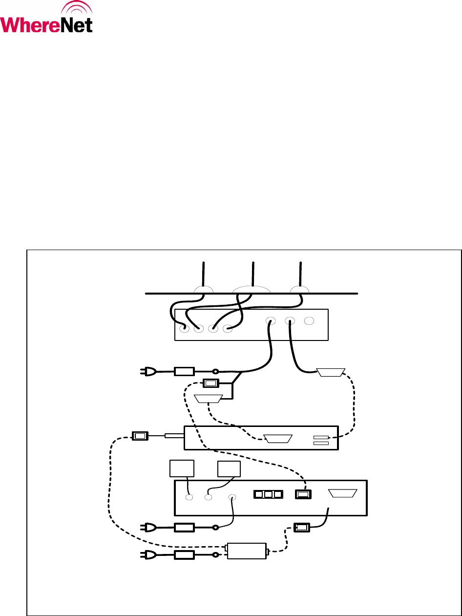
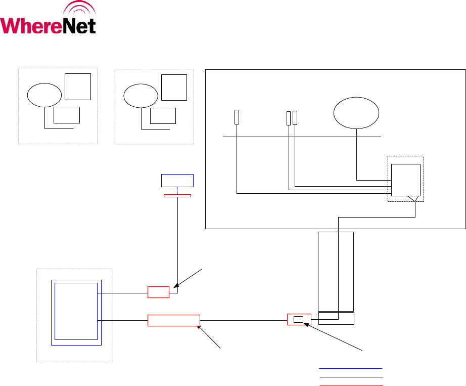
WhereTrack Configuration Diagram
DB-9
RJ-45
Laptop
Computer
USBSerial Port
NIC - PCMCIA
RJ-45
DB-9
LAP
RJ-45
DB-9
RJ-11 x 3
RJ-45
A1 A2 DC
ANT 1 ANT 2
24V DC
24V DC
EN
DC EN + DC
24V DC
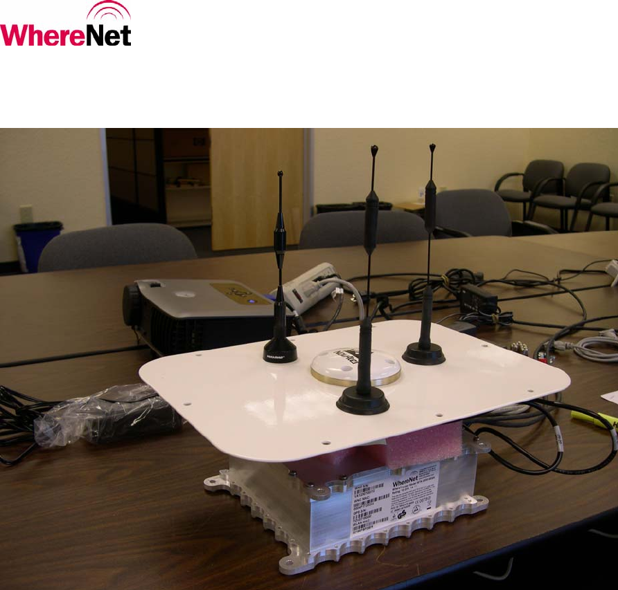
WNC Test Setup
WNC Unit
Antenna Plate
Figure 2
©WhereNet Corp September 2006D1312r01 WhereTrack Users Guide 28September07.doc Page 8
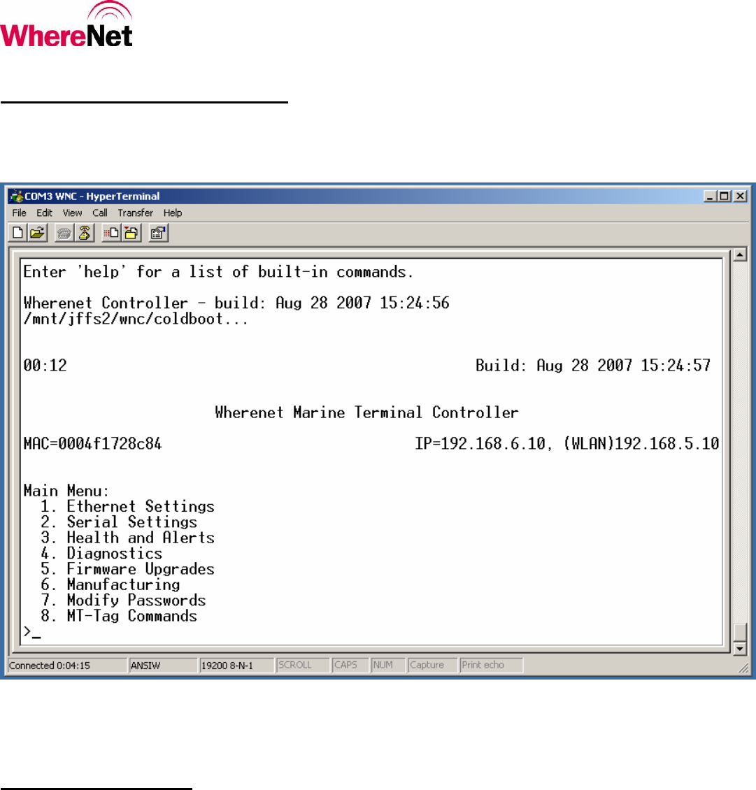
WNC Software Configuration
The WNC unit can be configured by using a hyperterminal window on a laptop computer’s serial connection. Once DC
power is applied to the WNC unit, it executes a software boot sequence which ends at the WNC main menu screen.
From this menu, the WNC can change Ethernet or Serial settings, set health alerts, access diagnostics, upgrade the WNC
firmware, and also control the embedded tag settings.
GPS Master Station
The vast majority of new units will require WhereNet to provide DGPS for the CHE location reporting. This will be
accomplished by the use of a GPS reference receiver or “master station”, whose function is to provide GPS correction
data. The baseline architecture will be inverse DGPS, but the system will be able to support forward DGPS as well.
The GPS Master Station is installed on-site at a location that presents a clear view of the sky for optimum reception of the
GPS satellites. It is envisioned that this will generally be possible by placing the GPS Master Station on the roof-top of a
building in the facility.
©WhereNet Corp September 2006D1312r01 WhereTrack Users Guide 28September07.doc Page 9
PTIU in
NEMA
enclosure
Optional
WP
Whip
antenna
Compass, STHO,
Ultra Sonic senso
r
The GPS Master Station is critical to the operation of the GPS solution. It will consist of a pair of GPS units and will
require the customer to provide DC power derived from redundant DC power supplies whose AC input is backed up by
UPS.
WhereNet has completed preliminary testing of the quality of UTR GPS locates in a Marine Terminal environment.
While not conclusive, the tests indicate that the GPS will be the predominant source of locates over a large area of the
sites, with RTLS locates being used primarily to augment GPS as necessary, such as along the Berth.
WNC CHE Installations
This section highlights how the WhereTrack WNC and PTIU are integrated onto the various CHE.
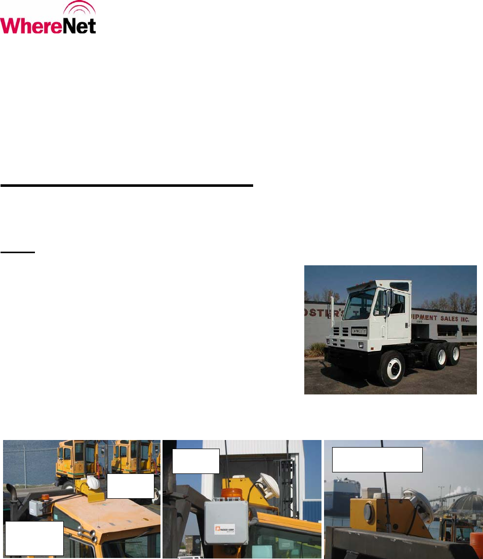
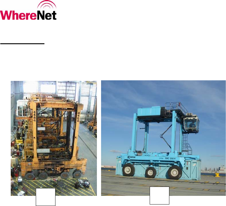
UTR
A UTR is a ‘utility tractor’ or ‘yard truck’ designed to connect or
‘latch’ onto chassis or bomb carts. Container are placed and
removed from these chassis or bomb carts. A sample UTR is
shown in the adjacent photo. Two UTR manufacturers, Capacity
and Ottawa (owned by Kalmar) capture the majority of the US
UTR market. Variations among manufacturers and specific
models exist and their impact on the specific installation of the
WNC, PTIU, and sensors are the responsibility of the customer.
The PTIU is housed inside a NEMA enclosure that is installed on
the back side of the unit. The UTR configuration almost
universally includes the use of so called ‘Top Hat’ that is
installed over the roof of the UTR. The top hat houses an ultra sonic sensor, a compass, an STHO WhereTag with an
external 5’ whip antenna, and an optional WherePort. It is shown in the following photos.
In a new Gen2 installation, a UTR will no longer have a separate STHO WhereTag, as its function will be performed by
the WNC. In addition, PACECO and WhereNet will investigate the use of alternate sensors on the UTR, including the
current ultra sonic sensor and compass. The ultra sonic sensor may be replaced by a different type of sensor, or a different
model of ultra sonic sensor, or it may be kept intact. The compass will be replaced by a similar unit but less expensive
unit.
©WhereNet Corp September 2006D1312r01 WhereTrack Users Guide 28September07.doc Page 10
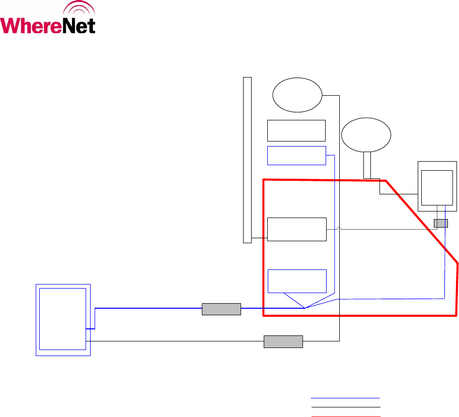
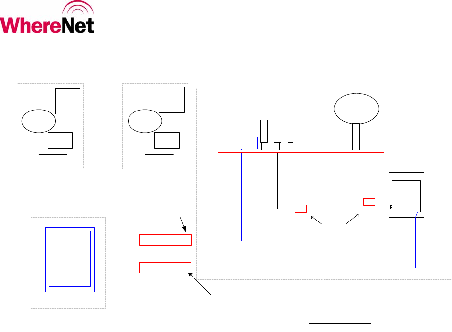
PTIU
PTIU Enclosure
Compass
Container
Presence Sensor
Buddy
HO WT-III
5' Whip Antenna
Bracket
GPS L1
Antenna
GPS Antenna
Mount
Provided by PACECO
Provided by WhereNet
Provided by Customer
WNC Pwr, Gnd, EtherNet Cable
Container Presence Cable
Compass Cable
WNC
5' Whip
Antenna
Flex Conduit
PTIU Enclosure - Top Hat
5' Whip Antenna Cable
GPS
Antenna
Cable WNC
Enclosure
Top Hat
Pwr, Gnd, EtherNet
Flex Conduit for
external WNC
cabling routing, if
any
Note: No cable needed for WNC RS422 debug port. Accessible at UTR roof top.
Optional HD
WP
DC Power
A block diagram of the components and connectivity of the Gen2 hardware is shown below.
Gen2 UTR Installation Block Diagram

©WhereNet Corp September 2006D1312r01 WhereTrack Users Guide 28September07.doc Page 11
Conduit run
for Gen1
STHO
WP on RTG
leg, truck lane
Two RTGs
WiFi
installatio
n on RTG
RTG/Transtainer
An RTG is a large CHE that can create large container stacks and deliver and receive container to and from UTRs and
over-the-road trucks. RTGs vary from 50’ to 100’ in overall height, depending upon the make/model. Sample RTGs are
shown in the following photos.
Variations among RTG manufacturers and specific models exist
and their impact on the specific installation of the WNC, PTIU, and
sensors are the responsibility of the customer.
The PTIU is housed inside a NEMA enclosure that is usually
installed in the equipment room of the RTG. The PTIU generally
connects to the RTG PLC in order to obtain the necessary telemetry
data. In some cases, PACECO has installed sensors in lieu of the
PLC interface. The Gen1 WhereNet products on an RTG are: one
STHO WhereTag, one buddy WTIII, two hardened WPs, two
rugged WP mounts, and two WP health tags. In a Gen2
configuration, the STHO WhereTag is deleted and a WNC is added.
In addition, a compass is also added if the site has no RTLS
coverage along RTG runs.
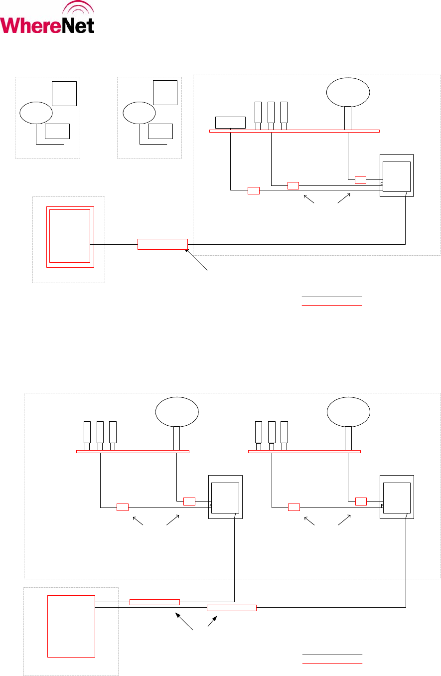
A block diagram of the components and connectivity of the Gen2 hardware is shown below.
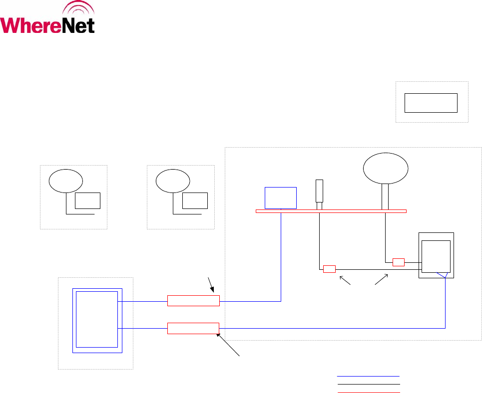
©WhereNet Corp September 2006D1312r01 WhereTrack Users Guide 28September07.doc Page 12
PTIU
PTIU Enclosure
Optional
Compass
Buddy
HO WT-III
GPS L1
Antenna
GPS Antenna Mount
Provided by PACECO
Provided by WhereNet
Provided by Customer
WNC Pwr, Gnd, EtherNet Cable
WNC Debug port cable
WNC
Flex Counduit
PTIU Enclosure - WNC Enclosure
GPS
Antenna
Cable
WNC
Enclosure
RTG Equipment Room
(variations exist)
Top of RTG over Truck Lane
Site Variations per RTG model
Top of RTG over Container Bay
Site Variations per RTG model
RTLS/WiFi
Antenna
RTLS/WiFi
Antenna Mount
RTLS/WiFi
Antenna Cable
Note 1
Note 1: CFE antenna attachment ( brackets, unistruts, etc) neeeded to elevate antennas above metallic obstructions at the top of RTG
Pwr, Gnd, EtherNet, Debug port RS422
Flex Counduit
Antenna - WNC Enclosure
Compass RS422 cable
Flex Counduit
PTIU Enclosure - Compass
HD WPIII
Health
WTIII
HD WP Bracket
HD WPIII
Health
WTIII
HD WP Bracket
Right RTG Truck Lane Leg Left RTG Truck Lane Leg
Note 2: PTIU-RTG PLC EtherNet connection via WNC not recommended. Use hub in equipment room.
Gen2 RTG Installation Block
Diagram
©WhereNet Corp September 2006D1312r01 WhereTrack Users Guide 28September07.doc Page 13
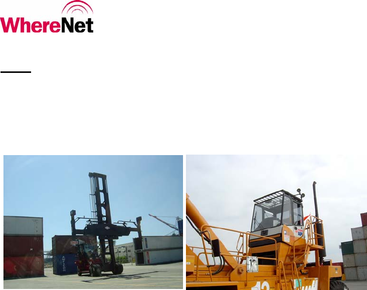
FEL
A FEL is a large CHE that can create large container stacks and deliver and receive container to and from UTRs and over-
the-road trucks. FELs vary greatly in design, depending upon the make/model. Some FELs are designed to pick up
empty containers (‘Side Handlers’), and some are designed to pick up loaded containers (“Top Handlers”). Sample FELs
are limited to stacks of containers up to 5-high, whereas others can work with 6-high and 7-high container stacks. Sample
FELs are shown below.
Variations among FEL manufacturers and specific models exist and their impact on the specific installation of the WNC,
PTIU, and sensors are the responsibility of the customer.
The PTIU is housed inside a NEMA enclosure that is usually installed in the space underneath the FEL operator’s cab. To
date, the PTIU generally does not connect to the FEL (Top Handler) PLC in order to obtain the necessary telemetry data.
Generally, the PTIU ‘taps’ onto existing sensor or new sensors are installed in lieu of a direct PLC interface. The Gen1
WhereNet products on an FEL are: one WhereMast and mount, one WhereDome with cabling, two hardened WPs, two
rugged WP mounts, and two WP health tags. In a Gen2 configuration, the individual STHOs housed inside the
WhereDome obsoleted. The WhereDome instead houses the WNC, GPS antenna, and RTLS/WiFi antennas. It is
anticipated that the WNC will be housed in an enclosure different from the use used one UTRs/RTGs/etc due to the
specific constraints of the WhereMast/WhereDome dimensions.
In the Gen1 solution, the WhereDome also houses the digital compass, which is provided by PACECO. For the Gen2
solution, PACECO and WhereNet will determine whether the compass can instead be installed elsewhere on the FEL,
such as on the rooftop of the operator’s cab.
A block diagram of the components and connectivity of the Gen2 hardware is shown below. For planning purposes, the
FEL compass is shown as being installed outside the WhereDome/WhereMast.
©WhereNet Corp September 2006D1312r01 WhereTrack Users Guide 28September07.doc Page 14
PTIU
PTIU Enclosure
Compass
GPS L1
Antenna
Provided by PACECO
Provided by WhereNet
Provided by Customer
WNC Pwr, Gnd, EtherNet Cable
WNC Debug port cable
WNC
Flex Counduit
PTIU Enclosure - WhereMast Base
GPS
Antenna
Cable
WNC
WhereDome
Enclosure
Underneath Operator's Cab
WhereDome
WhereDome
RTLS Antennas
Antenna Cables
Note 1: Compass may be mounted on roof top of FEL cab pending performance test results.
Note 1
Pwr, Gnd, EtherNet,
Debug port RS422
Compass RS422 cable
Flex Counduit
PTIU Enclosure - Compass
HD WPIII
Health
WTIII
HD WP Bracket
Right Spreader End Left Spreader End
Opt.
Health
WTIII HD WPIII
Health
WTIII
HD WP Bracket
Opt.
Health
WTIII
Shared
WiFi/RTLS
WhereDome
Antenna
Ground Plane Plate
WhereMast
WhereMast Mount Kit
Junction Box
Spec pigtail cross-connect
Gen2 FEL Installation Block Diagram
©WhereNet Corp September 2006D1312r01 WhereTrack Users Guide 28September07.doc Page 15
SC and ST
SCs and STs are CHE used by so called ‘straddle’ operators. Straddle container stacks are different than FEL/RTG stacks
in that containers are not placed immediately adjacent to one another. They are stacked from 2-high or 3-high creating
long rows of containers separated from each other by about 7’. An SC and an ST are shown in the following photo.
Neither WhereNet nor PACECO have installed any equipment (yet) on an SC/ST. The installation, however, is expected
to be straightforward. The PTIU and WNC will be installed at the top of the SC/ST. It will most likely be necessary to
raise the WNC’s GPS antenna, WiFi/RTLS antennas, and compass relative to the possible point of installation of the
WNC enclosure. As in the case of the RTG, the necessary brackets to do this will be the responsibility of the customer.
A block diagram of the components and connectivity of the Gen2 hardware is shown below.
SC ST
©WhereNet Corp September 2006D1312r01 WhereTrack Users Guide 28September07.doc Page 16
PTIU
PTIU Enclosure
Compass
GPS L1
Antenna
GPS Antenna Mount
Provided by PACECO
Provided by WhereNet
Provided by Customer
WNC Pwr, Gnd, EtherNet Cable
WNC
Flex Counduit
PTIU Enclosure - WNC Enclosure
GPS
Antenna
Cable
WNC
Enclosure
Top of SC/ST
Mounting variations possible per CHE model
RTLS/WiFi
Antennas
RTLS/WiFi
Antenna Mounts
RTLS/WiFi
Antenna Cables
Note 1
Note 1: CFE antenna attachment ( brackets, unistruts, etc) neeeded to elevate antennas above metallic obstructions at the top of CHE
Note 2: CFE compass attachment (flat surface!) needed at TBD compass mounting location at top of CHE.
Pwr, Gnd, EtherNet
Flex Counduit
Antenna - WNC Enclosure
Compass RS422 cable
Flex Counduit
PTIU Enclosure - Compass
HD WPIII
Health
WTIII
HD WP Bracket
HD WPIII
Health
WTIII
HD WP Bracket
Right SC/ST Truck Lane Leg Left SC/ST Truck Lane Leg
Note 3: PTIU-RTG EtherNet connection via WNCmakes viable. CHE PLC is housed in vehicle cab near top of CHE.
WP on Legs Optional
Solution Dependant
Top of SC/ST
Mounting variations possible per CHE model
Opt.
Health
WTIII
Opt.
Health
WTIII
Gen2 SC/ST Installation Block Diagram, PTIU
WhereNet is currently looking to establish an OEM or partnership agreements with one or more CHE manufacturers.
These discussions are at their earliest stages. However, it is anticipated that it may be possible to connect the WNC
directly to the SC/ST PLC, instead of the PTIU. For planning purposes, the following block diagram shows the
corresponding components and connectivity. It should be noted that, in this configuration, the WNC will likely need to
interface to a compass.
©WhereNet Corp September 2006D1312r01 WhereTrack Users Guide 28September07.doc Page 17
Network Drop Point
UPS AC, Redundant DC P/Ss
GPS L1
Antenna
GPS Antenna Mount
Provided by WhereNet
Provided by Customer
WNC
Flex Counduit
RootTop Access - WNC Enclosure
GPS
Antenna
Cable
WNC
Enclosure
Note 1
Note 1: CFE antenna attachment ( brackets, unistruts, etc) neeeded to elevate antennas above metallic obstructions at installation point.
Pwr, EtherNet, Gnd
Flex Counduit
Antenna - WNC Enclosure
On-Site Building Roof Top (or equivalent)
RTLS/WiFi
Antennas
RTLS/WiFi
Antenna Mounts
RTLS/WiFi
Antenna Cables
GPS L1
Antenna
GPS Antenna Mount
WNC
GPS
Antenna
Cable
WNC
Enclosure
Note 1
Pwr, EtherNet, Gnd
Flex Counduit
Antenna - WNC Enclosure
RTLS/WiFi
Antenna Mounts
RTLS/WiFi
Antenna Cables
PLC
PLC Cover
Compass
GPS L1
Antenna
GPS Antenna Mount
Provided by WhereNet
Provided by Customer
WNC Pwr, Gnd, EtherNet Cable
or RS232/422 cabling
WNC
Flex Counduit
PTIU Enclosure - WNC Enclosure
GPS
Antenna
Cable
WNC
Enclosure
Top of CHE (usually inside operator's cab)
Note 1
Note 1: CFE antenna attachment ( brackets, unistruts, etc) neeeded to elevate antennas above metallic obstructions at the top of CHE
Note 2: CFE compass attachment (flat surface!) needed at TBD compass mounting location at top of CHE.
Pwr, Gnd, EtherNet or RS/232/422 cable
Flex Counduit
Antenna - WNC Enclosure
Note 3: WhereNet is attempting to establish OEM relationships with various CHE manufacturers. The plan would be to connect directly to the CHE PLC.
The connection details are NOT known. It is expected that the connection would be RS232/422 serial or over EtherNet. Protocol/messaging is 100% TBD.
Top of CHE
Mounting variations possible per CHE model
RTLS/WiFi
Antennas
RTLS/WiFi
Antenna Mounts
RTLS/WiFi
Antenna Cables
HD WPIII
Health
WTIII
HD WP Bracket
HD WPIII
Health
WTIII
HD WP Bracket
Right SC/ST Truck Lane Leg Left SC/ST Truck Lane Leg
WP on Legs Optional
Solution Dependant
Opt.
Health
WTIII
Opt.
Health
WTIII
Gen2 SC/ST Installation Block Diagram, PLC Connect
GPS Master Station
The following diagram shows the components and connectivity of the Master Station installation.
Gen2 GPS Master Station Installation Block Diagram
©WhereNet Corp September 2006D1312r01 WhereTrack Users Guide 28September07.doc Page 18
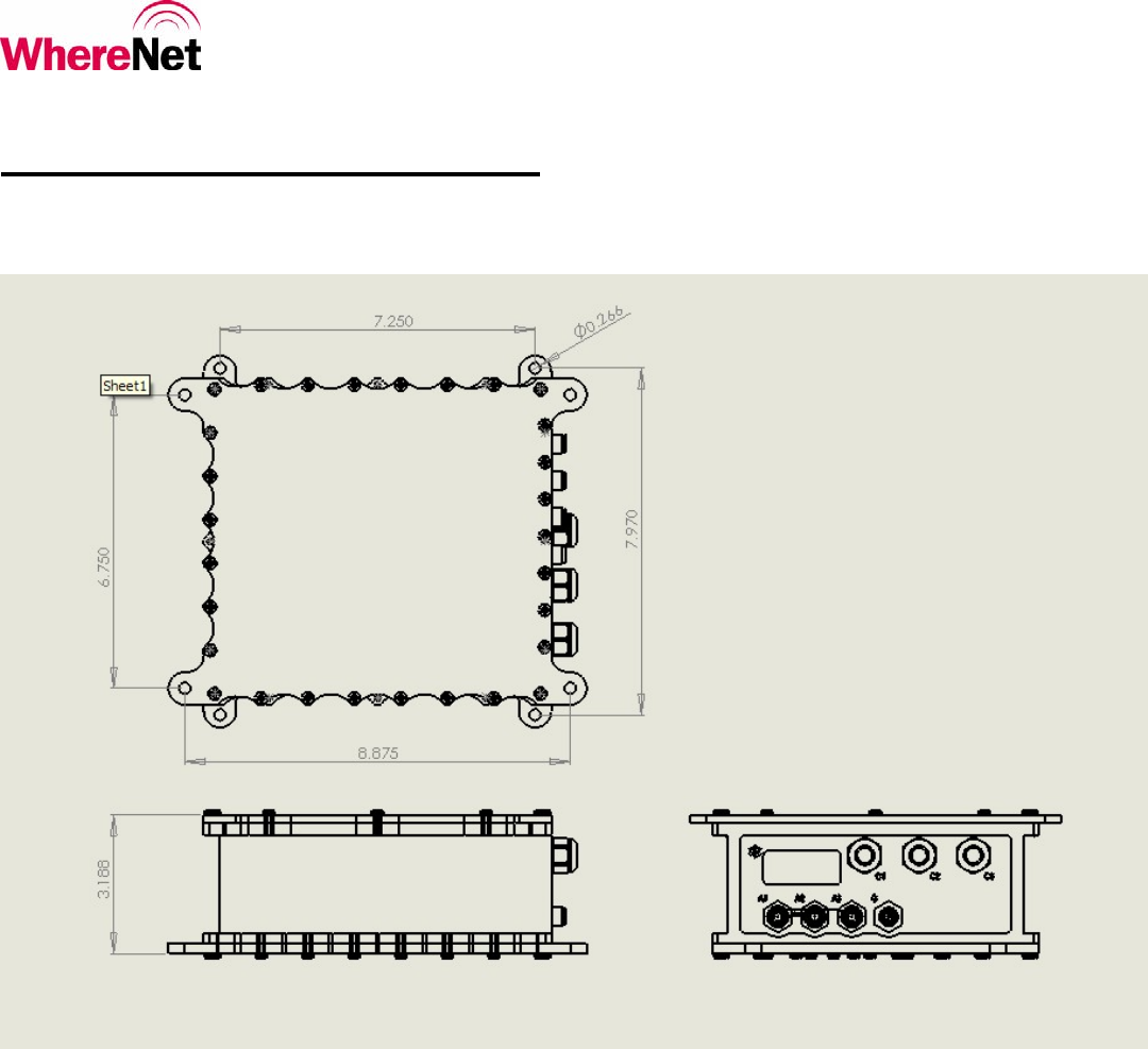
WNC Mounting Options
The mounting of the WNC unit will depend on the specific application for the WNC. Please refer to the installation instructions for
each particular application for specific instructions. Below is an outline drawing of the WNC that details the mounting hole locations.

©WhereNet Corp September 2006D1312r01 WhereTrack Users Guide 28September07.doc Page 19
Specifications (Subject to change without notice)
WhereTrack (Model #: WTK-5000-00AA)
CAPABILITIES
Frequency Range .......................................... 2.4 to 2.4835 GHz
Typical Locate/Data Range........................... 1,000 m (3200 ft)
Typical 802.11b/g Range.............................. 1,000 m (3200 ft)
User Configurable Blink Rate....................... 0.5 sec to 5 days
GPS Locate Accuracy..……………………. TBD
WNC MOUNTING OPTONS
Mounting method varies depending on application
- FEL mounting plate
- Top Hat box
ELECTRICAL
Power............................................................ 12V to 24V DC at 1A max.
Data Input……………………………………EtherNet (CAT-5): RS232, RS485, 10/100BT
ENVIRONMENTAL / PHYSICAL
Operating Temperature Range...................... -40º C to +60º C (-40º F to +140º F)
Storage Temperature Range.......................... -40º C to +85º C (-40º F to +185º F)
Durability...................................................... TBD drop to concrete
Height, without antenna plate ....................... 8.2 cm (3.2 in)
Length, including mounting tabs .................. 24.2 cm (9.5 in)
Width, including mounting tabs.................... 21.6 cm (8.5 in)
Weight........................................................... TBD
Environmental Sealing.................................. IP67 (dust tight, immersible)
Case Material................................................ Aluminum Housing
REGULATORY APPROVALS
FCC Part 15 Class B
FCC Part 15.247
IC RS210
Electrical Safety IEC/EN 60950-1
EN 300328
EN301489-1/-17