Zentri B5BD9 Numbat User Manual Heading 1
ACKme Networks Inc Numbat Heading 1
UserManual.wiki
>
Zentri
>
B5BD9 User Manual
Users Manual
Navigation menu
Upload a User Manual
Namespaces
Wiki Guide
HTML
PDF
Info
Views
User Manual
Discussion / Help
Navigation
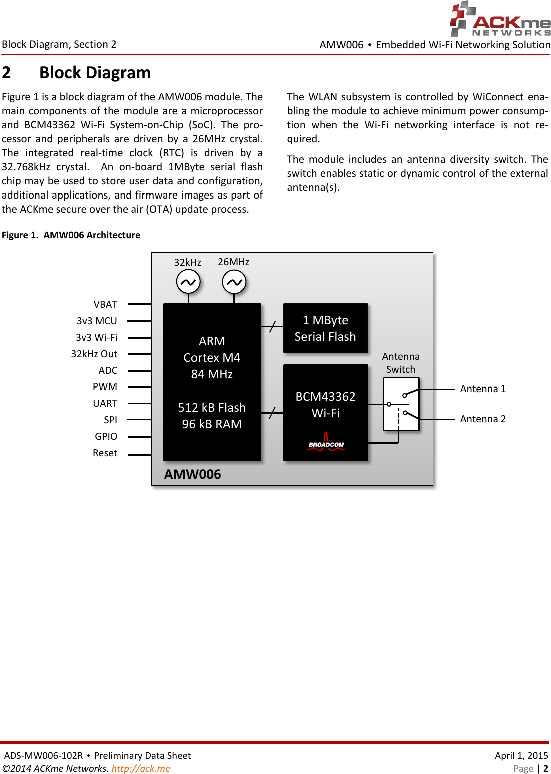
![AMW006 • Embedded Wi-Fi Networking Solution Regulatory Certification, Section 7 ADS-MW006-102R • Preliminary Data Sheet April 1, 2015 ©2014 ACKme Networks. http://ack.me Page | 17 Labeling and User Information Requirements The label on the final product which contains the AMW006 module must follow CE marking require-ments. The R&TTE Compliance Association Technical Guidance Note 01 provides guidance on final product CE marking External Antenna Requirements From R&TTE Compliance Association document Tech-nical Guidance Note 01: Provided the integrator installing an assessed radio module with an integral or specific antenna and in-stalled in conformance with the radio module manufac-turer’s installation instructions requires no further evaluation under Article 3.2 of the R&TTE Directive and does not require further involvement of an R&TTE Di-rective Notified Body for the final product. [Section 2.2.4] The European Compliance Testing listed in Table 12. European Compliance Testing was performed using an-tenna types listed in Table 11 - Tested External Antenna Types. Further Information A document that can be used as a starting point in un-derstanding the use of Short Range Devices (SRD) in Europe is the European Radio Communications Com-mittee (ERC) Recommendation 70-03 E, which can be downloaded from the European Radio Communications Office (ERO) at: http://www.ero.dk. Further information may be obtained from the follow-ing websites: Radio and Telecommunications Terminal Equip-ment (R&TTE) http://ec.europa.eu/enterprise/rtte/index_en.htm European Conference of Postal and Telecommuni-cations Administrations (CEPT) http://www.cept.org European Telecommunications Standards Institute (ETSI) http://www.etsi.org European Radio Communications Office (ERO) http://www.ero.dk The Radio and Telecommunications Terminal Equipment Compliance Association (R&TTE CA) http://www.rtteca.com/ NOTE: To maintain conformance to the testing listed in Table 12. European Compliance Testing, the module shall be installed in accordance with the installation instructions in this data sheet and shall not be modified. When integrating a radio module into a completed product the integrator becomes the manufacturer of the final product and is therefore responsible for demonstrating compliance of the final product with the essential requirements of the R&TTE Directive.](https://usermanual.wiki/Zentri/B5BD9/User-Guide-2581862-Page-21.png)