Zero One Technology Co WP02001 Wireless Print Server User Manual Manual
Zero One Technology Co Ltd Wireless Print Server Manual
UserManual.wiki
>
Zero One Technology Co
>
WP02001 User Manual
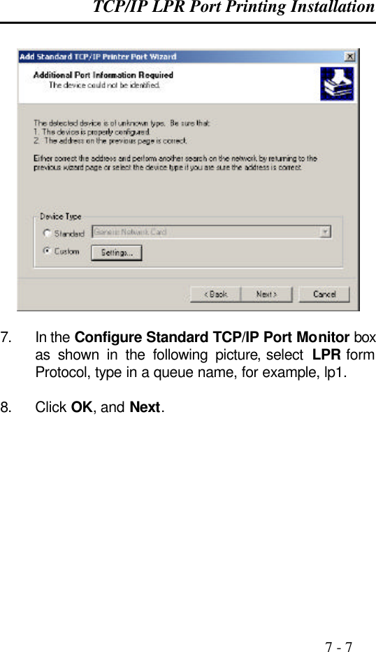
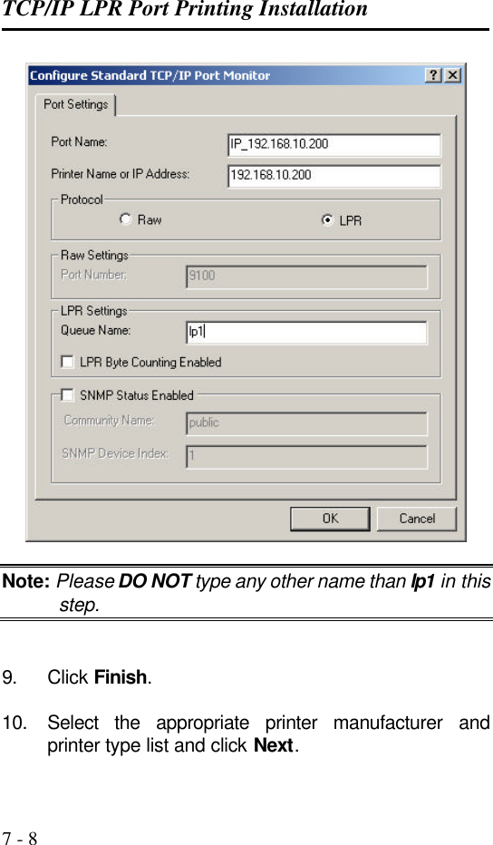
Manual
Navigation menu
Upload a User Manual
Namespaces
Wiki Guide
HTML
PDF
Info
Views
User Manual
Discussion / Help
Navigation
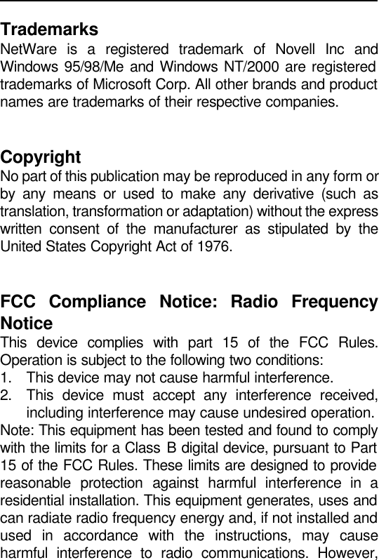
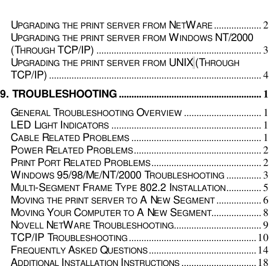
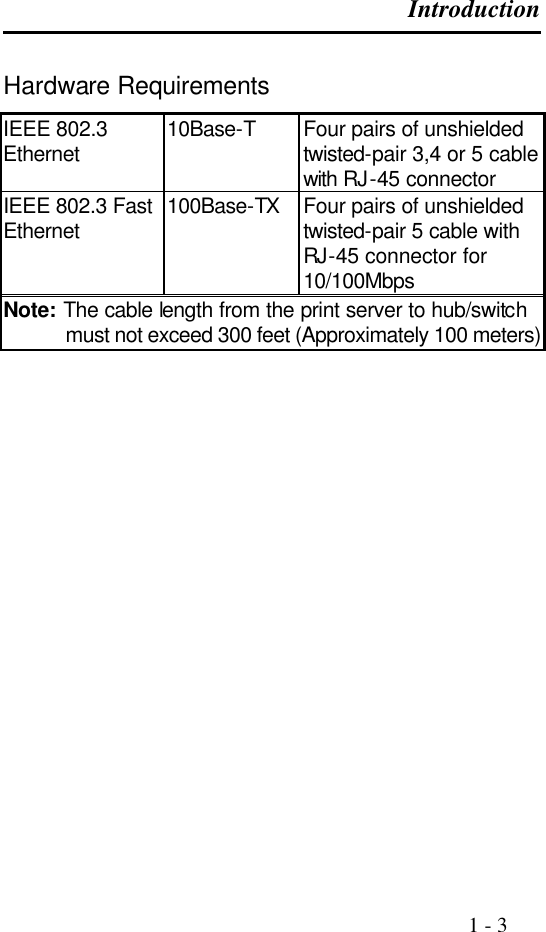
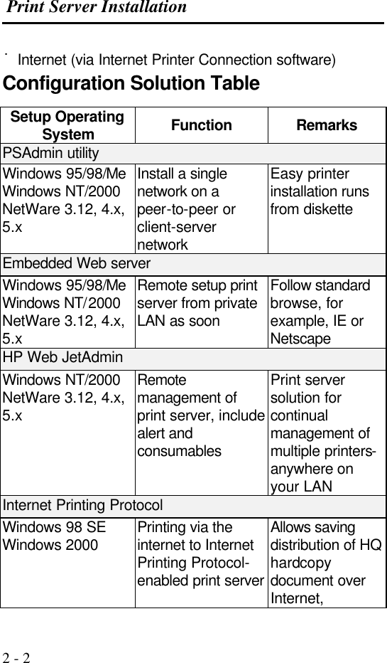
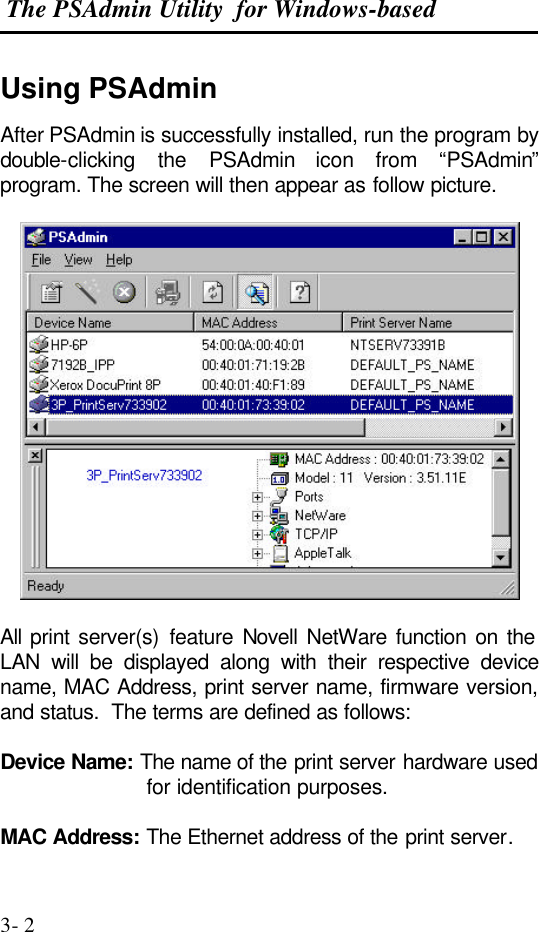
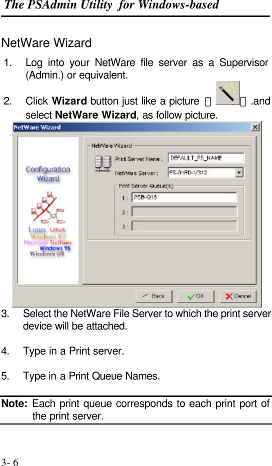
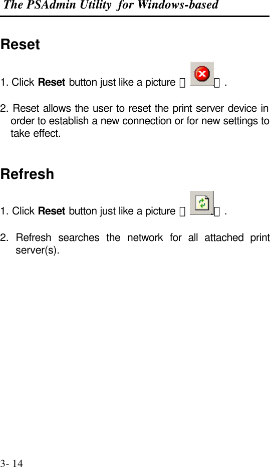
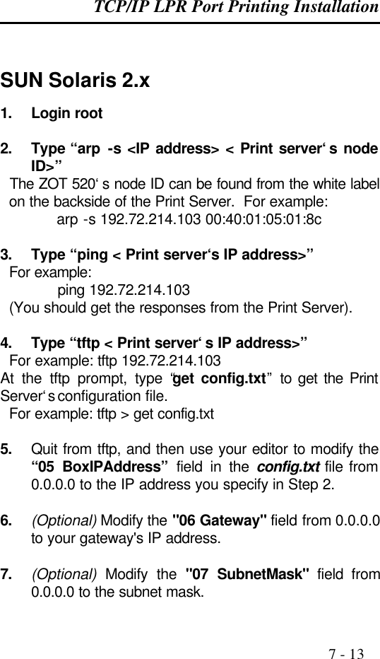
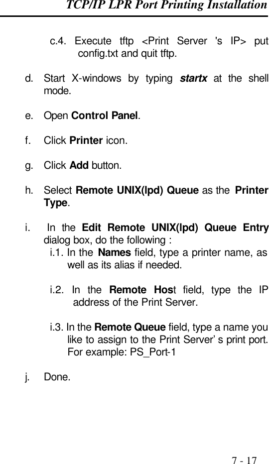
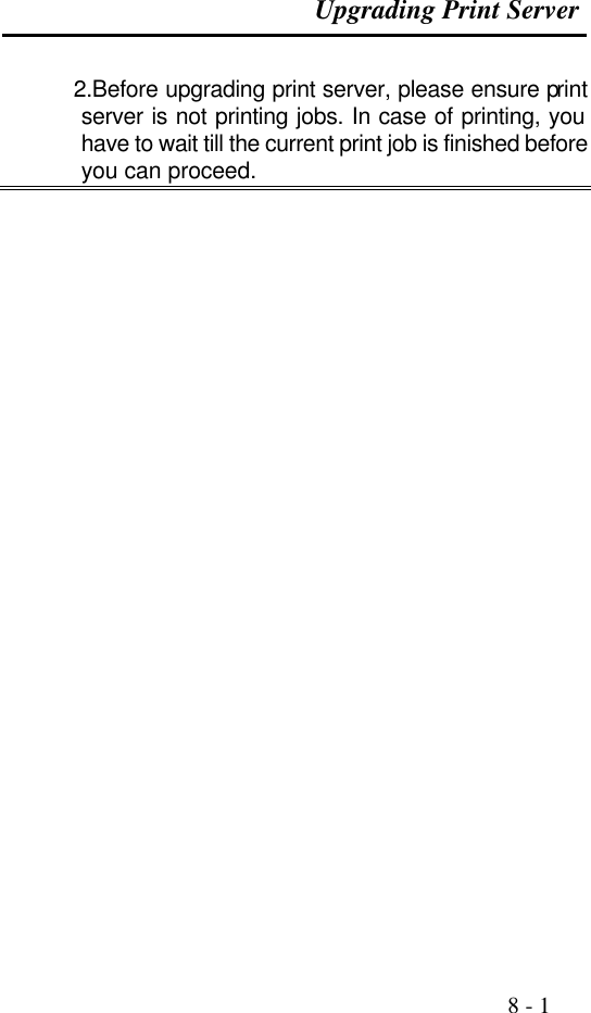
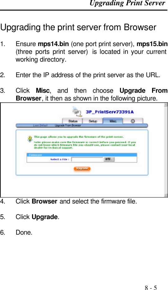
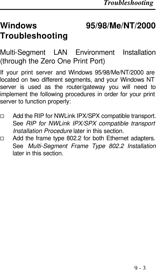
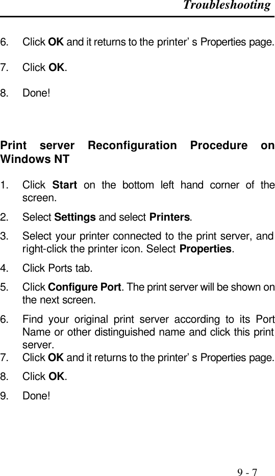
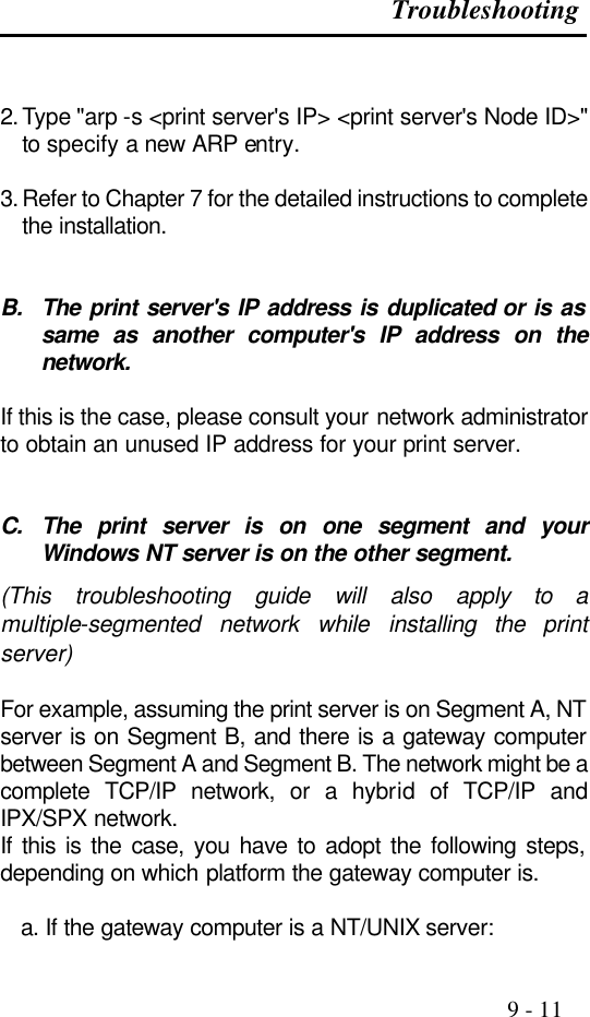
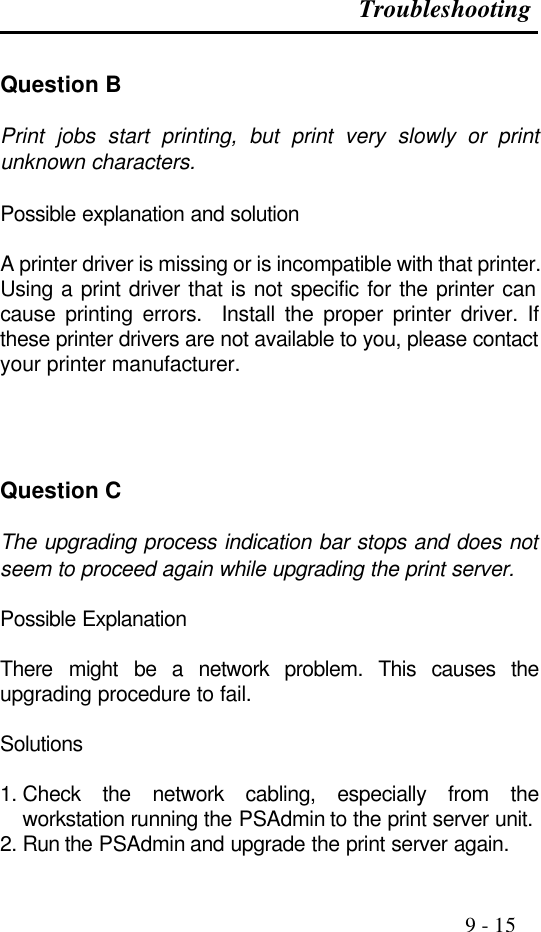
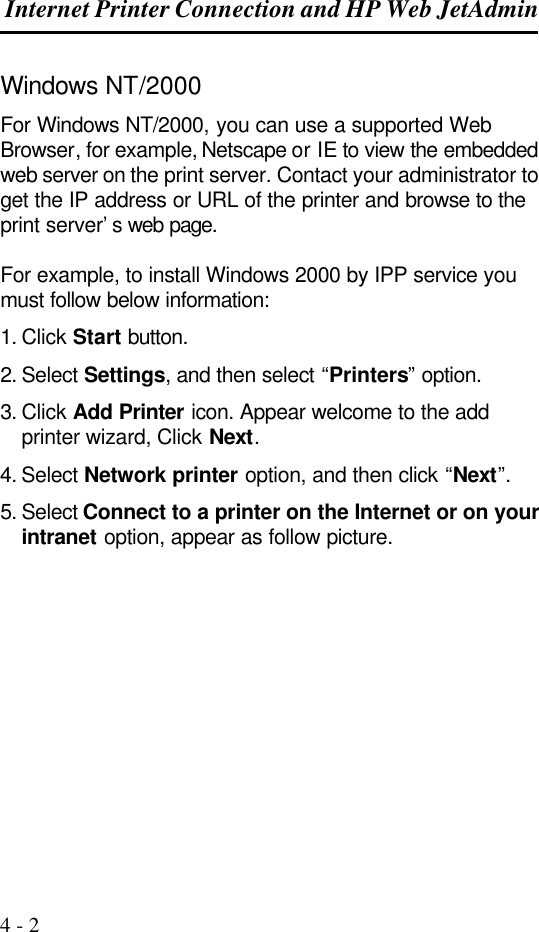
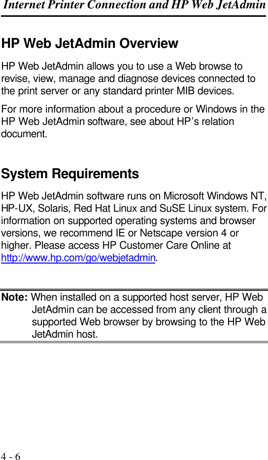
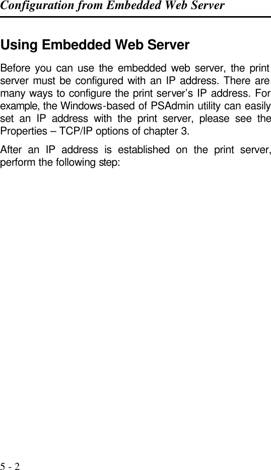
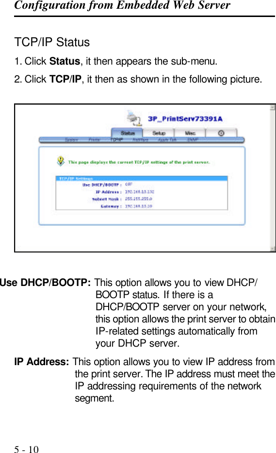
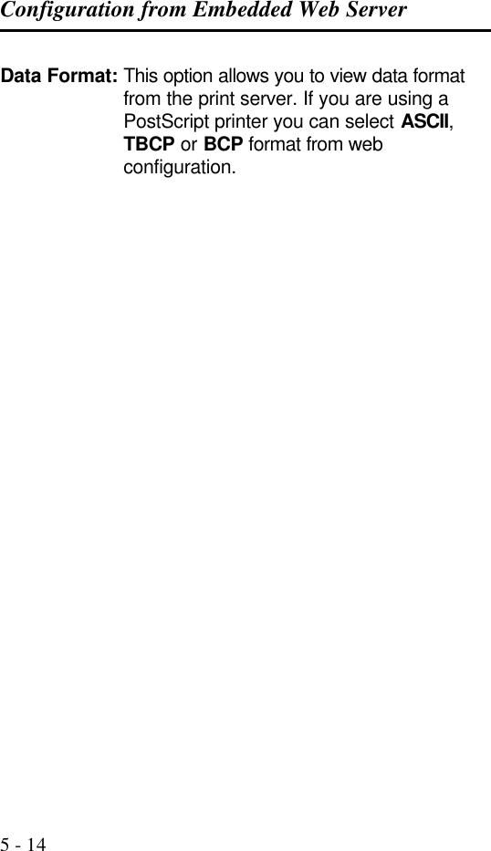
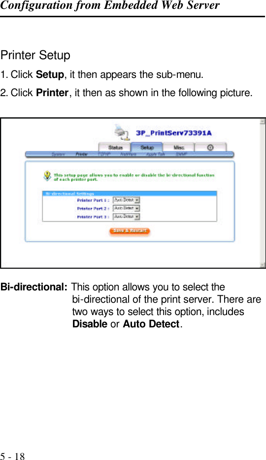
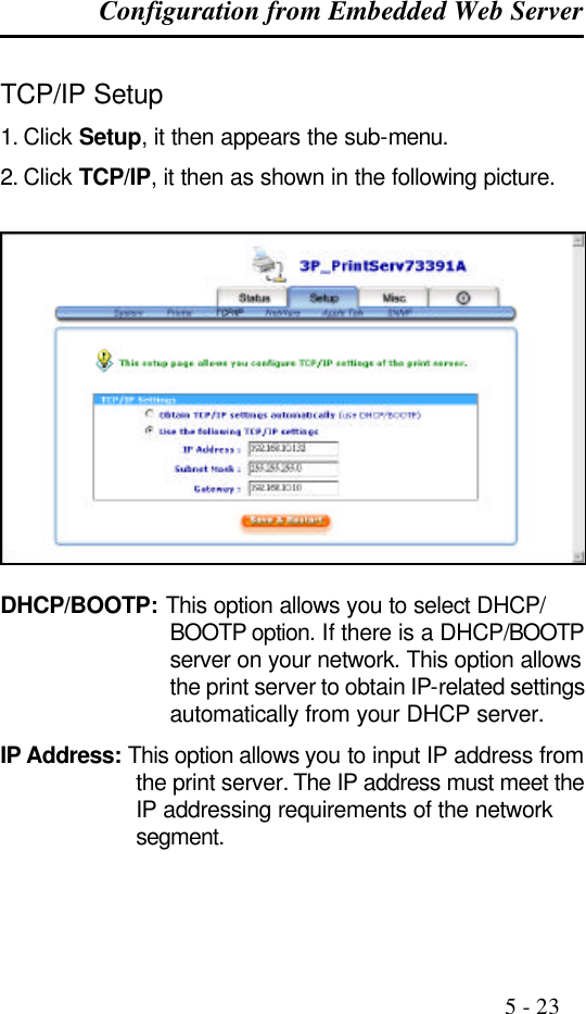
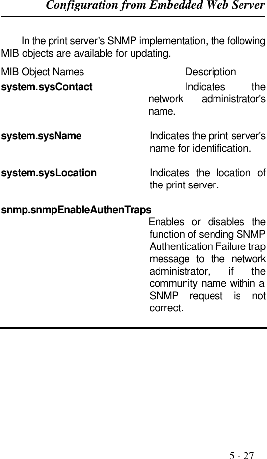
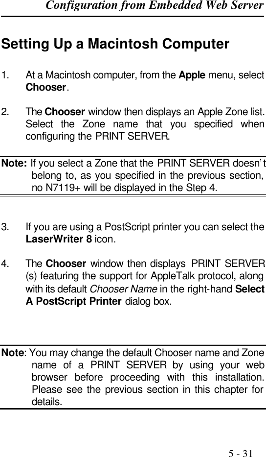
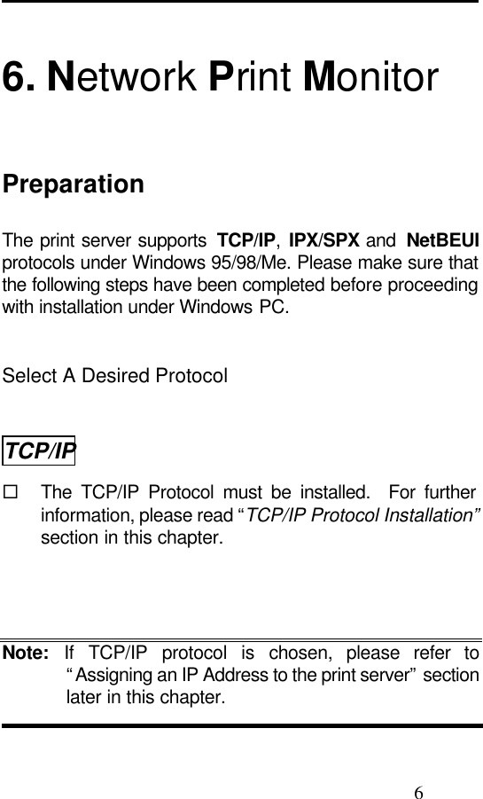
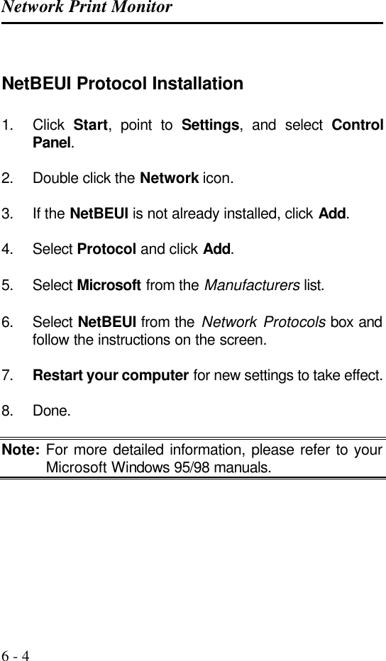
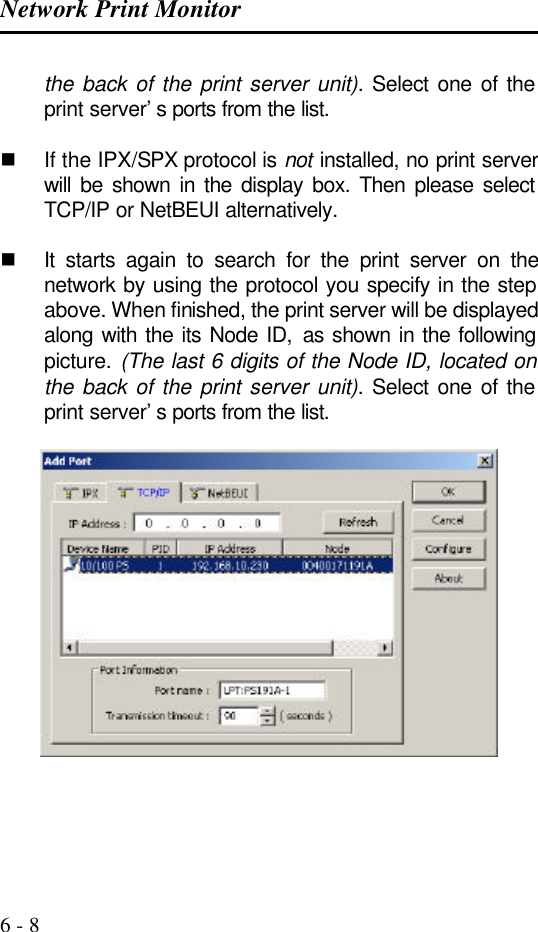
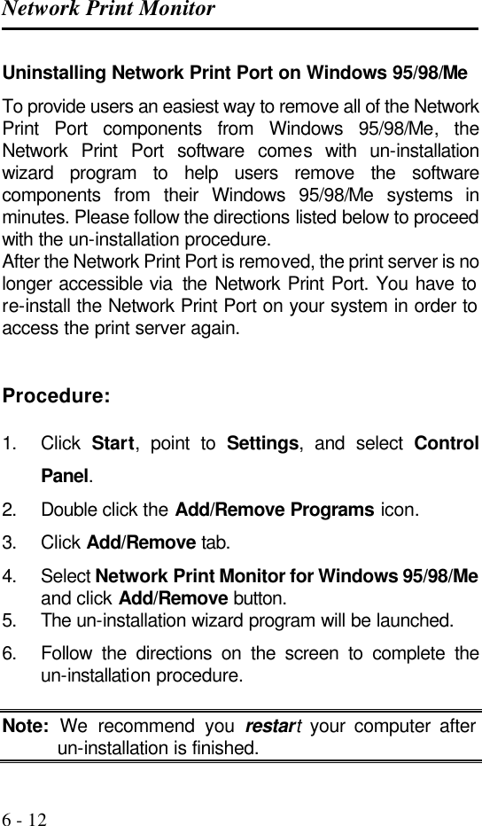
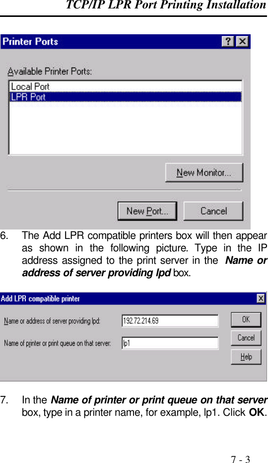
![The PSAdmin Utility for Windows-based 3 - 15 Multiple Print Queues Configuration To configure the print server to service multiple print queues, please follow the instructions listed below: 1. Log into your NetWare file server as a Supervisor (Admin.) or equivalent. 2. Run the PSAdmin from your Windows. 3. Select the print server and to be configured. 4. Click the Wizard icon in the tool bar. 5. Type in a Print server and a Print Queue Name (For more detailed information about Wizard, please refer to the “Wizard” section in this chapter). 6. Run the NetWare’s PCONSOLE and create additional print queues. 7. Select the Print server name you specify in Step 5. 8. Select the “Print server Configuration” option and select the ”Queue Serviced by Printer” option (For NetWare 4.x’s PCONSOLE, please select “Printers” option and select “Printer 0” instead). 9. Select the “Printer 0” and press the [Insert] key to add the print queues you create in Step 6 into the list (For NetWare 4.x’s PCONSOLE, please select “Print queues assigned” option instead). 10. Reset the print server by clicking the “Reset” icon from the PSAdmin. Done. Note: Please refer to NetWare’s Print server/Services manuals for detailed PCONSOLE commands.](https://usermanual.wiki/Zero-One-Technology-Co/WP02001/User-Guide-246543-Page-35.png)
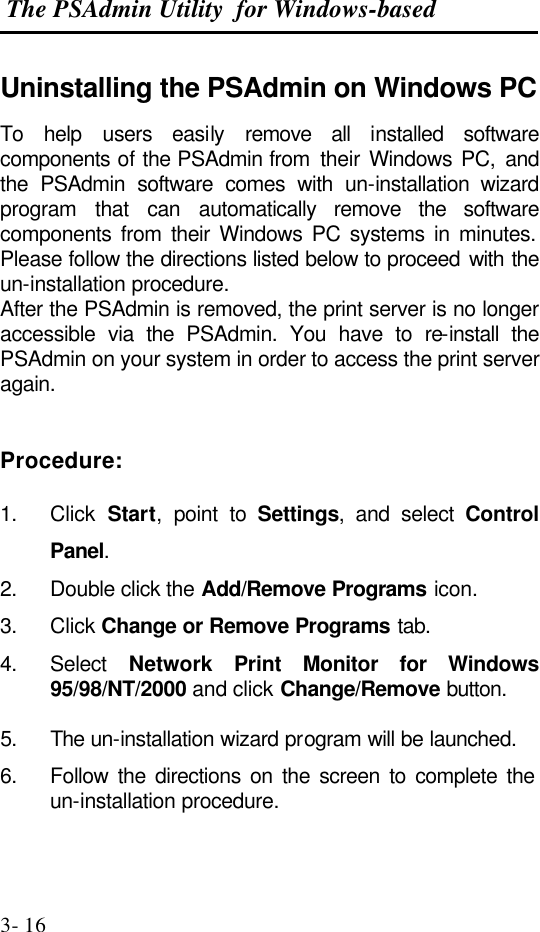
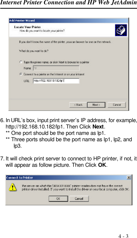
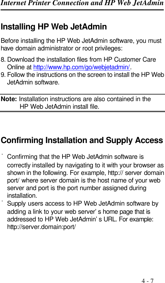
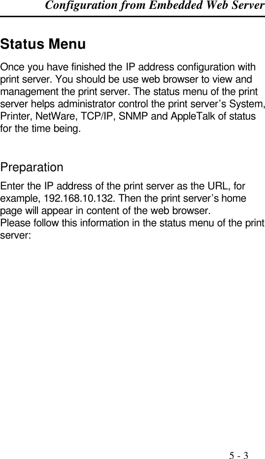
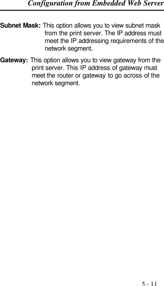
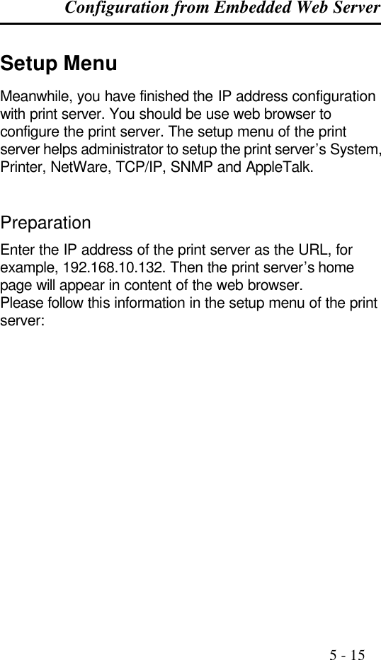
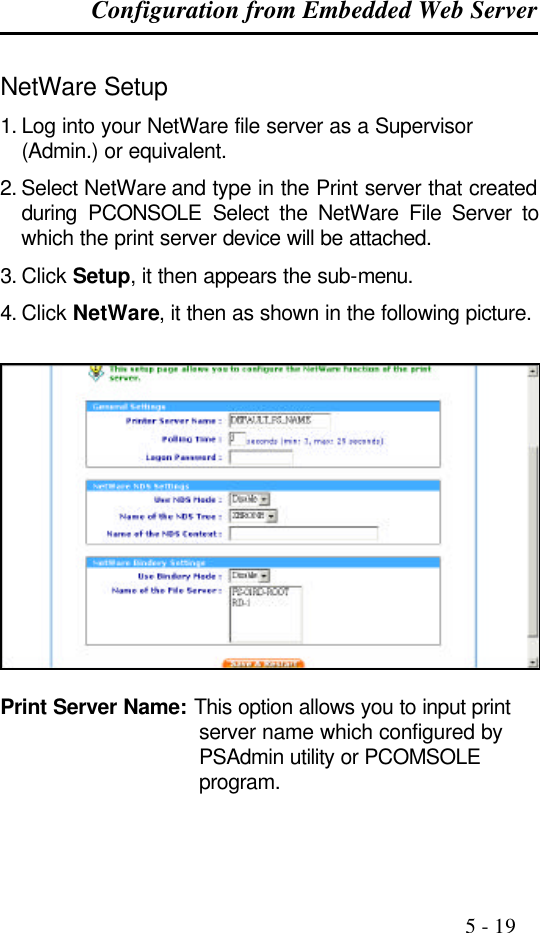
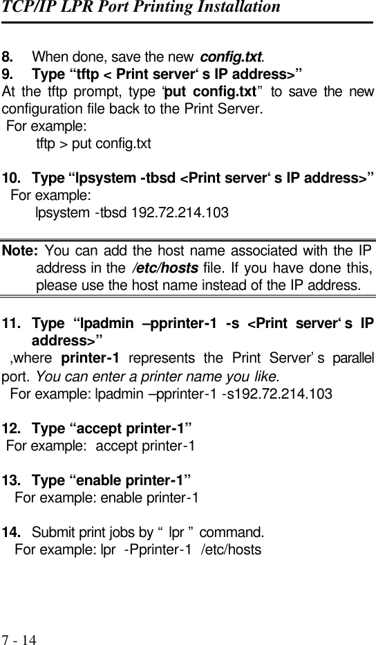
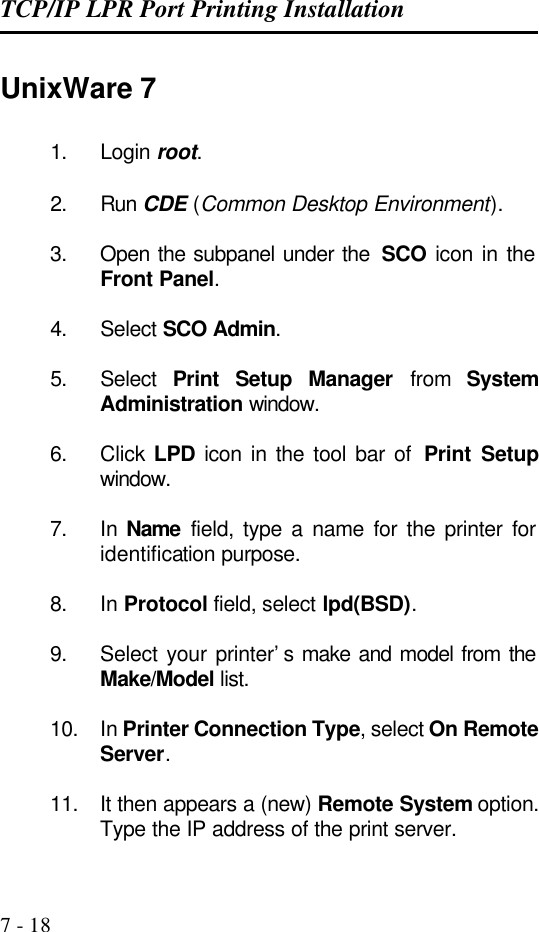
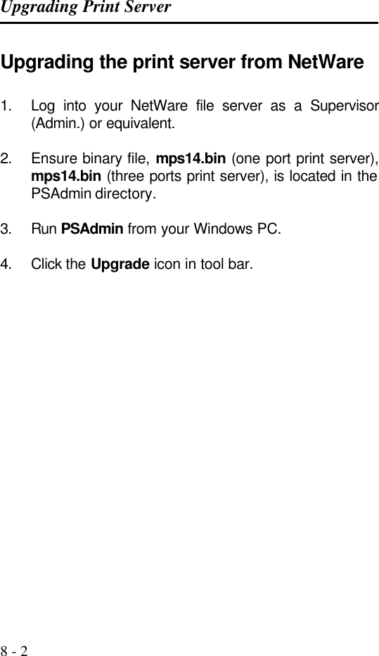
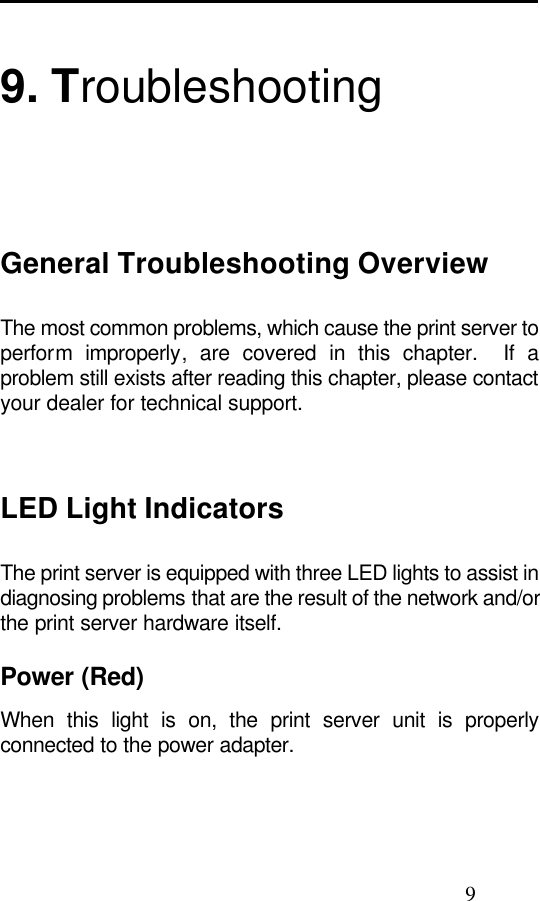
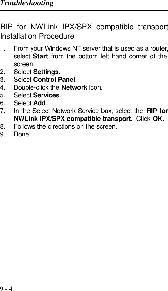
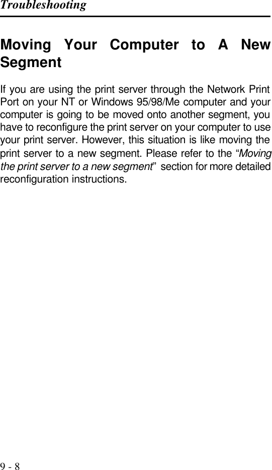
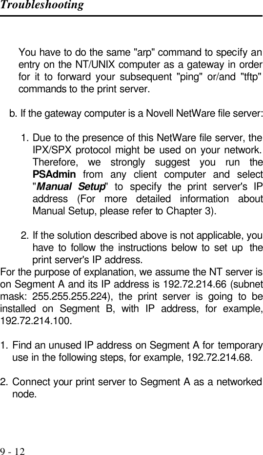
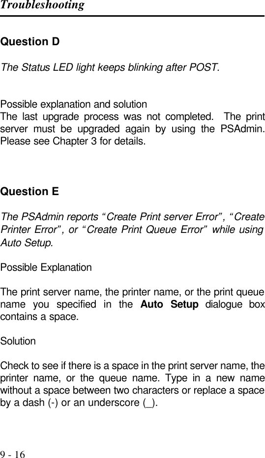
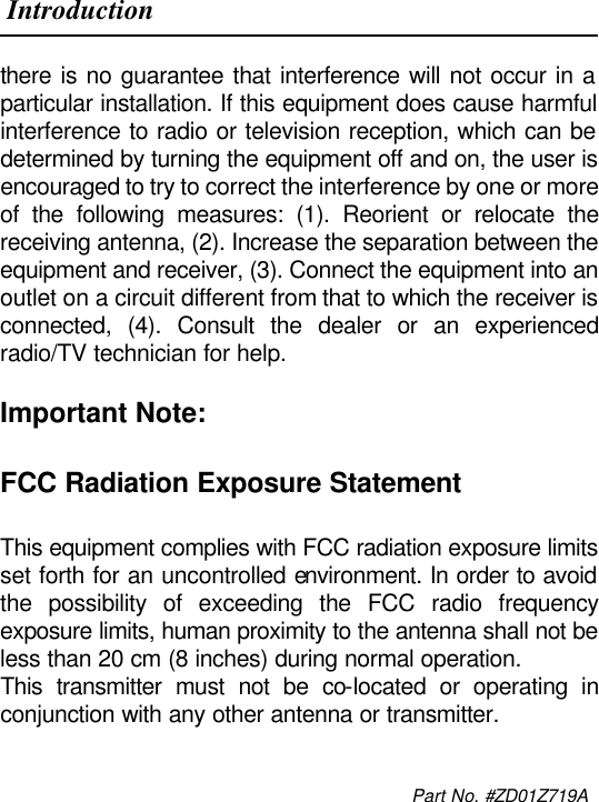
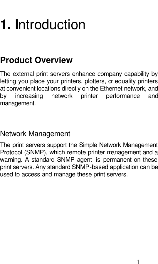
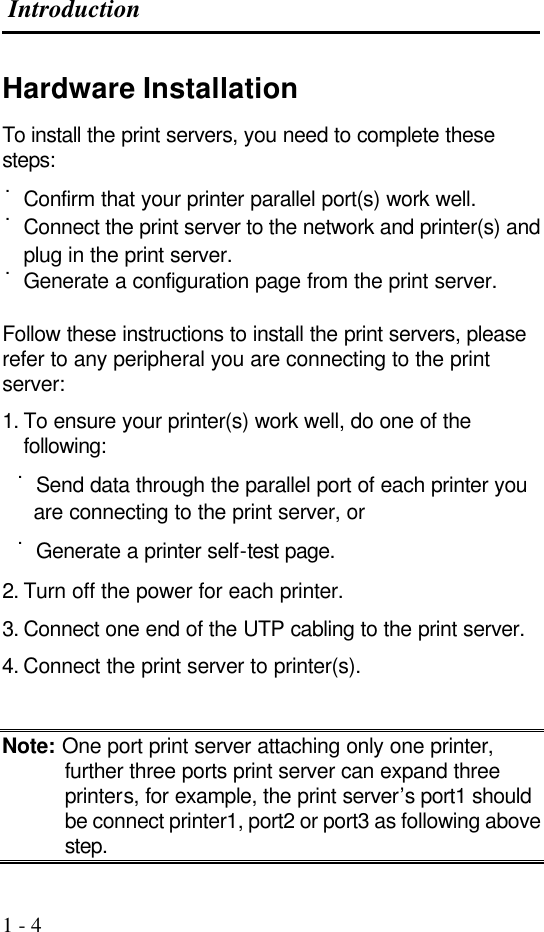
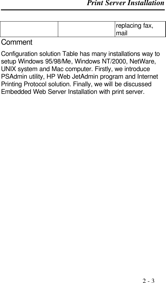
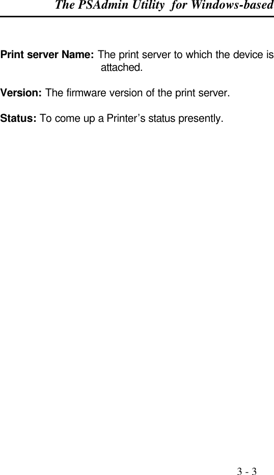
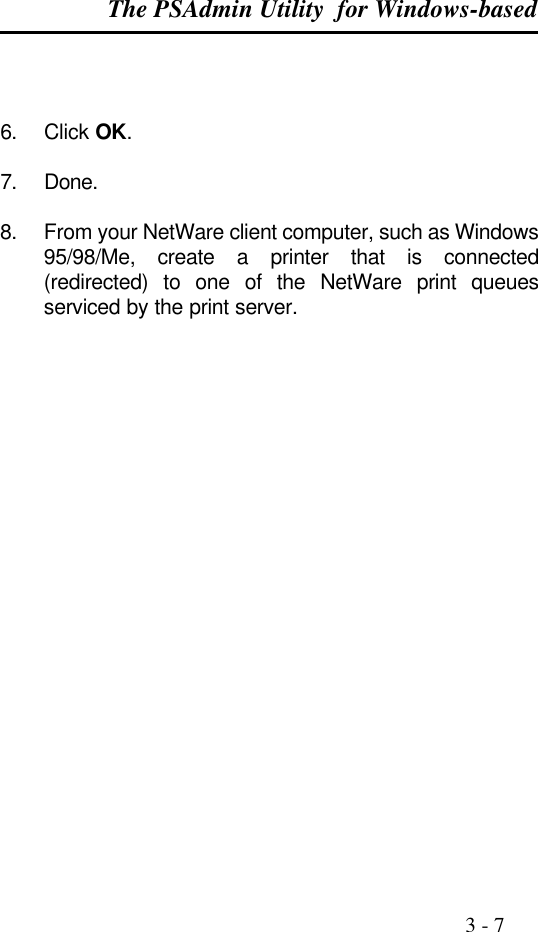
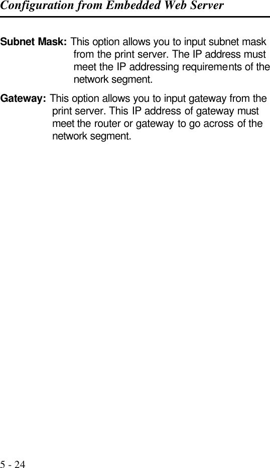
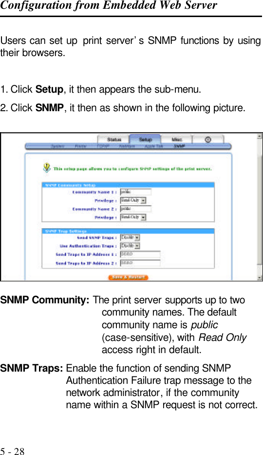
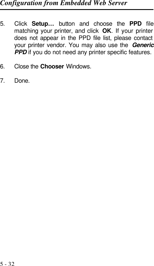
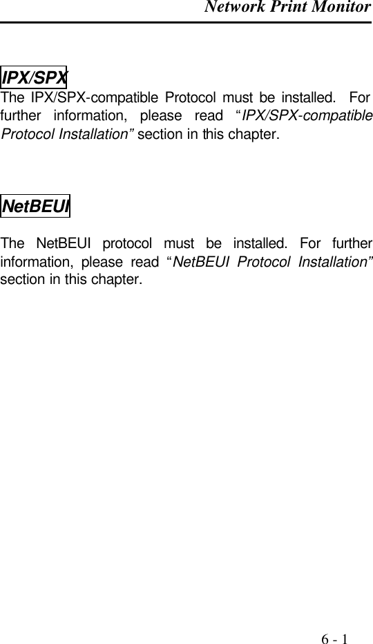
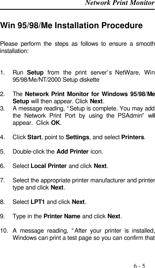
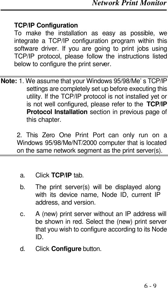
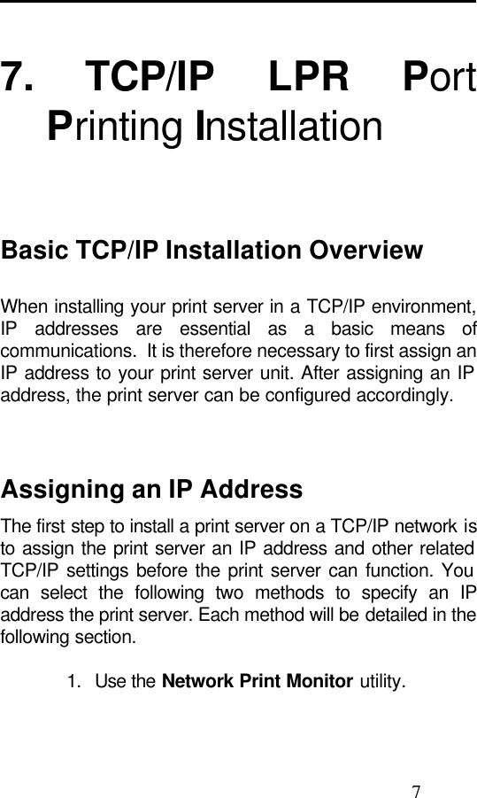
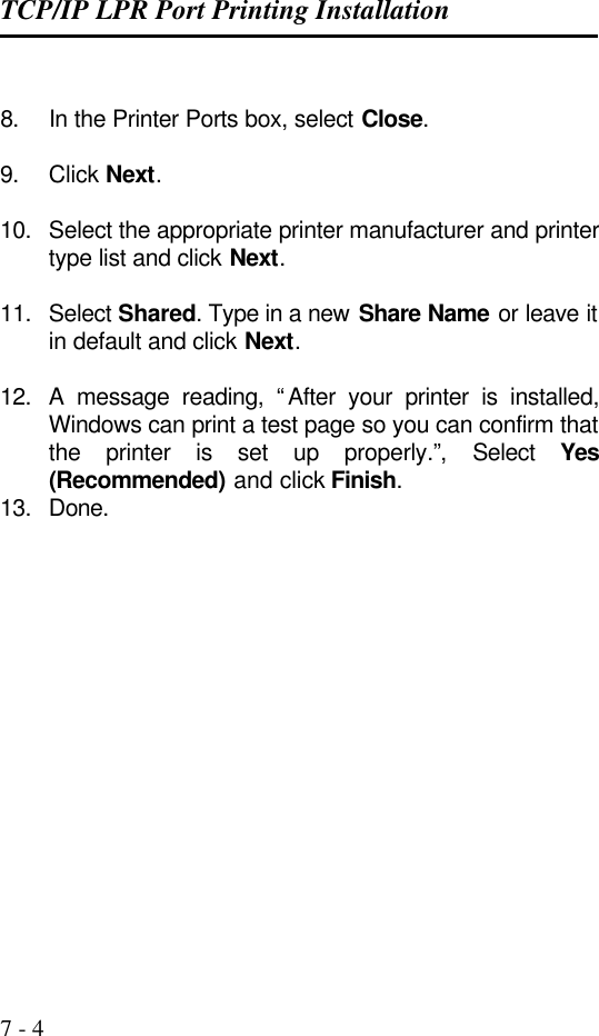
![Configuration from Embedded Web Server 5 - 21 Installing Print Server on NetWare 4.x/5.x Due to its architecture and functionality, the print server must work under NetWare 4.x/5.x NDS Bindery Emulation. When you install the NetWare file server for the first time, by default, the installation program will automatically set up the Bindery Emulation function for you by adding “SET BINDERY CONTEXT =” in the AUTOEXEC.NCF file. By default, the bindery context will only be set on your organization (O) object. If you have ever modified this line, or if you have ever added any organization units (OU) to your NDS tree after the NetWare system was installed, please read the following section before you install the print server. For the purpose of illustration, we assume the NDS tress structure is as follows: [ROOT] (O)ABC (OU)ABC-USA (OU)Sales Admin FileServer-1 (OU) Tech](https://usermanual.wiki/Zero-One-Technology-Co/WP02001/User-Guide-246543-Page-67.png)
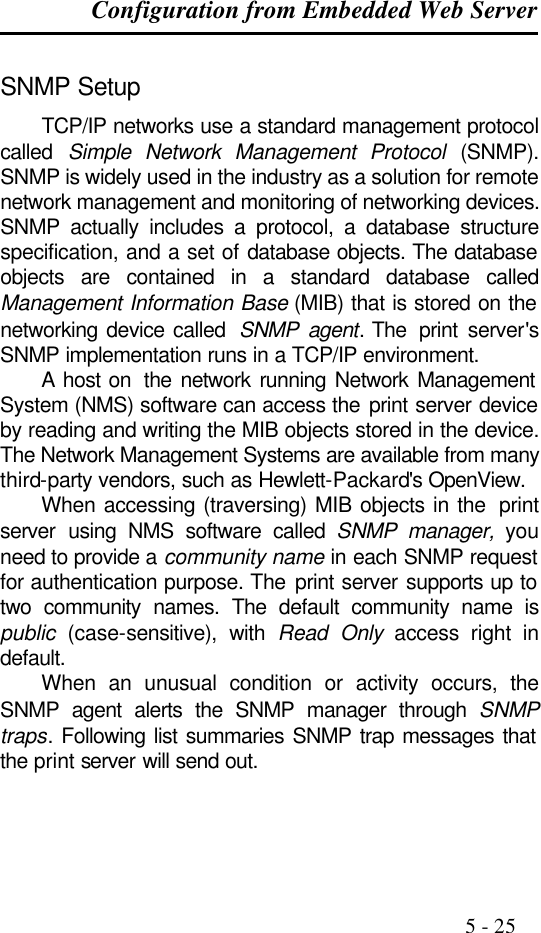
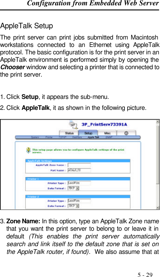
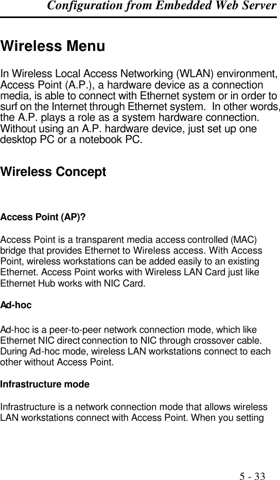
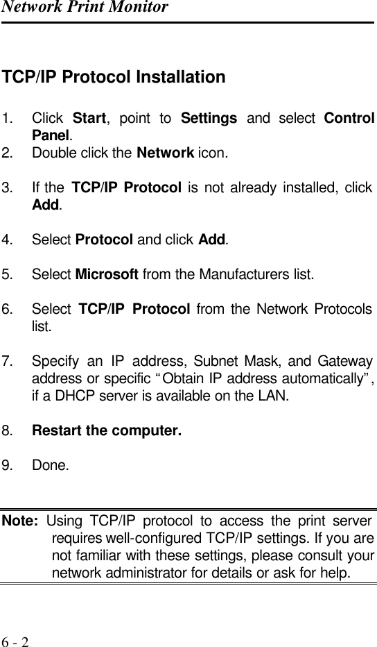
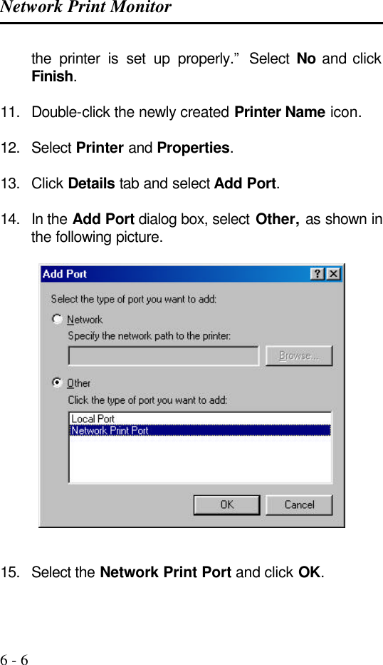
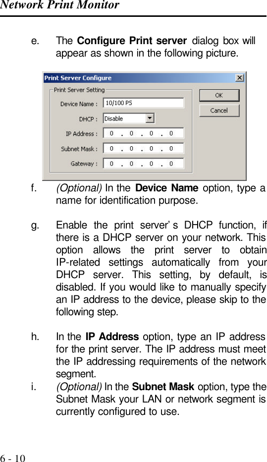
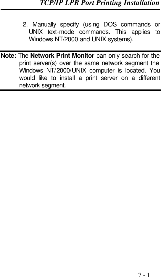
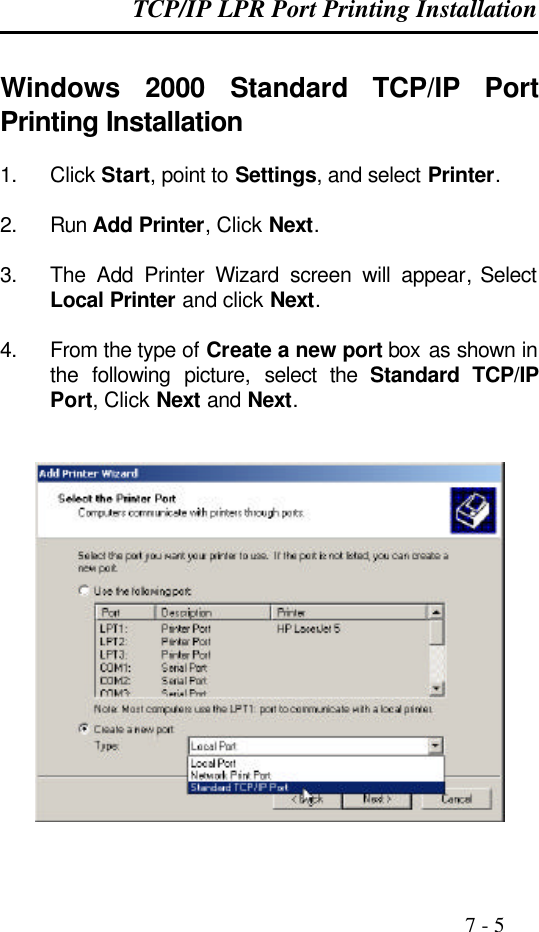
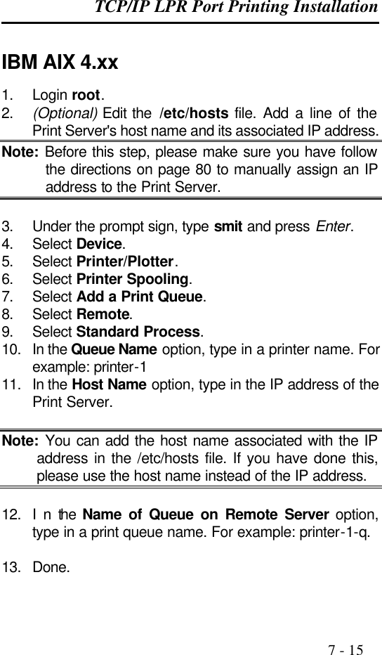
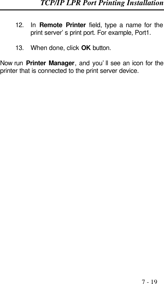
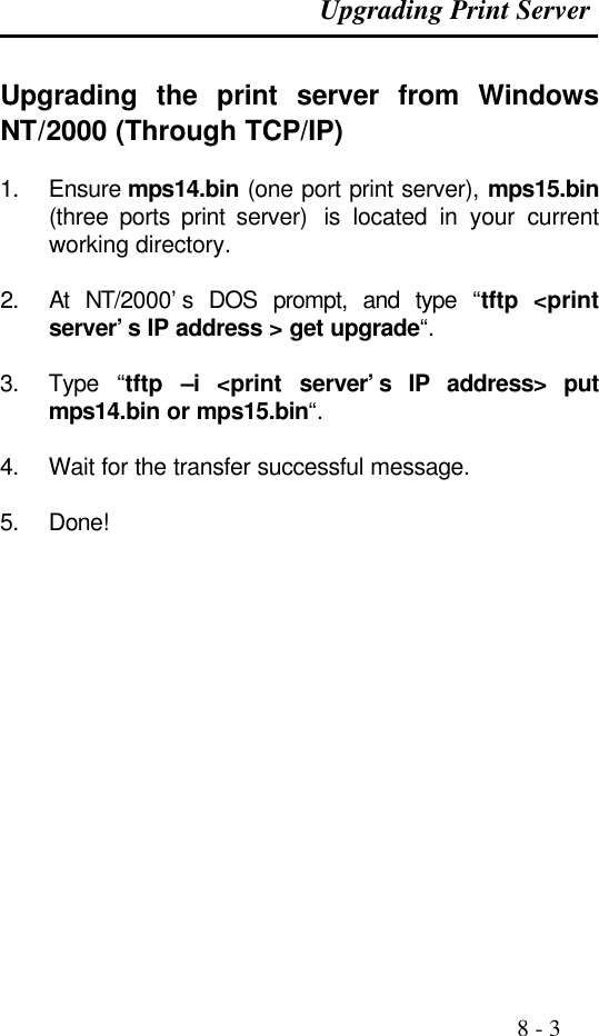
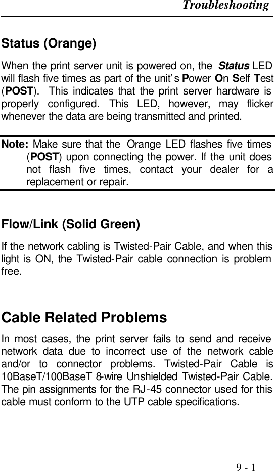
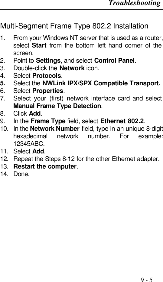
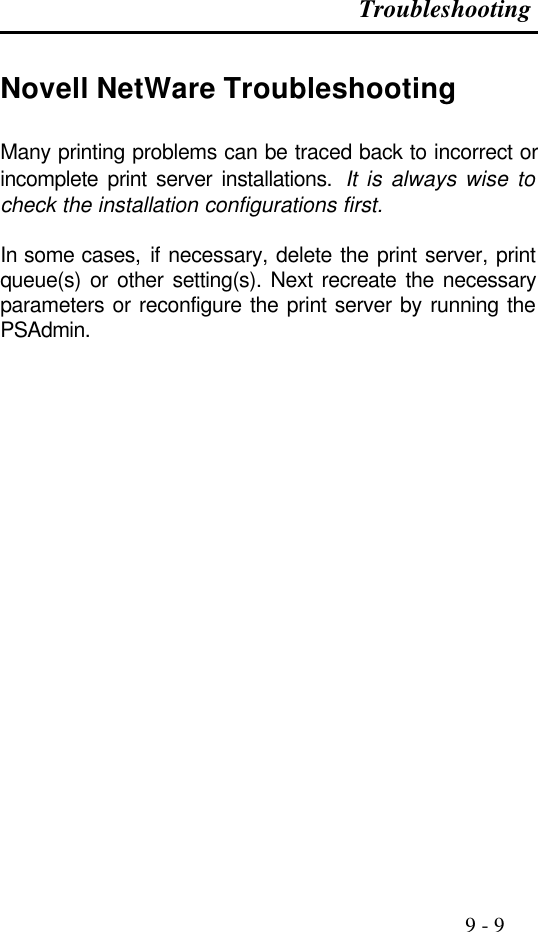
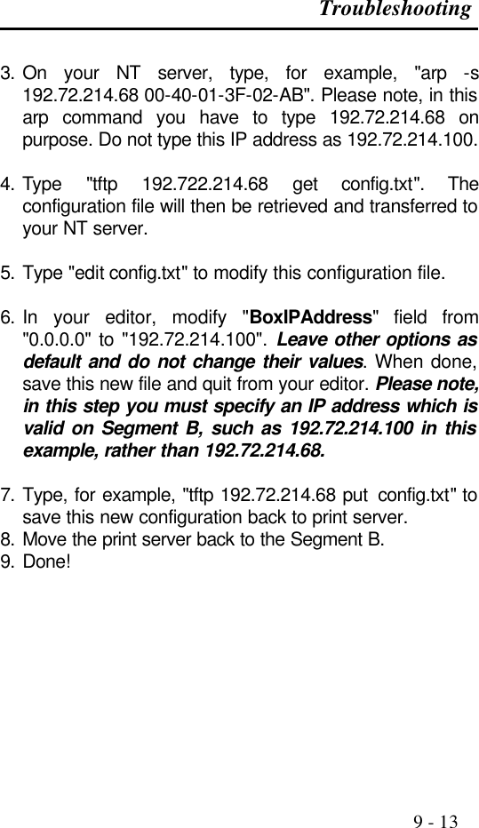
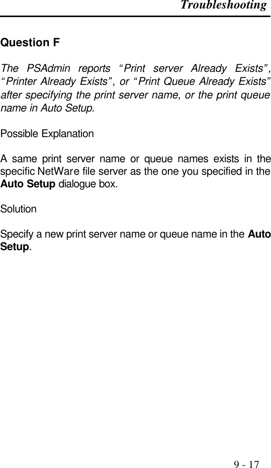
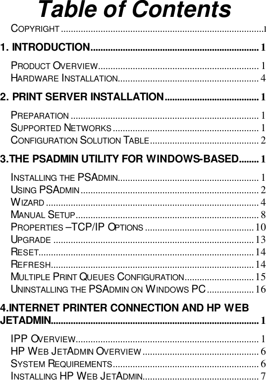
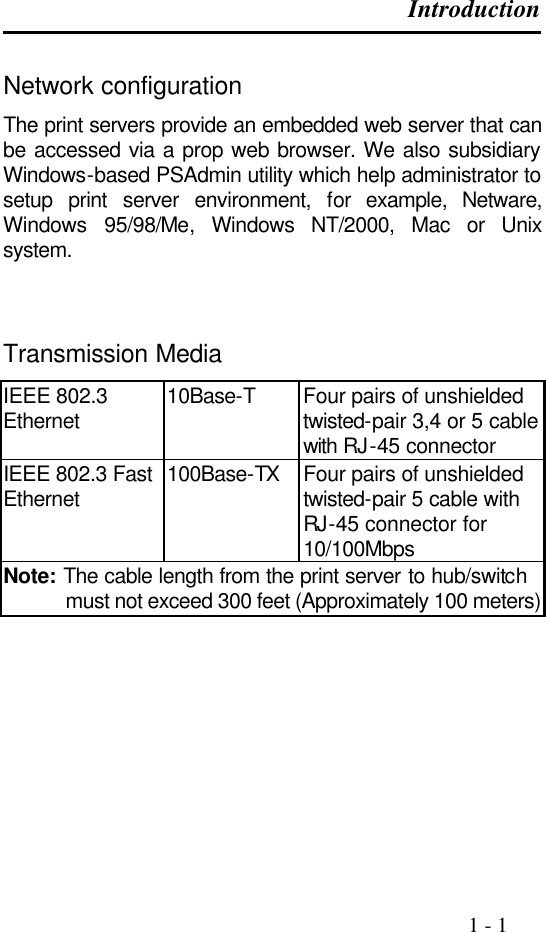
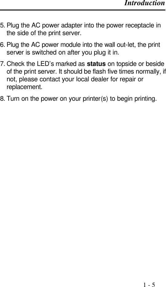
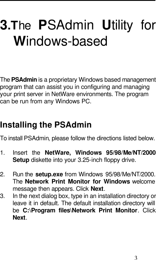
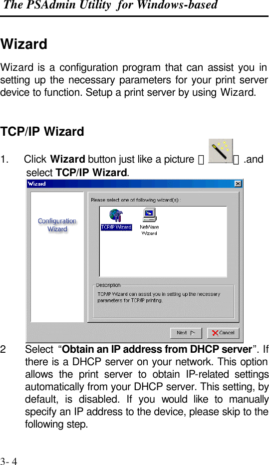
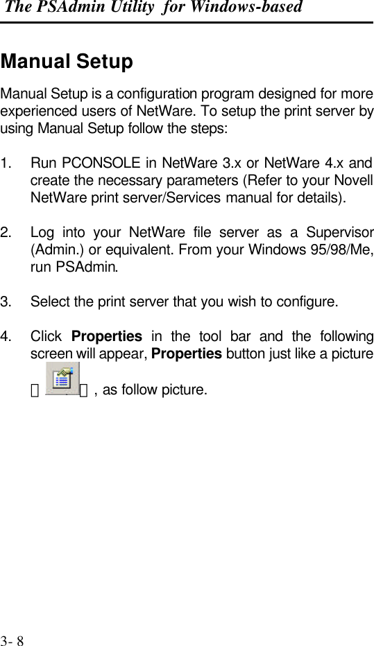
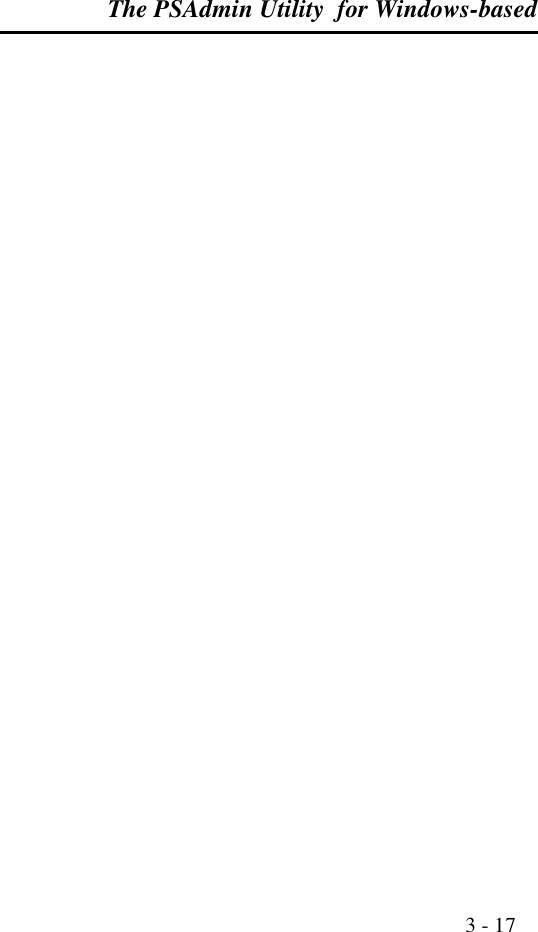
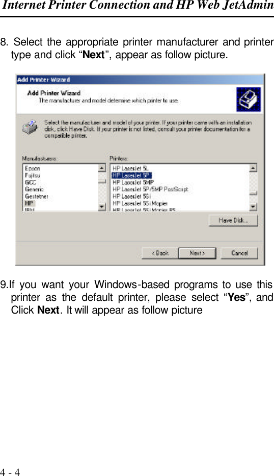
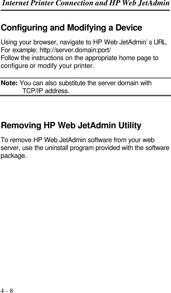
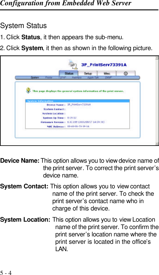
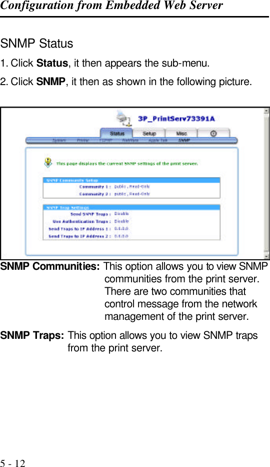
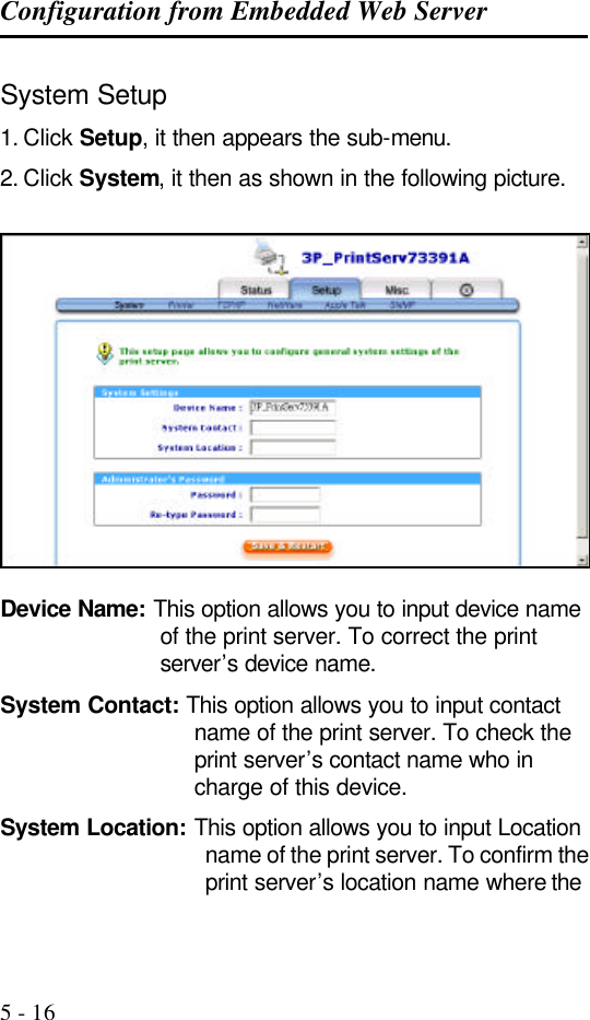
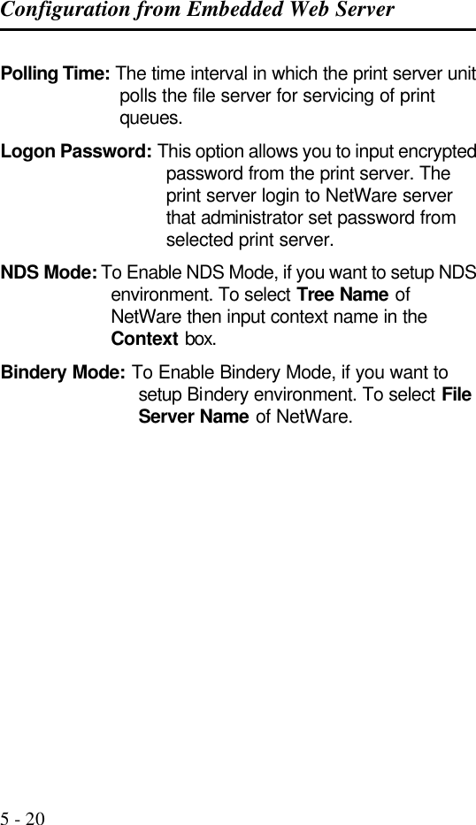
![TCP/IP LPR Port Printing Installation 7 - 11 At the tftp prompt, type “get config.txt” to retrieve the Print Server‘s configuration file. For example: tftp > get config.txt 5. Quit from tftp, and then use your editor to modify the “05 BoxIPAddress” field in the config.txt file from 0.0.0.0 to the IP address you specify in Step 2. 6. (Optional) Modify the "06 Gateway" field from 0.0.0.0 to your gateway's IP address. 7. (Optional) Modify the "07 SubnetMask" field from 0.0.0.0 to the subnet mask. 8. When done, save the new config.txt. 9. Type “tftp < Print server‘s IP address>” At the tftp prompt, type “put config.txt” to save the new configuration file back to the Print Server. For example: tftp > put config.txt 10. Type “mkdev rlp” After this step, the Remote Printer Configuration appears. Answer the questions as follows: a. Do you want to install or remove printing (i/r/q) ? [q] : -----> i b. Do you wish to change the printer description file /etc/printcap (y/n) [n] ? ---------> y c. Enter information for remote printers or local printers accepting remote printing requests](https://usermanual.wiki/Zero-One-Technology-Co/WP02001/User-Guide-246543-Page-113.png)
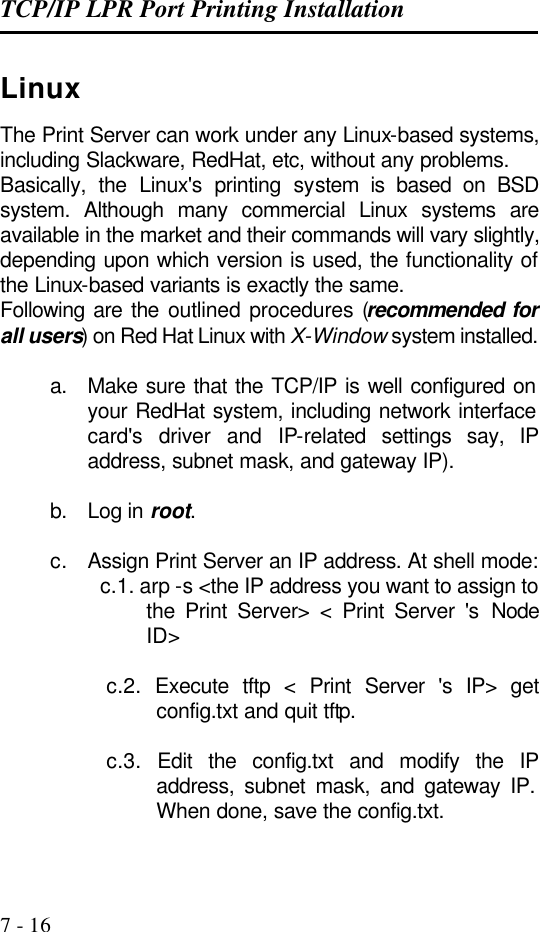
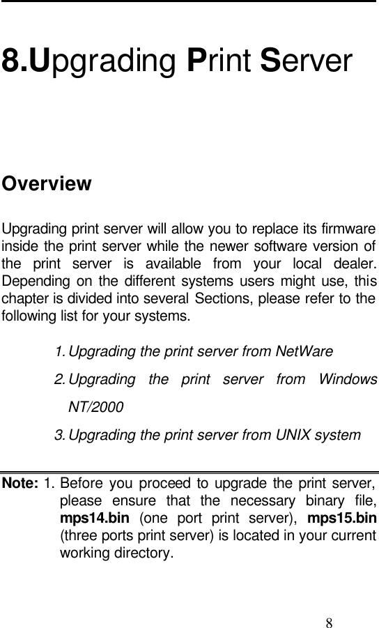
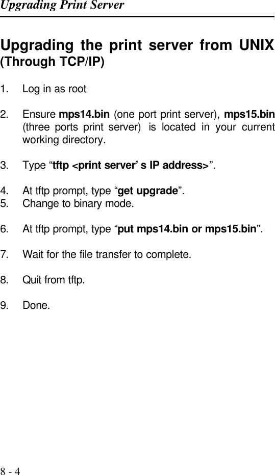
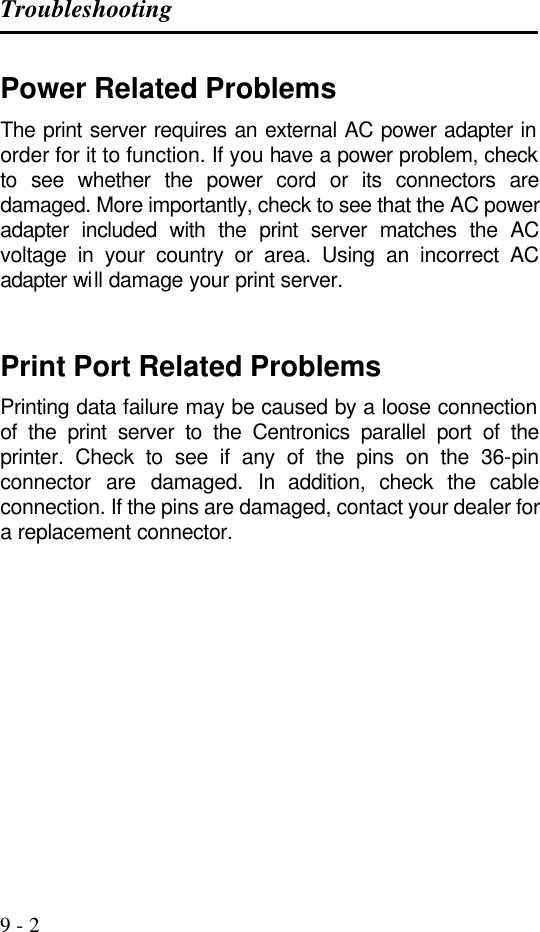
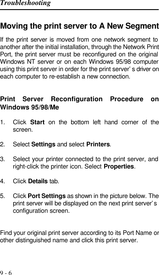
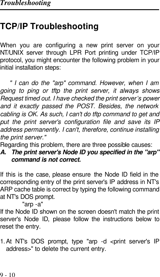
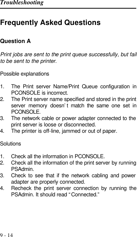
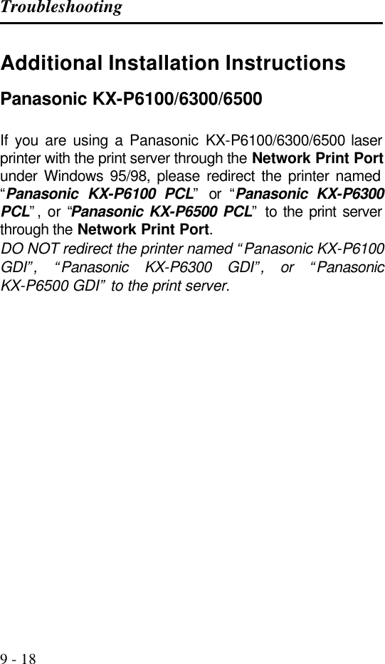
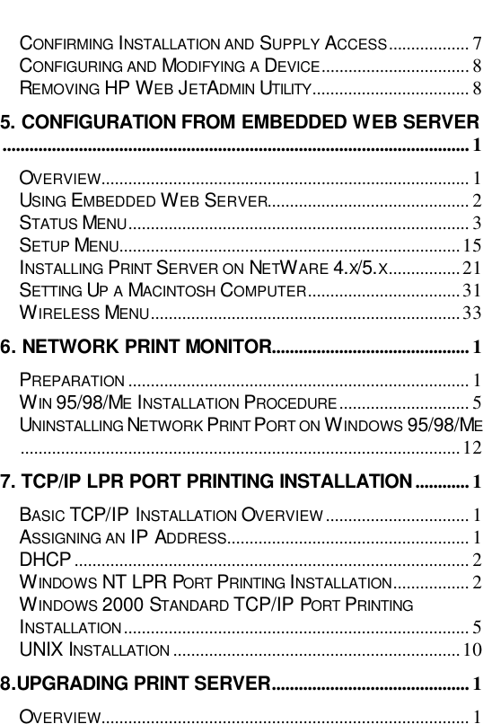
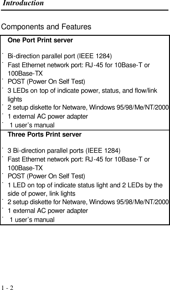
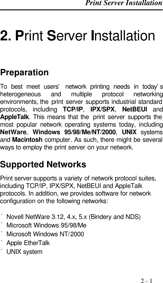
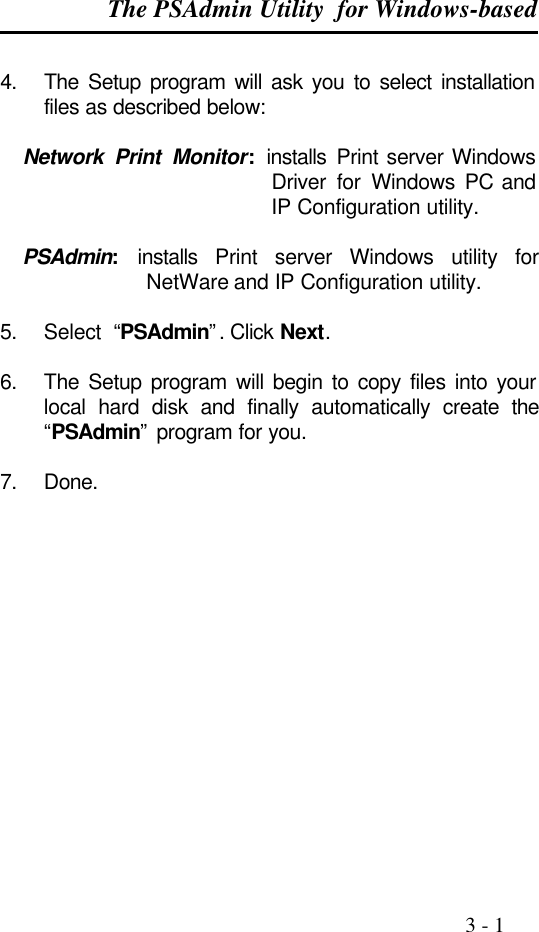
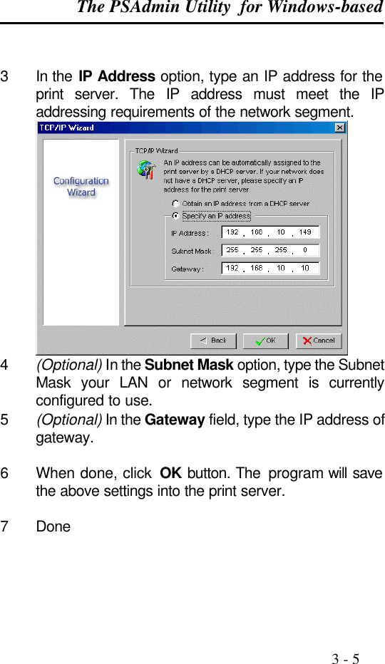
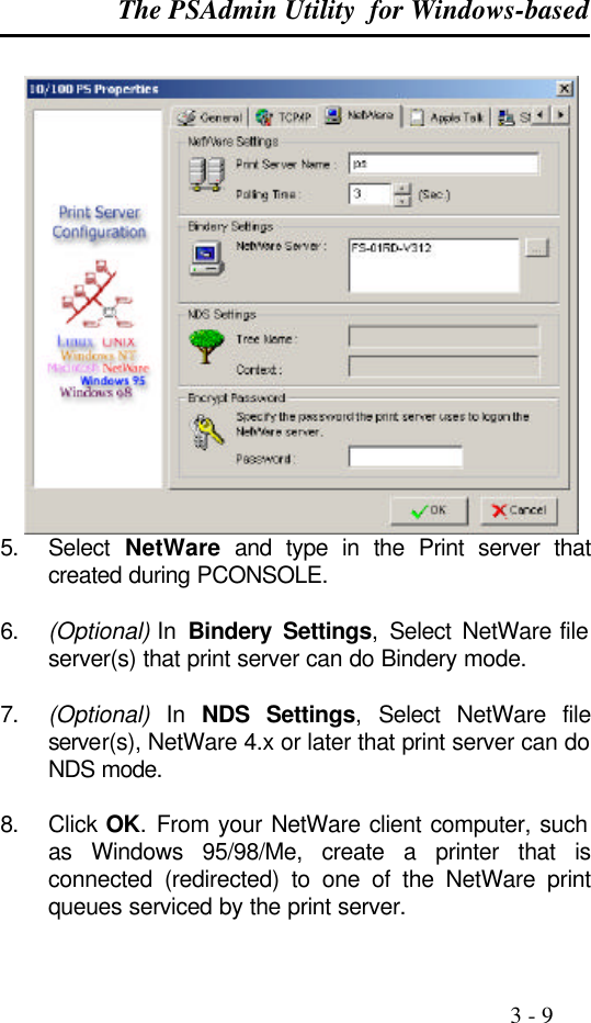
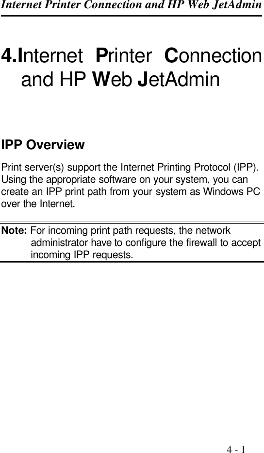
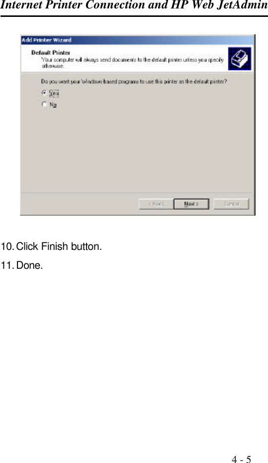
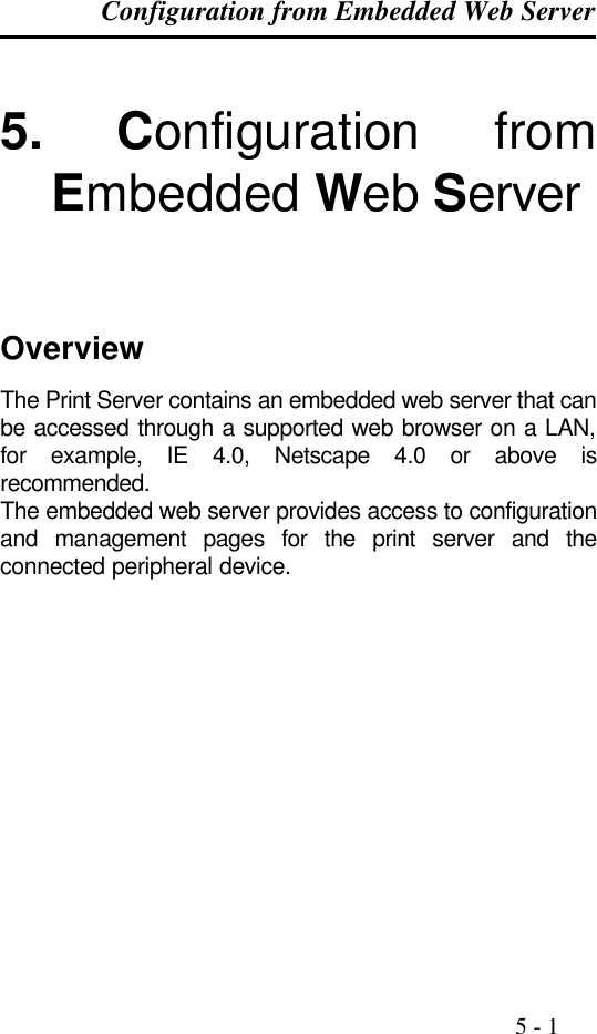
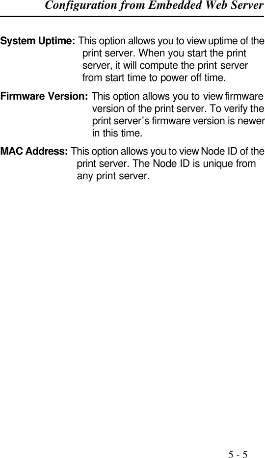
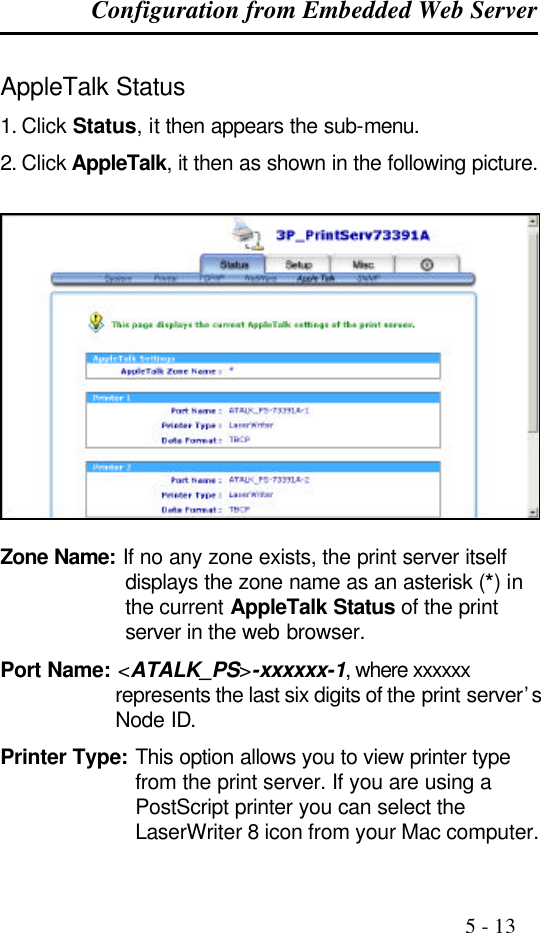
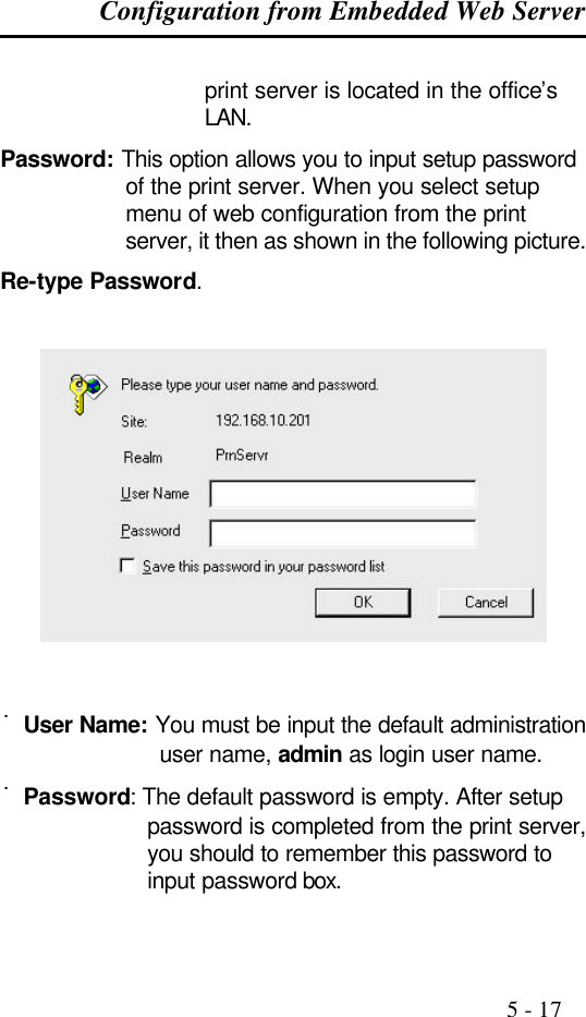
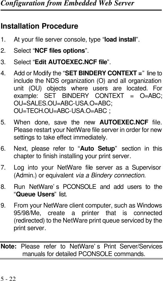
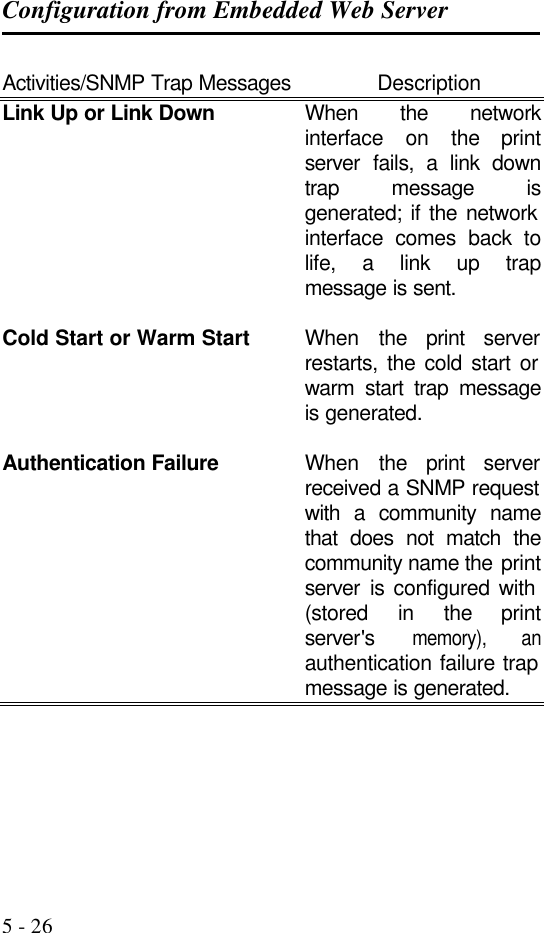
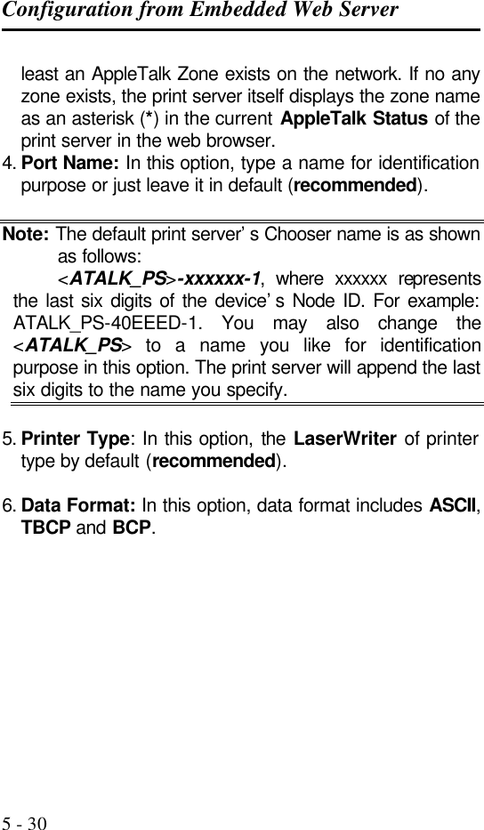
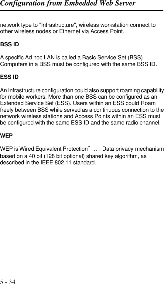
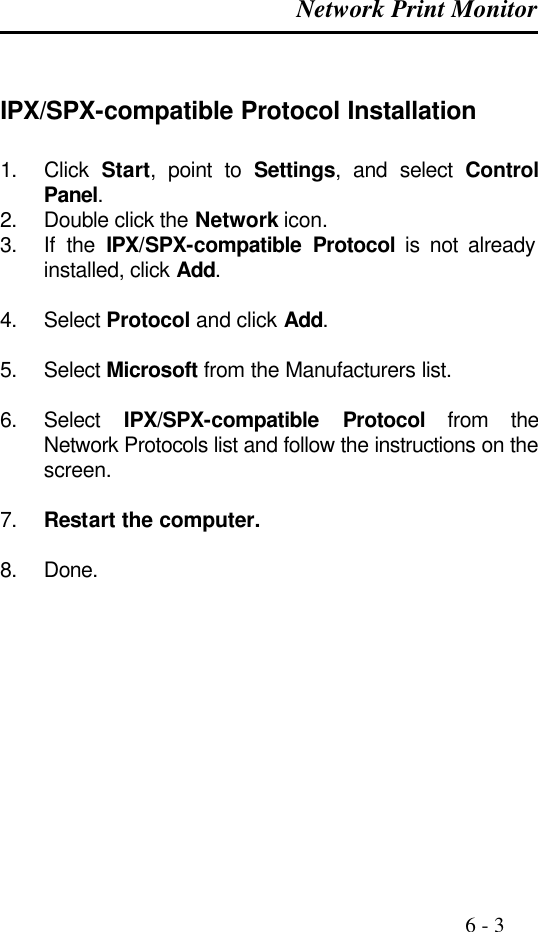
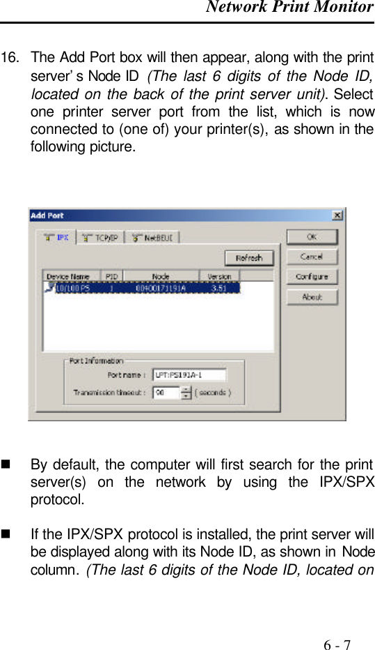
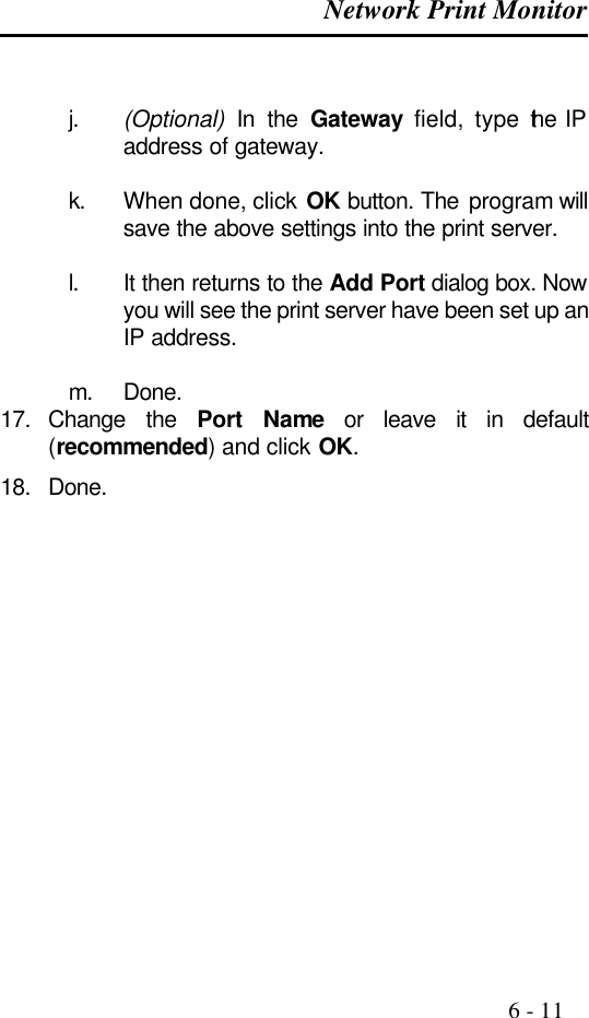
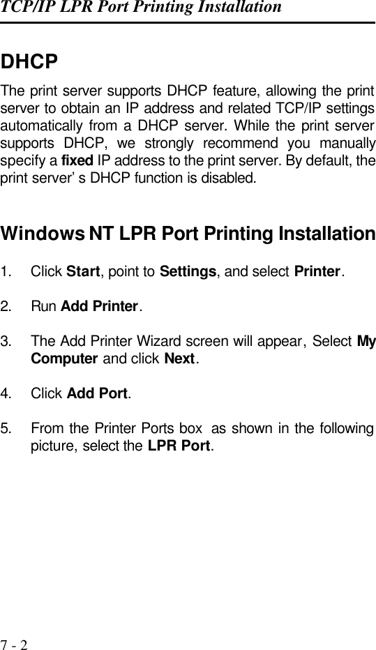
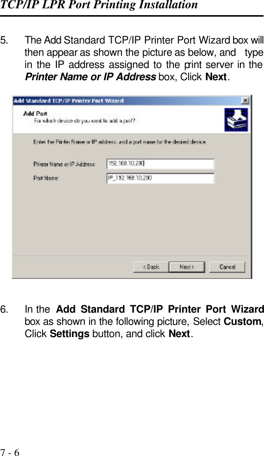
![TCP/IP LPR Port Printing Installation 7 - 12 Please enter the printer name (q to quit): --->printer-1 You can enter a printer name you like in this option. d. Is xxxx a remote printer or a local printer (r/l) ---------> r e. Please enter the name of the remote host that xxxx is attached to: ---------> the Print server‘s IP address you specified in Step 2, for example, 192.72.214.103 Note: You can add the host name associated with the IP address in the /etc/hosts file. If you have done this, please use the host name instead of the IP address. f. Printer xxxx is connected to host 192.72.214.103 Is this correct ? (y/n) ---------> y g. After it shows some messages, it will ask you a question. If you‘re not sure, answer ’n‘ ? (y/n) [n] --------> n h. Would you like this to be the system default printer ? (y/n) [n]------->answer this question if you like to make it as a default printer. i. Do you want to install or remove printing (i/r/q) ? [q] : -------> q j. Do you want to star remote daemon now (y/n) --------> y 11. Done. Submit print jobs by using “lp” or “lpr” command. For example: lp -d printer-1 /etc/printcap](https://usermanual.wiki/Zero-One-Technology-Co/WP02001/User-Guide-246543-Page-114.png)