Zhejiang Dahua Technology DH-HWS Radar Speed Measuring System User Manual
Zhejiang Dahua Technology Co. Ltd. Radar Speed Measuring System Users Manual
UserManual.wiki
>
Zhejiang Dahua Technology
>
DH HWS User Manual
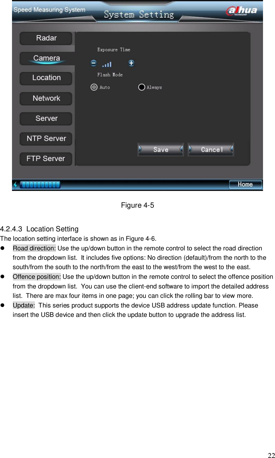
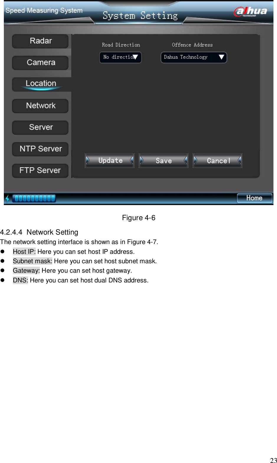
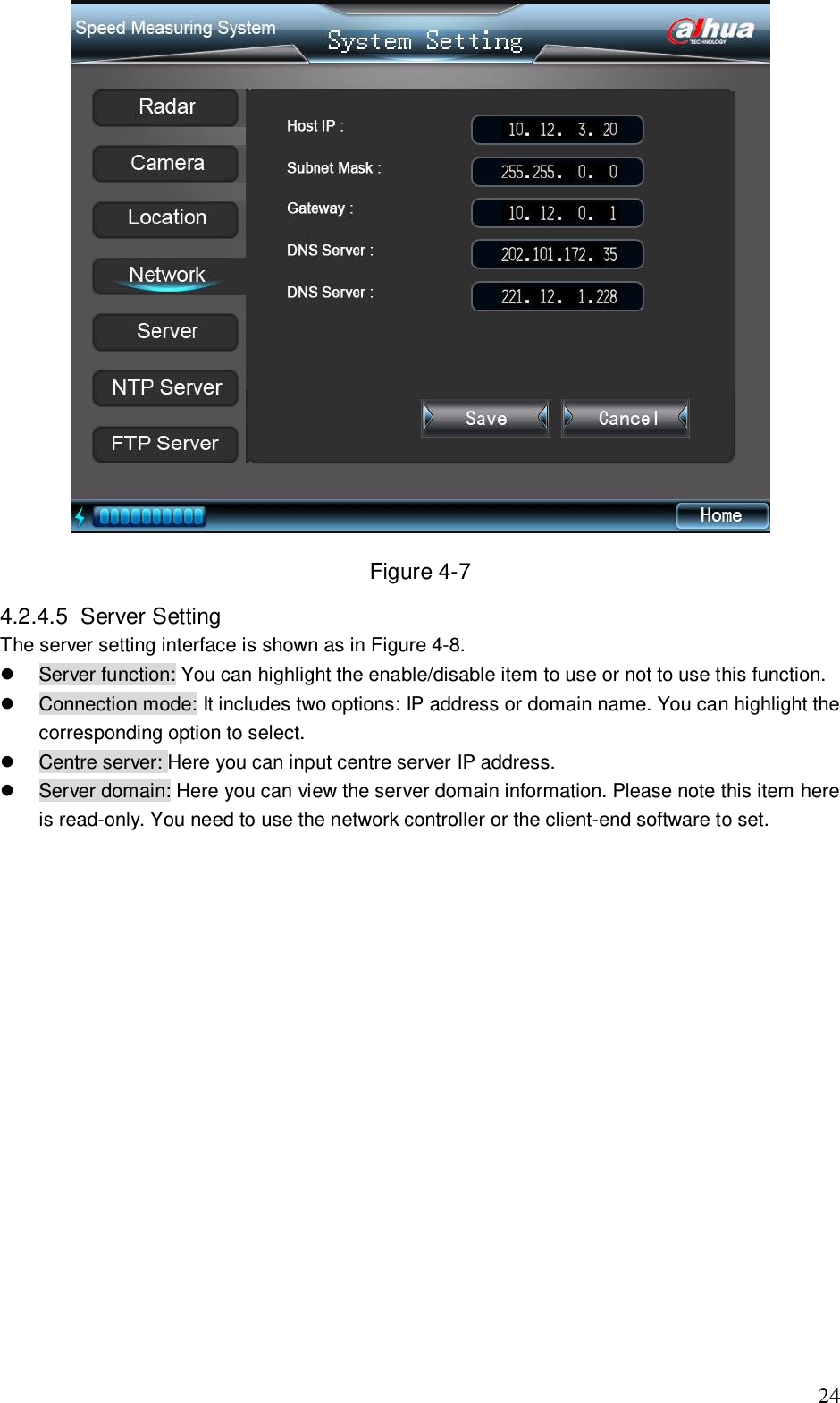
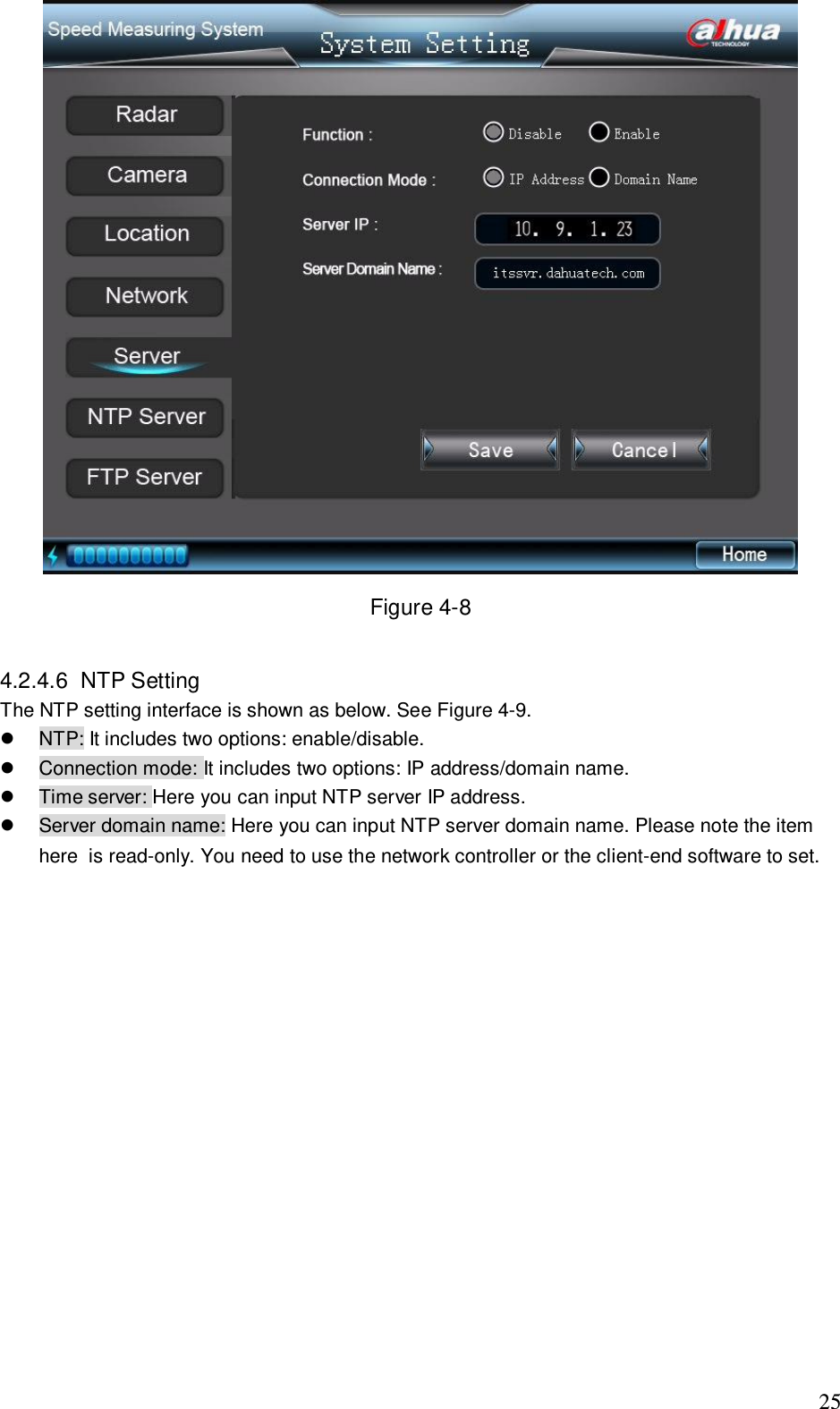
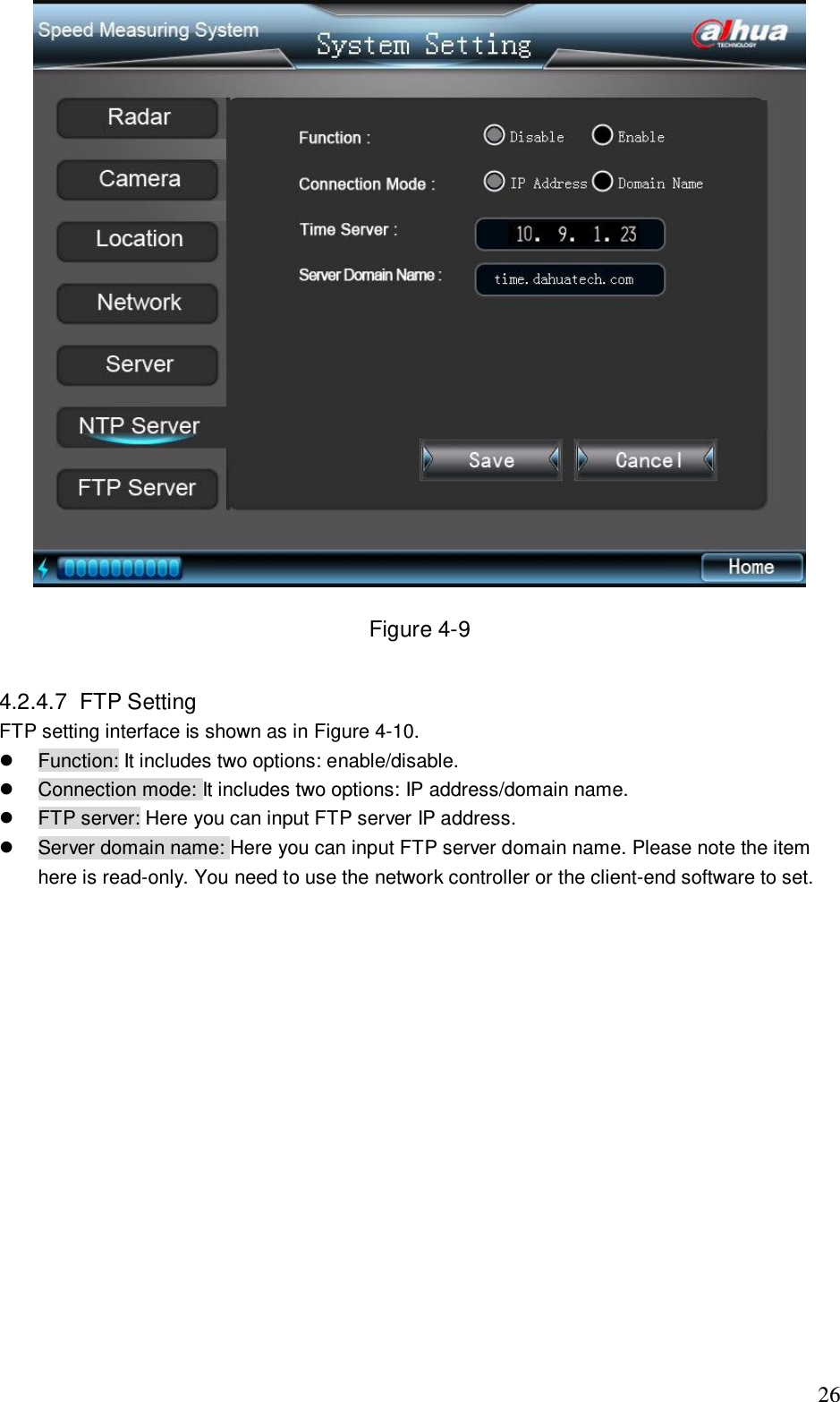
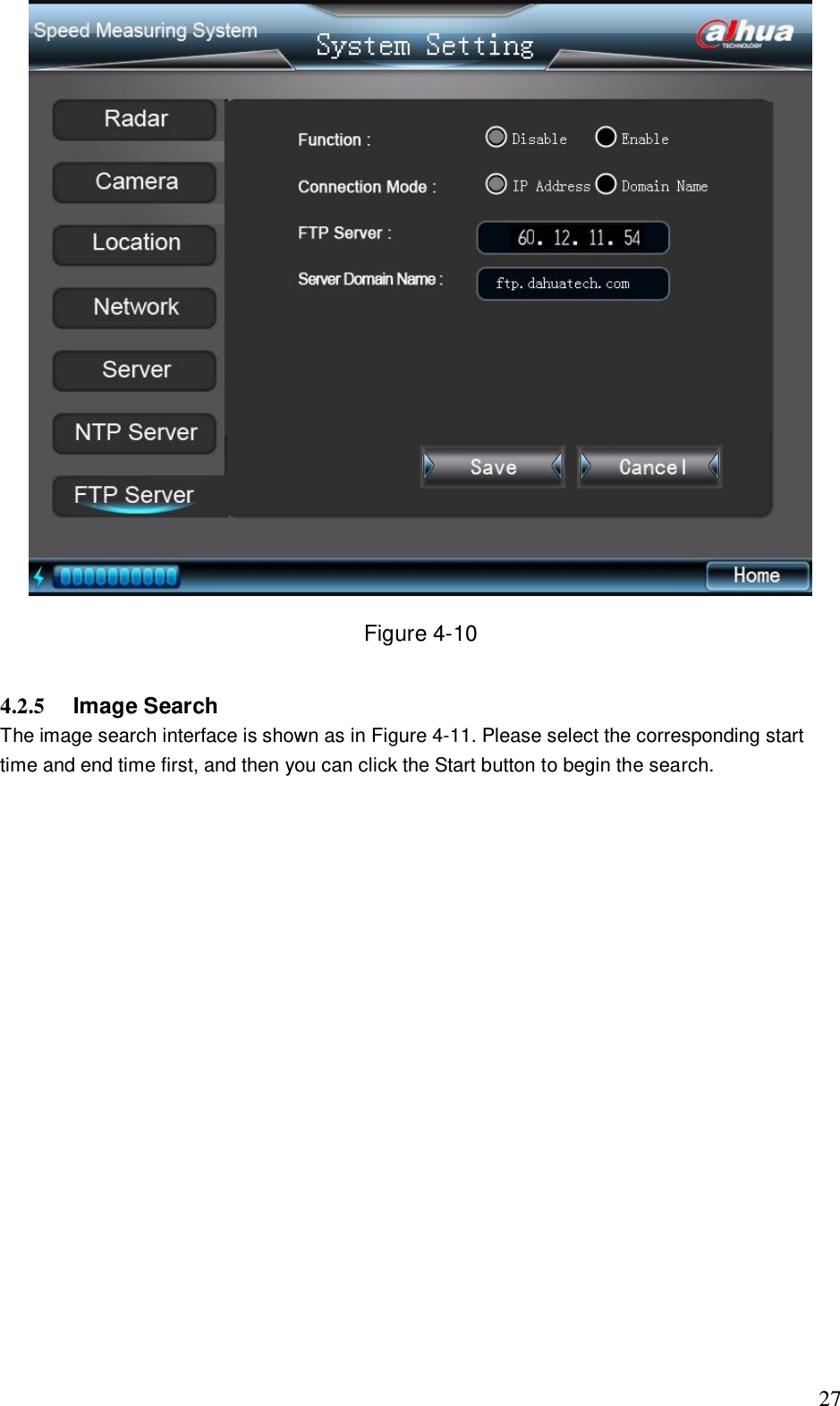
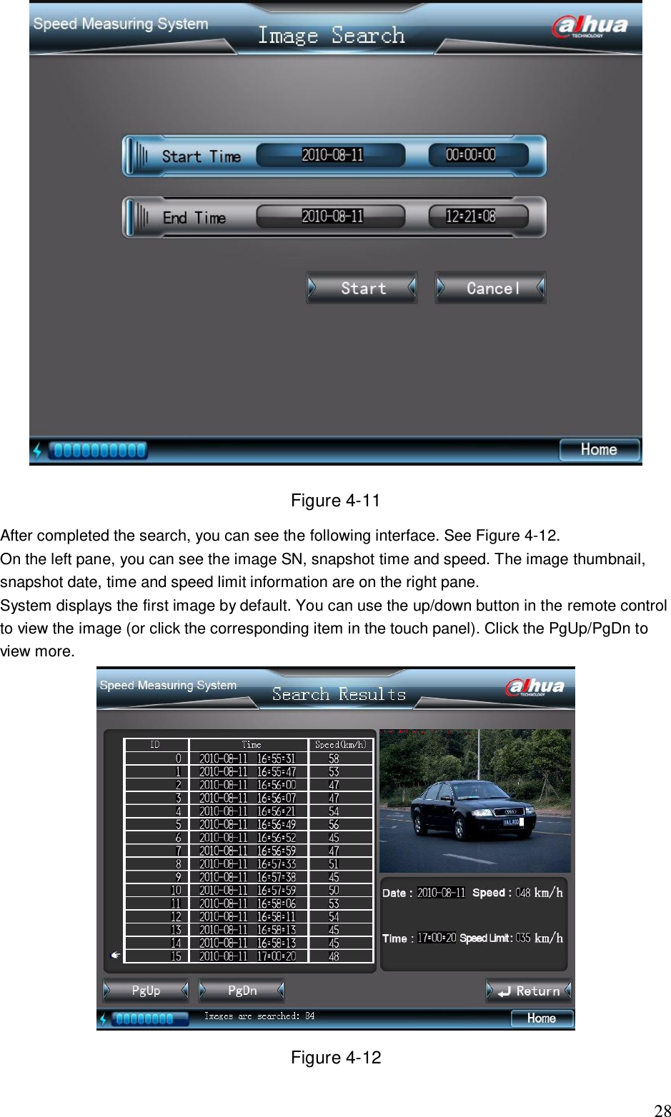
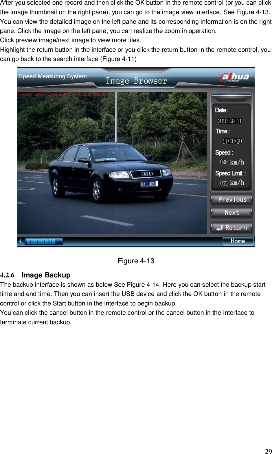
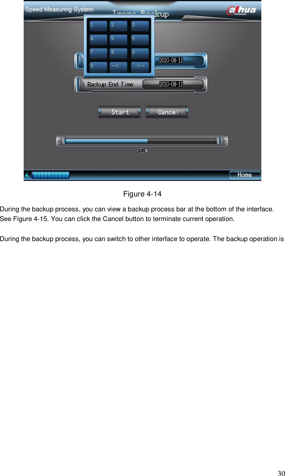
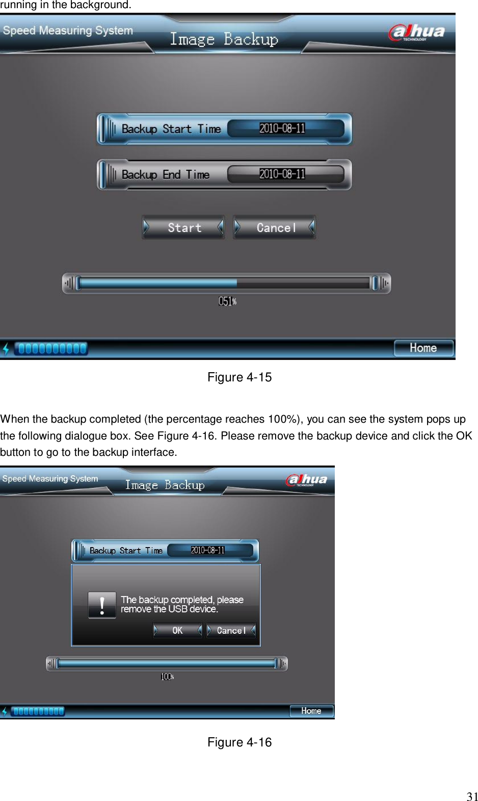
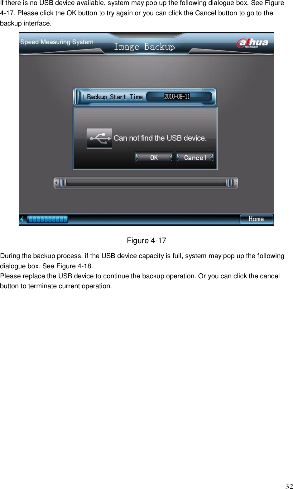
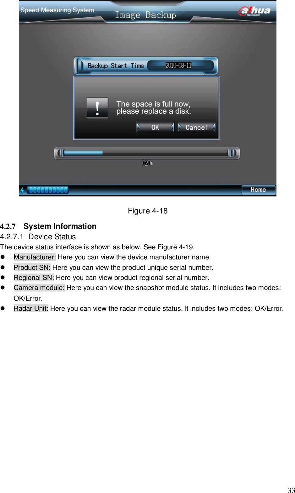
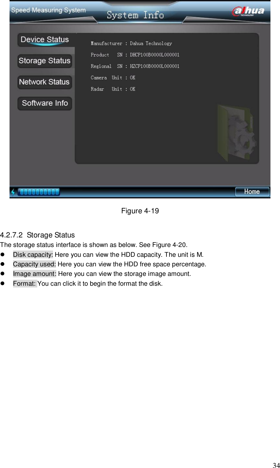
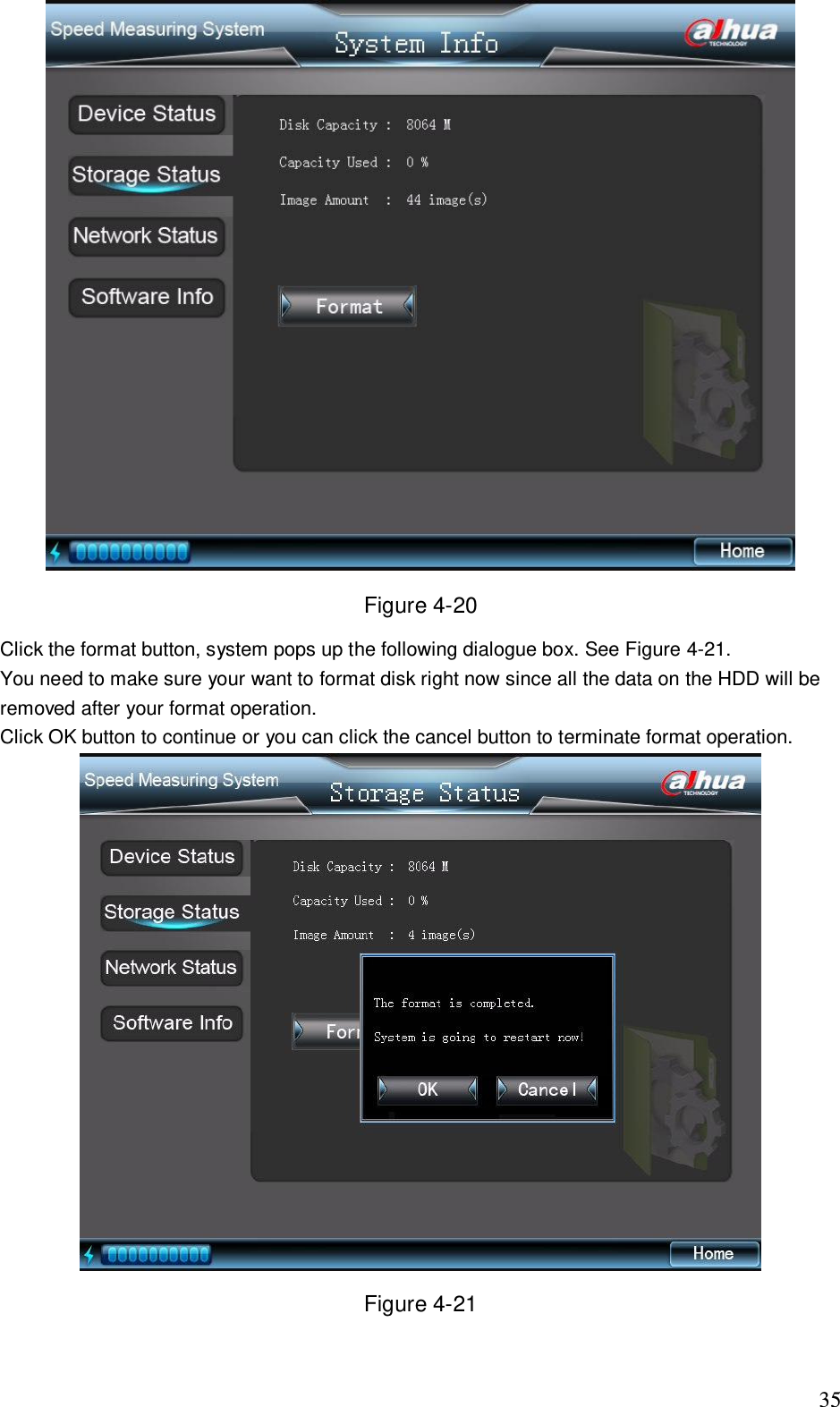
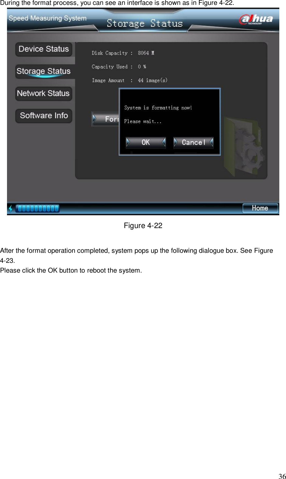
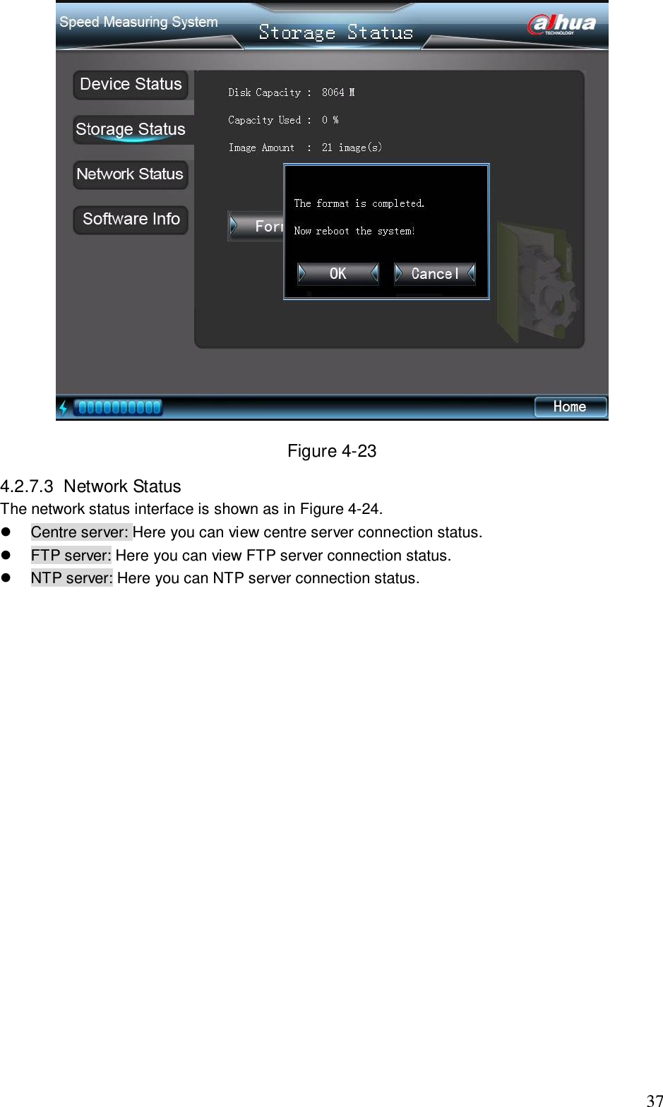
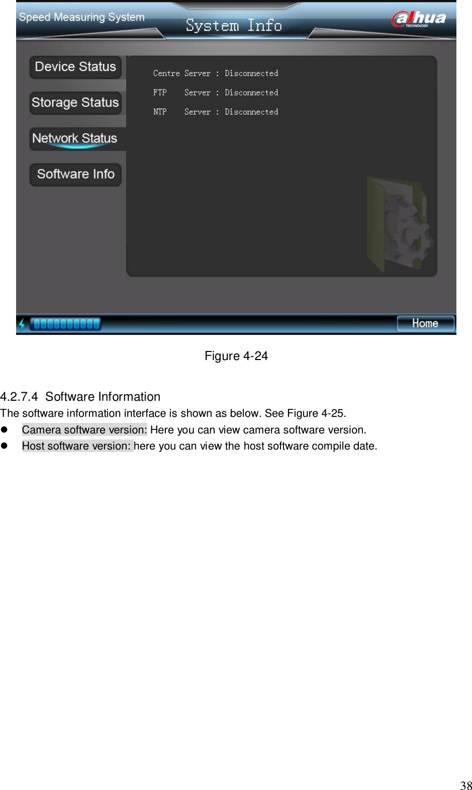
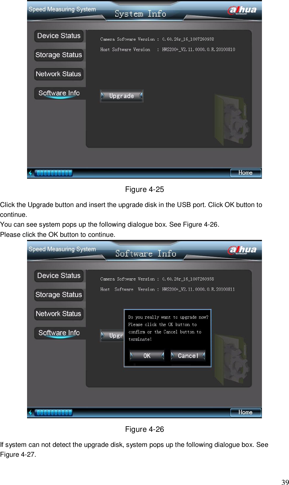
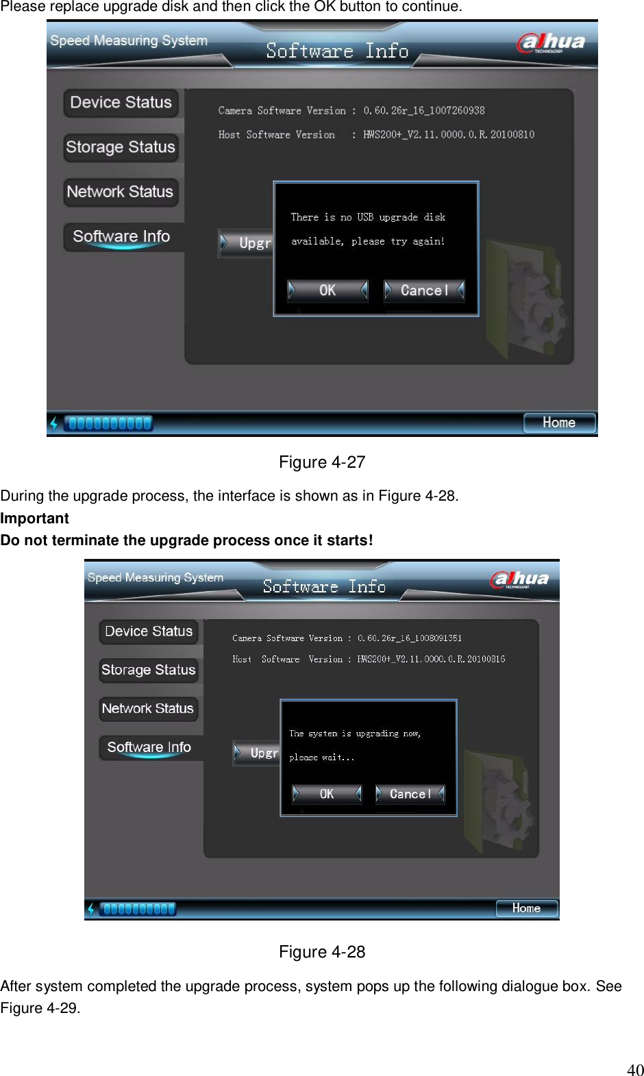
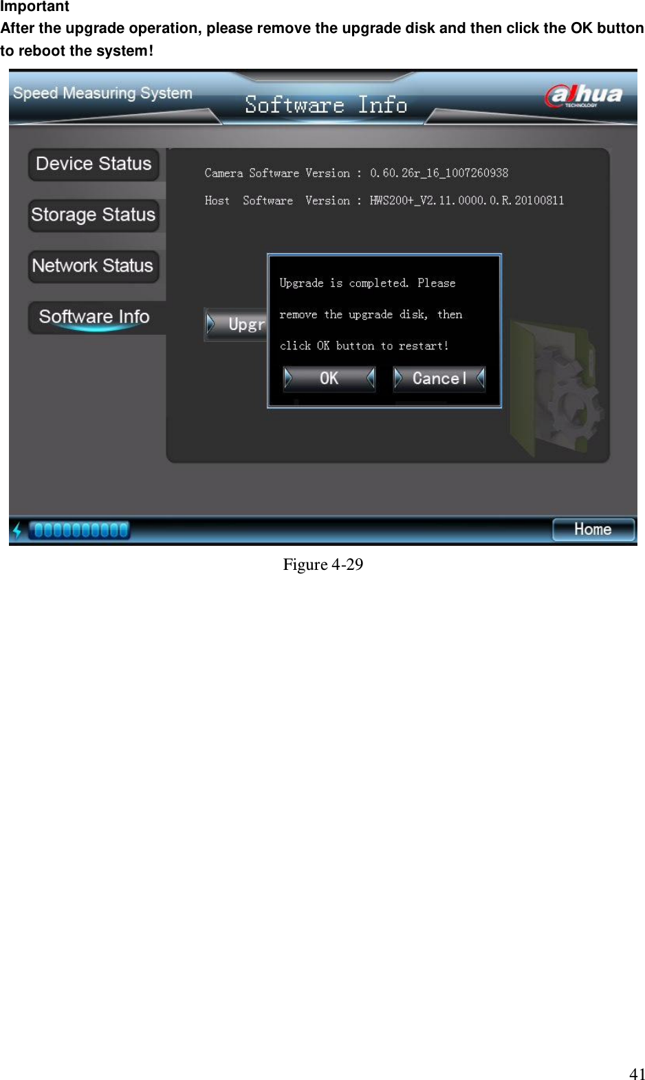
User's Manual
Navigation menu
Upload a User Manual
Namespaces
Wiki Guide
HTML
PDF
Info
Views
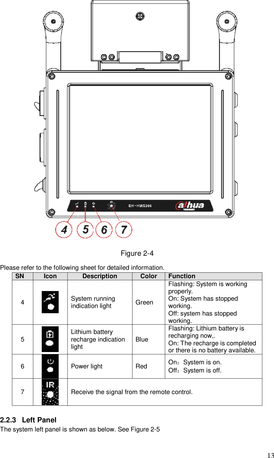
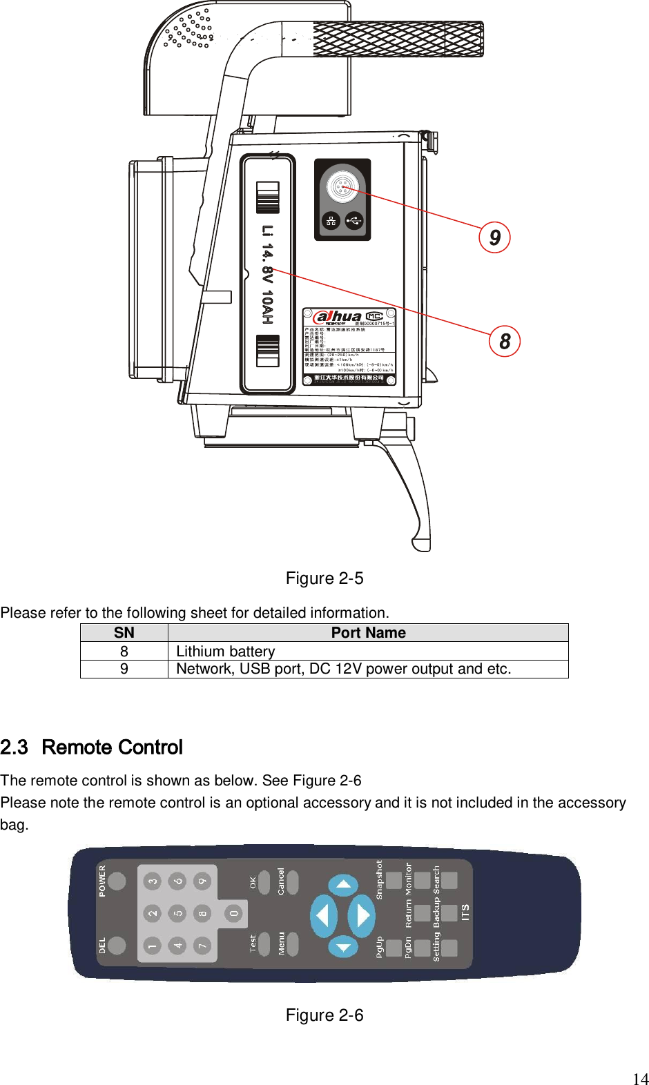
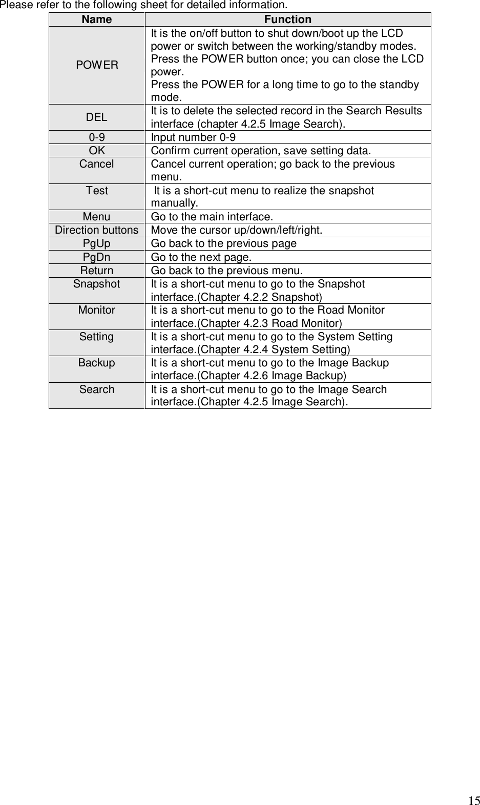
User Manual
Discussion / Help
Navigation