Zhejiang Dahua Vision Technology DH-PFM88 5G Wireless Video Transmission Device CPE User Manual
Zhejiang Dahua Vision Technology Co., Ltd 5G Wireless Video Transmission Device CPE Users Manual
Users Manual

DH-PFM881 User Manual All Right Reserved
5.8GHz Wireless Bridge/CPE/AP
Model: DH-PFM881
User Manual
Version: V1.0.1563

DH-PFM881 User Manual All Right Reserved
Page 1
Contents
Versions .................................................................................................................. 4
References ............................................................................................................. 4
Purpose .................................................................................................................. 4
Notes ...................................................................................................................... 4
Definitions ............................................................................................................. 4
1Product Overview ................................................................................................. 6
1.1Product Advantages ....................................................................................................... 6
1.2Electrical Specifications .................................................................................................. 7
1.3Package Contents ........................................................................................................... 9
1.4Features ............................................................................................................................ 9
1.5Using Example ............................................................................................................... 10
1.6Applications ................................................................................................................... 11
1.7Hardware Overview ...................................................................................................... 12
1.8Understand the DH-PFM881 LEDs ............................................................................. 12
2Installation ........................................................................................................... 13
2.1Connections and installation ....................................................................................... 13
2.2Restore to the Factory Settings ................................................................................... 15
3Quick Configuration ........................................................................................... 15
3.1Log in ............................................................................................................................. 16
3.2Quick Configuration of the Device ............................................................................. 18
4TDMA ................................................................................................................... 20
5Status .................................................................................................................... 21
5.1Status .............................................................................................................................. 22
5.2Monitor .......................................................................................................................... 23
6Wireless ................................................................................................................ 25
7Network ............................................................................................................... 27
7.1Router mode ................................................................................................................. 27
7.2Bridge mode .................................................................................................................. 30
7.3Management ................................................................................................................. 30

DH-PFM881 User Manual All Right Reserved
Page 2
7.4Firewall ........................................................................................................................... 30
7.5IP Aliases ....................................................................................................................... 31
7.6Static Routes ................................................................................................................ 31
7.7Traffic Shaping ............................................................................................................ 31
7.8VLAN Settings .............................................................................................................. 33
8Advanced ............................................................................................................. 34
9System .................................................................................................................. 36
10Tools ..................................................................................................................... 37
11AC Management ............................................................................................ 40
12Logout .................................................................................................................. 41
13Network Configuration Examples .................................................................... 41
13.1AP and Station Network .............................................................................................. 41
13.2WDS Access Point, WDS Station, WDS Repeater Network ...................................... 42
13.3Router Mode ................................................................................................................. 43
Appendix-A Troubleshooting ................................................................................... 44
FIGURE 1 DH-PFM881 USING EXAMPLES..................................................................................................11
FIGURE 2 DH-PFM881 LEDS...................................................................................................................13
FIGURE 3 CONNECTIONS AT BRIDGE MODE.................................................................................................14
FIGURE 4 RESTORE TO THE FACTORY SETTINGS.............................................................................................15
FIGURE 5 LOCAL AREA CONNECTION PROPERTIES.......................................................................................16
FIGURE 6 IP SETTINGS...............................................................................................................................17
FIGURE 7 DH-PFM881 LOG IN INTERFACE.................................................................................................18
FIGURE 8 STATUS PAGE..............................................................................................................................18
FIGURE 9 WIZARD-NETWORK....................................................................................................................19
FIGURE 10 WIZARD-WIRELESS..................................................................................................................20
FIGURE 11 LAST PAGE OF WIZARD.............................................................................................................20
FIGURE 12 TDMA SETTING.......................................................................................................................21
FIGURE 13 STATUS....................................................................................................................................22
FIGURE 14 THROUGHPUT MONITOR...........................................................................................................23
FIGURE 15 ROUTER TABLE.........................................................................................................................23
FIGURE 16 BRIDGE TABLE..........................................................................................................................24
FIGURE 17 ARP TABLE..............................................................................................................................24
FIGURE 18 STA INFORMATION OF AN AP...................................................................................................24
FIGURE 19 AP INFORMATION OF A STATION...............................................................................................25

DH-PFM881 User Manual All Right Reserved
Page 3
FIGURE 20 WIRELESS.................................................................................................................................25
FIGURE 21 CONNECTION FIGURE OF ROUTER MODE....................................................................................28
FIGURE 22 NETWORK ROUTER MODE.........................................................................................................29
FIGURE 23 FIREWALL.................................................................................................................................31
FIGURE 24 TRAFFIC SHAPING SETTINGS......................................................................................................32
FIGURE 25 VLAN.....................................................................................................................................33
FIGURE 26 VLAN SETTING........................................................................................................................34
FIGURE 27 VLAN SCENARIOS...................................................................................................................34
FIGURE 28 ADVANCED..............................................................................................................................35
FIGURE 29 SYSTEM PAGE...........................................................................................................................36
FIGURE 30 TOOLS.....................................................................................................................................38
FIGURE 31 AC MANAGEMENT...................................................................................................................40
FIGURE 32 AP AND STATION NETWORK......................................................................................................41
FIGURE 33 WDS NETWORK......................................................................................................................42
FIGURE 34 ROUTER MODE.........................................................................................................................43
TABLE 1 VERSIONS......................................................................................................................................4
TABLE 2 DEFINITIONS..................................................................................................................................4
TABLE 3 ELECTRICAL SPECIFICATIONS............................................................................................................7
TABLE 4 HARDWARE INFORMATION............................................................................................................12
TABLE 5 LED INFORMATION....................................................................................................................13
TABLE 6 MAIN PARAMETERS AT THE FACTORY SETTINGS................................................................................15
TABLE 7 CONFIGURATIONS SHOWN IN STATUS...........................................................................................22

DH-PFM881 User Manual All Right Reserved
Page 4
Versions
Table 1 Versions
Version Date History Author
1.1 2015-07-24 Created Gao Feng
1.2 2015-11-04
Update pictures and partial
functions description.
Based on r1563.
Liu Meng
1.0.1563 2016-01-04 Update some functions parameters Liu Meng
References
Purpose
This document is proposed for the users of DH-PFM881 devices, helping them to
configure the device and list the troubleshooting, so that the devices can be used
successfully quickly.
This document mainly contains the following parts: hardware information, web
configuration menu descriptions, network configuration examples, and
troubleshooting. It can help the customers quickly be familiar with the devices and
use them correctly.
Notes
This document is to characterize the DH-PFM881 series of devices. Please read the
document carefully before setting up device. Any damage which is caused by
inappropriate use will not be covered under the warranty.
Definitions
Table 2 Definitions
No. Items Description
1 DH-PFM881 Outdoor, long distance AP/CPE/Bridge devices
2 XTrans
XTrans is a series of wireless technologies,
including TDMA, 5M/10M/20M/40MHz bandwidth
support, intelligent rate control, Auto ACK
Time-out adjust, having the advantage of long

DH-PFM881 User Manual All Right Reserved
Page 5
No. Items Description
transmission range, high date rate and robust
transmission.
3 AP Access Point
4 Station(Client)
WIFI station that can be associated to an access
point.
5 CPE
Customer-premises equipment: it is
any terminal and associated equipment located at
a subscriber's premises and connected with
a carrier's telecommunication channel at
the demarcation point.

DH-PFM881 User Manual All Right Reserved
Page 6
1 Product Overview
DH-PFM881 is a powerful WIFI Bridge/AP/CPE device, which allows WIFI access
and video/audio/data transmission device, enables long-range, fast speed and
robust wireless connections. Integrated with the XTrans technology, DH-PFM881
has the advantages of long-distance, high-throughput, and Strong
anti-interference.
XTrans technologies include TDMA, 5M/10M/20M/40MHz bandwidth, intelligent
rate control, Auto ACK Time-Out Adjust and so on. TDMA technology solves the
problems of hidden-node problem in the 802.11 network. 5M/10M/20M/40MHz
bandwidth can be flexibly configured by the uses in different working scenario to
achieve the best link quality. Intelligent rate control algorithm can be adapted to
quick channel quality variations automatically, thus stabilizing the wireless
throughput. ACK Time-Out Auto Adjust can automatically detect the distances of
the DH-PFM881 devices, and thus adjust the wireless parameters to achieve the
best wireless link quality.
The best transmission range and max speed of DH-PFM881 can be as high as
15Km and 300Mbps, making it suitable for many applications of WIFI Bridge/CPE,
especially have advantages for point-to-multi-point communication.
1.1 Product Advantages
The DH-PFM881 has the industrial leading technology, owing the performance
capability of a wireless base station with only a small form factor, furthermore, it
has very attractive low cost.
DH-PFM881 has the following advantages compared to the competitors:
1. Embedded TDMA technology
DH-PFM881 devices is embedded with TDMA technology, including TDMA,
5/10/20/40MHz bandwidth, intelligent rate control, Auto ACK Time-out adjust.
They make the device have longer transmission distance, higher throughput and
better point-to-multi-point performance.
2. Longer transmission distance, higher throughput
The longest transmission distance of DH-PFM881 can be as far as 15 km, and the
max throughput can be 300Mbps. It can satisfy the needs of most of the
applications.

DH-PFM881 User Manual All Right Reserved
Page 7
3. Embedded hardware watchdog
DH-PFM881 is embedded with hardware watchdog, which is used to monitor the
working status of the device. Once the system is not working properly, the
DH-PFM881 device can be rebooted to guarantee the stability of the system.
4. Software Ping watchdog function
DH-PFM881 software ping watchdog function enable the device periodically ping
another device associated to, so that it can detect if the system is working well. If
the wireless link is lost or there is any problem, the device is rebooted. This is
important because the devices can be restored to work automatically if there is
any problem, and avoid the extra human labour to maintain the outdoor devices.
5. More Non-standard channels availability
Currently most of the WIFI devices are working at standard 802.11 5.8GHz
frequency. However, standard 802.11 5.8GHz only provide limited channels, and
there is serious interference if there are a lot of 5.8G WIFI devices nearby.
DH-PFM881 support more channels near 5.8GHz band, and spread the band to
non-standard frequency part: 4920MHz-6100MHz。The advantage of working at
the non-standard band is to avoid the interference in the standard channels, and
the wireless throughput can be improved.
Note: Please confirm whether those non-standard channels are permitted locally
before using them.
6. Outdoor industrial product
DH-PFM881 device can work at all kinds of outdoor severe environments,
including -30 to 70 degree temperature, 5% to 95% humidity, while maintain good
performance.
1.2 Electrical Specifications
The electrical specifications are shown are the following table:
Table 3 Electrical Specifications
Items Specifications

DH-PFM881 User Manual All Right Reserved
Page 8
W
I
R
E
L
E
S
S
Standard IEEE802.11 a/n(2T2R 300Mbps)
Operation
Frequency
5.745~5.825 GHz(More Non-standard channels is
availability,4920MHz-6100MHz)
Modulation
Mode 802.11 a/n: OFDM
Antenna 15dBi Gain
Output power +24dBm(@6.5Mbps,11a), +23dBm(@300Mbps,11n)
Receive
Sensitivity -72dBm @ 65Mbps, -94dBm@6Mbps
Date rate
11n:13.5/15/27/30/40.5/45/54/60/81/90/108/120/121.5/135/
150/162/180/216/240/270/300Mbps(40MHz Channel Width)
11n:130/117/104/78/65/58.5/52/39/26/13/6.5Mbps(20MHz
Channel Width)
:11a 54/48/36/24/18/12/9/6Mbps(adaptive)
Distance Outdoor open area: <15 km
H
A
R
D
W
A
R
E
Power supply 24V POE
Interface POE
LED WIFI Status/LAN/Power/Signal strength
Operation
Temperature -30℃~+70℃
Storage
Temperature -40℃~+85℃
Operation
Humidity 5~%95%RH
Device Size 280*80*30(mm)
S
O
F
T
W
A
R
E
Encryption 802.1x/WPA-PSK/WPA2-PSK
Network Router/Bridge
Operation
Mode
Access Point/Station/WDS Access Point /WDS Station/WDS
Repeater
Security MAC filter, SSID hidden
Network
protocol TCP/UDP/ARP/ICMP/DHCP/HTTP/NTP
TDMA Supported (Avoid 802.11 hidden-node problems, and
improve the point-to-multi-point performance)
Auto ACK
timing Adjust Supported
Management NTP, SNMP, Syslog, Telnet

DH-PFM881 User Manual All Right Reserved
Page 9
and Logs
Web based
Configuration Supported
Firmware
Update Supported
Bandwidth
supported 5M/10M/20M/40MHz
1.3 Package Contents
Open the package carefully, and make sure that none of the following items listed
are missing:
y One DH-PFM881 device
y One 24V/0.5A POE power adapter
y DH-PFM881 Mast-Mount Strap Special Screw Set
1.4 Features
y High performance 802.11n 2×2 MIMO chip
y Best transmission range: 15Km, and max transmission throughput:
300Mbps
y Integrated XTrans technology, including TDMA, intelligent rate control,
Auto ACK Time-out adjust
y TDMA solves the problems of hidden-node problem in the 802.11
network, thus having better long-distance and PTMP performance
y Support 5 operation mode: Access Point, Station, WDS Access Point, WDS
Station, WDS Repeater
y Support point-to-point, point-to-multipoint connection
y Unique RF and antenna design enables long-range transmission

DH-PFM881 User Manual All Right Reserved
Page 10
y Wireless multimedia optimization technology guarantees video/audio
transmission QoS
y Web based working scenario selection makes the installation and setting
much easier
y Reliable POE power supply, support 802.3af standard
y Web-based configuration, easy to use
y Waterproof housing and accessory kit protects
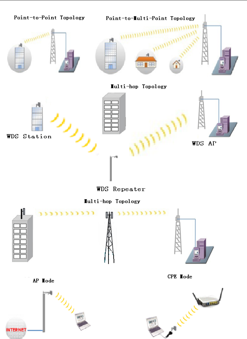
1.5 Using Example
The DH-PFM881 usage example are shown in Figure 1, it can be used as WIFI AP,
CPE, or outdoor PTP, PTMP topology. Therefore, DH-PFM881 is suitable for
various applications like wireless video transmission, and wireless signal coverage.
DH-PFM881 User Manual All Right Reserved
Page 11
Figure 1 DH-PFM881 using examples
1.6 Applications
DH-PFM881 can be used widely in the following applications:

DH-PFM881 User Manual All Right Reserved
Page 12
y Wireless video surveillance (free-way, city, police, oil pipeline, forest and
etc.)
y Carrier wireless backhaul and rural area internet last-mile wireless solution
y Enterprise local area network inter-connection
y WIFI signal coverage and rural wireless coverage
1.7 Hardware Overview
DH-PFM881’s hardware information is described in the following Table 4:
Table 4 Hardware information
Hardware Specifications
CPU/Baseband Radio Atheros AR9344
Memory 64MB DRAM, 8MB Flash
Physical Interface 2×10/100M Base-TX (Cat. 5/5E, RJ-45)
Ports
LED Status Power, LAN, WLAN, 3×Link Quality
Power supply POE, Power Adapter 24V/0.5A
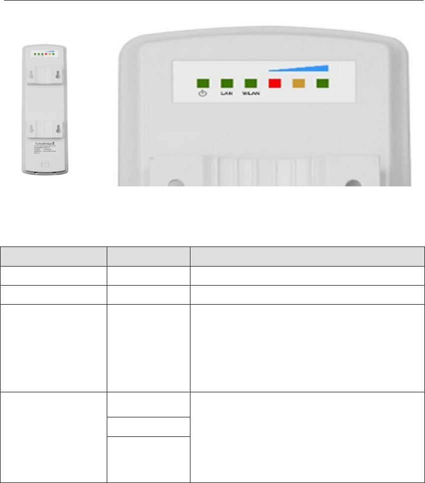
1.8 Understand the DH-PFM881 LEDs
The LEDs of DH-PFM881 can be divided to 2 groups. One group of LEDs are
Indicators, including the left 3 LEDs of Figure 2, and they are Power, LAN and
WAN indicators. The other group of LEDs are Link Quality, including the right 3
LEDs of Figure 2, shown the signal strength.
DH-PFM881 User Manual All Right Reserved
Page 13
Figure 2 DH-PFM881 LEDs
Table 5 LED Information
LED Color Status
POWER Green ON = Device Power on
LAN Green ON = Device connected to the network
WLAN Green
OFF = Device radio is OFF
ON = Device radio is ON, but not sending
or receiving date through the wireless LAN.
BLINK= Device radio is ON, and sending or
receiving date through the wireless LAN.
Link Quality
Red Showing the signal strength between the
device and the network.
Green is ON = good quality
Yellow is ON = medium quality
Red = poor quality or no link
Yellow
Green
2 Installation
This chapter describes how to install DH-PFM881 device in the bridge mode, and
the installation method of router mode can be seen in Chapter 7.
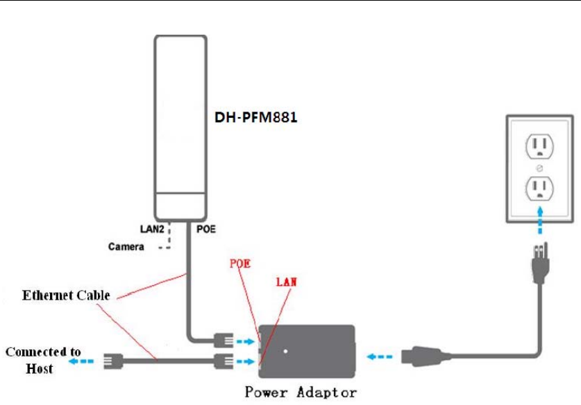
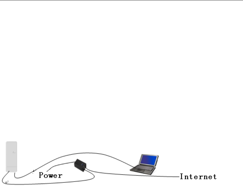
2.1 Connections and installation
The connection of DH-PFM881 device to POE and power supply is shown in Figure
3.
DH-PFM881 User Manual All Right Reserved
Page 14
Figure 3 Connections at Bridge mode
DH-PFM881 has 2 RJ45 ports, and they are marked with “POE” and “LAN2”
separately. In the bridge mode, please connect the device with the POE power
adaptor in the following way:
1) Remove the bottom cover from the DH-PFM881 device, and you will see
there are 2 RJ45 ports marked with “POE” and “LAN2”.
2) Using an Ethernet cable to connect the POE power adaptor and the “POE”
port of the DH-PFM881 device.
3) Connect the POE adaptor to the normal power supply board.
4) Normally, “LAN2” port of the DH-PFM881 can be connected to IP Camera
and other devices, or leave it unconnected
5) Mount the DH-PFM881 securely to the pole by locking the strap tightly.
DH-PFM881 User Manual All Right Reserved
Page 15
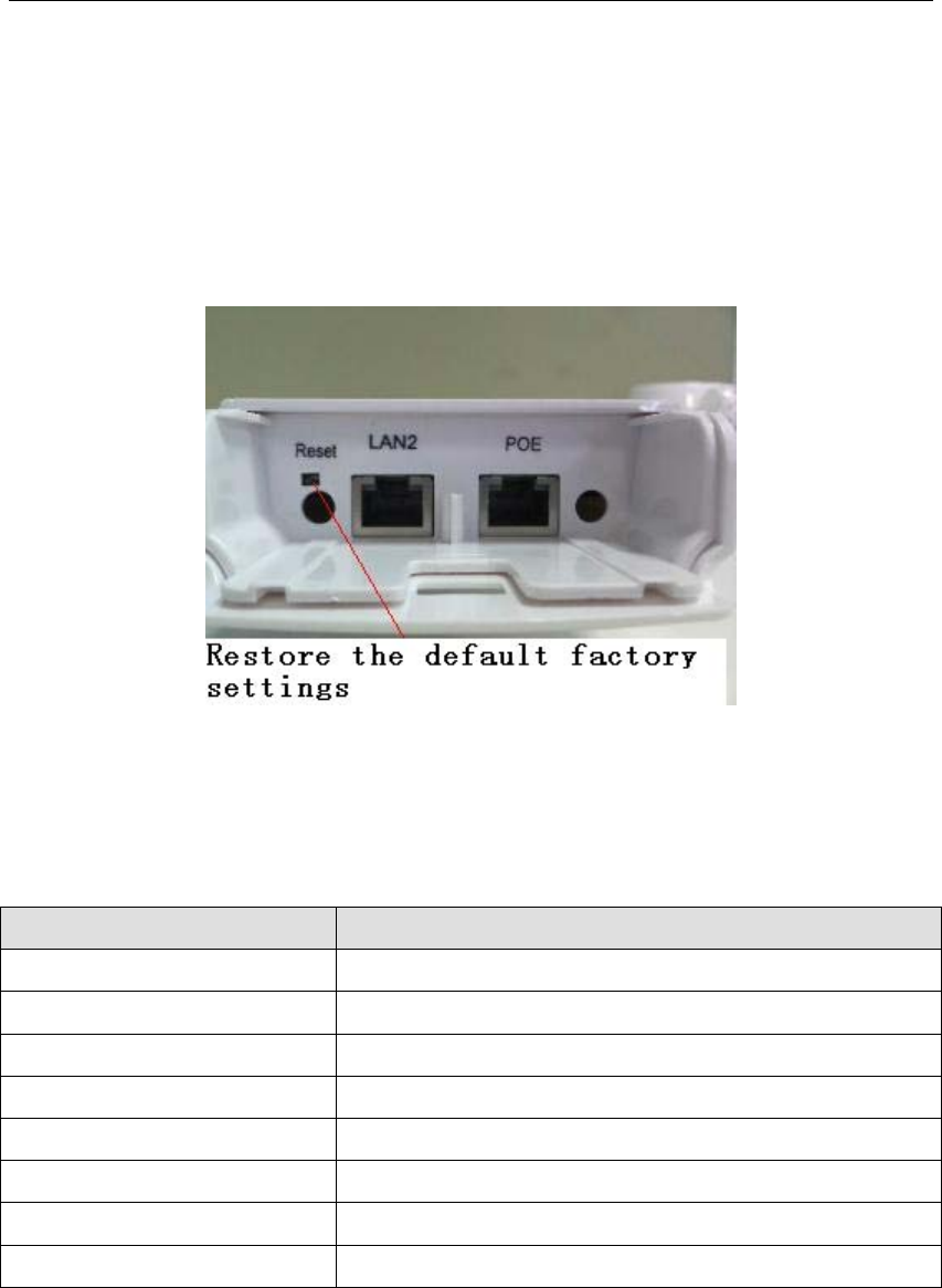
2.2 Restore to the Factory Settings
In some cases, uses can restore the device to the factory settings by the following
way in the Figure 4. Push the reset button for 5~10 seconds until all LED is on. This
will restore to the factory setting. During this process, the DH-PFM881’s RJ45 ports
will be connected and disconnected twice.
Figure 4 Restore to the factory settings
For default, all the factory settings are shown in the following Table 6.
Table 6 Main parameters at the factory settings
Items Default Settings
IP address 192.168.1.36
User name admin
Password admin
Wireless mode Station
SSID DaHua
Output power High(24dBm)
Encryption WPA->WPA2->CCMP- :>Password 1234567890abc
Network mode Bridge
3 Quick Configuration
This chapter describe how to configure the device quickly.
DH-PFM881 User Manual All Right Reserved
Page 16
3.1 Log in
To log in the DH-PFM881 device, user needs to configure the TCP/IP of your
computer first as the following steps:
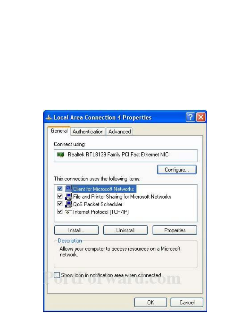
1、Right click Local Area Connection icon of your computer and click properties,
then click Continue, the Local Area Connection Properties dialog box appears as
Figure 5.
Figure 5 Local Area Connection Properties
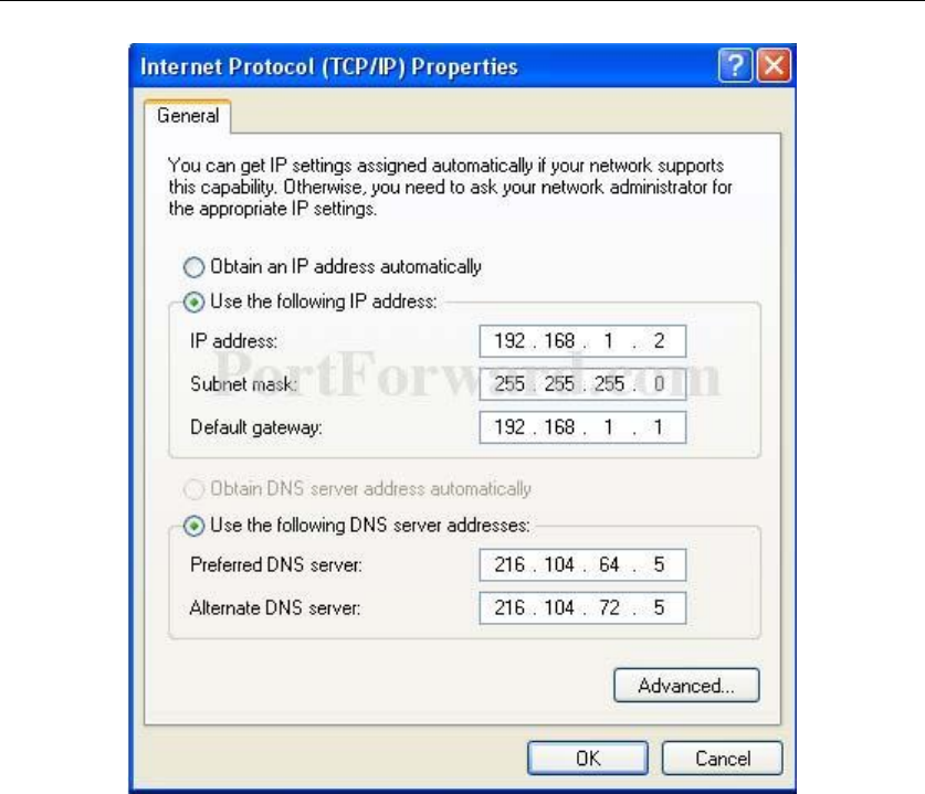
2、Select Internet Protocol (TCP/IP) and click Properties button, and the following
dialog box appears:
DH-PFM881 User Manual All Right Reserved
Page 17
Figure 6 IP settings
3、In the above Figure 6, IP address should be set to 192.168.1.*, here * can be a
number between 1-255 (but not 36) since the DH-PFM881 default IP address is
192.168.1.36.
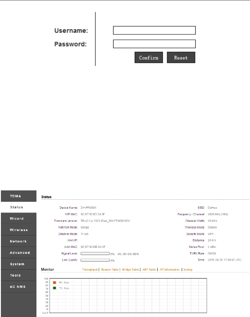
4、When the above IP setting is done, input the default IP 192.168.1.36 into the
address bar of your web browser, and the following log in interface appears as
shown in Figure 7.
5、In Figure 7, input the user name and password (default is admin/admin) and
click the Confirm button, then you can log in to the web configuration menu of
the DH-PFM881 device.
DH-PFM881 User Manual All Right Reserved
Page 18
Figure 7 DH-PFM881 Log in interface
3.2 Quick Configuration of the Device
The users will see how to configure the DH-PFM881 device quickly in this chapter.
1、 The first page shown after log in is the Status page, which indicates the
working status, current setting, software version and other information of the
DH-PFM881 device. User can switch to other pages by clicking the left main
menus in Figure 8.
Figure 8 Status Page
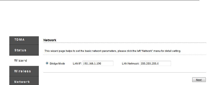
2、Click Wizard main menu, the users can configure the device quickly, including
Network and Wireless settings and so on. It is Wizard-Network page as shown
in Figure 9, and this page helps to set the basic network parameters. The default
mode is Bridge mode, and the default LAN IP address is 192.168.1.36. If the user
wants to configure the device to Router mode, please click Network in the main
menu.
DH-PFM881 User Manual All Right Reserved
Page 19
Note: If several DH-PFM881 devices are connected in the Point-to-Point or
Point-to-Multi-Point topologies, they must be configured to different IP address
to avoid collisions.
Figure 9 Wizard-Network
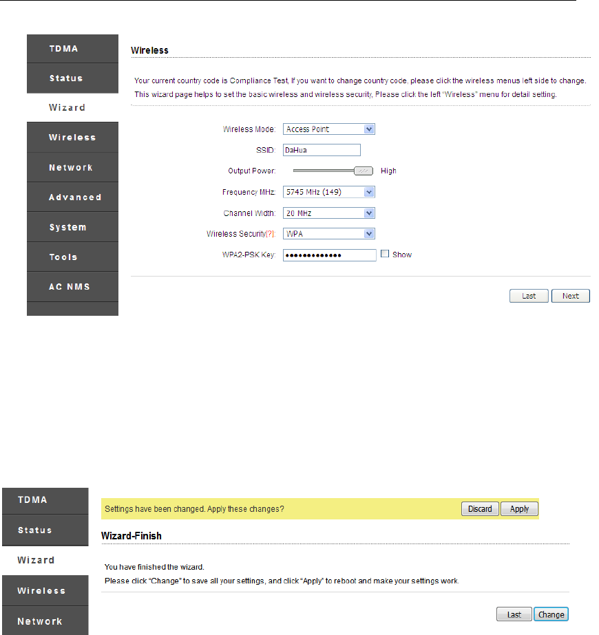
3、After finishing the Wizard-Network settings, click next and it goes to
Wizard-Wireless page shown in Figure 10. The most used wireless mode is the
Access Point and the Station.
Station mode:The device acts as a WIFI station, and it can be connected to a
normal home access point or DH-PFM881 access point.
Access Point mode:The DH-PFM881 device acts as an access point, which allows
normal WIFI stations access. For detail settings of wireless mode, please click
Wireless in the main menu.
Note: If two DH-PFM881 devices need to be connected in point-to-point
topology, one of the device need to be configured as Access Point, and the other
one need to be configured as Station, and both of them should have the same
Encryption method.
DH-PFM881 User Manual All Right Reserved
Page 20
Figure 10 Wizard-Wireless
4、The last page of Wizard is shown in Figure 11. User can click Change to save all
the settings, and then click Apply the make the setting effective, or click Last to
modify the previous settings.
Figure 11 Last Page of Wizard
4 TDMA
Currently, most of the outdoor bridge products are developed based on 802.11
protocols, however, it has the limitations of short-distance, hidden node problems,
and poor point-to-multi-point performance.
TDMA technologies, developed and patented by , utilizing a series of advanced
technologies such as TDMA, 5M/10M/20M/40MHz bandwidth support, intelligent
rate control, Auto ACK Time-out Adjust, having the advantage of long
transmission range, high date rate and robust transmission.
DH-PFM881 User Manual All Right Reserved
Page 21
TDMA technology solves the problems of hidden-node problem in the 802.11
network infra-structure. 5M/10M/20M/40MHz bandwidth can be flexibly
configured by the uses in different working scenario to achieve the best link
quality. Intelligent rate control algorithm can be adapted to quick channel quality
variations, while stabilize the wireless throughput, thus suitable for long-distance
transmission. ACK Time-out Auto Adjust can automatically detect the distances of
the DH-PFM881 devices, and adjust the wireless parameters to achieve the best
link quality.
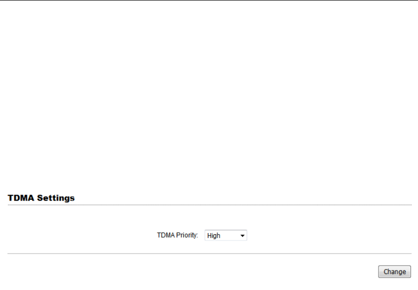
The TDMA setting is shown in the following Figure 12.
Figure 12 TDMA setting
To use the TDMA, the user needs to enable TDMA mode in the AP device, and set
a priority level in the station device. When several stations are connected to one
AP, different stations demand different throughput. If the station demands higher
throughput, its priority level can be set to High, otherwise set to Low. When the
stations demand the same throughput, their priority level can be set to the same
level.
Note: When using TDMA mode, the TDMA button need to be enabled at both AP
and station devices in the web-based configuration menu. The devices from other
vendors cannot be connected to DH-PFM881 in the TDMA mode.
5 Status
Status is the first page shown after logging in. It shows the current configuration
and real-time monitoring of the device, seen in the following Figure 13. This page
is divided into 2 parts: Status and Monitor.

DH-PFM881 User Manual All Right Reserved
Page 22
Figure 13 Status
5.1 Status
All the configurations in Status page is shown in Table 7.
Table 7 Configurations shown in Status
Items Description Items Description
Device Name of the
device , for
example:
DH-PFM881
SSID The name of the wireless
network
WIFI MAC MAC of the wireless
port
Frequency/
Channel
Wireless channel chosen
Firmware
Version
Software version
number
Channel
Width
5MHz, 10MHz, 20MHz,
40- MHz, 40+ MHz
Network Mode Network mode:
Router or Bridge
Wireless
Mode
Access Point, Station WDS
Access Point, WDS
Station, WDS repeater
Channel Mode 11 a/n Security
Mode
Wireless encryption
method
WAN IP WAN IP address Distance The distance between two
associated devices
WAN MAC MAC of the WAN
port
Noise Floor Noise Floor value
Signal Level It indicates the
signal strength of
TX/RX Rate The date rate of current
device during sending
DH-PFM881 User Manual All Right Reserved
Page 23
the device and receiving data.
Link Quality Quality of the
connection link
Time The real-time
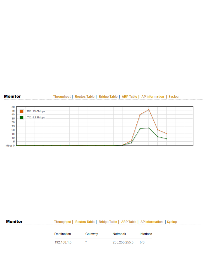
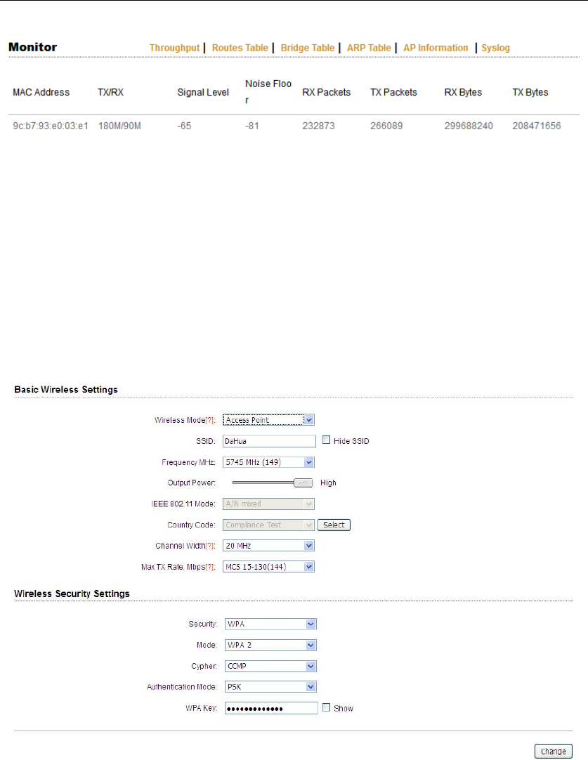
5.2 Monitor
Throughput:The figure here monitors the real-time throughput of the wireless
link, shown in the following Figure 14.
Figure 14 Throughput monitor
Route Table:It is stored in a router that lists the routes to particular network
destinations, and in some cases, metrics (distances) associated with those routes.
The route table contains information about the topology of the network
immediately around it.
Figure 15 Router Table
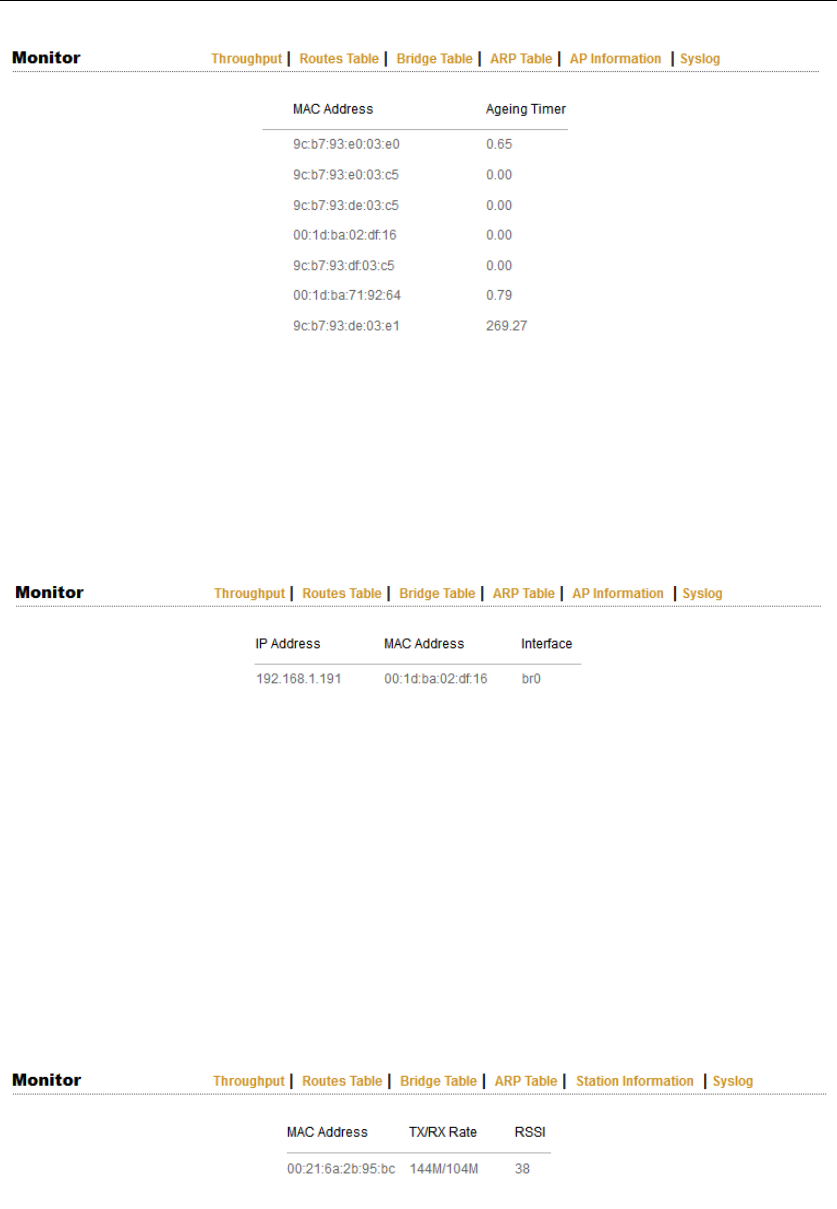
Bridge Table:It lists all the devices that communicate through the DH-PFM881
device.
DH-PFM881 User Manual All Right Reserved
Page 24
Figure 16 Bridge Table
ARP Table :It lists the IP address and MAC address of the devices that
communicate through the LAN port of the DH-PFM881 device.
Figure 17 ARP Table
AP/Station Information: Showing the status information of the associated
devices.
For example, if the DH-PFM881 device is an AP, and the associated device is a
Station, and this Station Information shows the related information of the Station
device in the Figure 18.
Figure 18 STA Information of an AP
If the DH-PFM881 is a Station, and AP Information shows the associated AP
device’s information, seen in Figure 19.
DH-PFM881 User Manual All Right Reserved
Page 25
Figure 19 AP Information of a Station
Syslog:Display the log information of DH-PFM881.
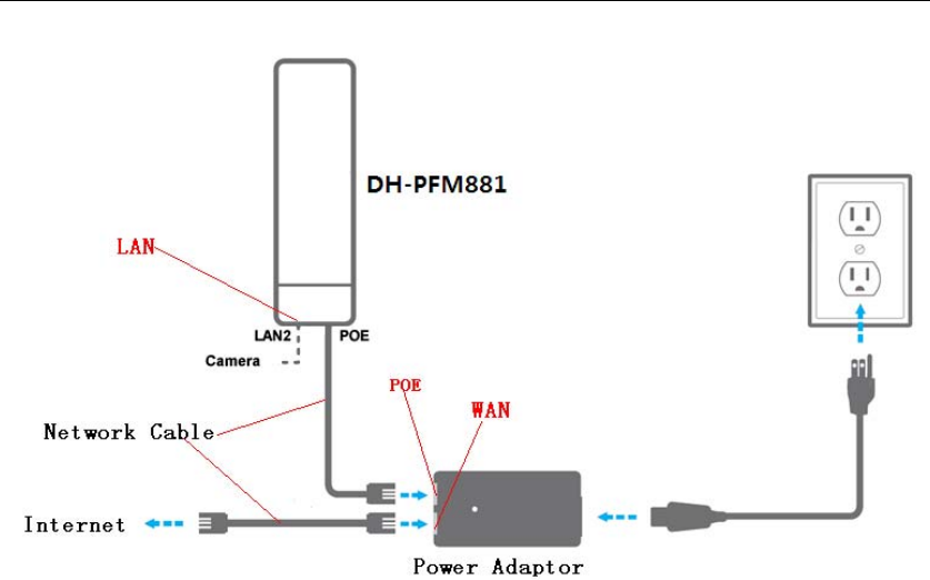
6 Wireless
Wireless is shown in Figure 20.
Figure 20 Wireless
Wireless Mode: There are totally 5 wireless modes, including: Station, Access
Point, WDS Station, WDS Access Point, and WDS Repeater.
Access Point: Access point.
Station: A client device that can be connected to an AP.

DH-PFM881 User Manual All Right Reserved
Page 26
WDS Station: Use WDS feature to link multiple APs in a network, all associated
stations from any AP can communicate with each other like in ad-hoc mode. WDS
station means this device is a station in WDS mode.
WDS Access Point: Use WDS feature to link multiple APs in a network, all
associated stations from any AP can communicate with each other like in ad-hoc
mode. WDS AP means this device is an AP in WDS mode.
WDS Repeater:A DH-PFM881 device can be configured to WDS Repeater mode,
so that it can connected to another WDS Station or WDS Repeater.
SSID: Name of a wireless.
Shown in Figure 21, the user can click the Select button to list all the SSIDs that
can be associated, and then choose the one need to be associated.
Frequency:This only appears when the device is configured to Access Point mode
or WDS Access Point mode. The device can only work on one channel at the same
time.
Frequency scan list:This only appears when the device is configured to Station
mode or WDS Station mode. If it’s not enabled, the station will scan all the
channels which both the device and the country code allowed and then choose
the same channel as the associated AP. If it’s enabled, click select, another window
will pop up and let the user to choose the working channels, and the channels
should include the associated AP’s channel, which can fasten the association
process between the AP and the Station.
Output Power:Output power of the DH-PFM881 device.
Country Code:Different countries allows different channels, use can choose the
country code to only allow the device works at the channels permitted in the
particular country.
Channel Width:Channel width selection, and DH-PFM881 device supports
5MHz/10MHz/20MHz/40MHz bandwidth.

DH-PFM881 User Manual All Right Reserved
Page 27
Max TX Rate:Max transmission rate, and it can be used to limit the max
transmission rate of a device.
Root AP MAC Address:In Station, WDS Station, and WDS Repeater modes, users
can use this to limit the APs associated to.
Security:User can set the security based on needs to guarantee the wireless
security.
WPA:Encryption method supported by 802.11 Protocol.
7 Network
7.1 Router mode
DH-PFM881 acts as a router when configured to Router mode. In router mode, the
connection is shown in Figure 21. User needs to connect the POE port of POE
adaptor to the POE port of the DH-PFM881.
After the above connection, the DH-PFM881 can work as a router. The LAN2 port
of DH-PFM881 device acts as the LAN port of the router, and LAN port of POE
adaptor acts as the WAN port of the router.
DH-PFM881 User Manual All Right Reserved
Page 28
Figure 21 Connection figure of router mode
The Network page is shown in Figure 22.
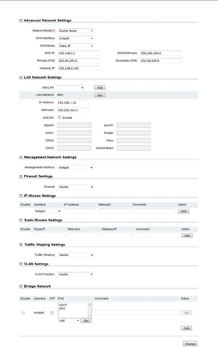
DH-PFM881 User Manual All Right Reserved
Page 29
Figure 22 Network Router mode

DH-PFM881 User Manual All Right Reserved
Page 30
WAN Mode:WAN mode can be configured to DHCP/PPPoE/Static IP. When set
to DHCP, the device can dynamically get the IP address; otherwise, user needs to
manually set the IP address, Netmask, gateway and other information.
WAN IP:WAN IP address. It should be set to the same segment of IP address of
the internet provided by ISP, please check with the ISP for this information.
WAN Netmask:WAN Netmask, use can check with the ISP for this information.
Note: WAN IP address should not be the same as the IP devices of the internet to
avoid collision.
Primary DNS and Secondary DNS: Please check with the ISP for the information.
Gateway IP:The IP address of WAN gateway.
7.2 Bridge mode
In Bridge mode, there is no WAN port. The LAN port of the POE adaptor, and the
LAN2 port of the DH-PFM881 device can all be the LAN port, and the user can
choose one of them to use as LAN port. Please refer to Figure 3 for the
connections in Bridge mode, and the IP address/Netmask information setting is
the same as Router mode.
7.3 Management
The IP address of the device can be modified, and the management of the device
can be performed by setting the specified management interface.
7.4 Firewall
When the firewall is enabled, the device can allow only some devices to be
associated to. Shown in Figure 23, and there are 4 cases of Firewall filtering.
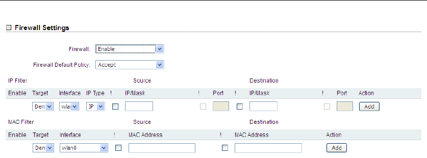
DH-PFM881 User Manual All Right Reserved
Page 31
Figure 23 Firewall
1. Accept one or several devices with particular MAC address.
2. Deny one or several devices with particular MAC address.
3. Accept one or several devices with particular IP address.
4. Deny one or several devices with particular IP address.
7.5 IP Aliases
Add multiple IP to a network interface.
7.6 Static Routes
This feature can be set to static routing.
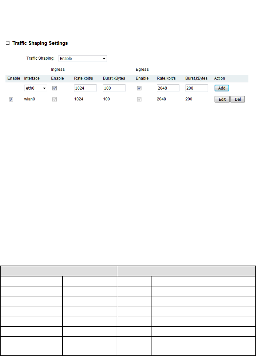
7.7 Traffic Shaping
Traffic shaping is used to control the traffic of ingress/egress based on each
network port. As show below, the ingress of wlan0 is limited to 1024Kbps, and the
egress is limited to 2048Kbps. That means the receiving rate of the wireless link is
limited within 1Mbps, the sending rate is limited to less than 2Mbps. But usually,
the input limited effect is not obviously, that’s because we could not control how
quickly the traffic arrives. However, when a port sends out egress traffic, it can
control how quickly the traffic exits.
DH-PFM881 User Manual All Right Reserved
Page 32
Burst defines the how many bytes allowed for downloading/uploading during a
quick time. That leads to momentary throughput can greater than the limit value.
Figure 24 Traffic Shaping Settings
z Ingress traffic entering wlan0, control the input rate
z Egress traffic exiting wlan0, control the output rate
The relationship of rate and burst for ingress:
z Set burst to 0, the rate of ingress is unlimited
z Set burst to about 1/10 of rate limit, the rate curve is stable
z Set burst larger than rate limit, the rate curve will hold a high value for a while then
down to stable
Below is the table that reflects the relationship between ingress rate limit and
burst.
Ingress Throughput when reach stable
RateLimit(kbps) Burst(Kbytes) (Mbps) Description
10000 0 29.587 Unlimited
10000 10 4.286 Stable
10000 100 8.037 Oblique up to stable
10000 1000 8.825 From 9.5 down to stable
10000 10000 8.6 From 28.5 down to stable
10000 40000 8.6 Hold on 10 seconds at 29.6, then
suddenly down to stable
The relationship of rate and burst for egress:
z Set burst less than 1/10 of rate limit, the rate curve is stable totally
z Set burst larger than rate limit, the rate curve will hold a while at a higher value then
down to stable
DH-PFM881 User Manual All Right Reserved
Page 33
Below is the table that reflects the relationship between egress rate limit and burst.
Egress Throughput when reach stable
RateLimit(kbps) Burst(Kbytes) (Mbps) Description
20000 0 18.853 Stable
20000 20 19.021 Stable
20000 200 19.205 Stable
20000 2000 19.437 From 23.5 down to stable
20000 20000 19.2 Hold on 20 seconds at 24.5, then
suddenly down to stable
20000 80000 19.2 Hold on several minutes at 24.5,
then suddenly down to stable
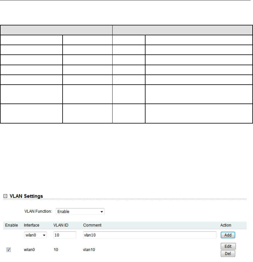
7.8 VLAN Settings
The VLAN function allows user to create multiple virtual local area network. As
show below, we add a VLAN on port wlan0. The VLAN ID is 10. The range of VLAN
ID is 2~4094. Each VLAN ID represents a different VLAN.
Figure 25 VLAN
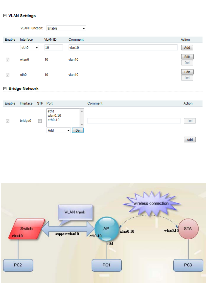
Bridge function is needed to use together with VLAN. As show below, we add
VLAN 10 on port eth0 and wlan0, they are eth0.10 and wlan0.10, and put them
into the same bridge. The packets from eth0.10 or wlan0.10 will be added a VLAN
label which ID is 10. That requires: the opposite wireless connection side must
support VLAN 10, the device which connects with eth0 is also need to support
VLAN 10.
DH-PFM881 User Manual All Right Reserved
Page 34
Figure 26 VLAN Setting
Below is a common usage:
Figure 27 VLAN Scenarios
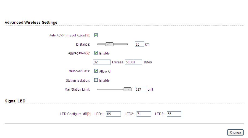
8 Advanced
The Advanced page is shown in Figure 28.
DH-PFM881 User Manual All Right Reserved
Page 35
Figure 28 Advanced
Auto ACK-Timeout Adjust:It is suggested to enable this function, so that the
distance between 2 DH-PFM881 devices can be detected and all the related
parameters can be optimized to achieve the best link quality.
Distance: The distance can be set manually if the Auto ACK-Timeout Adjust is
disabled, otherwise, the distance parameter is not allowed to be set. It is
suggested the distance is set automatically by enabling Auto ACK-Timeout Adjust
parameter.
Aggregation: It enables several data frames of 802.11 to be aggregated and
transmitted out, thus improve the throughput. In default, it’s enabled.
Multicast Data: When it’s enabled, DH-PFM881 devices allow multicast
function.
Station Isolation:Enable this feature can make connection to with an access
point, the WDS access points, WDS repeater equipment cannot communicate with
each other, even though the client IP duplicate nor of communication have any
impact.
Max Station Limit: By setting it to limit the number of clients and WDS clients
that are connected to an access point, a WDS access point, a WDS repeater.
DH-PFM881 User Manual All Right Reserved
Page 36
LED configure:This is to configure the signal strength value needed to light on.
There are 3 LEDs on DH-PFM881 devices (LED3 value > LED2 value > LED1 value).
The default values are -86dBm, -71dBm and -56dBm. When LED1 value < signal
strength < LED2 value, LED1 is lighted on; When LED2 value < signal strength <
LED3 value, both the LED1 and LED2 are lighted on; When signal strength > LED3
value, all three LEDs are lighted on.
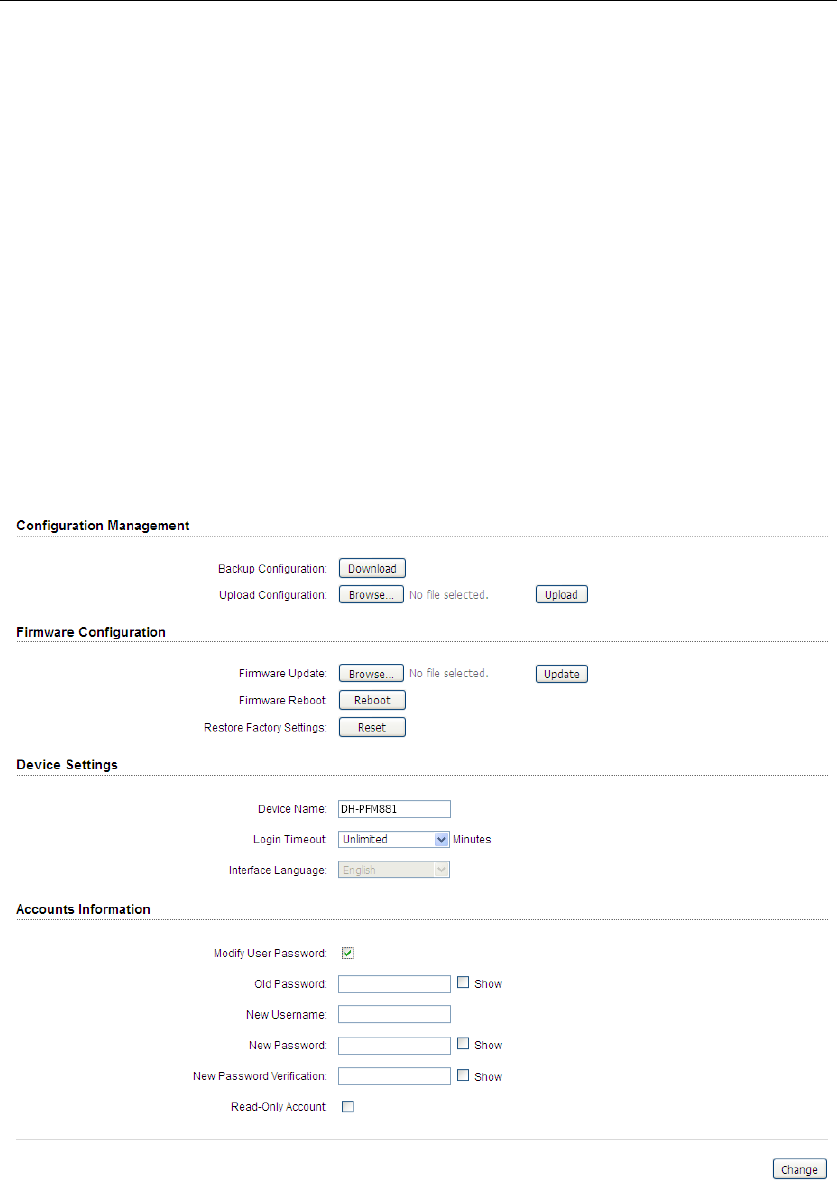
9 System
System page is shown in Figure 29, and it is divided into the following 4 parts:
Configuration, Firmware, Device Setting, Accounts.
Figure 29 System Page
Backup configuration :When clicking Download button, the current
configuration can be backed up to a file.

DH-PFM881 User Manual All Right Reserved
Page 37
Upload configuration:When clicking browse, user can choose the backup
configuration file and then click upload, so that the configuration stored in the
backup file can be applied.
Firmware update:Click browse button and choose the file, and then click update
button, the firmware can be updated to the latest version.
Firmware reboot:Click the Reboot button to reboot the device.
Restore Factory Settings:Click the Reset button to restore to the factory default
settings.
Device name:It can be set to any name needed.
Login Timeout:Login Timeout setting.
Interface Language:Language setting, currently only supports English。
Accounts:The user can modify the name and password of user and Read-Only
Account.
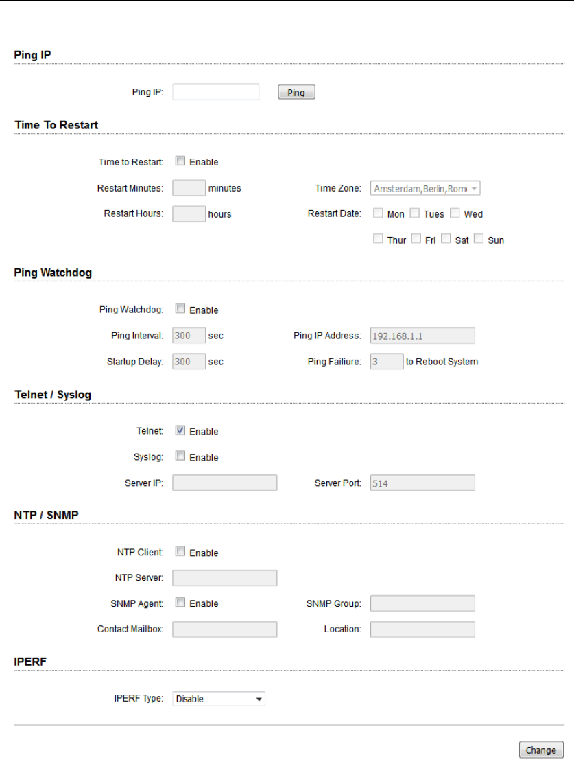
10 Tools
The Tools page is shown in Figure 30.
DH-PFM881 User Manual All Right Reserved
Page 38
Figure 30 Tools
Ping IP: User can input the destination IP address of another device, and click
Ping button. If that destination device is successfully connected to the
DH-PFM881 device, the result shows Alive, otherwise shows Not Alive.
Time To Restart: Timing restart equipment.

DH-PFM881 User Manual All Right Reserved
Page 39
Ping Watchdog:The ping watchdog sets the DH-PFM881 Device to continuously
ping a user-defined IP address (for example, it can be the IP address of the AP the
Client is connecting to). If it is unable to ping under the user defined constraints,
the DH-PFM881 device will automatically reboot. It is highly recommended that
users enable this feature at the side of “Station” and disable this feature at the side
of “Access Point”.
Ping Interval: Specify time interval (in seconds) between the ping requests are
sent by the Ping Watchdog.
Ping IP Address:Specify an IP address of the target which will be monitored by
Ping Watchdog. If this feature is enabled at the side of “Station”, Ping IP Address
should be the IP address of the AP the Client is connecting to.
Startup Delay: specify initial time delay (in seconds) until first ping request is sent
by the Ping Watchdog.
Ping Failure:Specify the number of ping replies. If the specified number of ping
replies is not received continuously, the Ping Watchdog will reboot the device.
Note:If users want to modify the parameters of Ping Watchdog, please
disable it first and then apply. When the web page shows that Ping
Watchdog is really disabled, users can now re-enable it with modified
parameters.
Telnet/Syslog:When telnet is enabled, the user can input command “Telnet
192.168.1.36” in the DOS window of Windows XP or Windows 7 PC, and then
telnet to the DH-PFM881 and manipulate the DH-PFM881 device. When telnet is
disabled, this operation is disabled.
When Syslog is enabled, and the System Log server’s IP is also set here, the log
information will be output to the Syslog server automatically.

DH-PFM881 User Manual All Right Reserved
Page 40
NTP/SNMP:If this NTP server is set, and the DH-PFM881 device can access to this
NTP server. DH-PFM881 device automatically calibrate the time and date
information with the NTP server and show the time information in the Status page.
When SNMP is enabled, use can check the working condition and information of
the DH-PFM881 device.
IPERF:Test equipment throughput. Device 1 select the "server” and the IPERF
interval is the time to display the throughput of the web page. Device 2 select the
"client" and the IPERF server to fill in the IP address of the device 1. The number of
IPERF threads for testing the number of threads running at the same time, it is
recommended to set up 10. IPERF test time for running IPERF seconds. IPERF
interval time is the time for the display of the throughput of the web page. For
testing, please click the "Test" button.
11 AC Management
AC Management page is shown in Figure 31。After this function is enabled, the AC
management system must be used.
Figure 31 AC Management
WTP Name:It’s the name of the device that is displayed on the AC.
WTP Location:It’s the location information that is displayed on the AC.
AC IP:This IP address can add up to eight, add the IP address is AC management

DH-PFM881 User Manual All Right Reserved
Page 41
interface IP and equipment is the same segment. After the AC control function is
enabled, click save, application, this time the device will take effect on the AC
configuration and restart, the device will join AC. After the AC control function is
enabled, the user is able to display the current state of the page on the device
page. After the AC control function is disabled, the user is able to modify the
device's page.
Note: the client must be able to join the AC after it is connected to an access
point that has been joined to the AC.
12 Logout
When you click logout button, the web will quit and return login web.
13 Network Configuration Examples
13.1 AP and Station Network
In the point-to-point working scenario, user can configure one DH-PFM881 device
to AP, and another to station mode, shown in Figure 32.
Figure 32 AP and Station network
To make the above network work, user need to use computers to configure the
two devices, and the detail configurations are described in the following:

DH-PFM881 User Manual All Right Reserved
Page 42
1. Configure the 2 DH-PFM881 devices to bridge mode, and disable the firewall,
and set different LAN IP for the 2 devices.
2. In wireless menu, configure the 2 devices to AP and station separately, set the
same SSID, the same channel bandwidth (20MHz for default), and set the same
encryption and password for both of the devices.
3. After the above setting is done, using one computer to ping the IP address of
the other computer, if they are connected, user can watch the connection
status in the Status page.
13.2 WDS Access Point, WDS Station, WDS Repeater Network
Figure 33 WDS Network
If there is a block, such as a building is in between the point-to-point connection,
one TuroBridge5E device can be put between the PTP connection as a relay, which
is “WDS AP, WDS Station, WDS Repeater” network, shown in the above Figure 33.
Three DH-PFM881 devices need to be configured as shown in Figure 33:
1. Configure the 3 devices to be bridge mode.
2. In the wireless menu, make the following configurations:
y Configure the 3 devices to WDS Access Point/WDS Repeater/WDS Station
separately
y Configure the 3 devices’ SSID to be the same
y Configure WDS AP and WDS Repeater frequency to be the same, for
example: 5785MHz
DH-PFM881 User Manual All Right Reserved
Page 43
y Configure the encryption method and password to be the same.
3. To verify if the network is correctly setup, please use the computer to connect
one of the three devices to ping the IP of any of the other two devices. If the ping
is successfully, the network connection works correctly.
13.3 Router Mode
In the Router mode, the DH-PFM881 works as a router and the network
connection is shown in Figure 34. In Figure 34, The POE port of the POE adaptor is
connected to the DH-PFM881 device’s POE port, and the LAN port of the POE
adaptor is connected to the internet. Meanwhile, the LAN port of DH-PFM881
device is connected to one computer, and then user can configure the device.
Figure 34 Router mode
After the above connection is done, configure the DH-PFM881 device using the
web based configuration menu.
1. In wireless page, set the device to route mode, disable the firewall. If the
internet provided by the ISP (DH-PFM881 connected to) has a DHCP server,
user can set DH-PFM881’s WAN mode to DHCP (Dynamic IP) so that it can
obtain the IP address automatically.
If the internet provided by the ISP(DH-PFM881 connected to) doesn’t have a
DHCP server, user need to manually configure all the parameters given by the
ISP, such as the WAN IP, WAN subnet mask, LAN IP, LAN subnet mask, Default
gateway, Primary DNS, Secondary DNS.
Note: LAN IP address and WAN IP address cannot be in the same IP segment.
For example, if LAN IP is 192.168.1.*, then WAN IP must be set to 192.168.2.* or
192.168.3.*.
2. In wireless page, set wireless mode to Access Point, set SSID to a random name,
and set output power to a value needed(Max output power is recommended
in the outdoor long distance environment). Then the user needs to choose a
wireless channel and an encryption method.

DH-PFM881 User Manual All Right Reserved
Page 44
3. Enable DHCPD.
4. When the above settings are done, use a computer to connect to DH-PFM881
device, and then check whether the connection is successfully.
Note: Users can check whether the connection is successfully by ping
DH-PFM881 device’s WAN IP address. If the ping is successfully, this
connection is successfully.
Appendix-A Troubleshooting
1. The device cannot be started after power on.
1. The Ethernet cable between the DH-PFM881 device and the POE adaptor is
more than 40 meters long.
2. The Ethernet cable quality is not good enough, and it should be Cat 5e or even
Cat 6 cable.
3. The RJ-45 plugs are not well connected.
2. Cannot be restored to the factory setting
Please manually push the Reset button for 5~10 seconds until all LEDs are light on,
then the user can log in the device by typing the default IP address 192.168.1.36.
3. My computer cannot be connected to the DH-PFM881.
Please try the following method to solve the problem:
1. Adjust the direction of the DH-PFM881 device.
Please rotate the DH-PFM881 device since the antenna inside the device is
directional.
2. Switch to other wireless channel

DH-PFM881 User Manual All Right Reserved
Page 45
Switch to other wireless channel ‘cause there are much interferences in this
channel.
3. Turn off the other interference sources
Maybe there are other WIFI devices nearby and cause interferences. Try to turn
off other WIFI devices nearby, or move DH-PFM881 to another clean
environment.
4. The signal strength between 2 DH-PFM881 devices is too
weak, and the throughput is low.
1. The DH-PFM881 AP and Station devices are not Line-of-Sight, or there are
blocks like a building in between the AP and Station devices.
2. The Station device and AP device is not aligned very well, including both
horizontally and vertically, since the antenna of the DH-PFM881 is directional.
3. The Station device is installed in the windows, and the windows glass shields
the wireless signal.
4. The distance between the AP and Station devices is too far.
5. The signal strength is high, but the throughput is low
1. There are too much interferences, or multi-path interferences. For example,
there are too much 2.4GHz or 5.8GHz WIFI device working nearby.
2. The RJ45 ports of the DH-PFM881 device don’t work well.
6. During the point-to-point or point-to-multi-point
connection, when ping from one device to another, the
latency is too long or the packet is lost.
1. Isolate the several APs if they are connected to one POE switch.

DH-PFM881 User Manual All Right Reserved
Page 46
2. The RJ45 ports are not connected very well.
7. The internet access is lost and the internet speed is low.
1. There are too much stations connected to one AP.
2. AP signal is too weak.
3. There are interference sources nearby.
4. Check the number of users and the max internet speed provided by the ISP.
This device complies with Part 15 of the FCC Rules. Operation is subject to the
following two conditions:
(1) This device may not cause harmful interference, and
(2) This device must accept any interference received, including interference that
may cause undesired operation.
Please take attention that changes or modification not expressly approved by the
party responsible for compliance could void the user’s authority to operate the
equipment.
Note: This product has been tested and found to comply with the limits for a Class
B digital device, pursuant to Part 15 of the FCC Rules. These limits are designed to
provide reasonable protection against harmful interference in a residential
installation. This product generates, uses, and can radiate radio frequency energy
and, if not installed and used in accordance with the instructions, may cause
harmful interference to radio communications. However, there is no guarantee that
interference will not occur in a particular installation. If this product does cause
harmful interference to radio or television reception, which can be determined by
turning the equipment off and on, the user is encouraged to try to correct the
interference by one or more of the following measures:
—Reorient or relocate the receiving antenna.
—Increase the separation between the equipment and receiver.
—Connect the equipment into an outlet on a circuit different from that to which the
receiver is connected.
—Consult the dealer or an experienced radio/TV technician for help.
This equipment should be installed and operated with a minimum distance 20cm
between the radiator and your body