Zhejiang Dahua Vision Technology DH-SD12D network PTZ Camera User Manual 1
Zhejiang Dahua Vision Technology Co., Ltd network PTZ Camera Users Manual 1
UserManual.wiki
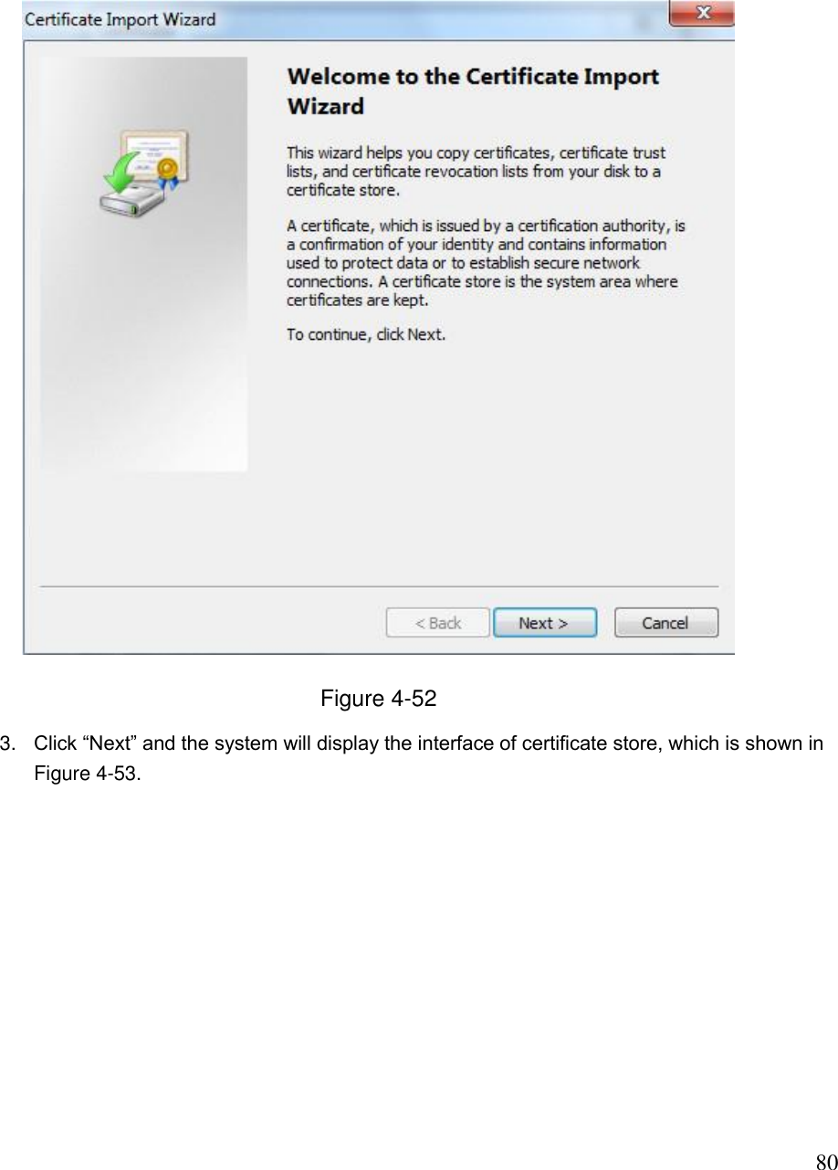
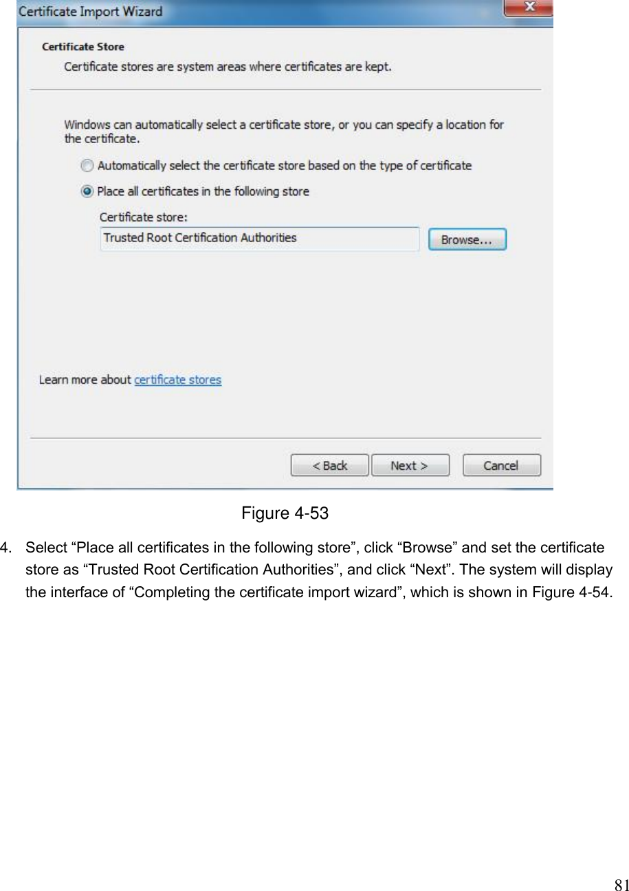
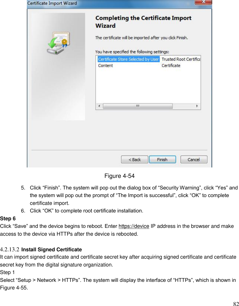
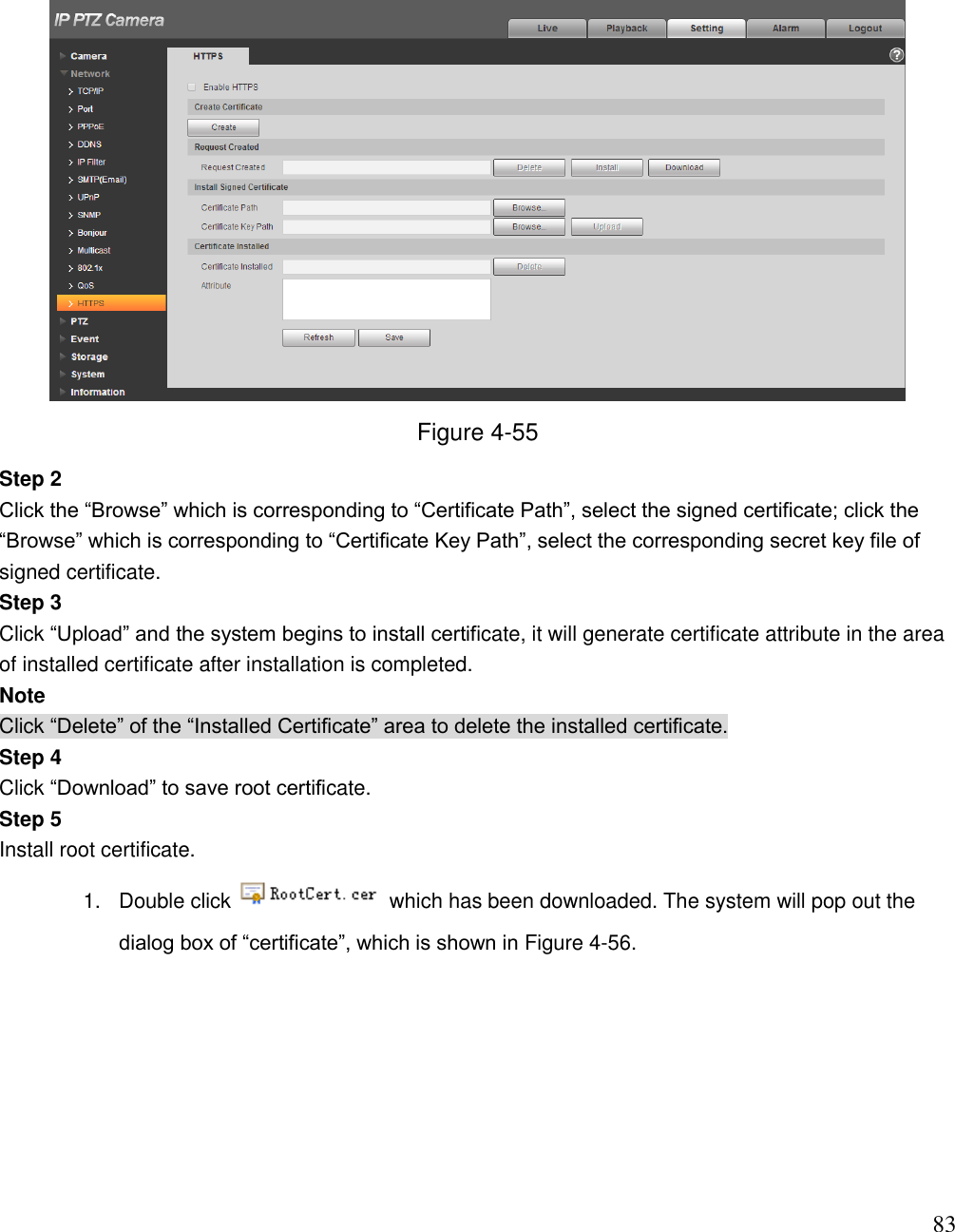
>
Zhejiang Dahua Vision Technology
>
DH-SD12D User Manual
>
Users Manual-1
Contents
1.
Users Manual-1
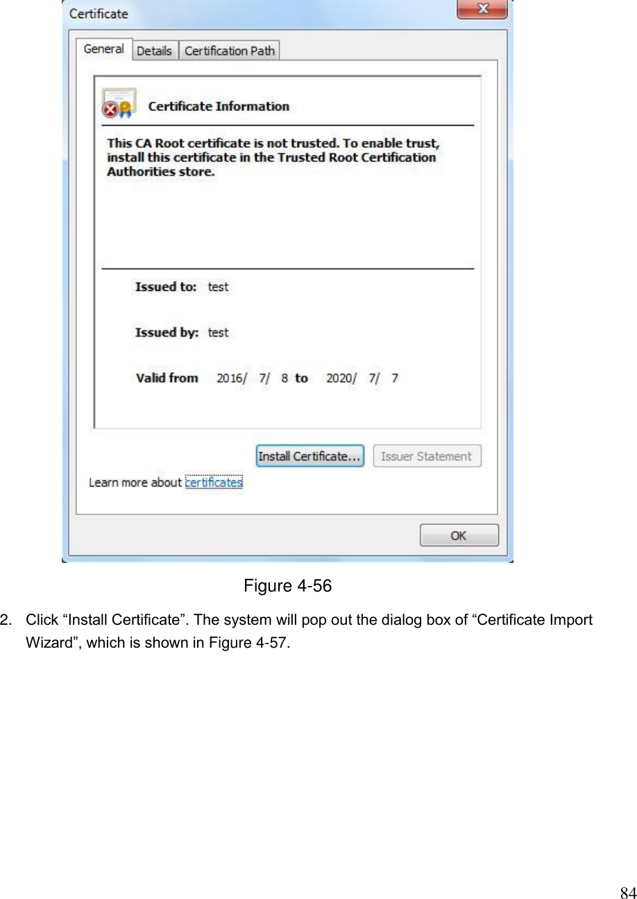
2.
Users Manual-2
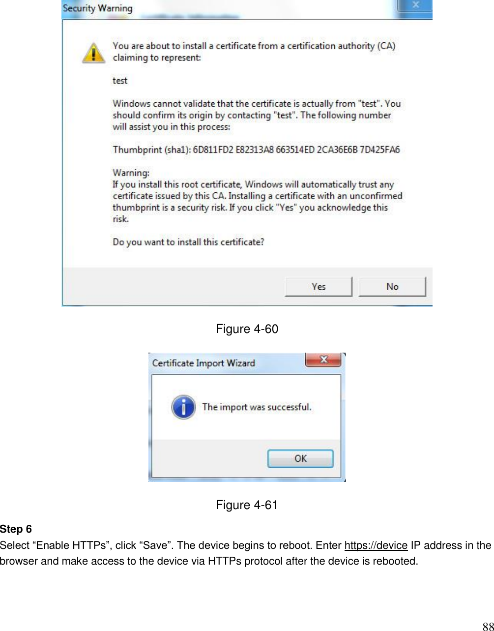
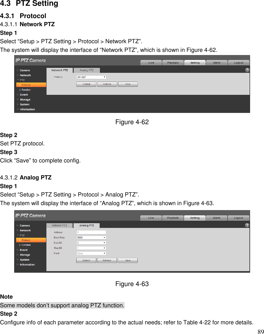
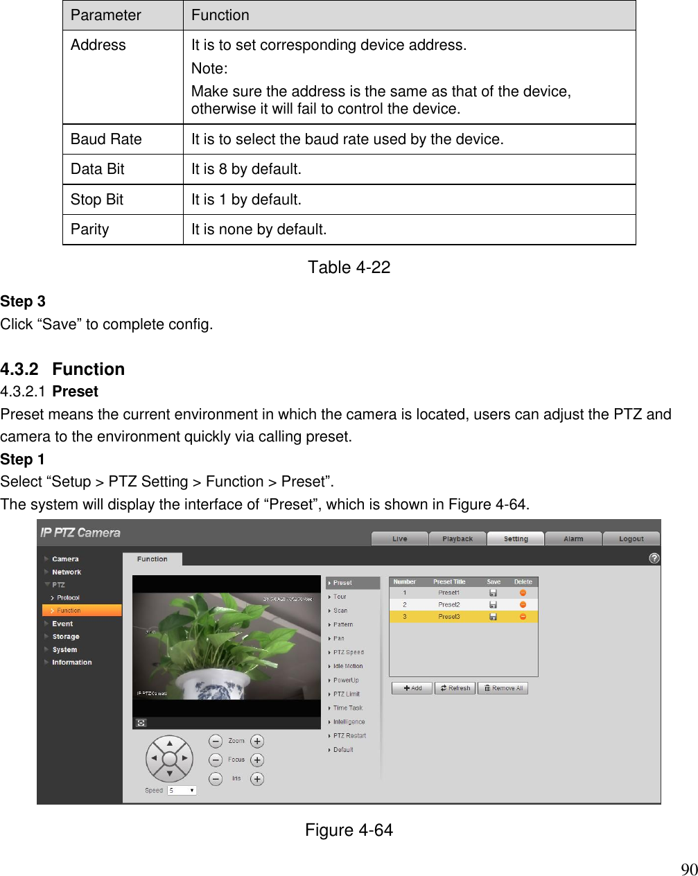
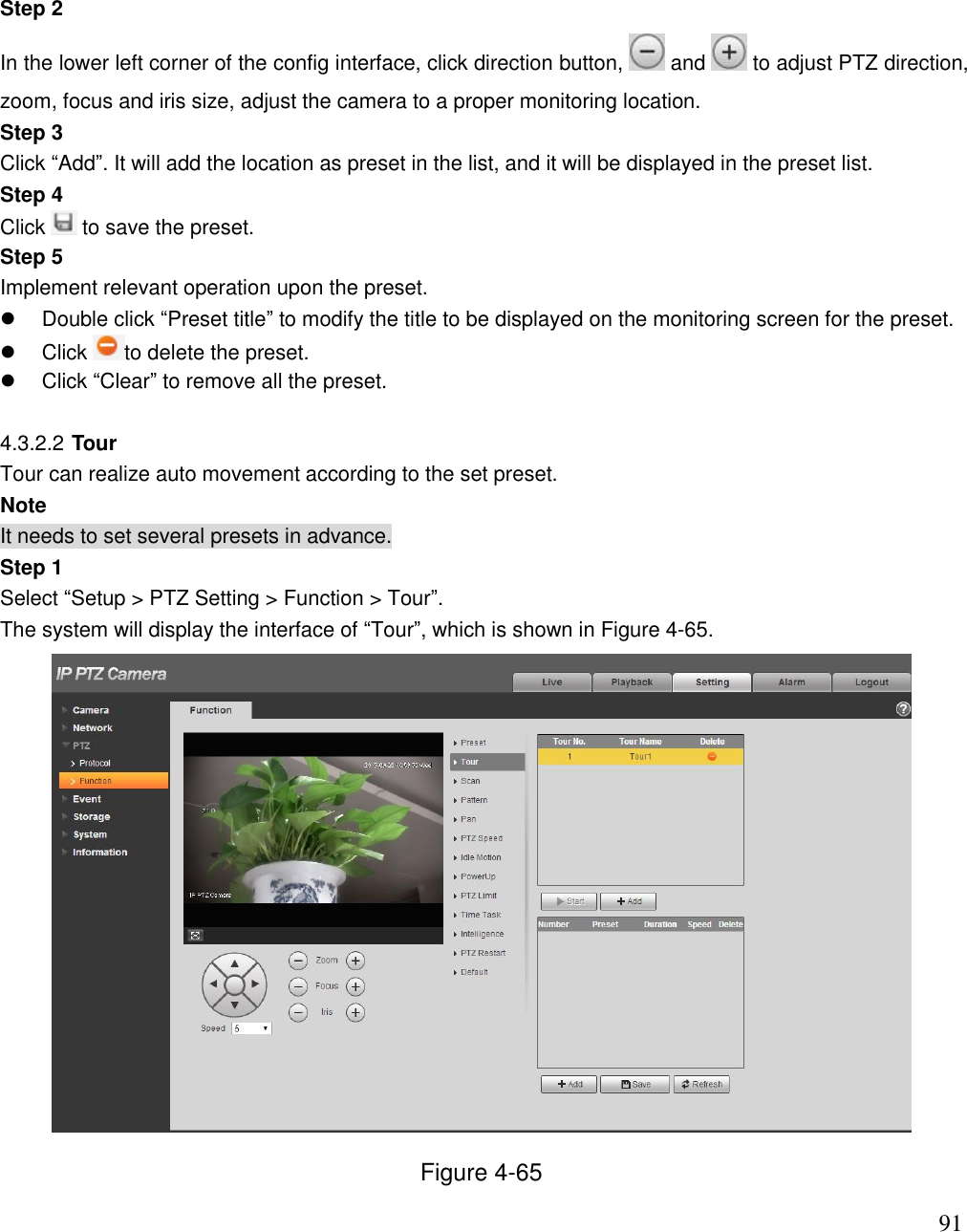
Users Manual-1
Navigation menu
Upload a User Manual
Namespaces
Wiki Guide
HTML
PDF
Info
Views
User Manual
Discussion / Help
Navigation