Zhejiang Dahua Vision Technology DH-SD1A PTZ Dome Camera User Manual speed dome operating manual
Zhejiang Dahua Vision Technology Co., Ltd PTZ Dome Camera speed dome operating manual
User Manual
Network Speed Dome Installation Manual
Version 1.0.0
i
Table of Contents
1 INSTALLATION PREPARATION ............................................................................................ 1
1.1 Basic Requirement .............................................................................................................. 1
1.2 Installation Check ................................................................................................................ 1
1.3 Cable Preparation ................................................................................................................ 1
1.3.1 The Min Specification Requirements of Cable ................................................................ 1
1.3.2 Cable Selection ............................................................................................................... 1
2 SPEED DOME INSTALLATION .............................................................................................. 2
2.1 Check Accessories .............................................................................................................. 2
2.2 Open Device ........................................................................................................................ 2
2.3 Micro SD Card Slot and Reset Button ................................................................................. 2
2.3.1 Use Reset Button ............................................................................................................ 3
2.3.2 Install Micro SD Card ...................................................................................................... 3
3 CEILING MOUNT .................................................................................................................... 4
3.1 Installation Component ........................................................................................................ 4
3.2 Device Installation ............................................................................................................... 4
3.2.1 Installation Conditions ..................................................................................................... 4
3.2.2 Installation Steps ............................................................................................................. 4
4 WALL MOUNT ......................................................................................................................... 8
4.1 Installation Component ........................................................................................................ 8
4.2 Device Installation ............................................................................................................... 8
4.2.1 Installation Conditions ..................................................................................................... 8
4.3 Installation Steps ................................................................................................................. 9
5 APPENDIX Ⅰ LIGHTNING PROOF AND SURGE PROTECTION (OUTDOORS) ............. 14
5.1 Lightning Protection (Indoors) ........................................................................................... 14
6 APPENDIX Ⅱ THE RELATIONSHIP BETWEEN DC 12V CABLE DIAMETER AND
TRANSMISSION DISTANCE ........................................................................................................ 16
7 APPENDIX Ⅳ WIRE GAUGE REFERENCE SHEET ........................................................... 18
ii
Welcome
Thank you for purchasing our speed dome!
Please read the following safeguards and warnings carefully before you install or use the
product!
iii
Important Safeguards and Warnings
Safety Measures
1. Qualified Engineer Needed
The installation engineer or maintenance engineer shall have corresponding CCTV system
installation certificate or maintenance qualification certificate.
The installation engineer or maintenance engineer shall have qualification certificate for work
at height.
The installation engineer or maintenance engineer shall have the basic knowledge and
operation technique for low-voltage cable layout and low-voltage electronic cable connection.
Please read the installation manual carefully and keep it well for future reference,
We are not liable for any problems caused by unauthorized modifications or attempted repair.
2. Lifting Appliance Requirement
Please select the proper speed dome installation mode and use the lifting appliances at the
safety environment.
The lifting appliances shall have the enough capacity to reach the installation height.
The lifting appliances shall have safe performance.
The precaution measures include two types: Warning and Note.
Warning: It is to alert you there is an optional risk of death or series injury!
Note: It is to alert you there is an optional risk of damage or property loss!
Warning
1. All installation and operation here should conform to your local electrical safety codes. We
assume no liability or responsibility for all the fires or electrical shock caused by improper
handling or installation.
2. Do not connect several speed domes to one power adapter. It may result in overheat or fire
if it exceeds the rated load.
3. Before you connect the cable, install or uninstall, or begin the daily maintenance work,
please turn off the power and unplug the power cable.
4. Please make sure the product is secured firmly on the wall or the ceiling.
5. Please turn off the power and unplug the power cable, If there is any smoke, disgusting
smell, or noise. Please contact your local retailer or customer service center for help.
iv
6. All the examination and repair work should be done by the qualified service engineers. We
are not liable for any problems caused by unauthorized modifications or attempted repair.
7. This device complies with Part 15 of the FCC Rules. Operation is subject to the following two
conditions:
(1) This device may not cause harmful interference, and
(2) This device must accept any interference received, including interference that may cause
undesired operation.
Attention that changes or modification not expressly approved by the party
responsible for compliance could void the user’s authority to operate the equipment.
Note
1. Safety Transportation
Heavy stress, violent vibration or water splash are not allowed during transportation, storage
and installation.
This series product must use split type package during the transportation.
We are not liable for any damage or problem resulting from the integrated package during
the transportation.
2. When device is malfunction
Shut down the device and disconnect the power cable immediately if there is smoke, abnormal
smell or abnormal function. Please contact your local retailer ASAP.
3. Do not try to dismantle or modify the device
There is risk of personal injury or device damage resulting from opening the shell.
Please contact your local retailer if there is internal setup or maintenance requirement.
We are not liable for any problems caused by unauthorized modifications or attempted repair.
4. Do not allow other object falling into the device
Please make sure there is no metal or inflammable, explosive substance in the speed dome.
The above mentioned objects in the device may result in fire, short-circuit or damage.
Please shut down the device and disconnect the power cable if there is water or liquid falling
into the camera. Please contact your local retailer ASAP.
Please pay attention to the camera. Avoid the sea water or rain to erode the camera.
5. Handle carefully
Do not allow this series product fall down to the ground.
Avoid heavy vibration.
6. Installation Environment Requirement
This series speed dome should be installed in a cool, dry place away from direct sunlight,
inflammable, explosive substances and etc.
v
This series product shall be away from the strong electromagnetism radiant, please keep it
away from wireless power, TV transmitter, transformer and etc.
7. Daily Maintenance
Please use the soft cloth to clean dust on the shell, or you can use soft cloth with cleaning
liquid to clean the shell and then use soft cloth to make it dry.
Do not use gasoline, dope thinner or other chemical material to clean the shell. It may result
in shell transfiguration or paint flake.
Do not allow the plastic or rubber material to touch the shell for a long time. It may result in
paint flake.
It is highly recommended to use the product with a lightning-proof device, which can realize
better lightning-proof effect.
This product has been tested and found to comply with the limits for a Class B digital device,
pursuant to Part 15 of the FCC Rules. These limits are designed to provide reasonable
protection against harmful interference in a residential installation. This product generates,
uses, and can radiate radio frequency energy and, if not installed and used in accordance
with the instructions, may cause harmful interference to radio communications. However,
there is no guarantee that interference will not occur in a particular installation. If this product
does cause harmful interference to radio or television reception, which can be determined by
turning the equipment off and on, the user is encouraged to try to correct the interference by
one or more of the following measures:
—Reorient or relocate the receiving antenna.
—Increase the separation between the equipment and receiver.
—Connect the equipment into an outlet on a circuit different from that to which the receiver
is connected.
—Consult the dealer or an experienced radio/TV technician for help.
This equipment should be installed and operated with a minimum distance 20cm between
the radiator and your body.
1
1 Installation Preparation
1.1 Basic Requirement
All installation and operation here should conform to your local electrical safety codes.
Before installation, please open the package and check all the components are included.
Please make sure the speed dome installation environment and installation mode can meet
your requirement. If there is special requirement, please contact your local retailer for more
information.
We assume no liability or responsibility for all the fires or electrical shock caused by
improper handling or installation.
1.2 Installation Check
Please make sure the installation environment has enough space to install the speed dome
and its corresponding installation components.
Please make sure the ceiling or wall can sustain 8X weight of the speed dome and its
corresponding components.
Please make sure the wall is thick enough to install expansion bolts (users need to prepare
by themselves).
1.3 Cable Preparation
1.3.1 The Min Specification Requirements of Cable
75 ohm impedance.
Full cable with copper conductor
95% knitted copper shield
1.3.2 Cable Selection
For DC 12V power supply device, please refer to appendix Ⅱ for more details.
2
2 Speed Dome Installation
2.1 Check Accessories
Before installation, please check the accessories one by one according to the packing list.
Please make sure all the components listed are includes.
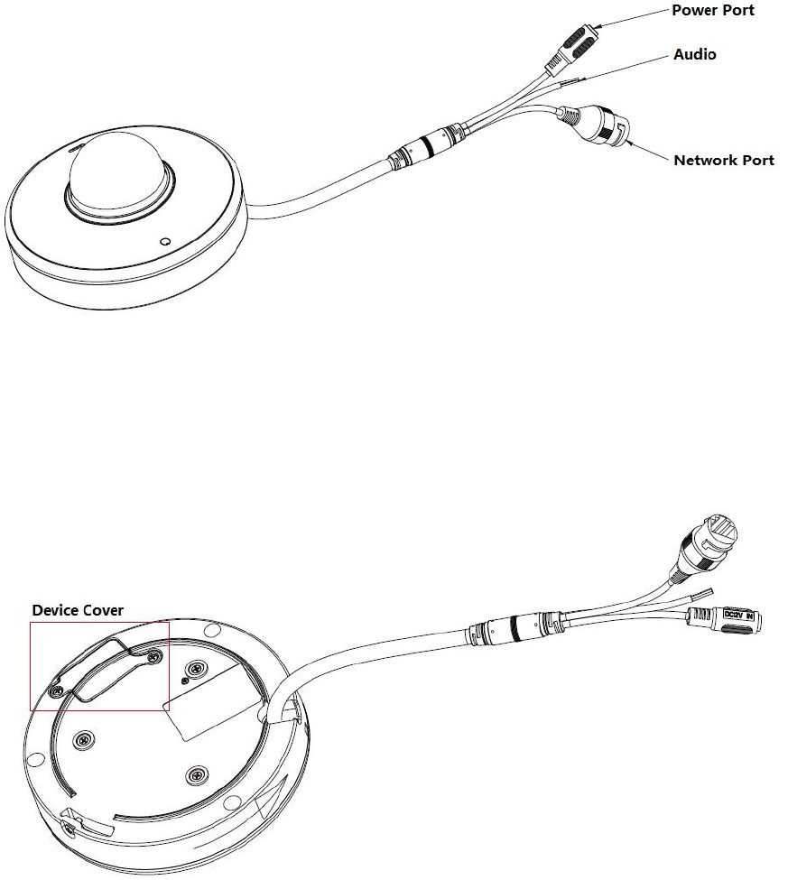
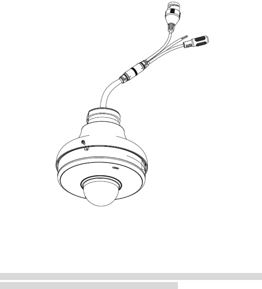
2.2 Open Device
Please open the box and then take out the device, which is shown in Figure 2-1.
Figure 2-1
2.3 Micro SD Card Slot and Reset Button
Turn over the device and you can see there is a cover located on the bottom of the speed dome,
which is shown in Figure 2-2.
Figure 2-2
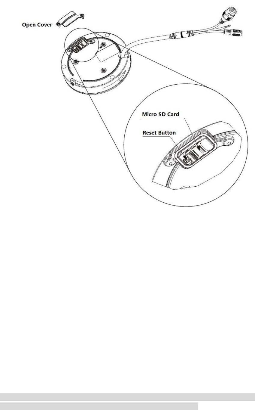
Use screwdriver to open the cover, and then you can see the reset button and Micro SD card slot,
which is shown in Figure 2-3.
3
Figure 2-3
2.3.1 Use Reset Button
Reset button is used to reset the network system.
Open the device cover, long press the reset button for over 10 seconds to reset the device, and
then all the settings will be restored back to factory default.
2.3.2 Install Micro SD Card
Micro SD card is used for data storage, the installation steps are shown as follows:
Step 1
(Pay attention to the pull and insert direction of Micro SD card slot) First press down the card slot
slightly and open it towards the OPEN direction (refer to the instruction on the slot slot), then the
card slot will become loose.
Step 2
Lay the Micro SD card; please be aware that the card metal surface is corresponding to the
golden finger of the card slot.
Step 3
Press the slot slightly and pull it according to the direction of CLOSE.
Note
Please make sure the Micro SD card is in the status of non-read & write when removing the
Micro SD card, otherwise it may cause data loss and SD card damage.
4
3 Ceiling Mount
3.1 Installation Component
It needs to use installation position map when the speed dome adopts ceiling mount, which is
shown in Figure 3-1.
Figure 3-1
3.2 Device Installation
3.2.1 Installation Conditions
Ceiling-mounted speed dome can be installed on the hard ceiling structure both indoors and
outdoors, the ceiling needs to meet the following installation conditions:
The ceiling shall be thick enough to install expansion bolts.
The ceiling shall sustain at least 8X weight of the speed dome, bracket and other
accessories.
3.2.2 Installation Steps
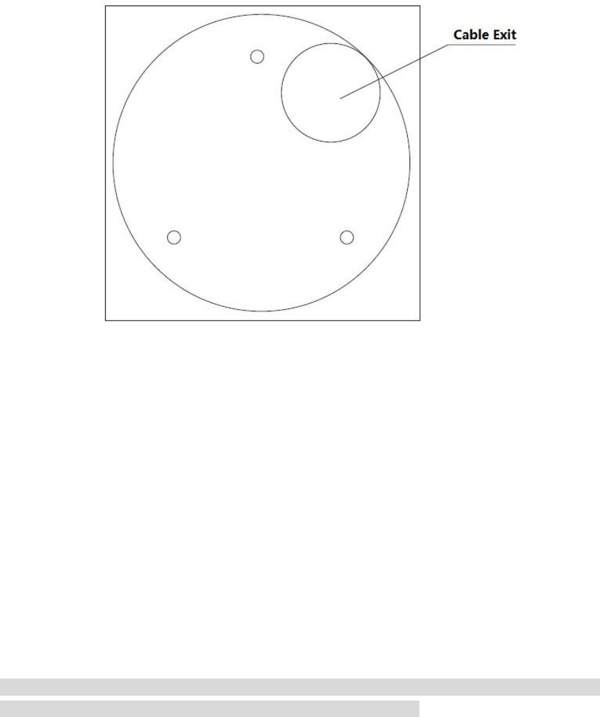
Step 1
Stick the installation position map of the speed dome on the ceiling after installation location is
confirmed, which is shown in Figure 3-2.
Note
Make sure the cable outlet is located in the range which needs no monitoring due to the optics
reason; otherwise, it will affect image effect and monitoring range.
5
Figure 3-2
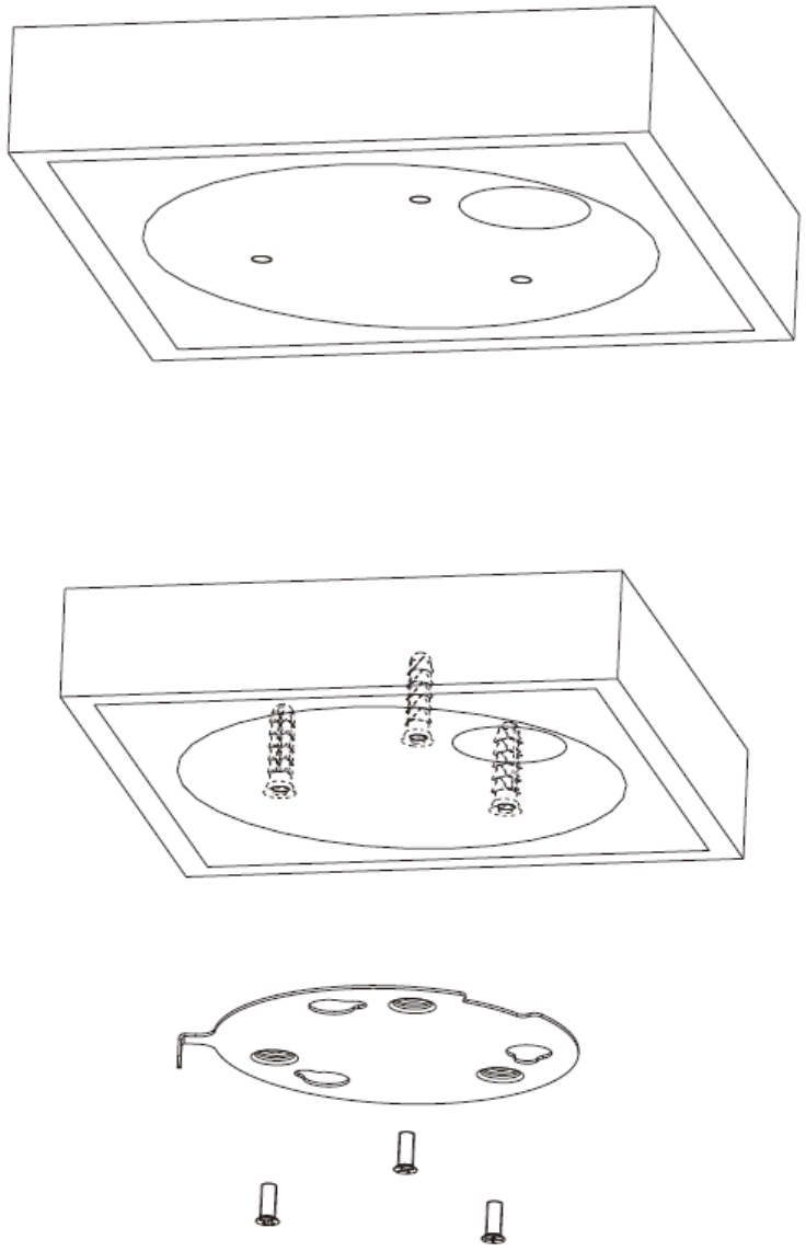
Step 2
Knock the expansion bolts into the mounting holes and use screws to fix the changeover plate on
the ceiling, which is shown in Figure 3-3.
Figure 3-3
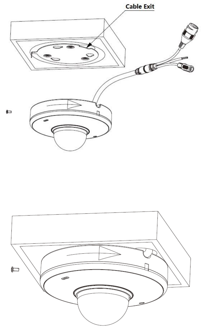
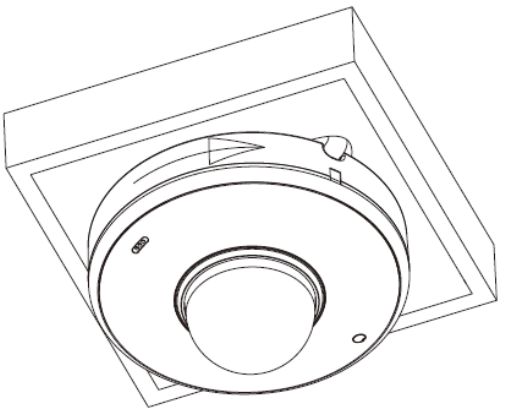
Step 3
Place the speed dome pedestal closely to the changeover plate after pulling the cable through
the hole, rotate it according to the arrow shown on the device edge and hang the speed dome on
the changeover plate, which is shown in Figure 3-4.
7
Figure 3-6
8
4 Wall Mount
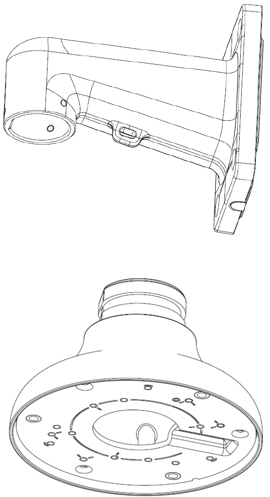
4.1 Installation Component
As for wall mount, it needs to use wall-mounted bracket and ceiling bracket, which is shown in
Figure 4-1 and Figure 4-2 respectively.
Figure 4-1
Figure 4-2
4.2 Device Installation
4.2.1 Installation Conditions
Wall-mounted speed dome can be installed on the hard wall structure both indoors and outdoors,
the wall needs to meet the following installation conditions:
The wall shall be thick enough to install expansion bolts.
9
The wall shall sustain at least 8X weight of the speed dome, bracket and other accessories.
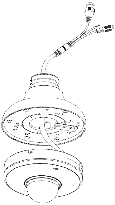
4.3 Installation Steps
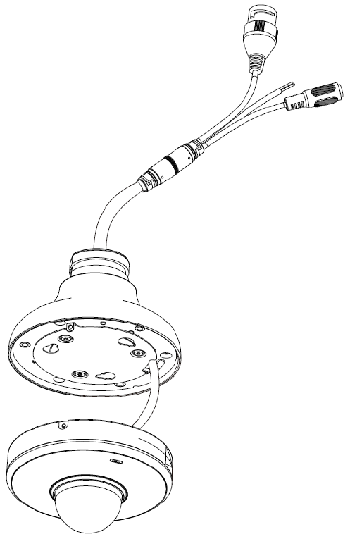
Step 1
Pull the device cable through the ceiling changeover plate, which is shown in Figure 4-3.
Figure 4-3
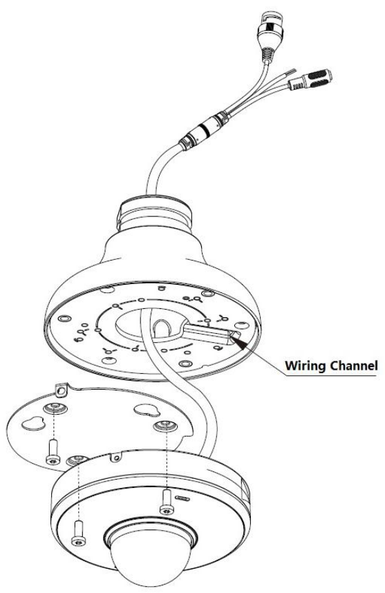
Step 2
Place the device cable closely into the wiring channel and use screws to install changeover plate
of speed dome on the ceiling changeover plate, which is shown in Figure 4-4.
12
Figure 4-6
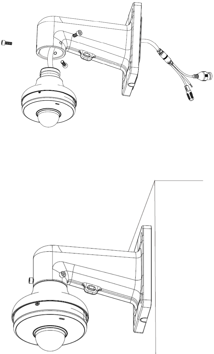
Step 5
Pull the device cable and ceiling changeover plate flange through the wall-mounted bracket, twist
the screws into the wall-mounted bracket, and then fix the changeover plate and speed dome on
the wall-mounted bracket, which is shown in Figure 4-7.
Note
Make sure the wiring channel is located in the range which needs no monitoring due to the optics
reason; otherwise, it will affect image effect and monitoring range.
14
5 APPENDIX Ⅰ LIGHTNING PROOF AND SURGE
PROTECTION (Outdoors)
This series speed dome adopts TVS lighting protection technology. It can effectively prevent
damages from various pulse signals below 6000W, such as sudden lighting and surge. While
maintaining your local electrical safety code, you still need to take necessary precaution
measures when installing the speed dome in the outdoor environment.
The distance between the signal transmission cable and high-voltage device (or high-voltage
cable) shall be at least 50 meters.
Outdoor cable layout shall go under the penthouse if possible.
For vast land, please use sealing steel tube under the land to implement cable layout and
connects one point to the earth. Open floor cable layout is forbidden.
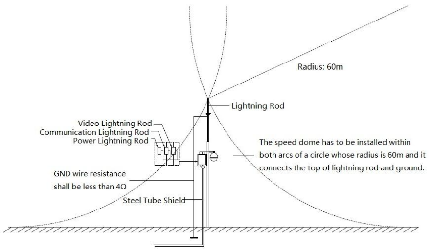
In area of strong thunderstorm hit or near high sensitive voltage (such as near high-voltage
transformer substation), you need to install additional high-power thunder protection device
or lightning rod.
The thunder protection and earth of the outdoor device and cable shall be considered in the
building whole thunder protection and conform to your local national or industry standard.
System shall adopt equal-potential wiring. The earth device shall meet anti-jamming and at
the same time conforms to your local electrical safety code. The earth device shall not short
circuit to N (neutral) line of high voltage power grid or mixed with other wires. When connect
the system to the earth alone, the earth resistance shall not be more than 4Ω and earth
cable cross-sectional area shall be no less than 25 mm². See Figure 5-1.
Figure 5-1
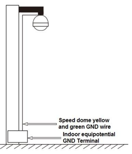
5.1 Lightning Protection (Indoors)

16
6 APPENDIX Ⅱ THE RELATIONSHIP BETWEEN DC 12V
CABLE DIAMETER AND TRANSMISSION DISTANCE
It is the recommended max transmission distance when the cable diameter is fixed and the DC
12V power consumption is below 10%.
For the DC power supply devices, the max permission voltage power consumption is 10%. The
cable listed in the table below is copper wire (the resistivity of copper is )
mm
Feet(m)
w
0.8000
1.000
1.250
2.000
5
122.13(37.23)
190.83
(58.16)
298.17
(90.88)
763.31
(232.66)
10
61.06(18.61)
95.41(29.08)
149.08
(45.44)
381.66
(116.33)
15
40.71(12.41)
63.61(19.39)
99.39(30.29)
254.44
(77.55)
20
30.53(9.31)
47.71(14.54)
74.54(22.72)
190.83
(58.16)
25
24.43(7.45)
38.17(11.63)
59.63(18.18)
152.66
(46.53)
30
20.35(6.20)
31.80(9.69)
49.69(15.15)
127.22
(38.78)
35
17.45(5.32)
27.26(8.31)
42.60(12.98)
109.04
(33.24)
40
15.27(4.65)
23.85(7.27)
37.27(11.36)
95.41
(29.08)
45
13.57(4.14)
21.20(6.46)
33.13(10.10)
84.81
(28.85)
50
12.21(3.72)
19.08(5.82)
29.82(9.09)
76.33
(23.27)
55
11.10(3.38)
17.35(5.29)
27.11(8.26)
69.39
(21.15)
60
10.18(3.10)
15.90(4.85)
24.85(7.57)
63.61
(19.39)
65
9.39(2.86)
14.68(4.47)
22.94(6.99)
58.72
(17.90)
70
8.72(2.66)
13.63(4.15)
21.30(6.49)
54.52
(16.62)
75
8.14(2.48)
12.72(3.88)
19.88(6.06)
50.89
(15.51)
80
7.63(2.33)
11.93(3.64)
18.64(5.68)
47.71
(14.54)
85
7.18(2.19)
11.23(3.42)
17.54(5.35)
44.90
(13.69)
90
6.78(2.07)
10.60(3.23)
16.56(5.05)
42.41
(12.93)
95
6.43(1.96)
10.04(3.06)
15.69(4.78)
40.17
(12.25)
100
6.11(1.86)
9.54(2.91)
14.91(4.54)
38.17
17
mm
Feet(m)
w
0.8000
1.000
1.250
2.000
(11.63)

18
7 APPENDIX Ⅳ WIRE GAUGE REFERENCE SHEET
Metric bare wire
diameter
(mm)
AWG
SWG
Bare wire cross
section
(mm2)
0.050
43
47
0.00196
0.060
42
46
0.00283
0.070
41
45
0.00385
0.080
40
44
0.00503
0.090
39
43
0.00636
0.100
38
42
0.00785
0.110
37
41
0.00950
0.130
36
39
0.01327
0.140
35
/
0.01539
0.160
34
37
0.02011
0.180
33
/
0.02545
0.200
32
35
0.03142
0.230
31
/
0.04115
0.250
30
33
0.04909
0.290
29
31
0.06605
0.330
28
30
0.08553
0.350
27
29
0.09621
0.400
26
28
0.1257
0.450
25
/
0.1602
0.560
24
24
0.2463
0.600
23
23
0.2827
0.710
22
22
0.3958
0.750
21
/
0.4417
0.800
20
21
0.5027
0.900
19
20
0.6362
1.000
18
19
0.7854
1.250
16
18
1.2266
1.500
15
/
1.7663
2.000
12
14
3.1420
2.500
/
/
4.9080
3.000
/
/
7.0683
Note
This manual is for reference only. Slight difference may be found in the user interface.
All the designs and software here are subject to change without prior written notice.
All trademarks and registered trademarks are the properties of their respective owners.
If there is any uncertainty or controversy, please refer to the final explanation of us.
Please visit our website or contact your local service engineer for more information.