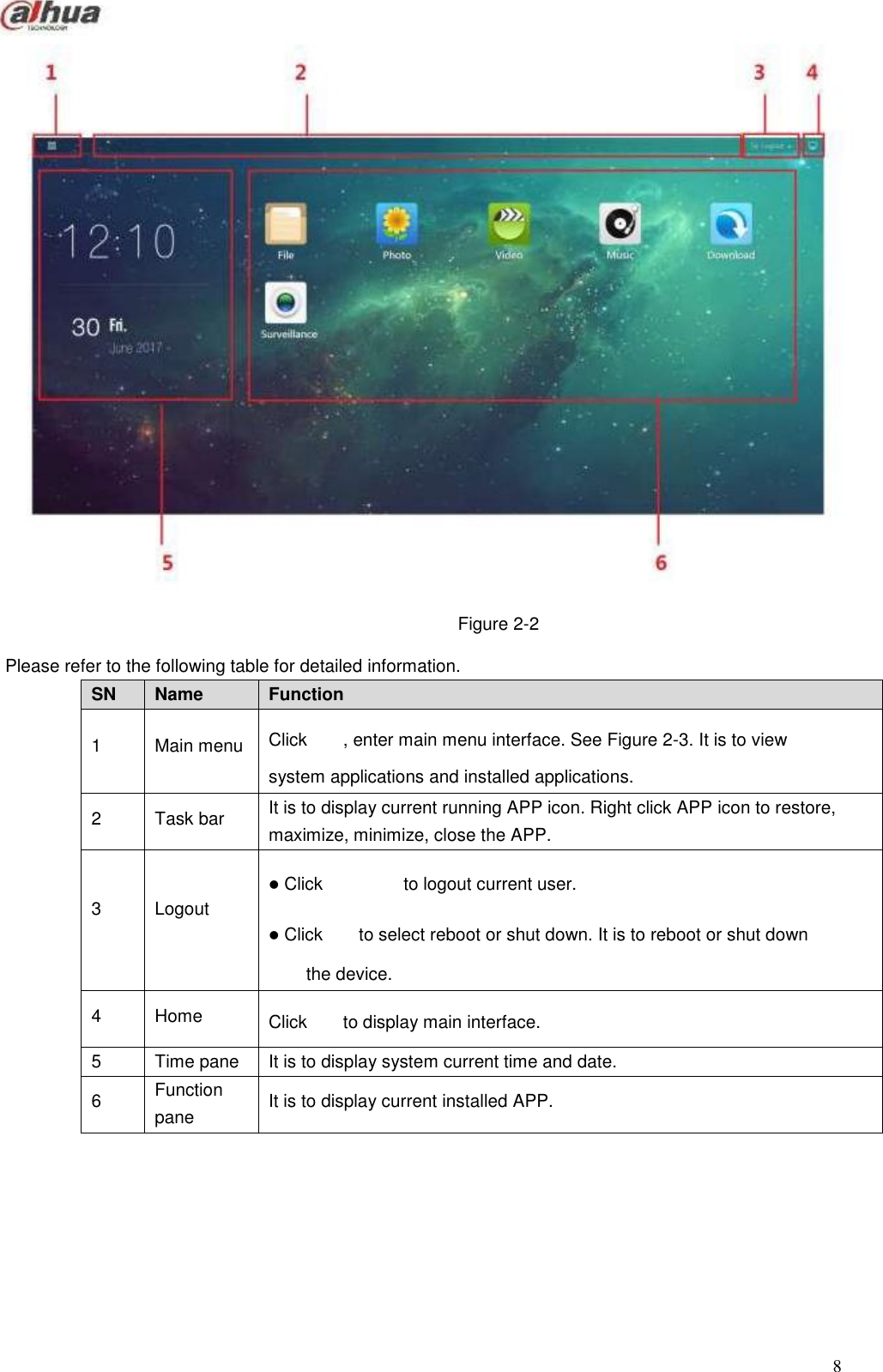
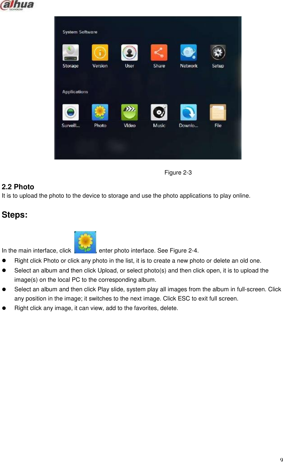
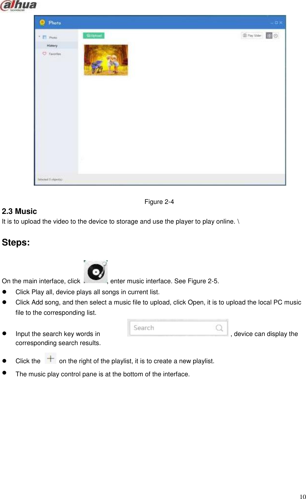
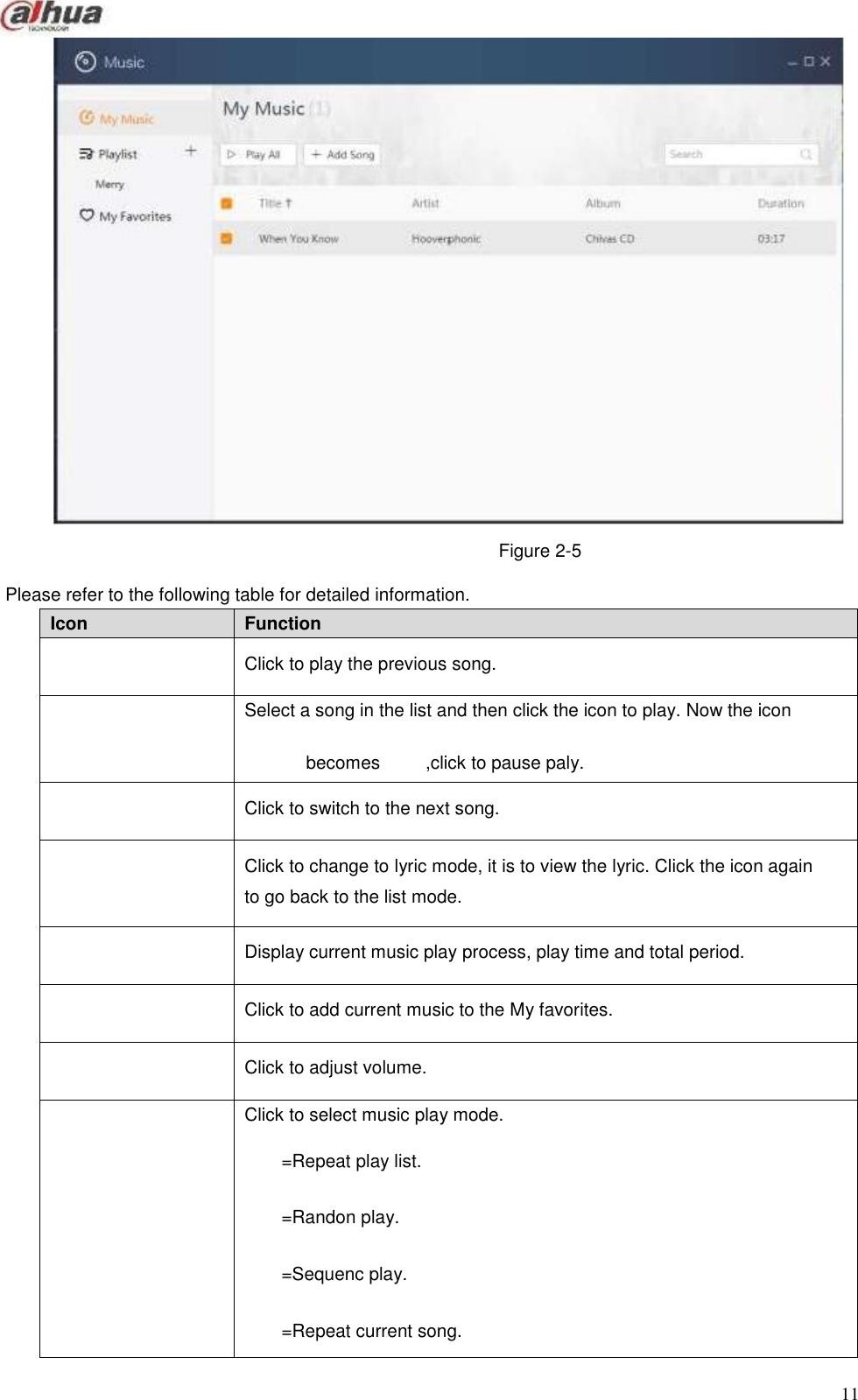
Zhejiang Dahua Vision Technology DHIH1C NETWORK ATTACHED STORAGE User Manual

Zhejiang Dahua Vision Technology Co., Ltd NETWORK ATTACHED STORAGE

User Manual

                           Network Attached Storage User’s Manual                               V 1.0.0
        Table of Contents   1   General Introduction ............................................................................................................................4 1.1 1.2 1.3 1.4 Overview........................................................................................................................................4 Front Panel/Rear Panel/Side Panel ..........................................................................................4 Packing List ...................................................................................................................................5 Open the Box to Check ...............................................................................................................5 2  WEB .......................................................................................................................................................7 2.1 2.2 2.3 2.4 2.5 2.6 Login...............................................................................................................................................7 Photo ..............................................................................................................................................9 Music ............................................................................................................................................10 Video ............................................................................................................................................12 File ................................................................................................................................................12 Download.....................................................................................................................................14 2.6.1 2.6.2 2.6.3 New Task ..............................................................................................................................15 Delete Task ...........................................................................................................................17 Restore Task ........................................................................................................................17 2.7 Surveillance.................................................................................................................................18 2.7.1 2.7.2 2.7.3 2.7.4 Initialization Settings ...........................................................................................................18 Remote Device Manager....................................................................................................25 Video .....................................................................................................................................29 Alarm .....................................................................................................................................32 2.8 Version .........................................................................................................................................33 3 4 5 ConfigTool............................................................................................................................................35 Appendix-Specifications ....................................................................................................................36 Appendix-Download Modes..............................................................................................................37                                i
        Welcome  Thank you for purchasing our device! This user’s manual is designed to be a reference tool for your system. Please open the accessory bag to check. Contact your local retailer ASAP if something is missing or damaged in the bag.                                                                 1
        Important Safeguards and Warnings  1.Electrical safety       All installation and operation here should conform to your local electrical safety codes. An apparatus with CLASS I construction shall be connected to a MAINS socket outlet with a protective earthing connection. Use a power supply which meets the requirements for SELV (Safety Extra Low Voltage) and complies with Limited Power Source according to IEC 60950-1. Refer to the device label for detailed information. The product must be grounded to reduce the risk of electric shock. We assume no liability or responsibility for all the fires or electric shock caused by improper handling or installation.  2.Transportation security    Heavy stress, violent vibration or water splash are not allowed during transportation, storage and installation.  3.Installation   Keep upwards. Handle with care. Do not apply power to the device before completing installation. Do not place objects on the device.  4.Qualified engineers needed   All the examination and repair work should be done by the qualified service engineers. We are not liable for any problems caused by unauthorized modifications or attempted repair.  5.Environment    The device should be installed in a cool, dry place away from direct sunlight, inflammable, explosive substances and etc. This series product shall be transported, storage and used in the specified environments.   6. Accessories Be sure to use all the accessories recommended by manufacturer. Before installation, please open the package and check all the components are included. Contact your local retailer ASAP if something is broken in your package.   FCC Statement This device complies with Part 15 of the FCC Rules. Operation is subject to the following two conditions: (1) This device may not cause harmful interference, and (2) This device must accept any interference received, including interference that may cause undesired operation.  Attention that changes or modification not expressly approved by the party responsible for compliance could void the user’s authority to operate the equipment.   2
  Icon Note DANGER Indicates a hazard with a high level of risk, which if not avoided, will result in death or serious injury. WARNING Indicates a potentially hazardous situation, which if not avoided, could result in serious device damage or person injury. CAUTION Indicates a potentially hazardous situation, which if not avoided, could result in device damage, data loss, performance degradation, or unexpected results. Anti-static Indicates it is the static sensitive device. Eletric shock risk Indicates presence of dangerous high voltage. There is a risk of electric shock to persons. High power laser radiation risk Indicates presence of high power laser radiation. Tips It is intended to help you to fix a problem or save your time. Note Provides additional information to emphasize or supplement important points of the main text.      Note: This product has been tested and found to comply with the limits for a Class B digital device, pursuant to Part 15 of the FCC Rules. These limits are designed to provide reasonable protection against harmful interference in a residential installation. This product generates, uses, and can radiate radio frequency energy and, if not installed and used in accordance with the instructions, may cause harmful interference to radio communications. However, there is no guarantee that interference will not occur in a particular installation. If this product does cause harmful interference to radio or television reception, which can be determined by turning the equipment off and on, the user is encouraged to try to correct the interference by one or more of the following measures: —Reorient or relocate the receiving antenna. —Increase the separation between the equipment and receiver. —Connect the equipment into an outlet on a circuit different from that to which the receiver is connected. —Consult the dealer or an experienced radio/TV technician for help.  This equipment should be installed and operated with a minimum distance 20cm between the radiator and your body.   Safety Instruction                                             3
              1 General Introduction  1.1 Overview  NAS (network attached storage) is a private network storage device for private data backup, sharing and storage. NAS provides the storage function (unit: TB) based on the Android OS. It supports 4K HDMI video output, HIFI (High-Fidelity) audio output. It supports cell phone APP remote management and data access, view, and downloads the record file and image remotely. After connected NAS to the network camera, it supports real-time preview, record playback, alarm event push and etc. It can provide total solutions for home security.   1.2 Front Panel/Rear Panel/Side Panel  The front panel is shown as in Figure 1-1.             Figure 1-1  The front panel is shown as in Figure 1-2.              Figure 1-2  The front panel is shown as below. See Figure 1-3.              Figure 1-3    4
  SN Indicator Light/Port Function 1 Power indicator light Power indicator light.  The light is off if it has not connected to the power sourcing.  The orange light is on during the system boot up process or press RESET button for a long time to reset the system.  The white light is on when system is working properly after initialization. 2 Signal inductor It is to receive the IR signal from the remote control. 3 HDD indicator light HDD status indicator light.  The light is off when there is no HDD or system cannot detect the HDD.  The orange light is on when HDD is error.  The white light is on when HDD is running properly. 4 Network port 100/1000Mbpsself-adaptive Ethernet port. Connect to network cable. 5 HDMI port High definition audio and video signal output port. It transmits uncompressed high definition video and multiple-channel data to the HDMI port of the display device. 6 USB2.0 port USB2.0 port. Connect to mouse, keyboard, USB device and etc. 7 Audio output port Audio output port. It is to output the analog audio signal to the devices such as the sound box. 8 Power port Power input port. Input 12V/1.5A power. 9 RESET Reset button. Press REST button for 8 seconds. The power indicator light becomes orange and device automatically begins reboot. Device restores factory default setup after reboot. 10 SD card port Micro SD card port. Max 128G storage space. 11 USB3.0 port USB3.0 port. Connect to mouse, keyboard, USB device and etc. Name Quantity Name Quantity NAS device 1 Power adapter 1 IR remote control 1 Network      connation cable 1 7# battery 1 HDMI cable 1 Quick Start Guide 1 - - SN Indicator Light/Port Function 1 Power indicator light Power indicator light.  The light is off if it has not connected to the power sourcing.  The orange light is on during the system boot up process or press RESET button for a long time to reset the system.  The white light is on when system is working properly after initialization. 2 Signal inductor It is to receive the IR signal from the remote control. 3 HDD indicator light HDD status indicator light.  The light is off when there is no HDD or system cannot detect the HDD.  The orange light is on when HDD is error.  The white light is on when HDD is running properly. 4 Network port 100/1000Mbpsself-adaptive Ethernet port. Connect to network cable.       Please refer to the following table for detailed information.                                                 1.3 Packing List  Please check the accessories according to the packing list.            1.4 Open the Box to Check Refer to the following table to check the device. Contact the local retailer or our service engineer if there is any problem.     5
  SN Name Contents 1 Whole package Appearance There is any visible damage or not. Package There is any accidental clash during transportation or not. Accessories Check all accessories are included in the bag or not. 2 Front panel and rear panel The model on the front panel Check the model with the purchase order. The label on the rear panel. It is neat and clean or not. Note Do not tear off, or discard the label. Usually we need you to represent the serial number when we provide the service after sales. 3 Case Appearance There is any visible damage or not. Check the data cable, power cable, fan cable, main board and etc. Check the connection is secure or not. Note Contact your local retailer or our service engineer if the connection is loosened.                                                                                6
                2 WEB  Use PC (personal computer) to access the device WEB to manage it.  Note Check the PC and device connection before login the WEB. Right now the browser supports Chrome and FireFox.   2.1 Login Use browser to access the device WEB, it is to access and manage the device remotely.   Steps:  Step 1 Step 2                               Step 3  Open browser and input the device IP address in the address column. Click Enter button. Enter WEB login interface. See Figure 2-1.                           Figure 2-1  Enter user name and password.  Note  The device default user name is admin and the password is admin.   Click   to display the input password contents. Step 4  Click Login. Enter main interface. See Figure 2-2.            7
    SN Name Function 1 Main menu Click        , enter main menu interface. See Figure 2-3. It is to view system applications and installed applications. 2 Task bar It is to display current running APP icon. Right click APP icon to restore, maximize, minimize, close the APP. 3 Logout  Click                  to logout current user.  Click        to select reboot or shut down. It is to reboot or shut down the device. 4 Home Click        to display main interface. 5 Time pane It is to display system current time and date. 6 Function pane It is to display current installed APP.                                       Figure 2-2  Please refer to the following table for detailed information.                                       8
                                     Figure 2-3  2.2 Photo It is to upload the photo to the device to storage and use the photo applications to play online.   Steps:     In the main interface, click     , enter photo interface. See Figure 2-4.   Right click Photo or click any photo in the list, it is to create a new photo or delete an old one. Select an album and then click Upload, or select photo(s) and then click open, it is to upload the image(s) on the local PC to the corresponding album. Select an album and then click Play slide, system play all images from the album in full-screen. Click any position in the image; it switches to the next image. Click ESC to exit full screen. Right click any image, it can view, add to the favorites, delete.                         9
                                            Figure 2-4 2.3 Music It is to upload the video to the device to storage and use the player to play online. \   Steps:     On the main interface, click     , enter music interface. See Figure 2-5. Click Play all, device plays all songs in current list. Click Add song, and then select a music file to upload, click Open, it is to upload the local PC music file to the corresponding list.    Input the search key words in corresponding search results.   , device can display the   Click the   on the right of the playlist, it is to create a new playlist.   The music play control pane is at the bottom of the interface.                     10
    Icon Function  Click to play the previous song.  Select a song in the list and then click the icon to play. Now the icon becomes          ,click to pause paly.  Click to switch to the next song.  Click to change to lyric mode, it is to view the lyric. Click the icon again to go back to the list mode.  Display current music play process, play time and total period.  Click to add current music to the My favorites.  Click to adjust volume.  Click to select music play mode. =Repeat play list. =Randon play. =Sequenc play. =Repeat current song.                                  Figure 2-5  Please refer to the following table for detailed information.                                           11
          Icon Function  Click to view current play music list. Click Clear to clear play list.  Display current played music amount. Click to view the played music list.                2.4 Video Upload the video file to the device to storage and use player to play online.   Steps:     In the main interface, click     , enter audio/video interface. See Figure 2-6.           Input key words in corresponding search results.    Move the mouse to the video file, device pops up    and click Enter button, device displays the      . Click the icon, it is to play the video file.                              Figure 2-6  2.5 File   It is to view the data file storage on the device.      12
      Icon Function  Click to go back to the previous path.  Click to cancel go back to the previous path  Click to refresh file list.  Input search key words, device displays corresponding file list.  Click to select file(s) to be uploaded, click Open to upload local PC to the device.  Click to add a new folder.        Steps:     In the main menu, click     , enter file interface. See Figure 2-7.  Right click the file name in the file list on the right pane, it is to download, copy/paste/cut, delete, rename the file, or view the file properties. Right click file, click download, it is to download the file to the local PC.                                   Figure 2-7  Please refer to the following table for detailed information.                       13
      Icon Function  Click to select file display mode. It includes list, small icon, medium icon and large icon.  Click to select file sequence. It includes name, size, type and time modified.                2.6 Download System supports BT(BitTorrent), magnet-uri ,HTTP/HTTPS, FTP/FTPS to download file. It max supports 5 download tasks at the same time. Refer to appendix for Download Mode for BT(BitTorrent), magnet-uri ,HTTP/HTTPS, FTP/FTPS detailed information.   Steps:     In the main menu, click     to enter download interface. See Figure 2-8.                                        Figure 2-8  Please refer to the following table for detailed information.      14
    SN Function 1 Download catalog bar.  Downloading: Display downloading, pause, to be downloaded or error task information.  Finished: Display finished task information.  Recycle: The deleted task information from the downloading list or the finished list. 2 Task operation bar  Click                to add new download task. Refer to chapter 2.6.1 New task for detailed information.                     Pause task in the downloading list, click the icon or right click mouse and then select start to resume download process.                       Select a download task in the downloading list and then click the icon or right click mouse to pause current task.                       Delete download task. Refer to chapter 2.6.2 Delete task for detailed information.               In the recycle select the deleted download task, and then click the icon or right click mouse to restore the task.                   Input the search key words, system displays the corresponding results. 3 Download main window. It is to display download task detailed information.  Name/size: Display download file name, size.  Transmit Speed: Display download speed and remaining time. If the download failed, system pops up failed to download dialogue box. The download process bar is grey.  Operation: Click        to begin download, click        to pause download. 4 View download state. Display current selected task amount and download total speed.                                                                 2.6.1 New Task System downloads new task by default after you created it. The state is downloading. If current download tasks have exceeded 5 (system max download threshold), the new task state is to be downloaded.   Steps:     Step 1     In the main interface, click     .         15
                    Enter download interface. See Figure 2-9.   Step 2   Click   . Enter Add task interface.                        Figure 2-9  Step 3   Input download link or add BT file. BT download: Add BT task and select corresponding .torrent file. Other download: Input download path. Different download modes have different download links. Please refer to the actual situation to set. Step 4  Select save path.  Click   to select path interface. See Figure 2-10. Click   to select saved path.   Note System save file to the previous path by default if you do not set new path here.                        Figure 2-10    16
                  Step 5       Click Download Now. Enter downloading list to view new task state and download process.   2.6.2 Delete Task Select a task in the list (download task, finished task or the task deleted in the recycle) and then click  , or right click mouse and then select delete, enter delete interface.   Note Check the box to select delete download file, system can delete the downloaded file at the same time.   2.6.3 Restore Task Go to the recycle to restore the download task.   Steps:     Step 1     In the main interface, click     . Enter download interface. See Figure 2-8. Step 2  Click Recycle bin. Enter recycle interface. See Figure 2-11.  Note The speed here displays deleting speed.                               Figure 2-11                                           17
                     Step 3        Select a task to be restored and then click        ,  System restore the task. Go to the downloading interface to view the download task.  Step 4   Click the   of the corresponding download task.  System begins downloading task again.   2.7 Surveillance    Click    , enter preview and monitor interface. See Figure 2-12. Connect to the camera, system can display real-time monitor video, playback record file, set camera parameters remotely.  Note If it is your first time to enter the preview interface, the window prompts you to install plugins. Please follow the prompts to install.                        Figure 2-12  2.7.1 Initialization Settings The initialization settings include add remote device and enable remote device record function.   2.7.1.1 Register Camera It is to manage camera such as add, edit, upgrade camera and etc. It supports to change channel name, bit rate parameters and etc.  Note System max supports 4 cameras.   Steps:  There are many ways to register the camera such as search and then add, add by IP address, batch add,   18
            using template to add. Here we introduce search and then add function.      Search and then add: Search to find the remote device and then add. This function is useful if you do not know the remote device IP address. Add by IP address: Add remote device by IP address. This function is useful if you know the remote device IP address, user name and password. Batch add: Add several remote cameras by the same time. Please make sure these remote devices are in the same IP segment such as (192.168.1.1~192.168.1.255), and the user name and password are the same. It can greatly enhance add efficiency. Import by template: Add remote device by import template.   Steps:  Step 1                            Step 2  On the surveillance interface, from Setup->Camera->Remote->Device. Enter Device interface. See Figure 2-13.                        Figure 2-13  Register camera. There are four ways: search and then add, input IP address and then add, batch add and use template to add.  Search and then add  1.  Click the   on the right side of the Auto search. Enter auto search interface. See Figure 2-14.                 19
          Icon/Item Function  Filter the remote device via the IP address or the MAC address. Select IP address or the MAC address from the dropdown list and then input the corresponding information, click Search button to view the results. Display filter Set filter criteria according to device type. Device only display the devices matching the criteria. It is suitable for the user to find the desired device(s).                            Figure 2-14 2.  Click Found device. Enter search results interface.  Note  The remote device on the added list will not be displayed on the searched results.  State column is to display current remote device has been initialized or not.  means it has been initialized. See Figure 2-15.                       Figure 2-15 Please refer to the following table for detailed information.              20
      Icon/Item Function Modify Check a device and then click the Modify button to change the remote device IP address. Note  Make sure the remote device is network camera and the manufacturer is private. Otherwise this function is null.  Change remote device IP address one by one. Search Click to search remote device again. Name Function Manufacturer Select manufacturer protocol from the dropdown list. IP address Set remote device IP address. Icon/Item Function Modify Check a device and then click the Modify button to change the remote device IP address. Note  Make sure the remote device is network camera and the manufacturer is private. Otherwise this function is null.  Change remote device IP address one by one.                     3.                     Double click remote device or check the remote device and then click Add. The selected remote device is added to the device list.  Input IP address and then add  1.  Input the   on the manual search, select add by IP address.  Enter add interface. See Figure 2-16.                                         Figure 2-16  2.  Set parameters.          21
    Name Function TCP port TCP port value. Default setup is 37777. Input the actual port number if necessary. Note Set TCP port value when manufacturer protocol is private. RTSP port RTSP port value. Default setup is 554. Input the actual port number if necessary. Note Do not need to set RTSP port value when manufacturer protocol is private or customized. HTTP port Set the HTTP port value of the remote device. The default setup is 80. Note Do not need to set HTTP port value when manufacturer protocol is private or customized. User name/password The user name and password to login the remote device. Channel amount Input channel amount or click Connect to get the remote device channel amount. Note Recommend you click the Connect button to get the remote device channel amount. If the input channel amount is not right, system cannot add remote device. Remote channel number. After getting remote device channel amount, click Set to select a channel to connect. Channel The channel to connect to the remote device. Service type Set the service type of the remote device. Note  The supported service type may vary if the device manufacturers are not the same. Refer to the actual interface for detailed information.  The default connection mode is TCP if the remote device is using the private protocol.                                                         3.                                                         Click OK to add.  Batch Add  1.  Click the   on the manual search pane, select batch add.  Enter add interface. See Figure 2-17.                22
                                                    Figure 2-17  2.      3. 4.  Set IP range you want to add. Note The batch add is for the remote devices on the same IP segment. Please set the fourth field of the IP address. Refer to the above table to set other parameters. Click OK to complete the add process.  Import template to add  1.  Click   to select save path and click Save to export template.   The exported template file default name is RemoteConfig_2016-12-13.csv. 2016-12-13 refers to the exported date. The import/export function is for the device of the same language. 2.  Input the remote device information and save the template.    WARNING  Do not change template file extension name, otherwise the import operation may fail.  3.  Click   to select template.  4. Note  Click Open to add the remote device from the template.  After adding the remote device, please check the status column: the   means the connection is   OK.   means the connection is fail.  Edit Remote Device  23
          Name Function Channel The server channel that have added the remote device . Select one or more channel(s). Check All to select all channels. State Display current channel status. Main stream Set the record type of the main stream, sub stream. It includes: manual, auto and close.  Manual: It has the highest priority. No matter channel is in which mode right now, click manual, the corresponding channel begins general record.  Auto: Automatically record video of the specified record type at the specified period. It includes motion detect record and general record.  Close:All-channel stops record. Sub stream               Click        or select a remote device and then click        to delete a remote device.   Click Refresh to refresh the remote device list.   2.7.1.2 Record Control The record includes auto record and manual record. After enable auto record function, the remote device can record at the specified period. Auto: Automatically record video of the specified record type at the specified period. Manual: Record for 24H. The record type is regular.    Warning Please make sure you have storage right before use the manual reord function.   Steps:  Step 1                            Step 2  On the surveillance interface, from Setup->Record control. Enter record control interface. See Figure 2-18.                        Figure 2-18  Enable the auto record of the corresponding channel. Set parameters.                                                   24
        Name Function Refresh Click to get the latest setup information. Default Click to restore default setup. Click OK to save.             2.7.2 Remote Device Manager It is to upgrade remote device, set parameters and etc.   2.7.2.1 Upgrade System supports upgrade the remote device via the WEB.   Preparation work  Make sure you have gotten corresponding upgrade file.   Steps:  Step 1                            Step 2  On the surveillance interface, From Setup->Camera->Remote->Upgrade. Enter upgrade interface. See Figure 2-19.                        Figure 2-19  Select a device to upgrade.  Note   Support private protocol only. The remote device connection status shall be  Use device type to filter if there are too many remote devices.   . Step 3 Step 4 Click Import to import upgrade file. Click Start upgrade button. System begins upgrading the remote device.   2.7.2.2 Info It is to view remote device information such as channel, IP address, manufacturer, type, applications  25
            serial number, video input amount, and audio input amount and external alarm amount.   Steps:  On the surveillance interface, from Setup->Camera->Remote->Info, enter info interface. See Figure 2-20. Click refresh to view the remote device information.                        Figure 2-20  2.7.2.3 Channel Name The server supports customized remote device channel name. It supports local save, sync to IPC, sync from IPC.   Steps:  On the surveillance interface, from Setup->Camera->Channel name, system displays channel name interface. See Figure 2-21. Double click a channel name to edit.                        Figure 2-21  26
    Name Function Local Save After changing a channel name, click      , it is to only change the remote device channel name on the server WEB. The remote device name remains the same. Sync to IPC After changing channel name, click      . It is to change the channel name on the server WEB and the remote device. Sync      from IPC Select a channel and then click      . It is to get remote device name. Refresh Click to get the latest setup information. Default Click to restore default setup. Refresh Click to get the latest setup information. Default Click to restore default setup. Click OK to save. Name Function Channel Please select a channel from the dropdown list. Enable video Check the box to enable sub stream video function. Code stream type It includes general stream, motion stream and alarm stream. The sub stream supports general bit streams only. Name Function Local Save After changing a channel name, click      , it is to only change the remote device channel name on the server WEB. The remote device name remains the same. Sync to IPC After changing channel name, click      . It is to change the channel name on the server WEB and the remote device. Sync      from IPC Select a channel and then click      . It is to get remote device name.       Please refer to the following table for detailed information.                          2.7.2.4 Encode Set the main stream and sub stream of the remote device.   Steps:  Step 1                            Step 2  On the surveillance interface, from Setup->Camera->Encode->Encode. System enters encode interface. See Figure 2-22.                        Figure 2-22  Set parameters.                                          27
  Name Function Compression It is to set video bit streams encode type.  H.264: Main Profile encode mode.  MJPEG: In this encode mode, the video needs general large bit stream to guarantee the video definition. You can use the max bit stream value in the recommend bit to get the better video output effect. Resolution It is to set video resolution. The higher the resolution is, the much clearer the video is. Frame rate (FPS) Set the frame rates per second. The higher the frame rate is, the attractive and fluent the video is. The frame rate may vary according to the resolution. Bit rate type There are two options: VBR and CBR.  CBR: Bit rates vary slightly. The bit rate remains general the same.  VBR: The bit rate may change according to the surveillance environment. Note  When the surveillance environment is changing slightly, please use CBR. When the surveillance environment is changing greatly, please use VBR.  In MJPEG mode, the bit stream control mode can only be CBR. Video quality It is to set the image quality. There are six levels:1,2,3,4,5,6. The higher the value is, the best the quality is. Note This item is customized only when the bit rate type is VBR. Bit rate Set bit rate value.  Main stream: Set the bit rate to change video quality. The higher the bit rate is, the better the video quality is. The reference bit rate provides the best recommended value range.  Sub stream: In CBR mode, the bit rate is general around the setup value. In VBR mode, it changes according to the video situation. But it remains the same with the setup value. Reference Bit rate Recommended bit rate value according to the resolution and frame rate you have set. Enable audio Check the box to enable audio function. The record file includes video and audio composite streams. Audio encode Select audio encode mode. Copy After set one channel, click copy to copy current channel setup to other channel(s). Refresh Click to get the latest setup information. Default Click to restore default setup.                                                                       Step 3                                                                       Click OK to save settings.   2.7.2.5 Overlay It is to set overlay title information on the surveillance video.    28
    Name Function Channel Please select a channel from the dropdown list. Cover-area It is to set privacy mask zone in the monitor video. The user cannot view the cover area. Note Each channel max supports 4 privacy mask zones. Time Title Check the box to enable this function. Click the Setup button and then input time. Drag the course title to the proper position and then click OK. Click Save button, device can display time on the real-time video and playback video. Channel Title Check the box to enable this function. Click the Setup button and then input a channel name. Drag the channel title to the proper position and then click OK. Click Save button, device can display channel name on the real-time video and playback video. Copy After set one channel setup, click Copy to copy current channel setup to other channel(s). Refresh Click to get the latest setup information. Default Click to restore default setup. Click OK to save default setup.        Steps:  Step 1                                                          Step 2  On the surveillance interface, from Setup->Camera->Encode->Overlay. Enter overlay interface. See Figure 2-23.                        Figure 2-23                                 Click OK to save settings.   2.7.3 Video It is to view the real-time video , and playback video record. 2.7.3.1 Real-time Preview On Monitor interface, from Monitor->Playback, enter preview interface. See Figure 2-24.  29
    SN Note 1 Real-time playback window. Click the online device on the channel list to view the real-time video.   Click the dropdown menu of the remote device, it is to enable/disable main stream/sub stream.   During the real-time monitor process, there are three buttons at the top right corner: digital zoom, audio and close.    : Click it, and then left click mouse to select a zone. It is to zoom in the specified zone. Click the icon again or right click mouse to restore original state.    :Click to enable/disable audio. There is no audio during real-time preview mode, if the audio function is null here.    : Click to close the video monitor on current window.                                     Figure 2-24  Please refer to the following table for detailed information.                                        30
      SN Note 2 Monitor channel list. Click the dropdown menu of the channel name to select main stream/sub stream to play.           : Remote device is offline.           : Remote device is online.           : The remote device is playing real-time video. Note Make sure the remote device supports sub stream and has enable sub stream function. 3 Switch real-time monitor window amount. System supports 1/4-window. Click        to go to full-screen preview interface. Click Ese to exit.                                   2.7.3.2 Playback   Steps:  Step 1                            Step 2      Step 3  On Monitor interface, from Monitor->Playback. Enter playback interface. See Figure 2-25.                        Figure 2-25  Select channel number from the channel list.  Note  System supports 1-channel playback only. Select date and bit stream type.  Click the date, the time bar displays current date record information.     31
                               Bit stream includes main stream/sub stream.  Step 4   Click   or click any position on the time bar, it is to playback the record file.    Click   , system begins playing from the beginning time of the record time.   Click any position in the time bar, system begins playing from the selected time.  Note  During the playback process:   Click   to stop playing record.    Click   to mute the audio. Drag the   to set volume.    Click   to go to full-screen. Click Esc to exit full-screen.   2.7.4 Alarm It is to view alarm log occurred time, channel number, alarm type and process state.     CAUTION The alarm information in the following interface is for current login user only. After login again, system clears all alarm information.   Steps:    Click    , enter alarm interface. See Figure 2-26.  Set alarm search criteria to view the detailed information.                            32
      Name Function Time Set alarm log search period. Alarm type Set alarm type. Process state Set alarm process state. It includes:all,pending, fixed, false alarm and ignored.                                             Figure 2-26  Please refer to the following table for detailed information.           2.8 Version  Click   in the main interface, enter version interface. See Figure 2-27.                     33
                                        Figure 2-27                                           34
        3 ConfigTool Please use ConfigTool to search, access and set the NAS device. Refer to ConfigTool User’s manual for detailed information.                                                                    35
  Name Function OS OS Google CTS Certified Android5.1OS CPU Quard 64-bit high performance ARM CortexA53, max 2.0GHz Memory 2GB DDR3 Flash 4GB eMMC HDD 2.5-inch HDD, support 1T/2T and more. Audio/Video Audio Decode DTS HD, DTS M6, Dolby Digital Plus Output Resolution Max 4K(3840×2160)output, support HDR Video Decode H.265 4K2K@60f/s, H.264 4K2K@30f/s, VP9 4K2K@60f/s, MPEG1/2/4、VC-1 1920&1080P@60f/s Network WIFI IEEE 802.11b/g/n, band 2.4G Port Power port 1 power input port, 12V/1.5A power Network Port 1 100/1000Mbps self-adaptive Ethernet port HDMI Port 1 HDMI port USB Port 1 USB2.0 port, 1 USB3.0 port Audio Output Port 1 3.5mm audio output port SD Card Port 1 Micro SD card port. Max 128G expansion storage space. Button RESET button 1 reset button. Press for at least 8 seconds to restore factory default setup. Indicator Light Power Indicator Light 1 power indicator light HDD Indicator Light 1 HDD indicator light Other Working Temperature -10℃~40℃ Working Humidity 10%~90% Lightening Proof IEC61000-4-5 compliance,Level 2 Anti-Static GB9254 Class B Shock-Proof 1 meter shock proof Dimensions (L×W×H) 229.8mm×158.9mm×32.1mm Weight 550g(With HDD)       4 Appendix-Specifications                                                                        36
  Download Mode Note Magnet URI Download Magnet URI is a special link. It is different from the tradition download based on the file position or the general link. The Magnet URI downloads the Hash results from contents of different files and generates one pure digital fingerprint. It uses the fingerprint to identify the file. The fingerprint can be generated from anyone from any file. So the magnet URI download does not need the support from any organizations or party and has high recognition rate. It is easy to spread. The      standard      magnet-uri   download      format      is      similar      to magnet:?xt=urn:btih:ESTZ24OIGMS5VGYTUV73E3Y5P7CH4XMG。 HTTP Download HTTP is so called Hyper Text Transportation Protocol. It is the underlying protocol used by the World Wide Web and this protocol defines how messages are      formatted      and      transmitted,      and      what      actions Web servers and browsers should take in response to various commands. HTTP download format is similar to http://www.aaa.com/a.jpg。 HTTPS Download HTTPS is so called Hyper Text Transportation Protocol over Secure Socket Layer. It is a communications protocol for secure communication over a computer network which is widely used on the Internet. HTTPS download format is similar to https://www.aaa.com/a.jpg. FTP Download FTP is so called File Transportation Protocol. It is a standard network protocol used for the transfer of computer filesbetween a client and server on a computer network. Its download theroy is similar to the HTTP, but it needs a user name and password to login the FTP server (User can use the general account or do not need to input the user name or password if the FTP server supports anonimous login. ) FTP    download    format    is    similar    to    ftp://ftp.ftpserver.com/ 或 ftp://192.168.12.34. FTPS Download FTPS is so called File Transportation Protocol over Secure Socket Layer. It uses SSl protocol to transmit encrypted FTP data. It is a FTP method for secure communication. FTPS download format is similar to ftps://ftp.ftpserver.com/ or ftps://192.168.12.34.       5 Appendix-Download Modes                                                                        37
           Note ••••• This manual for reference only. Slight difference may be found in the user interface. All the designs and software here are subject to change without prior written notice. All trademarks and registered trademarks are the properties of their respective owners. If there is any uncertainty or controversy, please refer to the final explanation of us. Please visit our website or contact your local service engineer for more information.                                                              38

Navigation menu