Zhejiang Dahua Vision Technology IPC-HFW1XXXS IP CAMERA User Manual x
Zhejiang Dahua Vision Technology Co., Ltd IP CAMERA x
Users Manual

Dahua IR Wi-Fi Bullet Camera Quick Start Guide
V 1.0.2
Dahua Vision Technology CO., LTD
2
This device complies with Part 15 of the FCC Rules. Operation is subject to the following two
conditions:
(1) This device may not cause harmful interference, and
(2) This device must accept any interference received, including interference that may cause
undesired operation.
Attention that changes or modification not expressly approved by the party responsible for
compliance could void the user’s authority to operate the equipment.
Note: This product has been tested and found to comply with the limits for a Class B digital
device, pursuant to Part 15 of the FCC Rules. These limits are designed to provide reasonable
protection against harmful interference in a residential installation. This product generates,
uses, and can radiate radio frequency energy and, if not installed and used in accordance with
the instructions, may cause harmful interference to radio communications. However, there is
no guarantee that interference will not occur in a particular installation. If this product does
cause harmful interference to radio or television reception, which can be determined by turning
the equipment off and on, the user is encouraged to try to correct the interference by one or
more of the following measures:
—Reorient or relocate the receiving antenna.
—Increase the separation between the equipment and receiver.
—Connect the equipment into an outlet on a circuit different from that to which the receiver is
connected.
—Consult the dealer or an experienced radio/TV technician for help.
This equipment should be installed and operated with a minimum distance 20cm between the
radiator and your body
1
1
11
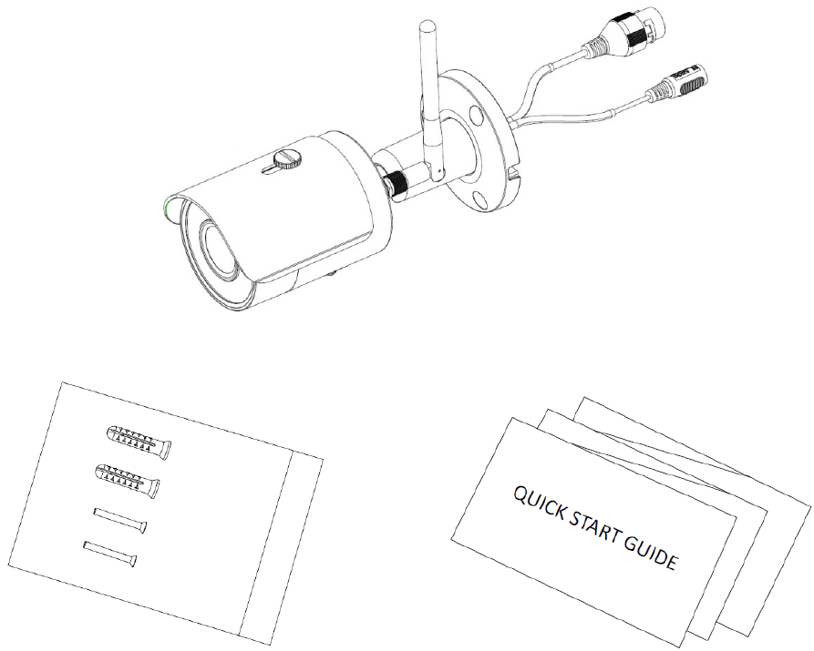
1 Packing List
Packing List Packing List
Packing List
Device × 1
Screw Package ×1 QSG ×1
2
2
22
2 Product Appearance
Product Appearance Product Appearance
Product Appearance
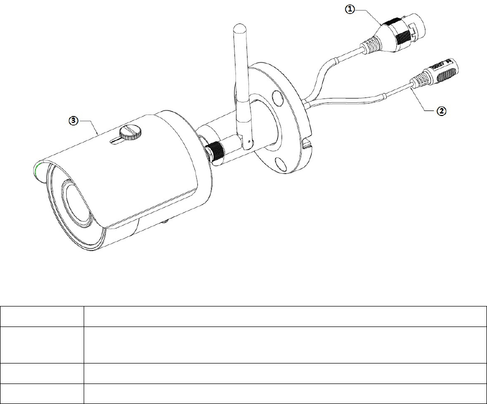
Figure 2-1
Please refer to the following sheet for more details about the device.
SN
Name
① Ethernet port
Note
The device can be directly connected to computer.
② Power port
③ Unit device
Sheet 2-1
3
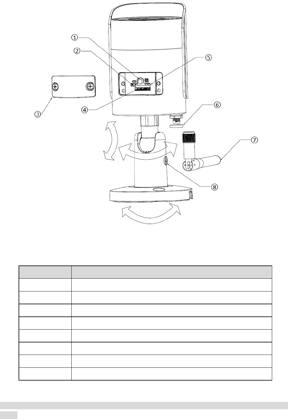
Figure 2-2
Please refer to the following sheet for more details about each component.
Sheet 2-2
Note:
For reset, long press for 8 seconds and then the light off; For WPS (Wi-Fi Protected Setup), one quick
press.
SN Name
① Reset/ WPS (Wi-Fi Protected Setup) button
② Indicator light 1
③ Lower cover
④ Micro SD card slot
⑤ Indicator light 2
⑥ Waterproof ring
⑦ Wi-Fi antenna
⑧ Locking screw

4
Please refer to the following sheet for more details about status of indicator light.
Indicator light status Device status
Red light stably on Booting
Green light slow flashing Booting completed, await Wi-Fi config,
enter smart config status;
Green light quick flashing
Wi-Fi smart config in progress, including
WPS (Wi-Fi Protected Setup),
management frame, etc.
Green light stably on Wi-Fi connection succeeded, operate
normally.
Red and green lights flash alternately Device upgrade
Red light slow flashing Network disconnection.
Red light quick flashing Device fail to boot up; alarm or SD card
does not work
Sheet 2-3
5
3
33
3 Operate by Easy4ip APP
Operate by Easy4ip APPOperate by Easy4ip APP
Operate by Easy4ip APP
Step 1
Power on the device with power adapter.
Step 2
Connect your smart phone to your Wi-Fi network. Scan the “Easy4ip” QR on the packing box,
download and install the Easy4ip APP.
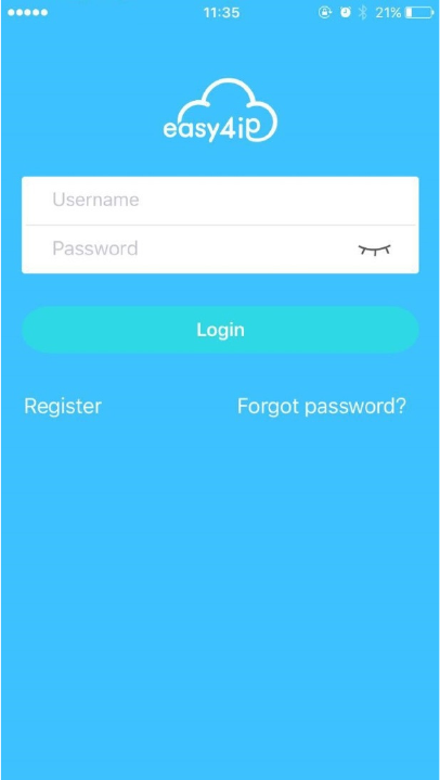
Step 3
Open Easy4ip APP (take IOS as an example), tap “Login” to login the APP, see Figure 3-1. Please
register an account for your first use.
Figure 3-1
Step 4
Please tap “+” to add new devices after you log in your account.

6
Figure 3-2
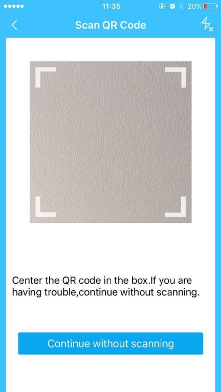
Step 5
Scan the QR code on the back of the camera to get the SN, you can also tap “Continue without
scanning” and manually input the SN number on the next page.
7
Figure 3-3
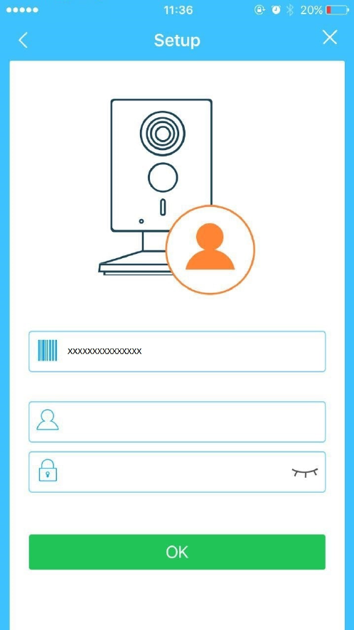
Step 6
Fill in the Username and Password of the new camera, both of which are admin by default.
8
Figure 3-4
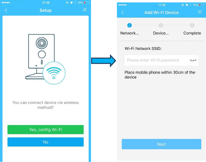
Step 7
Select “Yes, config Wi-Fi”, and fill in your Wi-Fi password, then tap “Next”.
9
Figure 3-5 Figure 3-6
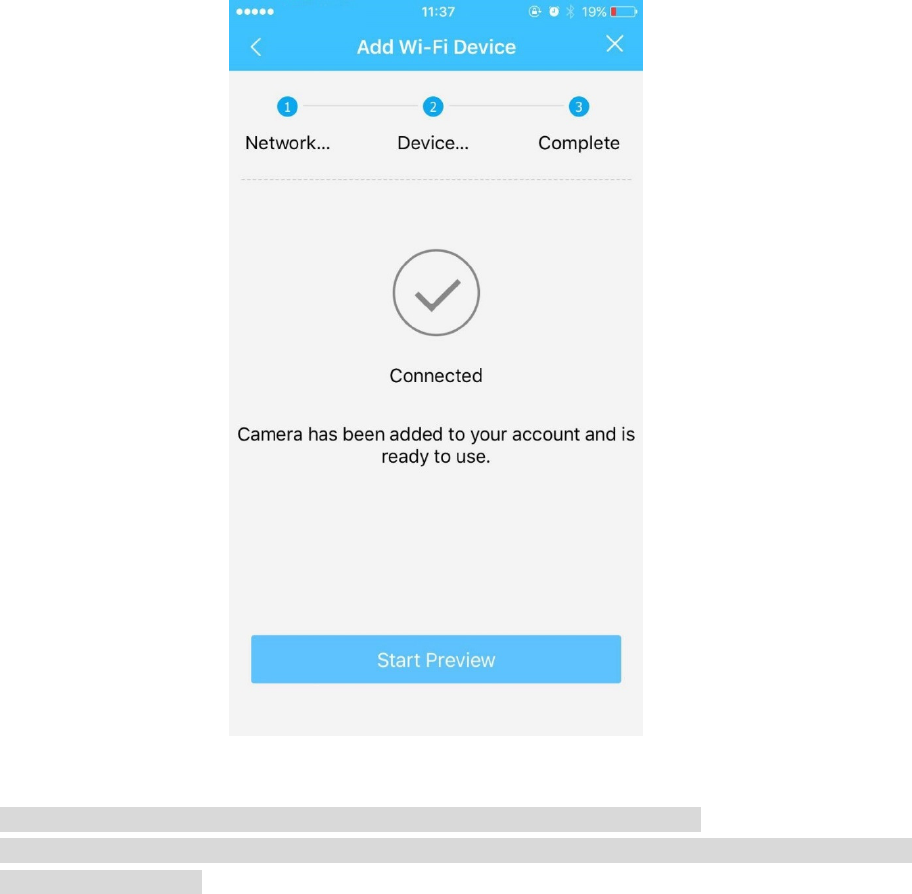
Step 8
Your Camera will be added to your account.
10
Figure 3-7
Note:
If you have more cameras, please follow steps 4-8 to add them one by one.
If you want to change the Wi-Fi signal, please reset the camera to factory default and repeat steps
4-8 to add the device.
11
4
4 4
4 Network Configuration
Network Configuration Network Configuration
Network Configuration
The IP address of all the cameras is the same when leaving factory (default IP 192.168.1.108). To
make the camera access to the network smoothly, please plan the available IP segment reasonably
according to the actual network environment.
NOTE:
The camera can be configured only when the IP addresses of the camera and the computer are in the
same network segment.
Step 1
Power on the device with power adapter,Connect the device to computer.
Step 2
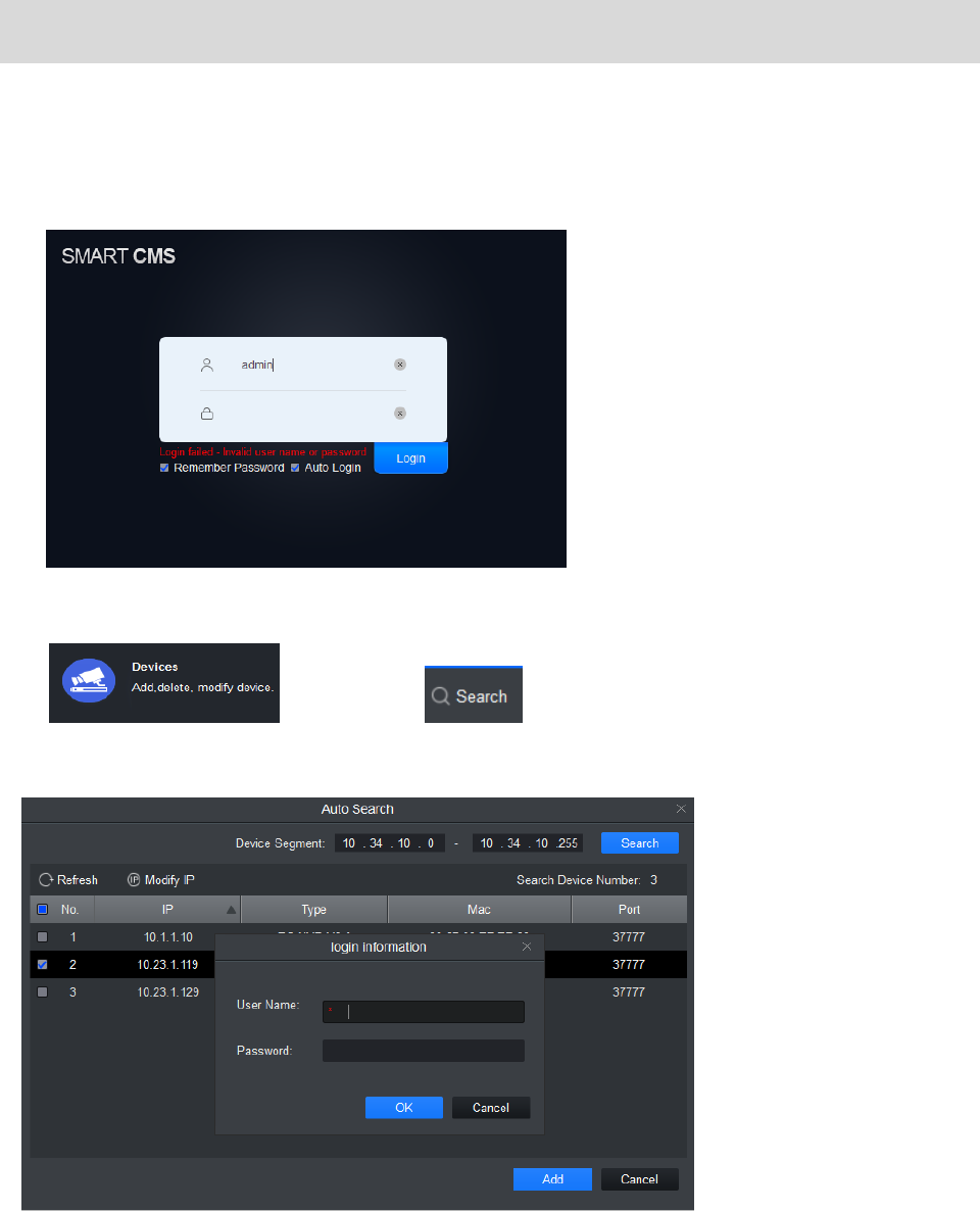
Double click the “smart cms.exe”,The user name and password are admin and admin .
Shown in Figure 4-1.
Figure 4-1
Step 3
Click , and then click to enter the interface where you can find IP
address.Shown in figure 4-2.
Input your username and password (Default username is admin and password is admin respectively).
Figure 4-2
12
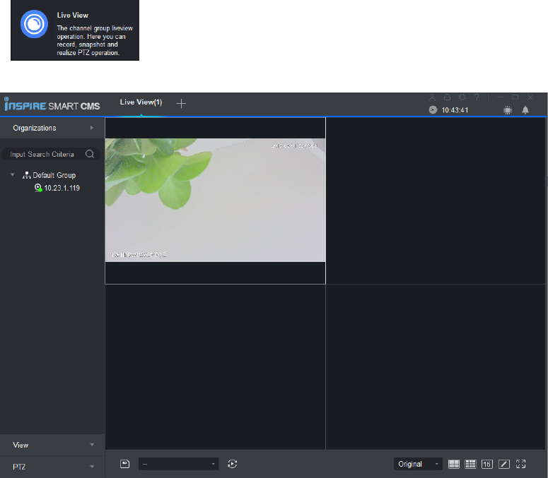
Step 4
Click ,and double click the default IP, See Error! Reference source not found. for
the main interface.
Error! Reference source not found.
13
5
55
5
Device Installation
Device Installation Device Installation
Device Installation
Important
Before the installation, please make sure the installation environment can at least support 3x weight of
the camera.
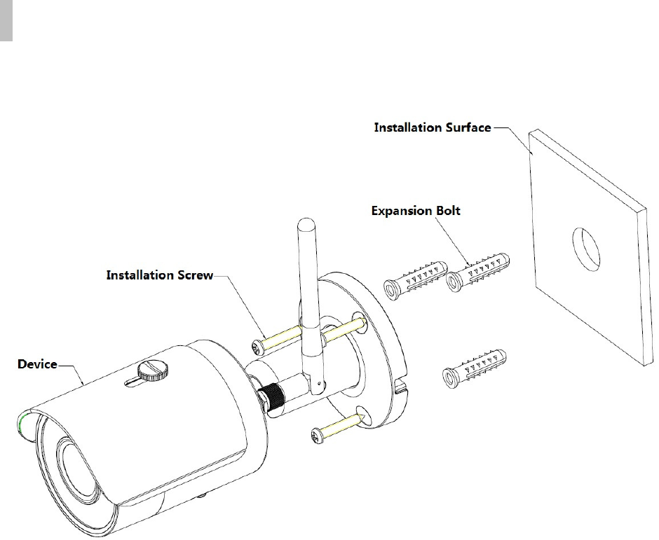
Figure 5-1
Please see Figure 5-1 and Figure 5-2.
Step 1
Dig holes on the installation surface (wall or ceiling).
Step 2
Open accessories bag, take out expansion bolt and insert it into the hole you just dug.
Step 3
Open accessories bag, take out installation screws. Tighten the screws to fix the device on the
installation surface (wall or ceiling). You can move device sunshade back and forth. When you have
fixed the device, you must tighten screws on sunshade.
Step 4
Plug external wiring of the device properly.
14
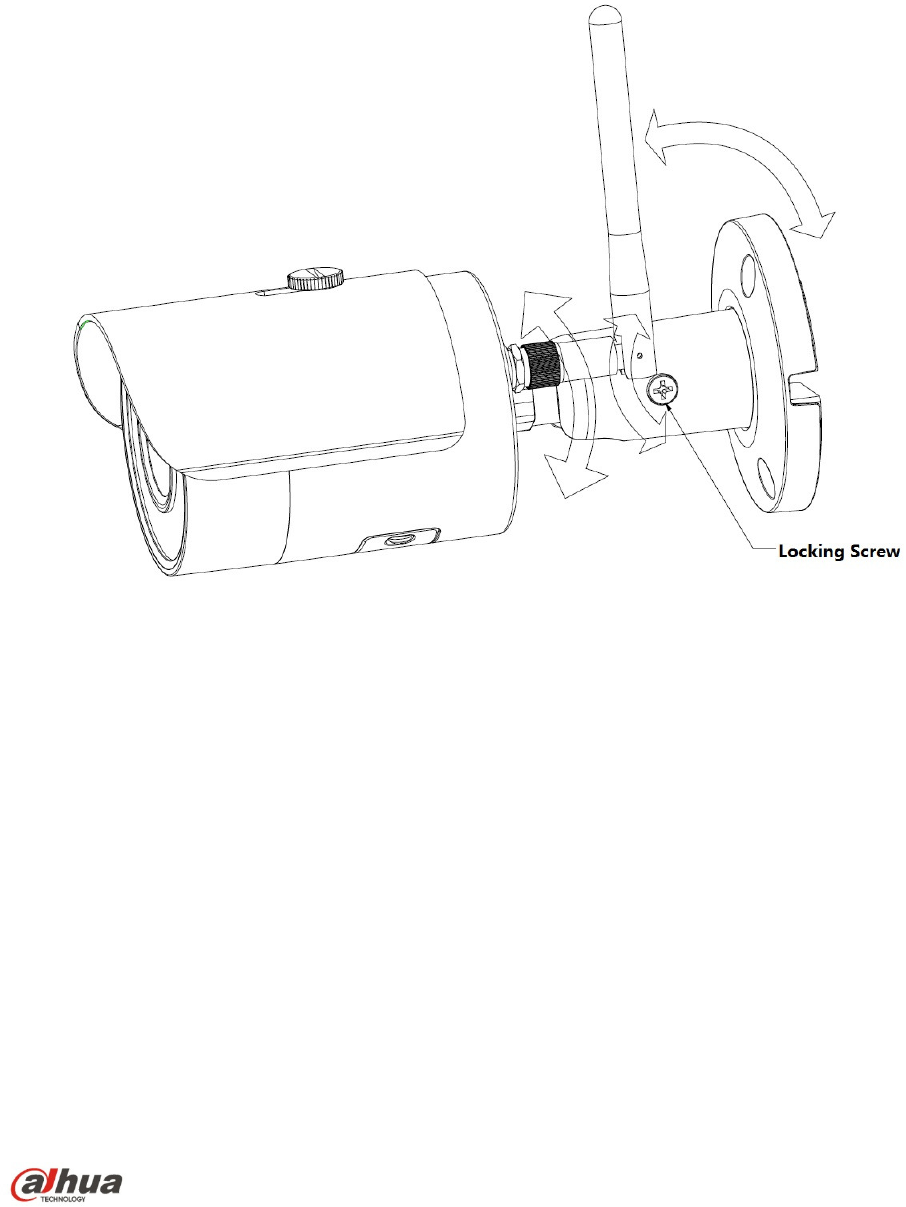
Figure 5-2
Step 5
Use cross screwdriver (in accessories bag) to loosen adjusting screw.
Step 6
Adjust the device in all possible directions, and set its monitoring direction according to the
requirements.
Step 7
Use cross screwdriver to tighten the adjusting screws.
Note:
This quick start guide is for reference only. Slight difference may be found in user interface.
All the designs and software here are subject to change without prior written notice.
All trademarks and registered trademarks mentioned are the properties of their respective
owners.
If there is any uncertainty or controversy, please refer to the final explanation of us.
Please visit our website or contact your local service engineer for more information.
Dahua Vision Technology Co., Ltd
Address:No.1199 Bin’an Road, Binjiang District, Hangzhou, PRC.
Postcode: 310053
Tel: +86-571-87688883
Fax: +86-571-87688815
Email:overseas@dahuatech.com
Website: www.dahuasecurity.com