Zhejiang Dahua Vision Technology IPC-KWABW IP Camera User Manual User 241 257s Manual
Zhejiang Dahua Vision Technology Co., Ltd IP Camera User 241 257s Manual
UserManual.wiki
>
Zhejiang Dahua Vision Technology
>
IPC KWABW User Manual
Manual
Navigation menu
Upload a User Manual
Namespaces
Wiki Guide
HTML
PDF
Info
Views
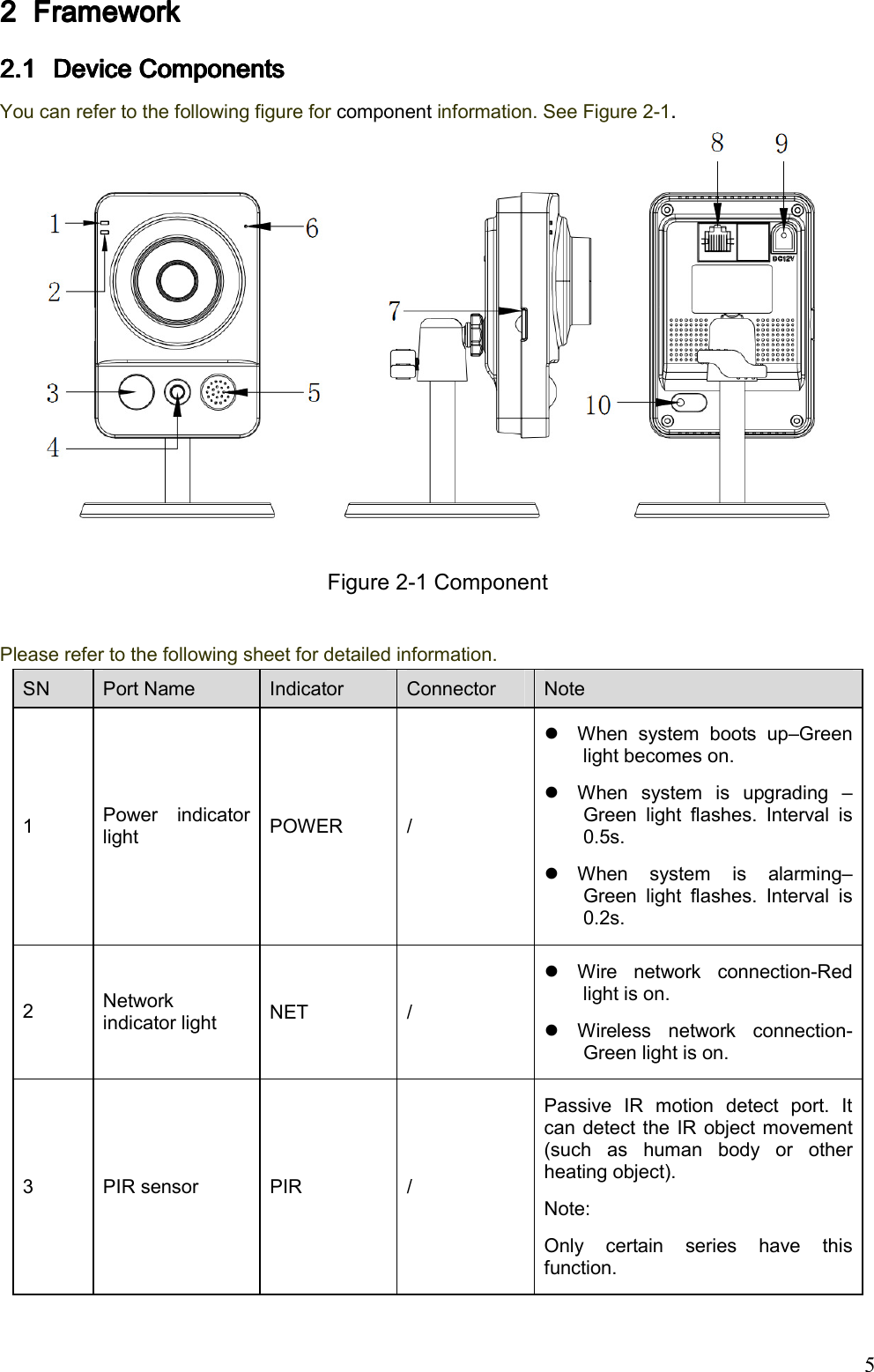
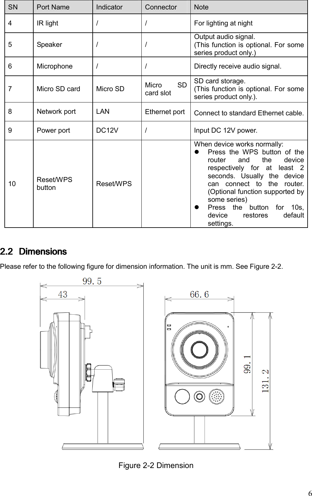
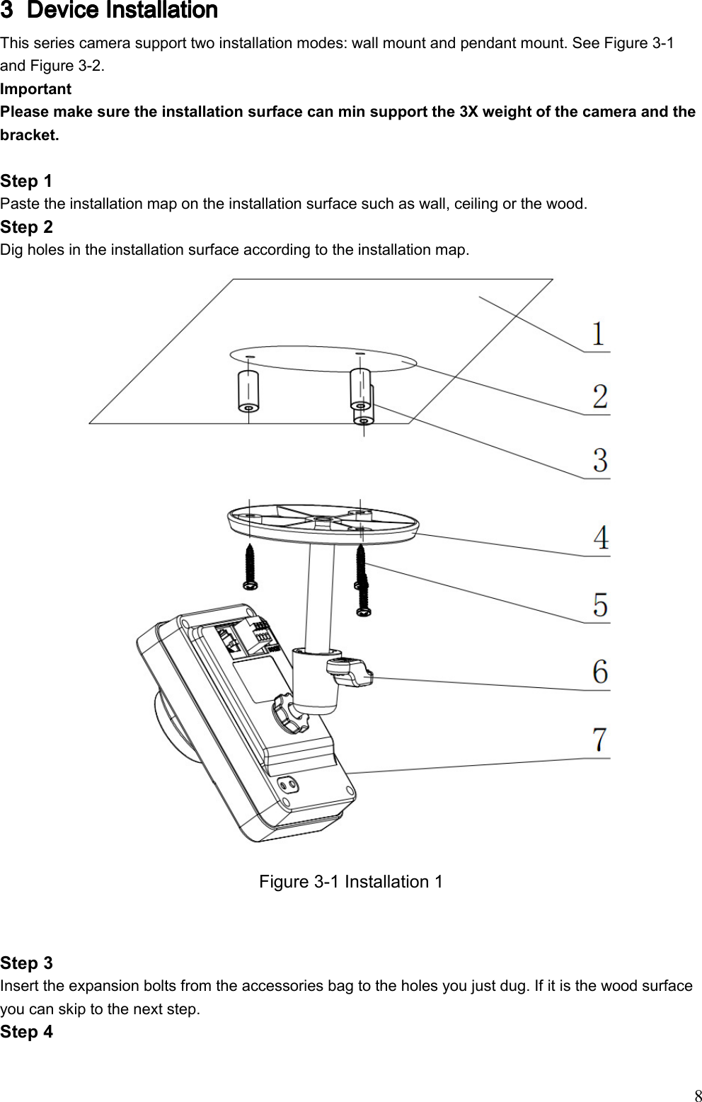
User Manual
Discussion / Help
Navigation