Zhejiang Dahua Vision Technology ITARD-024SA High Performance Narrow Beam Flat Radar User Manual K6 Camera User s manual
Zhejiang Dahua Vision Technology Co., Ltd High Performance Narrow Beam Flat Radar K6 Camera User s manual
Manual
ITARD-024SA
Radar
User’s Manual
Version 1.0.0
i
Table of Contents
1 General Introduction .................................................................................................................. 1
2 Features ....................................................................................................................................... 2
3 Specifications .............................................................................................................................. 3
4 Dimensions .................................................................................................................................. 4
5 Installation.................................................................................................................................... 5
6 FAQ .............................................................................................................................................. 8
Appendix Toxic or Hazardous Materials or Elements ................................................................. 9
FCC Warning………………………………………………………………………………………..10
ii
Welcome
Thank you for purchasing our device!
This user’s manual is designed to be a reference tool for your system.
Please read the following safeguard and warnings carefully before you use this series product!
Please keep this user’s manual well for future reference!
iii
Important Safeguards and Warnings
1.Electrical safety
All installation and operation here should conform to your local electrical safety codes.
The power shall conform to the requirement in the SELV (Safety Extra Low Voltage) and the Limited
power source is rated 12V DC (24V AC) in the IEC60950-1.
We assume no liability or responsibility for all the fires or electrical shock caused by improper handling
or installation.
2.Transportation security
Heavy stress, violent vibration or water splash are not allowed during transportation, storage and
installation.
3.Installation
Do not apply power to the radar before completing installation.
Always follow the instruction guide the manufacturer recommended.
4.Qualified engineers needed
All the examination and repair work should be done by the qualified service engineers.
We are not liable for any problems caused by unauthorized modifications or attempted repair.
5.Environment
The working temperature ranges from -30℃ to +70℃. Please keep it away from the electromagnetic
radiation object and environment.
Please keep the sound ventilation.
Do not allow the water and other liquid falling into the radar.
6. Accessories
Be sure to use all the accessories recommended by manufacturer.
Before installation, please open the package and check all the components are included.
Contact your local retailer ASAP if something is broken in your package.
1
1 General Introduction
ITARD-024SA is high-performance narrow-beam flat radar. It is an auxiliary product in the ITS
area of considerable integration and intelligent level. It is to detect the moving vehicle
dynamically to promote the modern management level of the road and city traffic.
ITARD-024SA realizes the vehicle detect via the Doppler effect theory. The radar sends out a ray
of microwave, and the microwave is reflected after it touched the moving vehicle. The radar can
receive the reflected wave. If the object has the radial movement relative to the radar, the
frequency of the reflected wave is different from the frequency of the send out wave. At the same
time, the difference of the frequency is proportion to the relative moving speed of the object and
the radar. Now the radar can detect the difference between the reflected wave and the send out
wave to calculate the moving speed of the vehicle.
The radar that used to detect the vehicle speed shall meet some basic requirements.
First, the antenna of the radar shall have sound direction capabilities. The wave beam shall not
be too wide. Otherwise, there are several lanes in the radar detect area at the same time; the
radar can not distinguish the object and can not calculate the speed. In the actual environments,
we can see the wave beam level width of the radar shall be less than 7°. The ITARD-024SA
adopts the 4.6°angle. To avoid the interference from the vehicle out of the beam, the side lobe
level of the antenna direction shall be general low. Usually it shall be less than -15dB. The
ITARD-024SA adopts -21.5 dB. At this value, it can effectively reduce the interference from the
neighboring lane. Besides, to accurately locate the vehicle position, the trailing edge of the radar
beam shall be steep, the typical and the wave beam-shape factor (-20dB width/-3dB width)
shall be less than 2.5.
The second requirement is speed measuring responsive time. It is the delay time from the object
enters the detect area to the radar gives the speed data. ITARD-024SA adopts the following
principles: for the vehicle of slow speed, the speed measuring responsive time is general long
and for the vehicle of high speed, the speed measuring responsive time is short. In this way, the
vehicles of all speeds are in the specified distance so that the camera can get the clear plate
information.
2
2 Features
Adopt flat micro beam array antenna design and manufacture technology. It can get the
commonness easily, light weight and high efficiency.
The speed measuring accuracy is high and the error ranges from -1km/h to +1km/h. High
reliability.
The level angle of the radar is small. In this way, it avoids the interference of reflected wave
from the neighboring lane.
Fast responsive time guarantees the capture rate and real-time feature.
Advanced radar signal process and data real-time process technology.
New algorithm, position is stable and the work can sustain.
It can be widely used in many environments, fully supports the 2nd development.
Low microwave radiation, low power consumption, long working hour, high stability and
reliability.

3
3 Specifications
Model
Spec
ITARD-024SA
Antenna Type
Flat micro beam array antenna
Radar
Mechanism
Single-frame continuous beam
Microwave
Working
Frequency
24.125GHz
50MHz
Send Power
9.5dBm=8.9mW
Antenna 3dB
Beam Width
4.6°(H) ×6.8°(V)
AD Sampling
Rate
25KHz
Working Mode
Approaching
Lane Amount
Single-lane
Detect Info
Speed(Instant)
Capture Rate
≥95%
Speed Measuring
Accuracy
±1Km/h
Speed Detect
Range
10-250Km/h
Communication
Interface
StandardRS-232
Cable Definition
Red:DC12V+ or AC24V1,Black:DC12V- or AC24V2,White:Tigger
Out,Yellow:RS232 RXD,Green:RS232 TXD,Orange:RS232 GND
Power Input
DC 12V/AC 24V
Current 500mA
Over voltage, over current, miss connection protection
Can supplying the power to the device safely and stably.
Power
Consumption
< 5W
Interface
Protection
There are over voltage and over current protection for all the corresponding
interfaces.
Working
Environments
Working temperature: -30℃~+70℃
Working humidity:10%~90%
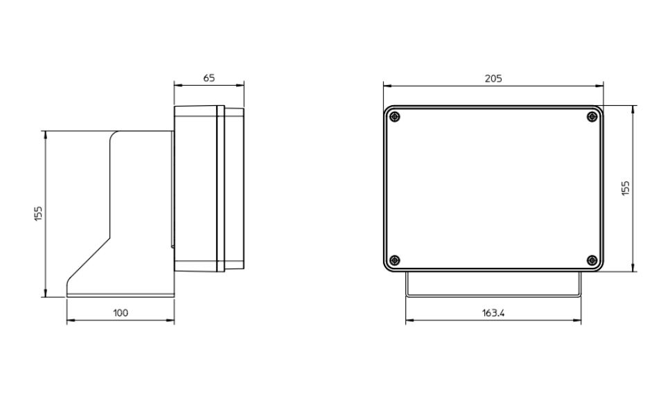
Dimensions(MM)
Radar:205mm*155mm*65mm
Bracket:163.4mm*100mm*155mm
Unit Weight
1kg(Excluding bracket)
5
5 Installation
ITARD-024SA high-performance narrow beam flat radar detect min speed is 10Km/h. It can not
directly provide the vehicle direction. The width of the microwave beam level and tilt is less than
3dB and usually it is used in the ANPR (Auto Number Plate Recognition).
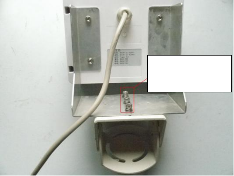
Step1
The radar shall be installed at the transverse arm (it is 5.5-7.5M height from the ground) at the
top of the lane. Please use three screws to fix the bracket and keep it standstill. See Figure 5-1.
Figure 5-1
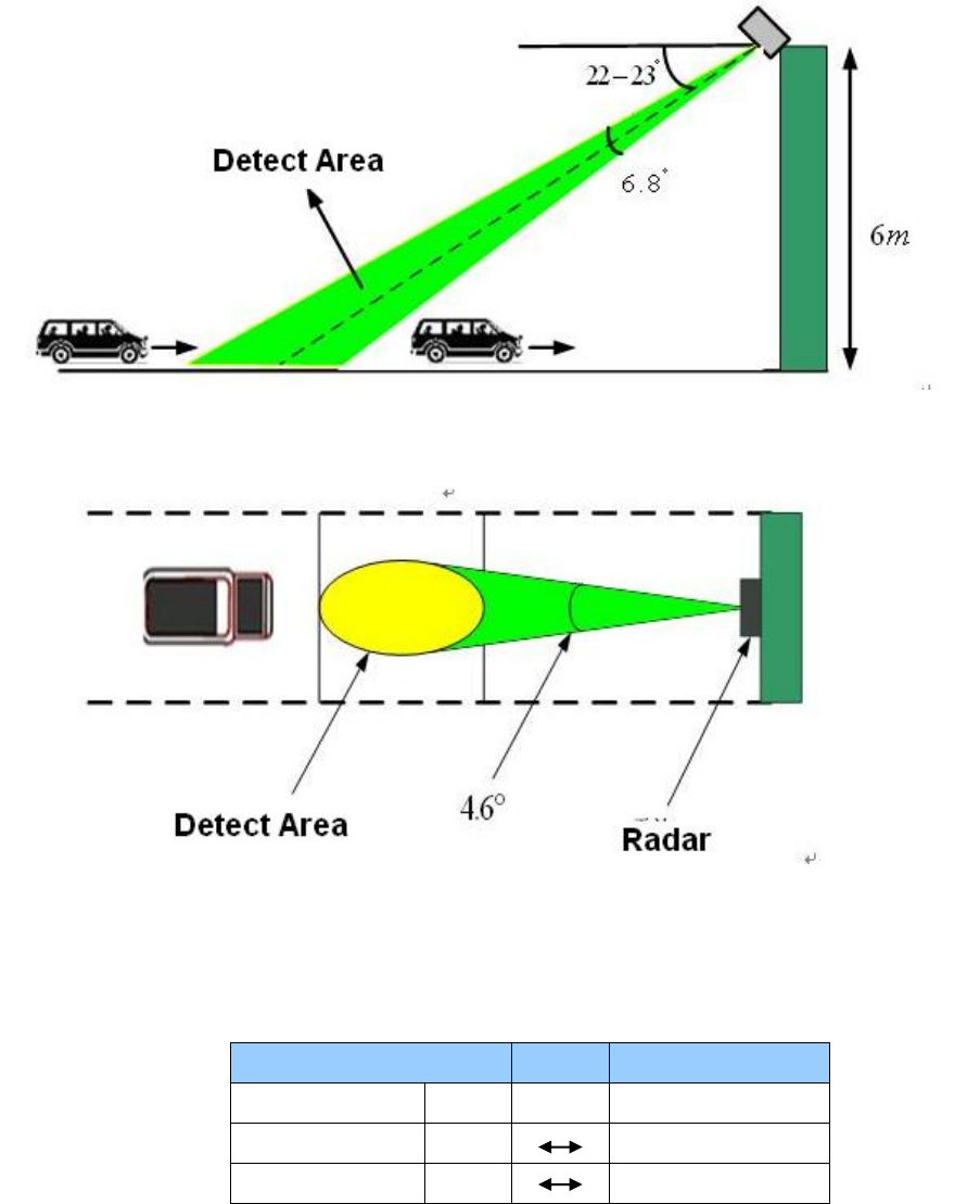
Step2
The antennae shall face the approaching vehicle. The radar wave beam shall have an angle with
the ground. Please adjust according to the project requirements and camera snap, usually the
distance from the centre of the radar monitor area to the projection ground distance of the radar
ranges from 10m to 20m.
Step3
Radar Installation Angle
For the environment of high traffic flow or strong wind, the recommend angle shall be 23°.It can
enhance the capture rate and performance is more stable. But the shortcoming is it can not snap
some vehicles that running on the traffic line and the vehicle snap position are about 15-17m.
If the traffic flow is low (such as the express road), the recommend angle shall be 22°.In this
situation, the capture rate may be lower than in the 23°, but the capture rate of the vehicles
running on the traffic line may be higher. At the same time, the snap position is general nearer. It
is about 16-18m. In this way, the camera can snap the human face.
Please secure these three
screws between the
pedestal and the bracket.
6
Please note the above angle is for reference only. Please select the reasonable snap position.
Usually, the nearer the distance is, it is easy to distinguish the vehicles one by one. But the
speed error correction value may be high, and vice versa. Besides, the radar wave beam level
width is fixed 3dB. It shall guarantee the single-lane (There is no interference form neighboring
lane) and at the same, it can capture the vehicle running on the line. It has requirements of the
radar beam level angle. When the projection distance is far, the width of the level 3dB shall be
smaller. When the projection distance is near, the width of the level 3dB shall be larger. When
the distance is fixed, the width of the level 3dB is high if the you want the lane becomes width.
The narrow the lane is, the width of the level 3dB is smaller.
Please refer to Figure 5-2 and Figure 5-3 for ANPR installation information.
Figure 5-2
Figure 5-3
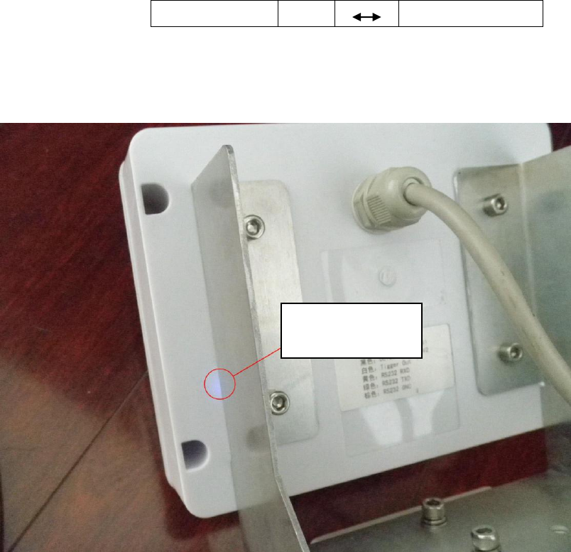
Step 4
Connect the radar to the camera.
Connect the radar to the camera via the RS232 port.
Radar
Camera
Cable Color
Signal
Signal
Green
TXD
RXD
Yellow
RXD
TXD

8
6 FAQ
Radar is a professional product of high technology and high sensitivity. Please read the user’s
manual carefully before you use.
Bug
Fix
There is no output, no
response, after I connected
the power to the device.
Check power connection and voltage
Check power positive end and the negative end connection
are right or not.
Check the communication cable connection is OK or not. The
cable connection SN is right or not.
Check the COM can get the applications properly or not.
Check application COM setup is OK or not.
I just got some disordered
code
Check the communication cable connection is OK or not. The
cable connection SN is right or not.
Make sure there is no strong interference on the
communication cable.
Check COM baud rate is OK or not.
There is no speed when a
vehicle passed.
Check the radar installation angle. Make sure it is facing the
corresponding lane.
The radar installation angle is within the reasonable range.
Check the distance from the radar to the object is in the
specified range.
The radar sensitivity is too low.
There is a speed but there is
no vehicle passing by.
There is strong electromagnetism interference or rotation
object.
Check the radar installation angle, whether there is
interference from the neighboring lane.
The radar sensitivity is too high.
It missed vehicle
Check the radar installation angle. Make sure it is facing the
corresponding lane.
Check the distance from the radar to the object is in the
specified range,.
The radar sensitivity is too low.
The camera does not snap
Check the communication cable connection is OK or not. The
cable connection SN is right or not.
Check camera protocol is right or not.
Check the RS232 setup; make sure the baud rate setup is
right.
The camera snap function is enabled.
The radar working mode such as min object interval, detect
direction, sensitivity is right.

9
Appendix Toxic or Hazardous Materials or Elements
Component
Name
Toxic or Hazardous Materials or Elements
Pb
Hg
Cd
Cr VI
PBB
PBDE
Circuit Board
Component
○
○
○
○
○
○
Device
Construction
Material
○
○
○
○
○
○
Wire and
Cable/AC
Adapter
○
○
○
○
○
○
Packing
Components
/Accessories
○
○
○
○
○
○
O: Indicates that the concentration of the hazardous substance in all homogeneous materials in
the parts is below the relevant threshold of the SJ/T11363-2006 standard.
X: Indicates that the concentration of the hazardous substance of at least one of all
homogeneous materials in the parts is above the relevant threshold of the SJ/T11363-2006
standard.
Note
This manual is for reference only. Slight difference may be found in the user
interface.
All the designs and software here are subject to change without prior written
notice.
All trademarks and registered trademarks are the properties of their respective
owners.
If there is any uncertainty or controversy, please refer to the final explanation of us.
Please visit our website or contact your local service engineer for more
information.
10
FCC Warning
This device complies with Part 15 of the FCC Rules. Operation is subject to the following two
conditions: (1) this device may not cause harmful interference, and (2) this device must accept
any interferencereceived, including interference that may cause undesired operation.
CAUTION: changes or modifications not expressly app roved by the party responsible for
compliance could void the user's authority to operate the equipment.
For a Class B digital device or peripheral, the instructions furnished the user shall include the
following or similar statement, placed in a prominent location in the text of the manual:
NOTE: This equipment has been tested and found to comply with the limits for a Class B digital
device, pursuant to Part 15 of the FCC Rules. These limits are designed to provide reasonable
protection against harmful interference in a residential installation. This equipment generates,
uses and can radiate radio frequency energy and, if not installed and used in accordance with
the instructions, may cause harmful interference to radio communications.However, there
is no guarantee that interference will not occur in a particular installation. If this equipment does
cause harmful interference to radio or television reception, which can be determined by turning
the equipment off and on, the user is encouraged to try to correct the interference by one or more
of the following measures:
-- Reorient or relocate the receiving antenna.
-- Increase the separation between the equipment and receiver.
-- Connect the equipment into an outlet on a circuit differentfrom that to which the receiver is
connected.
-- Consult the dealer or an experienced radio/TV technician for help