Zhejiang Dahua Vision Technology SD29 INCH IR PTZ DOME CAMERA User Manual F4X5 Indoor Series Network Camera User s Manual
Zhejiang Dahua Vision Technology Co., Ltd INCH IR PTZ DOME CAMERA F4X5 Indoor Series Network Camera User s Manual
User manual
i
Network Speed Dome & PTZ Camera
Web3.0 Operation Manual
Version 1.0.0
ii
Table of Contents
1 Network Config .............................................................................................................. 1
1.1 Network Connection .......................................................................................... 1
1.1 Log in WEB Interface ........................................................................................ 2
1.1.1 Device Initialization ..................................................................................... 2
1.1.2 Device Login ............................................................................................... 5
1.1.3 Forget Password......................................................................................... 5
2 Live ................................................................................................................................ 8
2.1 Encode Setup ................................................................................................... 8
2.2 Video Window Adjustment ................................................................................ 9
2.3 System Menu .................................................................................................. 12
2.4 Video Window Function Option ....................................................................... 12
2.5 PTZ Config ...................................................................................................... 13
3 Playback ...................................................................................................................... 18
3.1 Video Playback ............................................................................................... 18
3.1.1 Play Function ............................................................................................ 19
3.1.2 Record Type ............................................................................................. 20
3.1.3 Assistant Function .................................................................................... 20
3.1.4 Playback File ............................................................................................ 21
3.1.5 Playback Clip ............................................................................................ 24
3.1.6 Progress Bar Time Format ....................................................................... 25
3.2 Picture Playback ............................................................................................. 25
3.2.1 Play Function ............................................................................................ 26
3.2.2 Playback File ............................................................................................ 26
3.2.3 Snapshot Type ......................................................................................... 27
4 Setup ........................................................................................................................... 28
4.1 Camera ........................................................................................................... 28
4.1.1 Conditions ................................................................................................. 28
4.1.2 Video ........................................................................................................ 45
4.1.3 Audio ........................................................................................................ 53
4.2 Network ........................................................................................................... 55
4.2.1 TCP/IP ...................................................................................................... 55
4.2.2 Port ........................................................................................................... 59
4.2.3 PPPoE ...................................................................................................... 61
4.2.4 DDNS ....................................................................................................... 62
4.2.5 IP filter ...................................................................................................... 66
4.2.6 SMTP (e-mail) ........................................................................................ 67
iii
4.2.7 UPnP ........................................................................................................ 69
4.2.8 SNMP ....................................................................................................... 70
4.2.9 Bonjour ..................................................................................................... 73
4.2.10 Multicast ................................................................................................... 74
4.2.11 802.1x ....................................................................................................... 74
4.2.12 QoS .......................................................................................................... 75
4.2.13 HTTPs ...................................................................................................... 76
4.3 PTZ Setting ..................................................................................................... 89
4.3.1 Protocol .................................................................................................... 89
4.3.2 Function .................................................................................................... 90
4.4 FCC Compliance Statement ………………………………………………………...102
Important
The following functions are for reference only. Some series products may not
support all the functions listed below.

iv
Cybersecurity Recommendations
Cybersecurity Recommendations
Mandatory actions to be taken towards cybersecurity
1. Change Passwords and Use Strong Passwords:
The number one reason systems get “hacked” is due to having weak or default passwords. It is
recommended to change default passwords immediately and choose a strong password whenever

v
possible. A strong password should be made up of at least 8 characters and a combination of special
characters, numbers, and upper and lower case letters.
2. Update Firmware
As is standard procedure in the tech-industry, we recommend keeping NVR, DVR, and IP camera
firmware up-to-date to ensure the system is current with the latest security patches and fixes.
“Nice to have” recommendations to improve your network security
1. Change Passwords Regularly
Regularly change the credentials to your devices to help ensure that only authorized users are able to
access the system.
2. Change Default HTTP and TCP Ports:
Change default HTTP and TCP ports for systems. These are the two ports used to communicate
and to view video feeds remotely.
These ports can be changed to any set of numbers between 1025-65535. Avoiding the default
ports reduces the risk of outsiders being able to guess which ports you are using.
3. Enable HTTPS/SSL:
Set up an SSL Certificate to enable HTTPS. This will encrypt all communication between your devices
and recorder.
4. Enable IP Filter:
Enabling your IP filter will prevent everyone, except those with specified IP addresses, from accessing
the system.
5. Change ONVIF Password:
On older IP Camera firmware, the ONVIF password does not change when you change the system’s
credentials. You will need to either update the camera’s firmware to the latest revision or manually
change the ONVIF password.
6. Forward Only Ports You Need:
Only forward the HTTP and TCP ports that you need to use. Do not forward a huge range of
numbers to the device. Do not DMZ the device's IP address.
You do not need to forward any ports for individual cameras if they are all connected to a recorder
on site; just the NVR is needed.

vi
7. Disable Auto-Login on SmartPSS:
Those using SmartPSS to view their system and on a computer that is used by multiple people should
disable auto-login. This adds a layer of security to prevent users without the appropriate credentials
from accessing the system.
8. Use a Different Username and Password for SmartPSS:
In the event that your social media, bank, email, etc. account is compromised, you would not want
someone collecting those passwords and trying them out on your video surveillance system. Using a
different username and password for your security system will make it more difficult for someone to
guess their way into your system.
9. Limit Features of Guest Accounts:
If your system is set up for multiple users, ensure that each user only has rights to features and
functions they need to use to perform their job.
10. UPnP:
UPnP will automatically try to forward ports in your router or modem. Normally this would be a good
thing. However, if your system automatically forwards the ports and you leave the credentials
defaulted, you may end up with unwanted visitors.
If you manually forwarded the HTTP and TCP ports in your router/modem, this feature should be
turned off regardless. Disabling UPnP is recommended when the function is not used in real
applications.
11. SNMP:
Disable SNMP if you are not using it. If you are using SNMP, you should do so only temporarily, for
tracing and testing purposes only.
12. Multicast:
Multicast is used to share video streams between two recorders. Currently there are no known issues
involving Multicast, but if you are not using this feature, deactivation can enhance your network security.
13. Check the Log:
If you suspect that someone has gained unauthorized access to your system, you can check the system
log. The system log will show you which IP addresses were used to login to your system and what was
accessed.

vii
14. Physically Lock Down the Device:
Ideally, you want to prevent any unauthorized physical access to your system. The best way to achieve
this is to install the recorder in a lockbox, locking server rack, or in a room that is behind a lock and key.
15. Connect IP Cameras to the PoE Ports on the Back of an NVR:
Cameras connected to the PoE ports on the back of an NVR are isolated from the outside world and
cannot be accessed directly.
16. Isolate NVR and IP Camera Network
The network your NVR and IP camera resides on should not be the same network as your public
computer network. This will prevent any visitors or unwanted guests from getting access to the same
network the security system needs in order to function properly.
1
1 Network Config
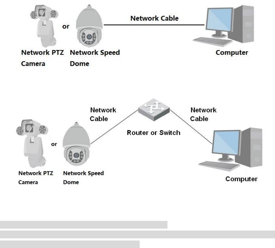
1.1 Network Connection
There are mainly two connection modes between network speed dome and PC. See Figure 1-1 and
Figure 1-2.
Figure 1-1
Figure 1-2
Note:
The models presented in the figure are for reference only.
In order to describe operation steps more conveniently, both network speed dome and network
PTZ camera will be called “Camera” hereinafter.
The IP address of all the intelligent speed domes is 192.168.1.108 by default when they are delivered
out of factory; it needs to plan available IP segment reasonably according to practical network
environment in order to make intelligent speed domes get access to network smoothly. Users can
modify IP address via quick config tool in the disk, please refer to <<Quick Configuration Tool User
manual>> for more details.
2
1.1 Log in WEB Interface
1.1.1 Device Initialization
It needs to implement initialization upon the device if it is used for the first time; the steps are shown as
follows:
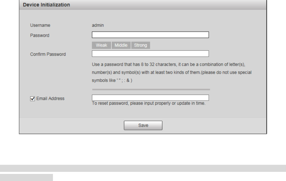
Step 1
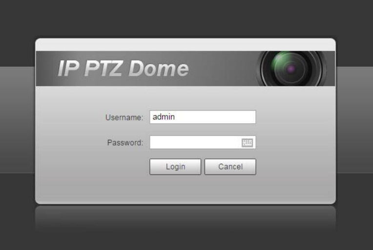
Open IE browser, input IP address of network speed dome in the address bar and press Enter button.
The system will display the interface which is shown in Figure 1-3 after it is successfully connected.
Figure 1-3
Note
Email address function is enabled by default; you can select to disable the function according to the
actual requirement.
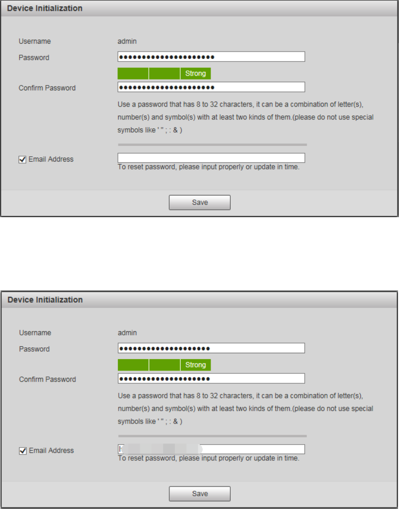
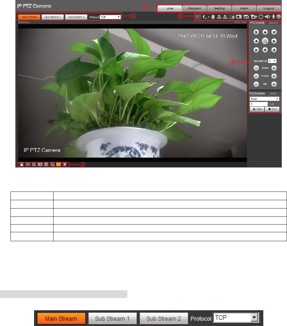
Step 2
It is to set the password of admin user.
The config interface is shown in Figure 1-4.
Note
The password can be set as 8 to 32 nonblank characters, which can be made up of upper case, lower
case, number and special character (except “'”,“"”,“;”,“:”and“&”), and it has to contain at
least two types of characters. Make sure the new password is in accordance with the confirm password.
Please set the password with high security according to the password intensity prompt.
4
Figure 1-6
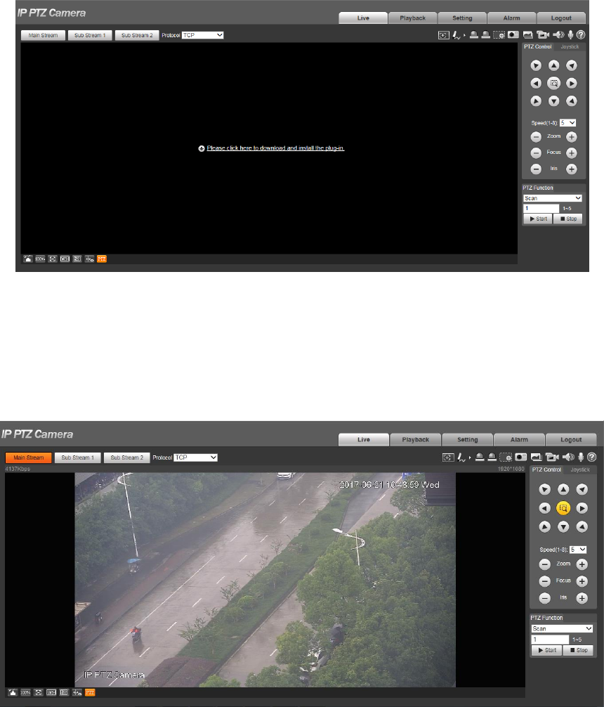
Step 5
Install or load plug-in according to the system prompt.
The plug-in installation interface will be closed automatically after plug-in installation is completed, the
WEB client will refresh automatically and it will generate the video interface shown in Figure 1-7.
Figure 1-7
Note
The interface above is for references only, please refer to the actual device for more details.
5
1.1.2 Device Login
Step 1
Open IE browser and input IP address of network speed dome in the address bar, then press “Enter”. It
will display the interface shown in Figure 1-8 after it is successfully connected.
Figure 1-8
Step 2
Please input your username and password, and then click “Login” to enter WEB operation interface.
Note
The device will be locked for 5 minutes if it inputs wrong password continuously for 5 times. It can
log in device again after lock time is over.
Step 3
It is to install or load plug-in according to system prompt after it logs in successfully. The plug-in
installation interface will be closed automatically after plug-in installation is completed, the WEB
client will refresh automatically and video will show up in the monitoring image.
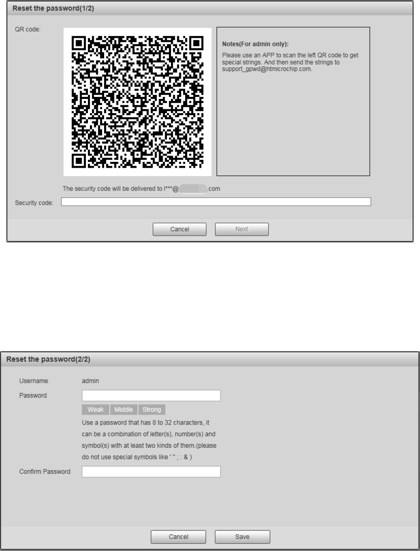
1.1.3 Forget Password
Step 1
Click “Forget Password” and the system will display the interface of “Reset Password”, which is
shown in Figure 1-9.
7
Step 4
Set the password of admin user again.
Step 5
Click “Save” to complete setting.
8
2 Live
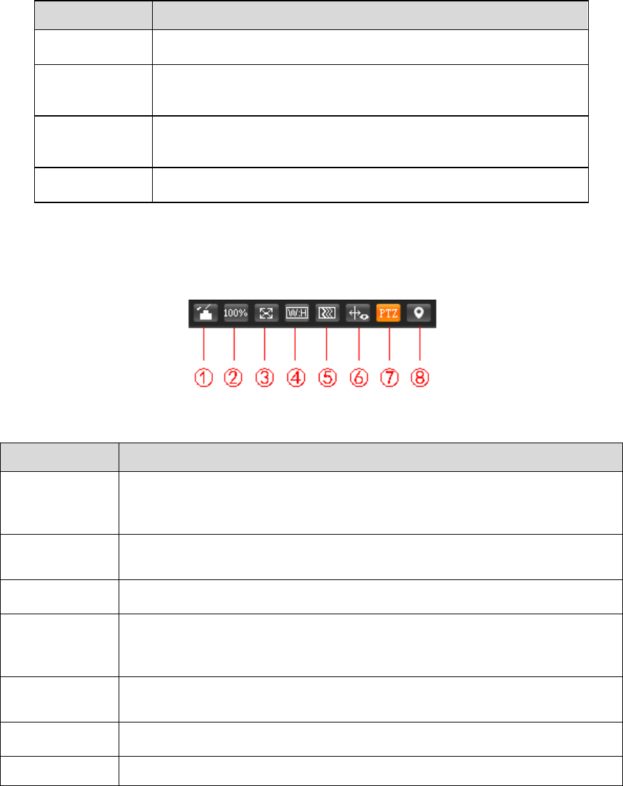
Users can implement several operations on the “Live” interface upon the real-time monitoring image,
such as live, snapshot, record and etc.; you can also implement simple PTZ operation.
Click “Live” to display “Live” interface which is shown in Figure 2-1.
Figure 2-1
SN
Note
①
Encode setting column
②
Video window adjust column
③
System menu column
④
Video window function option column
⑤
PTZ config column
Table 2-1
2.1 Encode Setup
Note
Some models don’t support two sub streams
The encode setup interface is shown as in Figure 2-2.
9
Figure 2-2
Please refer to Table 2-2 for detailed information.
Parameter
Function
Main stream
Streaming media protocol connection, under main stream config,
monitor video or not. Generally for storage and monitor.
Sub (Extra)
stream 1
Streaming media protocol connection, under sub stream 1
config, monitor video or not. When network bandwidth is
insufficient, it substitutes main stream for monitoring.
Sub (Extra)
stream 2
Streaming media protocol connection, under sub stream 2
config, monitor video or not. When network bandwidth is
insufficient, it substitutes main stream for monitoring.
Protocol
You can select stream media protocol from the dropdown list.
There are three options: TCP/UDP/Multicast
Table 2-2
2.2 Video Window Adjustment
Figure 2-3
Parameter
Note
1. Image
Adjustment
Click “Image Adjustment” and it will display image adjustment interface on
the right of the live interface, then you can adjust image brightness,
contrast and etc.
2. Original
Size
Click the button and it will display the actual size of video stream.
3. Full Screen
Click it to go to full-screen mode. Double click the mouse or click the Esc
button to exit the full screen.
4. Width and
Height
Ratio
Click it to adjust image to original ratio or suitable window.
5. Fluency
Adjustment
There are three levels of fluency for you to select (real-time, normal,
fluent). The default is normal.
6. Rules Info
Click it to enable preview page to display intelligent rules, the default is
enabled.
7. PTZ
Click it to enable live page to display PTZ config item.
10
Parameter
Note
8. Panorama
PTZ
Click the button to display panorama window in the live interface, it can
realize quick position, call preset, tour and other operations in the window.
Table 2-3
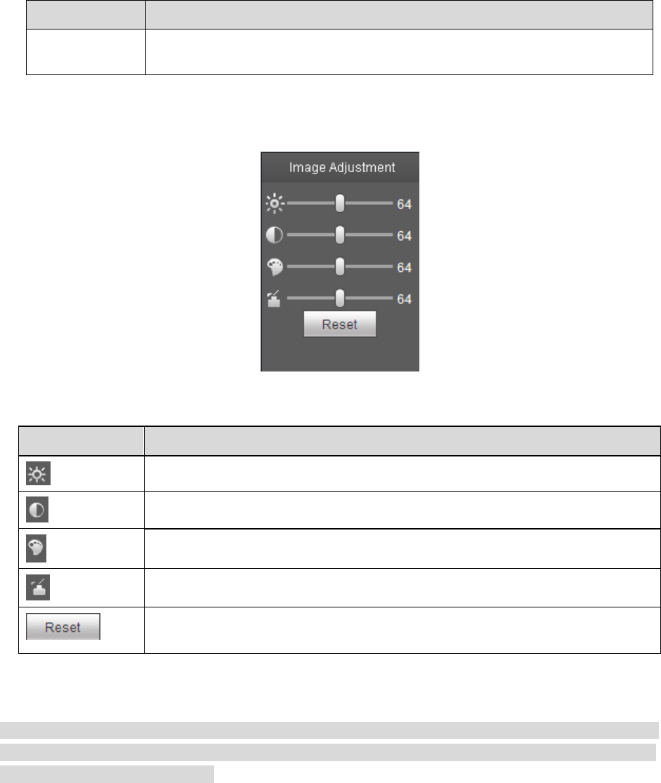
Image Adjustment
Figure 2-4
Parameter
Note
It is to adjust monitoring image brightness.
It is to adjust monitoring image contrast.
It is to adjust monitoring image hue.
It is to adjust monitoring image saturation.
Restore brightness, contrastness, saturation and hue to system default
setup.
Table 2-4
Note
The function can only be used to adjust the brightness, contrast, hue and saturation of the monitoring
image in WEB client. It needs to go to “Setup > Camera > Conditions” to set the brightness, contrast,
hue and saturation of the device.
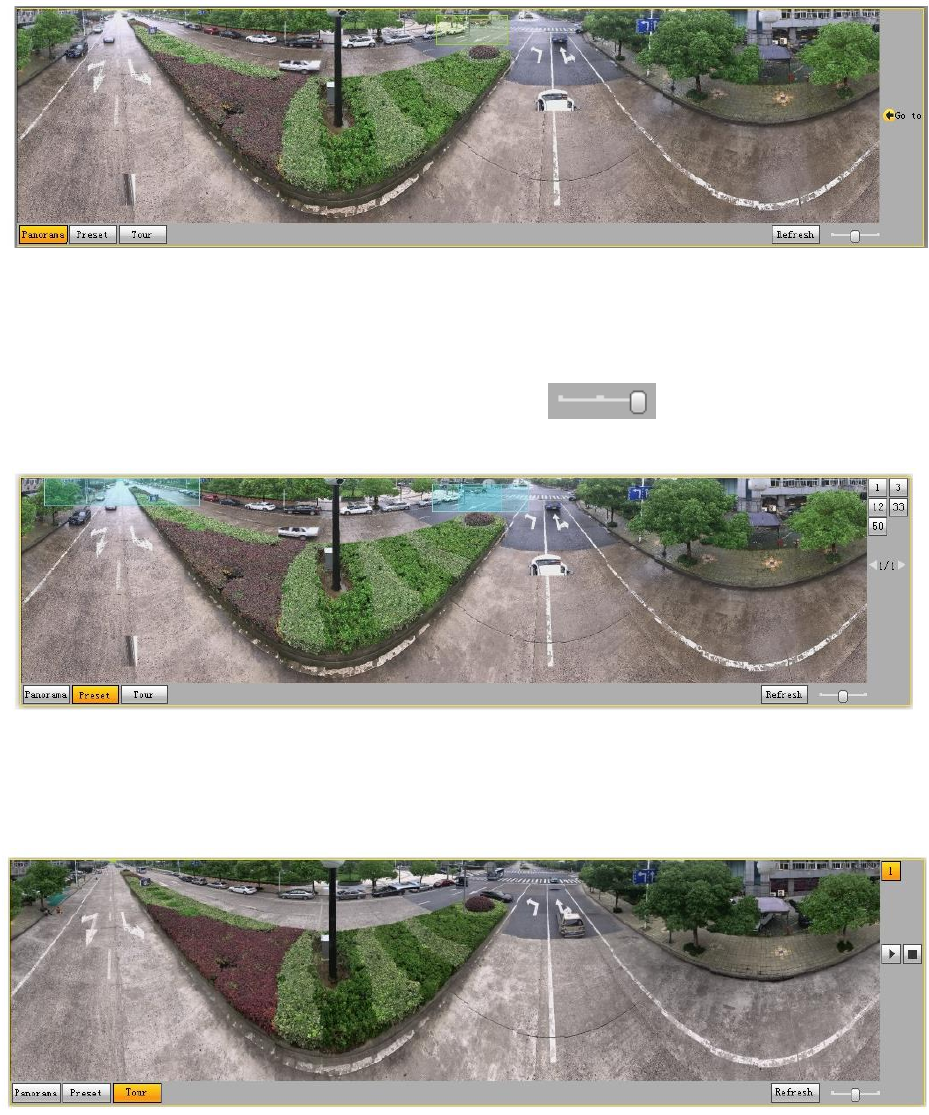
Panorama PTZ
11
Figure 2-5
Use left mouse button to draw a box to operate positioning in the window, the live page will display the
positioned location and zoom in. Click “Refresh”, and the camera will rotate horizontal 0°~360°, vertical
6°~75°to regain panorama image. Drag the picture ratio bar to adjust the size of panorama
picture.
Figure 2-6
User can use the corresponding preset on the right of the window, please refer to “3.3.2.1 Preset” for
more details about preset setting.
Figure 2-7
12
User can use the corresponding tour on the right of the window, please refer to “3.3.2.2 Tour” for more
details about tour setting.
2.3 System Menu
Click each item to enter corresponding interface.
Figure 2-8
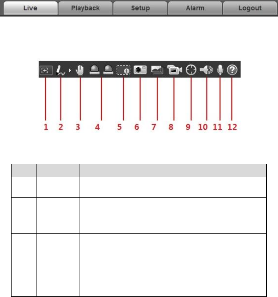
2.4 Video Window Function Option
Figure 2-9
Please refer to the following sheet for detailed information.
SN
Parameter
Function
1
Regional
focus
Click it and use mouse to select any area in the video image,
and it can make the device auto focus in the selected area.
2
Remark
Click it and then select pen color, you can write down the
mark information on the preview interface.
3
Gesture
Control
Click it and control the PTZ via dragging left mouse button in
the preview interface, mouse roller can control zoom rate.
4
Relay out
Click the button to trigger alarm. The light becomes red/gray
when there is relay out/cancel.
5
Digital
Zoom
When the video is in the original status, click it you can
select any zone to zoom in. In the non-original status,
you can drag the zoom-in zone in specified range. Right
click mouse to restore previous status.
Click it; you can use the middle button of the mouse to
zoom in/out the video size.

13
6
Snapshot
Click the button to snapshot, save picture to path in Chapter
3.1.2.5
7
Triple snap
Click it, system can snap at 1f/s. All images are saved to path
in Chapter 3.1.2.5.
8
Record
Click it, system can record. All images are saved to path in
Chapter 3.1.2.5.
9
Manual
track
Click the button and then drag left mouse button to select any
area in the video window, the speed dome will make smart
tracking to the object in the area.
Note: It needs to check “Event >IVS Plan> Rule
Config>Smart Track”, otherwise, it will be invalid.
10
Audio
output
Turn on or off audio when you are monitoring.
11
Talk
Click it to start or end bidirectional talk.
12
Help
Click it to open help file.
Table 2-5
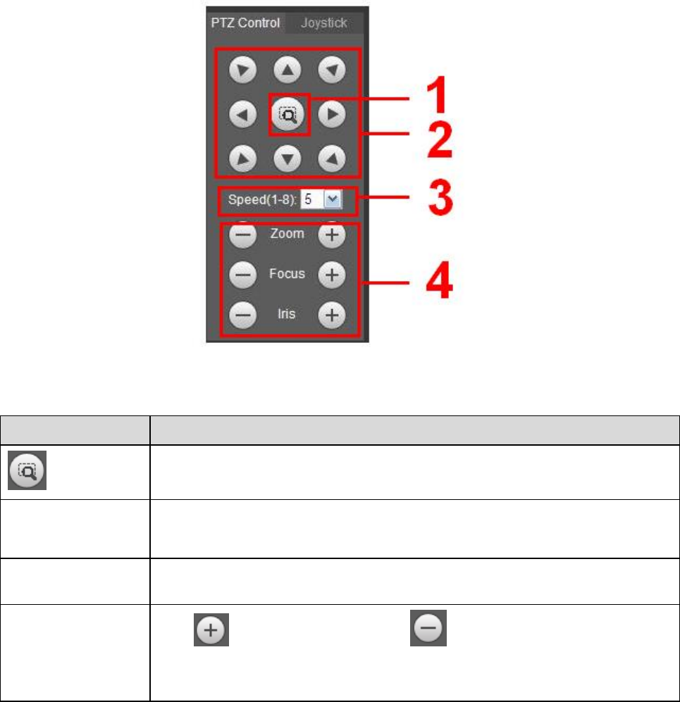
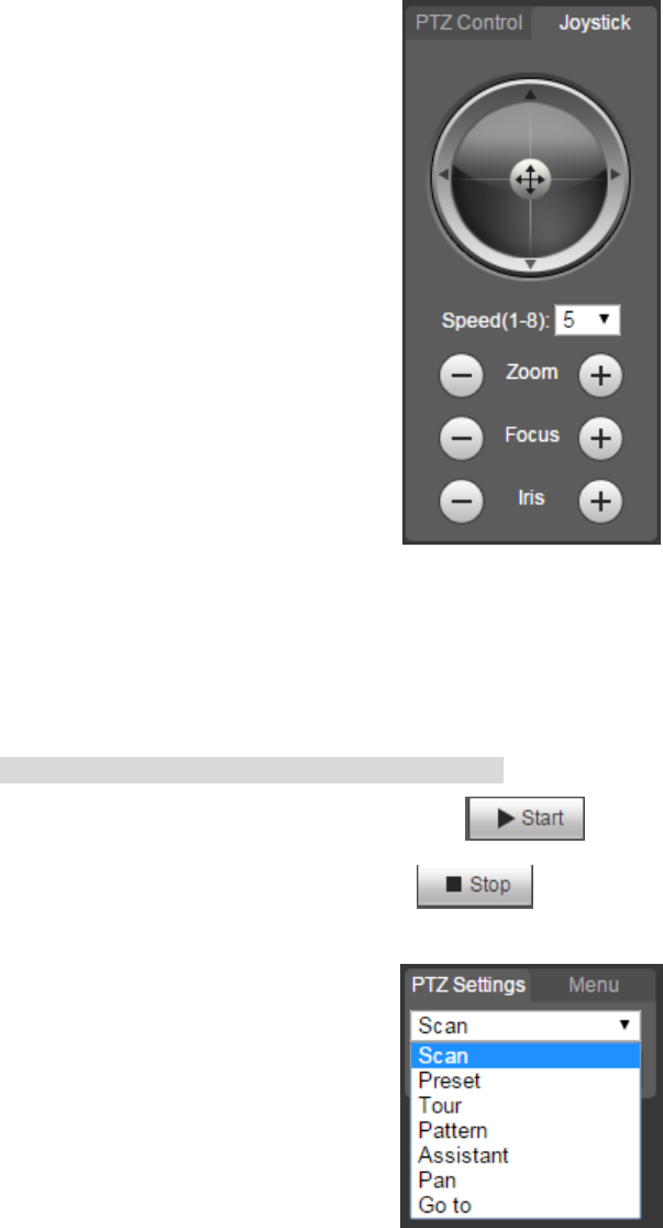
2.5 PTZ Config
You can control PTZ via PTZ control or virtual joystick; also you can enable the functions of preset, scan
and etc. in the PTZ setting area.
PTZ Control
Note
Users have to set PTZ protocol first before using PTZ control, please refer to “Setup > PTZ Settings >
Protocol” for more details.
Please refer to Figure 2-10 for the interface of PTZ control, refer to Table 2-6 for more details about
parameters.
14
Figure 2-10
Parameter
Note
Quick Position
Use mouse to draw a box in monitoring video, PTZ will rotate, focus and
quickly position the scene.
PTZ direction
PTZ supports eight directions: left/right/up/down/upper left/upper right/bottom
left/bottom right.
Speed
It controls rotation speed. The longer the step length, the higher the speed.
Step length control PTZ, zoom, focus and iris.
Zoom/focus/iris
Click to increase value and click to decrease value.
Note:
Some cameras don’t support iris, please refer to the actual devices for details.
Table 2-6
Virtual Joystick
The virtual joystick interface is shown as below. See Figure 2-11.
This function allows you to control the button in then center to simulate the joystick operation. You can
use it to control device movement.
15
Figure 2-11
The setting method of speed, zoom, focus and iris is the same as that of the PTZ control.
PTZ Setting
Note
Please refer to “4.3 PTZ Setting” for more details.
The PTZ can support various functions. Click to start some certain PTZ function, and at this
moment the “Start/Stop” button becomes , click the button to stop the PTZ function. The
config interface is shown in Figure 2-12; please refer to Table 2-7 for more details about each function.
Figure 2-12
Please refer to the following sheet for PTZ setup information.
16
Parameter
Function
Scan
Select Scan from the dropdown list, click Start button, you can begin
scan operation. Default SN is 1.
Preset
Input the preset value and then click View button, the camera turns
to the corresponding position of the preset.
Tour
Select Tour from the dropdown list and then click Start button, you
can begin tour.
Pattern
You can select Pattern from the dropdown list and then click Start
button to begin PTZ movement.
Assistant
Reserve extended function, it can support special requirements.
Note
It is recommended to enable the function with the guidance of
professional staff if necessary; otherwise it may cause some
unexpected problems.
Pan
Select Pan from the dropdown list and then click “Start” button and it
can realize horizontal rotation of the PTZ.
Wiper
Select wiper, click “Open” to enable wiper function; click “Close” to
disable wiper function.
Go to
It is the accurate positioning function. Please input
corresponding horizontal angle, vertical angle and zoom speed
and then click “Go to” button to go to a specified position.
One unit of the horizontal angle or vertical angle stands for 0.1
degree.
Table 2-7
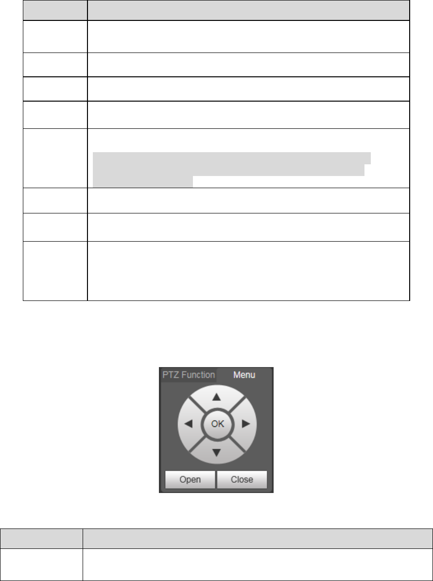
Menu
The menu interface is shown in Figure 2-13; please refer to Table 2-8 for more details about parameters.
Figure 2-13
Parameter
Note
Direction button
Up and down buttons are used to select parameters, left and right buttons
are used to select parameter value.
17
Parameter
Note
OK
Click it to confirm.
Open
Open OSD menu.
Close
Click it to close menu.
Table 2-8
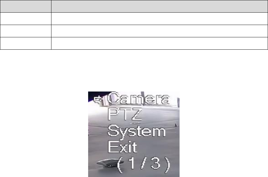
Click Open to enable menu function, then you can see the OSD menu in the monitoring image, which is
shown in Figure 2-14.
Figure 2-14
Here you can set the following items:
Camera: please refer to “4.1.1 Camera Condition”.
PTZ: please refer to “4.3 PTZ setting”.
System: Please refer to “Error! Reference source not found. System”.
Users can modify the location of OSD menu in “4.1.2.3 Video Overlay”.
18
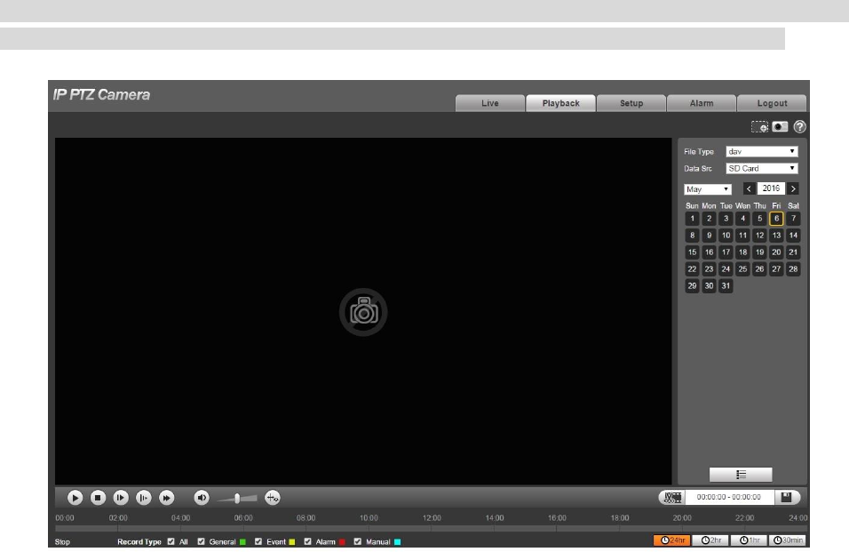
3 Playback
You can playback the saved video or picture in the “Playback” interface.
Note
It needs to set record, snapshot period, storage method, record control and other parameters in “Error!
Reference source not found. Storage Management” before implementing playback operation.
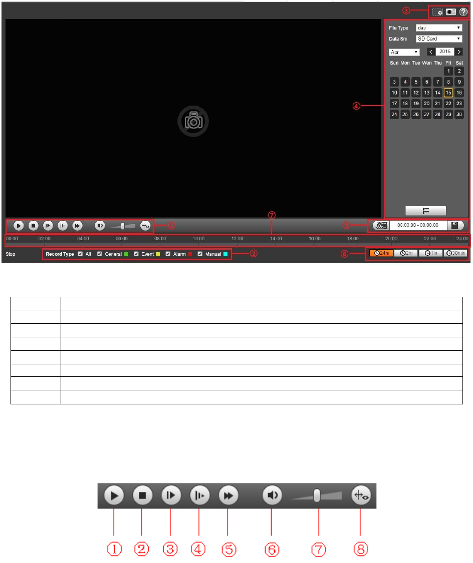
Click “Playback” item, and the system will display “Playback” interface, which is shown in Figure 3-1.
Figure 3-1
3.1 Video Playback
Select file type as “dav” and the system will display the interface which is shown in Figure 3-2. Refer to
Table 3-1 for more details about parameters.
19
Figure 3-2
SN
Note
1
Play function column
2
Record type column
3
Assistant function column
4
Playback file column
5
Playback clip column
6
Progress bar time format column
7
Progress bar
Table 3-1
3.1.1 Play Function
Play function column is shown in Figure 3-3, refer to Table 3-2 for more details about parameters.
Figure 3-3
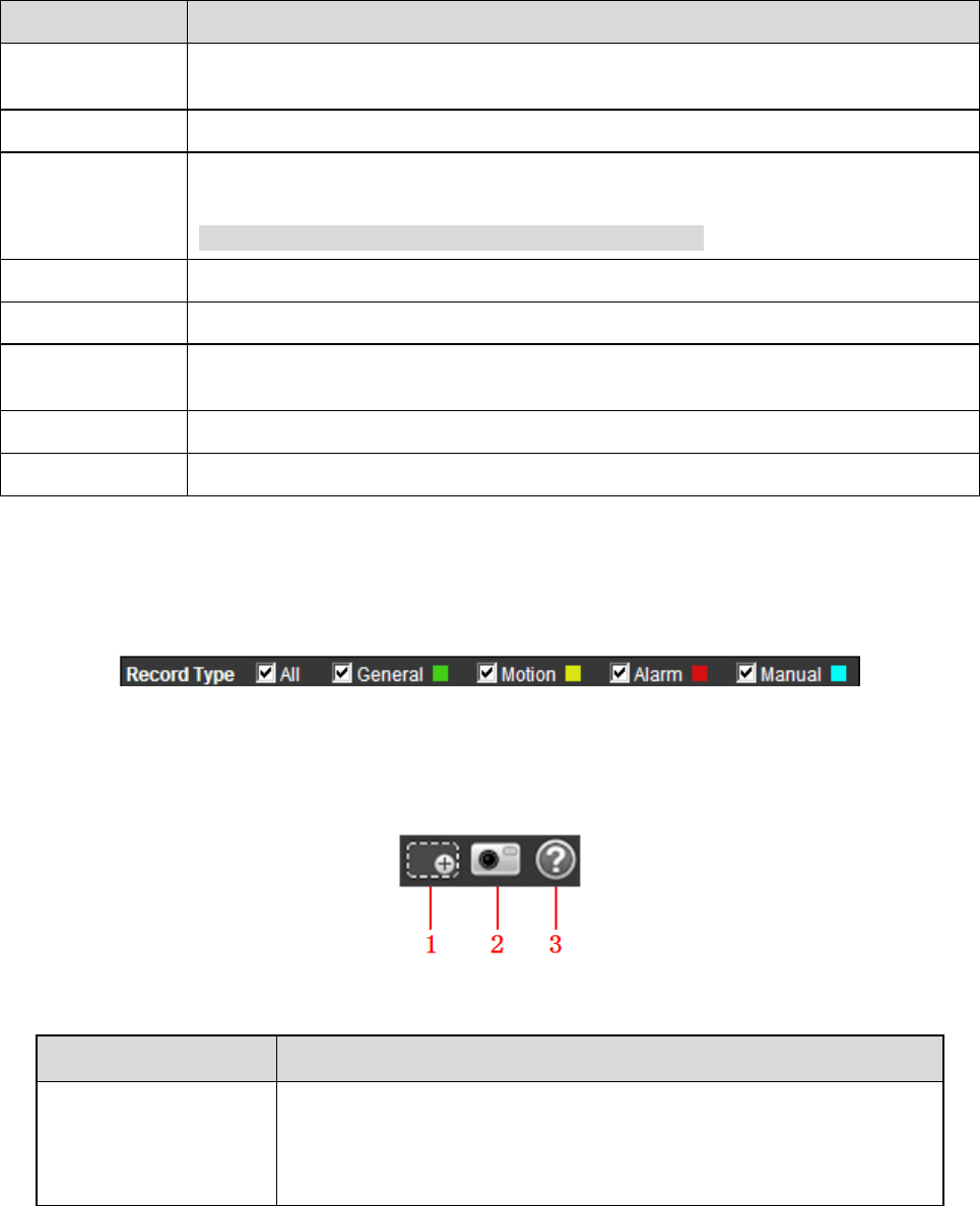
20
Parameter
Function
① Play
When you see this button, it means pausing or not playing record. Click this
button and switch to normal play status.
② Stop
Click this button to stop playing video.
③ Next frame
Click this button to go to next frame.
Note
You shall pause playback when you use this function.
④ Slow
Click this button to play slowly.
⑤ Fast
Click this button to play fast.
⑥ Mute
When this button displays, it means audio is silent. Click this button to switch
back to normal.
⑦ Volume
Left click mouse to adjust volume.
⑧ Rules info
Click the button to display intelligent rules after enabling playback video.
Table 3-2
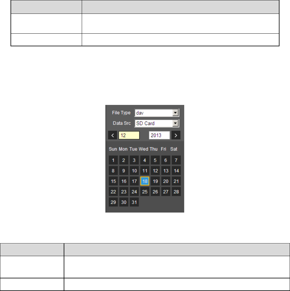
3.1.2 Record Type
Check record file type, the only selected file will be displayed in progress bar and file list. See Figure 3-4.
Figure 3-4
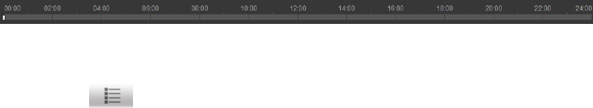
3.1.3 Assistant Function
Video playback assistant function is shown in Figure 3-5.
Figure 3-5
Parameter
Function
1. Digital Zoom
Click it, you can zoom in any area when then playback video is
in original status. In non-original status, you can zoom in
specified zone, Right click mouse to restore its original size.
Click this button; you can scroll to zoom in/out video.
21
Parameter
Function
2. Snapshot
Click this button; you can take snapshot over the video under
playback status. Snapshot will be saved to path in chapter 4.1.2.5
3. Help
Click it to open help file.
Table 3-3
3.1.4 Playback File
In calendar, the date with blue shading means the current date having video record or snapshot file.
See Figure 3-6.
Figure 3-6
Parameter
Function
File Type
Select “dav” and it means record video playback.
Select “jpg” and it means picture playback.
Data Source
It is SD card by default.
Table 3-4
The config steps are shown as follows.
Step 1.
Click the date in blue, time axis displays record file progress bar in color. While, green represents
normal record, yellow represents motion detect record, red represents alarm record, and blue
represents manual record.
Step 2.
22
Click certain time location on the progress bar, playback of the record file starts from this time spot. See
Figure 3-7.
Figure 3-7
Step 3. Click file list , the file of selected date will be displayed in the list.
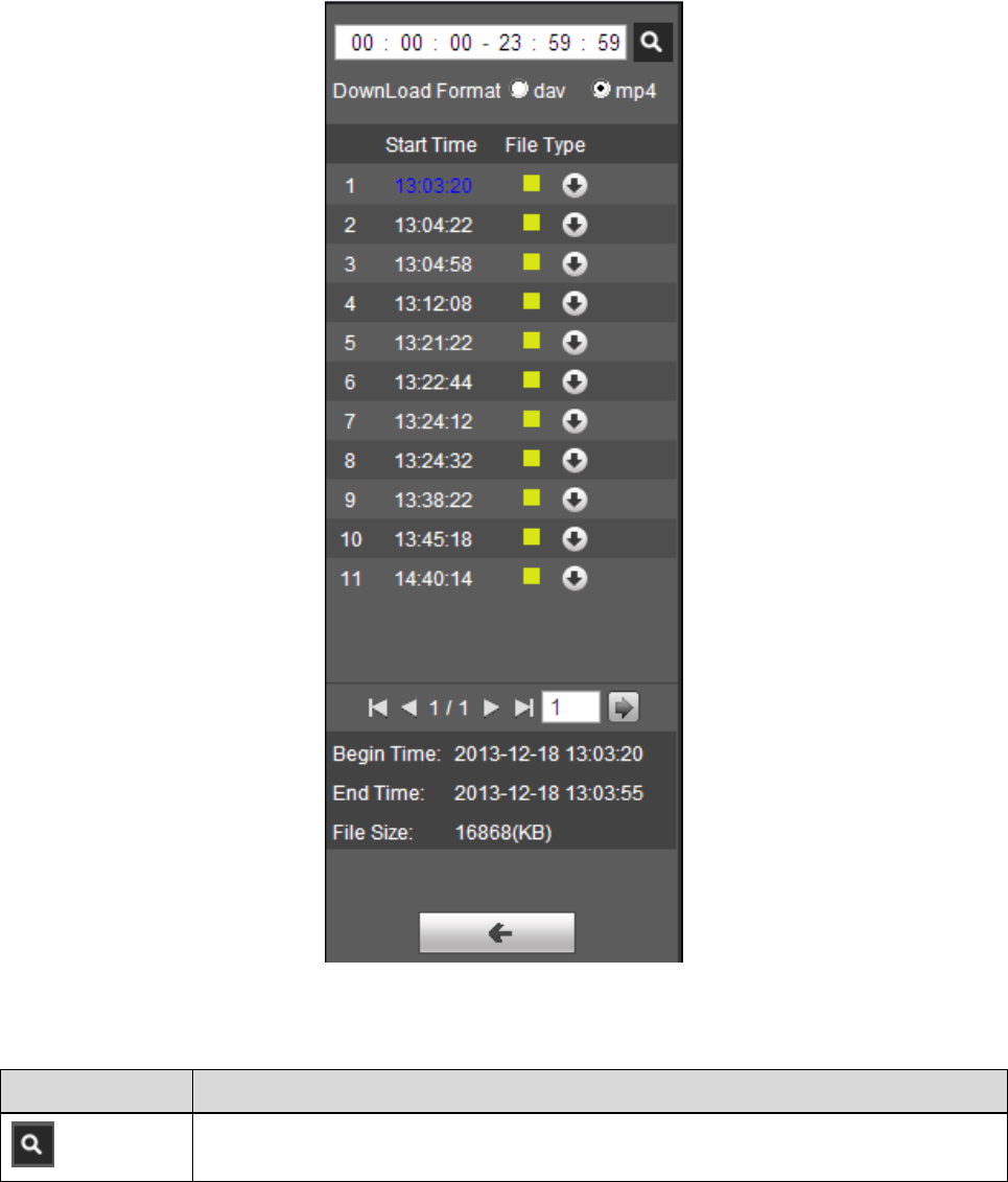
Step 4. Double click the file in list, playback this file and display file size, start time and end time.
See Figure 3-8.
23
Figure 3-8
Parameter
Function
Search
It means searching all the record files between start time and end time of
selected date.
24
Parameter
Function
Record
Download
Format
There are two formats: dav, mp4.
Download
Record type is “dav”, click “Download” button to download file to local.
Record type is “mp4”, click “Download” button and download file to path in
Chapter 3.1.2.5.
Note
System does not support download and playback of MP4 file at the same time.
Back
Click “Back” button to go back to calendar interface, then you can select time
again to operate.
Table 3-5
3.1.5 Playback Clip
Note
The record file which is being playbacked will pause automatically when using playback clip function,
which means that playback clip and playback can’t be implemented at the same time.
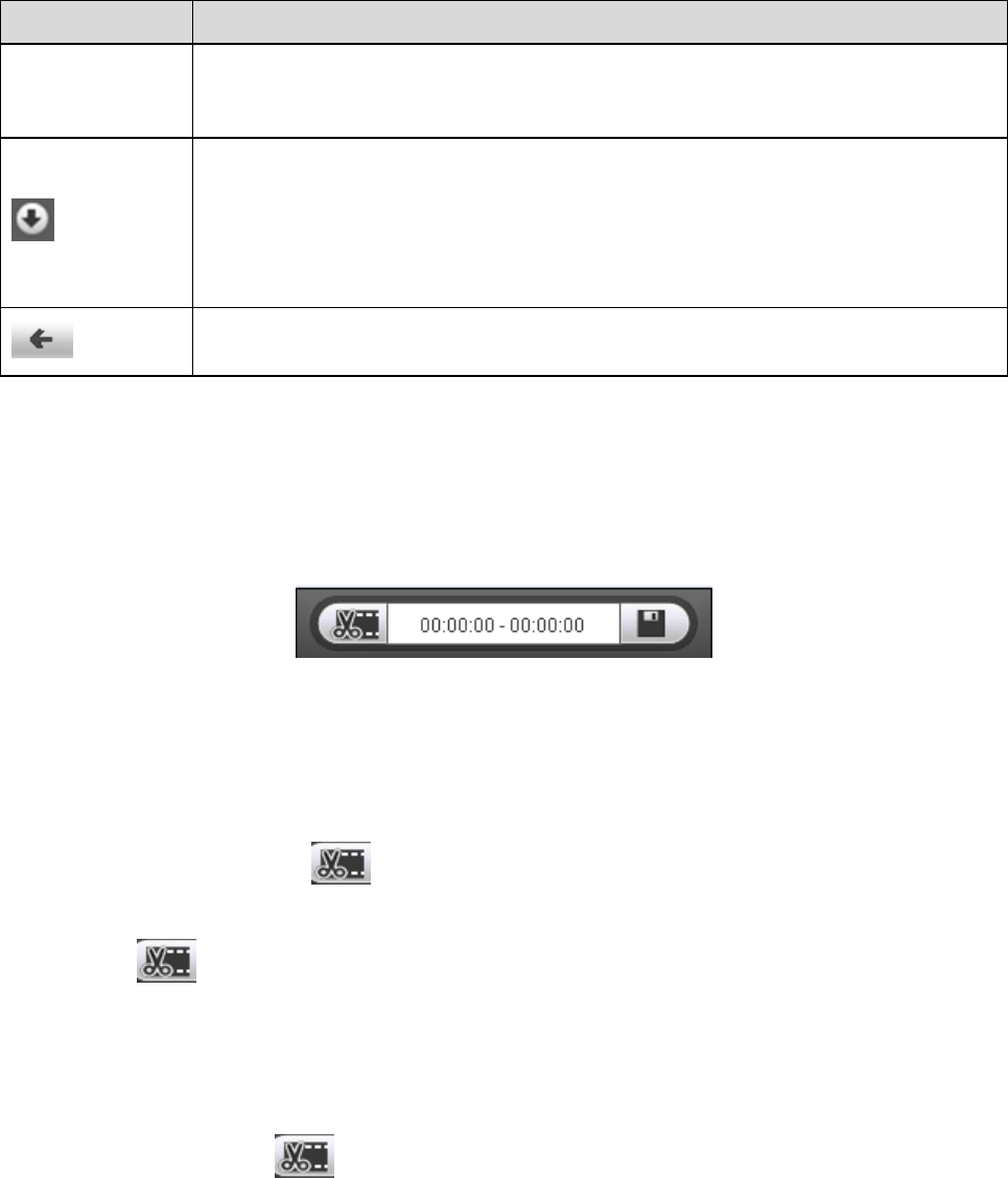
Figure 3-9
Step 1
Click start time to clip on time axis. This time must be within progress bar range.
Step 2
Move mouse above the clip icon , and “Select Start Time” will show up in the lower right corner.
Step 3
Click clip icon and complete the setting of start time for playback clip.
Step 4
Click end time of playback clip on time axis, and the time must be within progress bar range.
Step 5
Move mouse above clip icon , and “Select End Time” will show up in the lower right corner.
Step 6
25
Click clip icon , and complete the setting of end time of playback clip.
Step 7
Click “Save” button to edit file in the path of “Playback Clip” set in the “4.1.2.5 storage path”.
3.1.6 Progress Bar Time Format
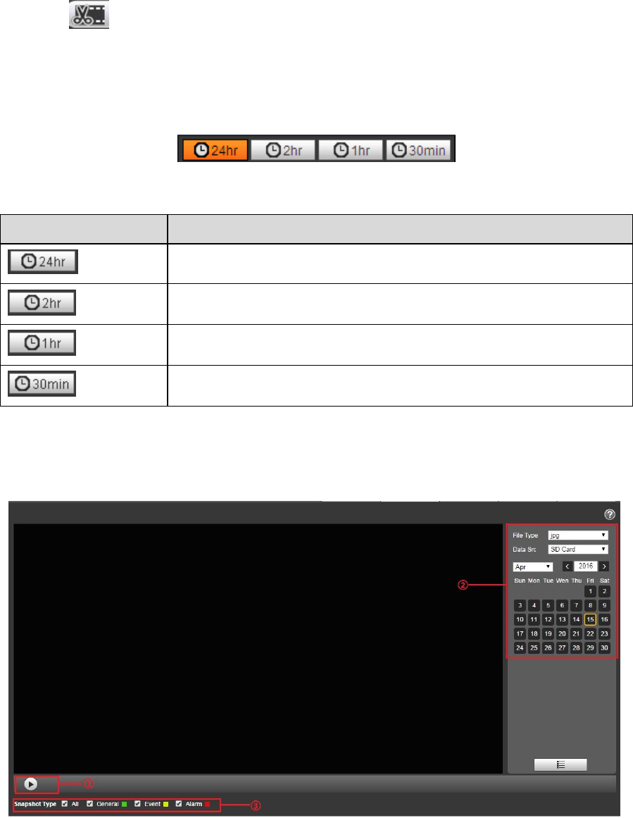
Figure 3-10
Parameter
Function
24 hours
Click it and the progress bar will display in 24-hour mode.
2 hours
Click it and the progress bar will display 2 hours of the video.
1 hour
Click it and the progress bar will display 1 hour of the video.
30 min
Click it and the progress bar will display 30 minutes of the video.
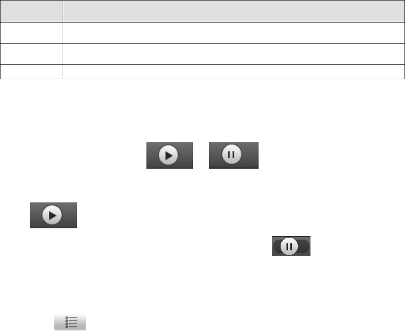
3.2 Picture Playback
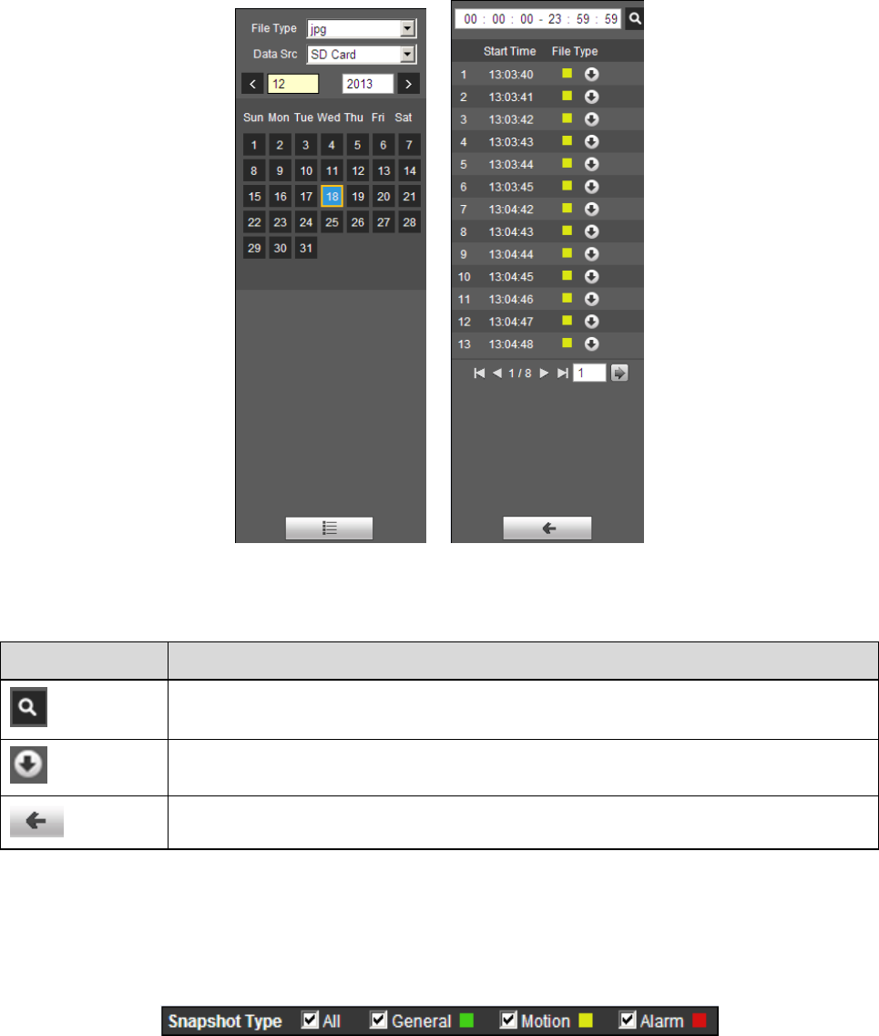
Select file type as “jpg” and the system will display the interface shown in Figure 3-11.
26
Figure 3-11
SN
Note
1
Play function column
2
Playback file column
3
Snapshot type column
Table 3-6
3.2.1 Play Function
The play button is shown as below. See Figure 3-12.
Figure 3-12
Default icon is , and it means pauseing or not playing picture.
Click play button to switch to normal play status. Icon becomes .
Click it to pause and switch it to pause status.
3.2.2 Playback File
Step 1: Click file list , ans the selected snapshot file will be displayed in the list.
Step 2: Double click file in list to playback this snapshot.
27
Figure 3-13 Figure 3-14
Please refer to the following sheet for detailed information.
Parameter
Function
Search
It means all snapshot files within the start time and end time of selected date.
Download
Click download button to download snapshot file to local.
Back
Click back button to return to calendar interface and re-select time to operate.
Table 3-7
3.2.3 Snapshot Type
It will only display the selected type of file in the list after checking the snapshot type. It can also select
the snapshot type to be displayed via the drop-down box above the file list.
Figure 3-15
28
4 Setup
You need to set the camera, video and audio conditions of the network intelligent speed dome in order
to guarantee normal monitoring of the device.
4.1 Camera
4.1.1 Conditions
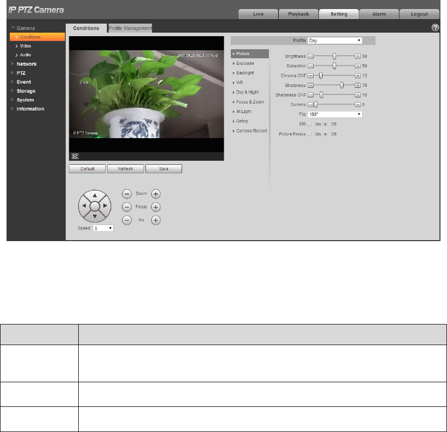
4.1.1.1 Picture
Step 1
Select “Setup > Camera > Conditions > Image”. The system displays the interface of “Image” which is
shown in Figure 4-1.
Figure 4-1
Step 2
Configure parameter info according to the actual needs; see Table 4-1 for more details.
Parameter
Note
Style
It is to set the image display style; you can select soft, standard or vivid. It is
standard by default.
Note: the function is only supported by some models.
Brightness
It is to set the overall brightness of image, the bigger the value is, the
brighter the image becomes. The value ranges from 0 to 100.
Contrast
It is to set the image contrast, the bigger the value is, the bigger the image
bright contrast becomes. The value range is from 0 to 100.

29
Parameter
Note
Saturation
It is to set the image color purity, the higher the purity is, the brighter it
becomes, the lower the purity is, the darker it becomes. The range is from 0
to 100.
Chroma CNT
It is to set the suppression level upon the image color, the bigger the value
is, the more obvious the suppression becomes. The value range is from 0 to
100.
Sharpness
It is to adjust the sharpness level of the image edge. The bigger the value is,
more obvious the edge becomes; it is opposite if the value becomes smaller.
It is easy for the image to generate noise if the value is set too high. The
value range is from 0 to 100.
Sharpness
CNT
It is to adjust the sharpness suppression level of the camera, the bigger the
value is, the stronger the sharpness suppression becomes. The value range
is from 0 to 100.
Gamma
The threshold is mainly used to change image brightness via nonlinear
adjustment mode and improve the dynamic display range of the image. The
bigger the value is, the brighter the image becomes. The value range is
from 0 to 100.
Flip
The function can be used to change the direction of video surveillance
image. It can select normal and flip. It is normal by default.
EIS
It can realize EIS function via image difference value comparison algorithm,
which can effectively solve the problem of image jittering during use and
make HD image even clearer. It is disabled by default.
Picture freeze
After the image is frozen, it directly displays the preset when calling preset.
Table 4-1
Step 3
Click “Save” to make config valid.
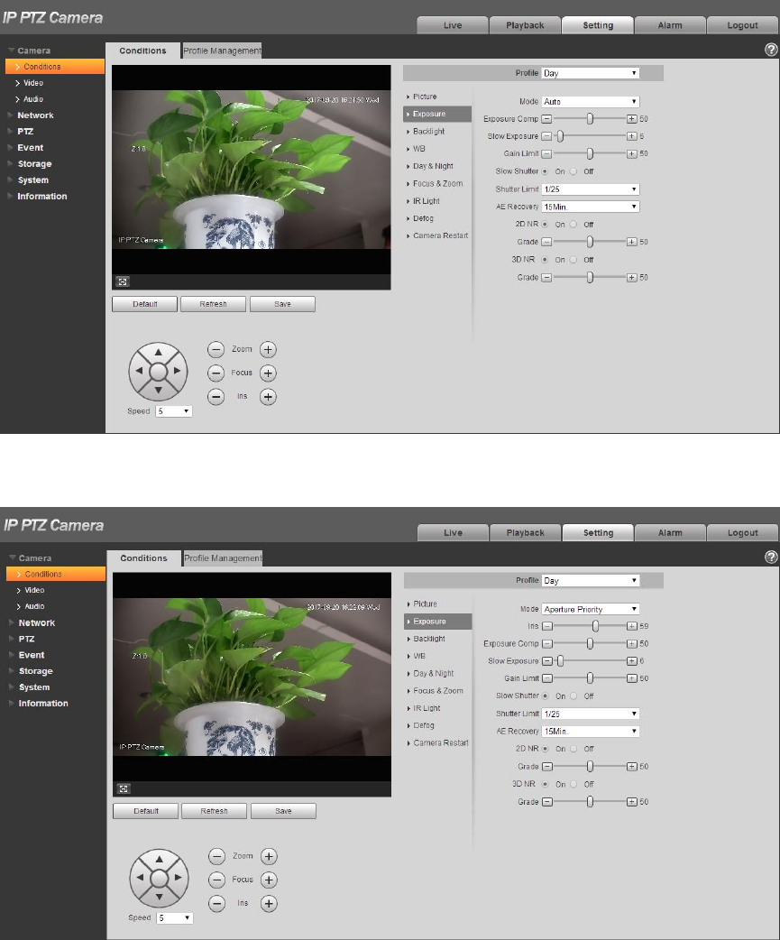
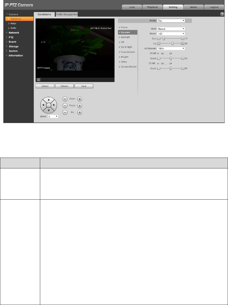
4.1.1.2 Exposure
Step 1
Select “Setup > Camera > Conditions > Exposure”.
The system displays “Exposure” interface, which is shown from Figure 4-2 to Figure 4-6.
30
Figure 4-2
Figure 4-3
31
Figure 4-4
Figure 4-5
32
Figure 4-6
Step 2
Configure parameter info according to actual needs; see Table 4-2 for more details.
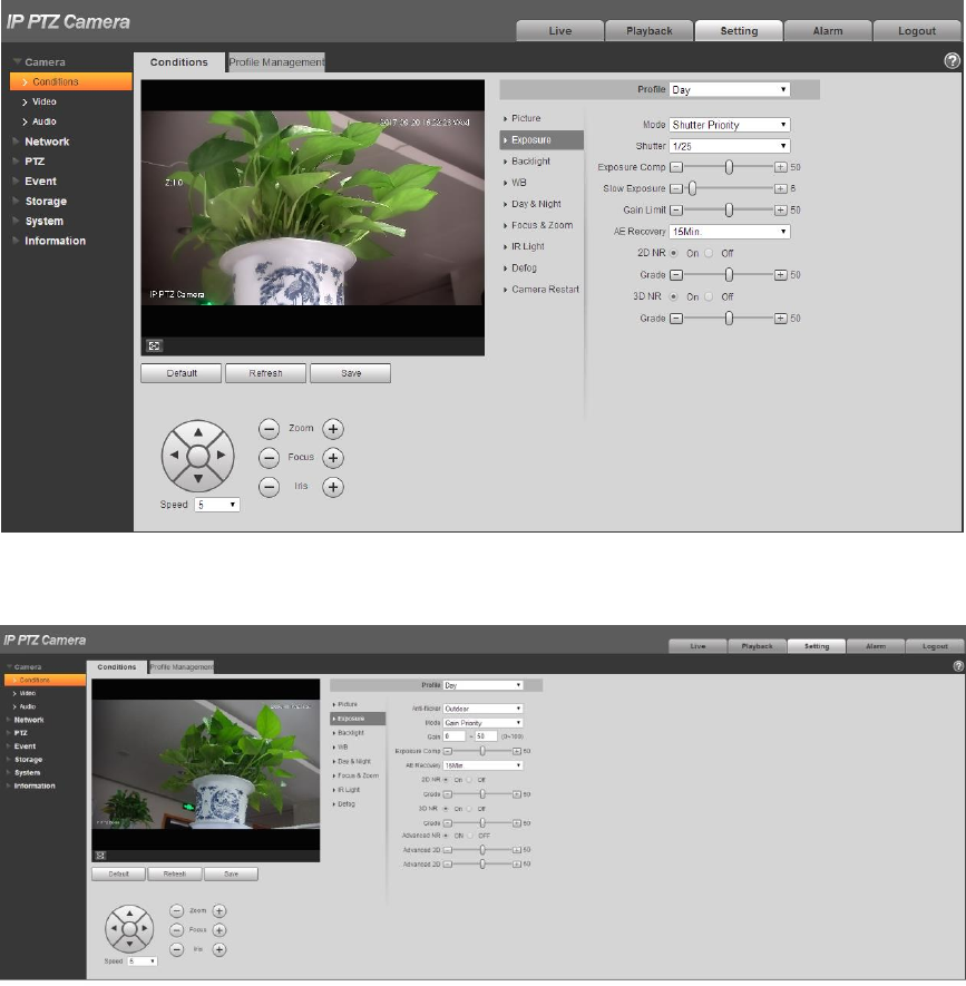
Parameter
Note
Anti-flicker
It can select 50Hz, 60Hz or outdoor.
50Hz: When AC is 50Hz, it can adjust exposure automatically according
to scene brightness, make sure there is no cross stripes in the image.
60Hz: When AC is 60Hz, it can adjust exposure automatically according
to scene brightness, make sure there is no cross stripes in the image.
Mode
It is to set camera exposure mode. It includes: auto/manual/aperture
priority/shutter priority/gain priority. The default is auto mode.
For the auto exposure mode, the image overall brightness will auto
adjust according to different scene brightness in the normal exposure
range.
For manual exposure mode, it can manually adjust gain value and
shutter value; it supports long exposure.
For aperture priority mode, fixed aperture is the set value, it can auto
realize best brightness according to priority drive exposure time to drive
gain mode.
For shutter priority mode, the image overall brightness can auto adjust
according to the adjustment shutter range priority according to different
scene brightness in normal exposure range. If the image brightness is
still improper and gain has reached upper and lower limit of the range,
then it can auto adjust gain value again to make image normal.
For gain priority mode, it can manually adjust gain value and exposure
compensation value.

33
Parameter
Note
Gain Range
It is to set the gain value of exposure; the range is from 0 to 100.
Shutter
It is to adjust shutter time. The bigger the shutter value is, the darker the
image becomes; otherwise it becomes brighter.
Shutter
Range
It is to set the camera exposure time, the range is from 0 to 1000, the unit is
ms.
Iris
It is to set the camera light quantity. The bigger the iris is, the brighter the
image becomes, and otherwise it becomes darker.
Exposure
Comp
It is to set the value of exposure compensation; value range is from 0 to 100.
Slow
Exposure
It is to set the exposure adjustment speed; the value range is from 0 to 100.
Gain limit
It is to set the gain upper limit of exposure, the value range is from 0 to 100.
Slow Shutter
It can capture image via extending auto exposure time in the low illuminance
environment, which can effectively reduce image noise, but it may generate
smear for moving objects.
Shutter limit
It is to restrict the min shutter value of the camera.
Auto
exposure
recovery
After manually adjusting “Iris + or Iris –”, it will recover to the exposure mode
before adjustment regularly.
2D NR
The threshold is used to suppress noise, the higher the level is, the smaller
the noise becomes, and the image appears more blurry then before.
3D NR
The value is used to suppress noise, the higher the level is, the smaller the
noise becomes and the image seems more blurry than before.
Grade
It is to set the NR value range, which is from 0 to 100. The bigger the value
is, the higher the NR level becomes.
Advanced NR
It can realize noise suppression effect via 3D and 2D video filtering method.
Advanced 3D
It is to set 3D grade, the value range is from 0 to 100.
Advanced 2D
It is to set 2D grade, the value range is from 0 to 100.
Table 4-2
Step 3
Click “OK” to complete config.
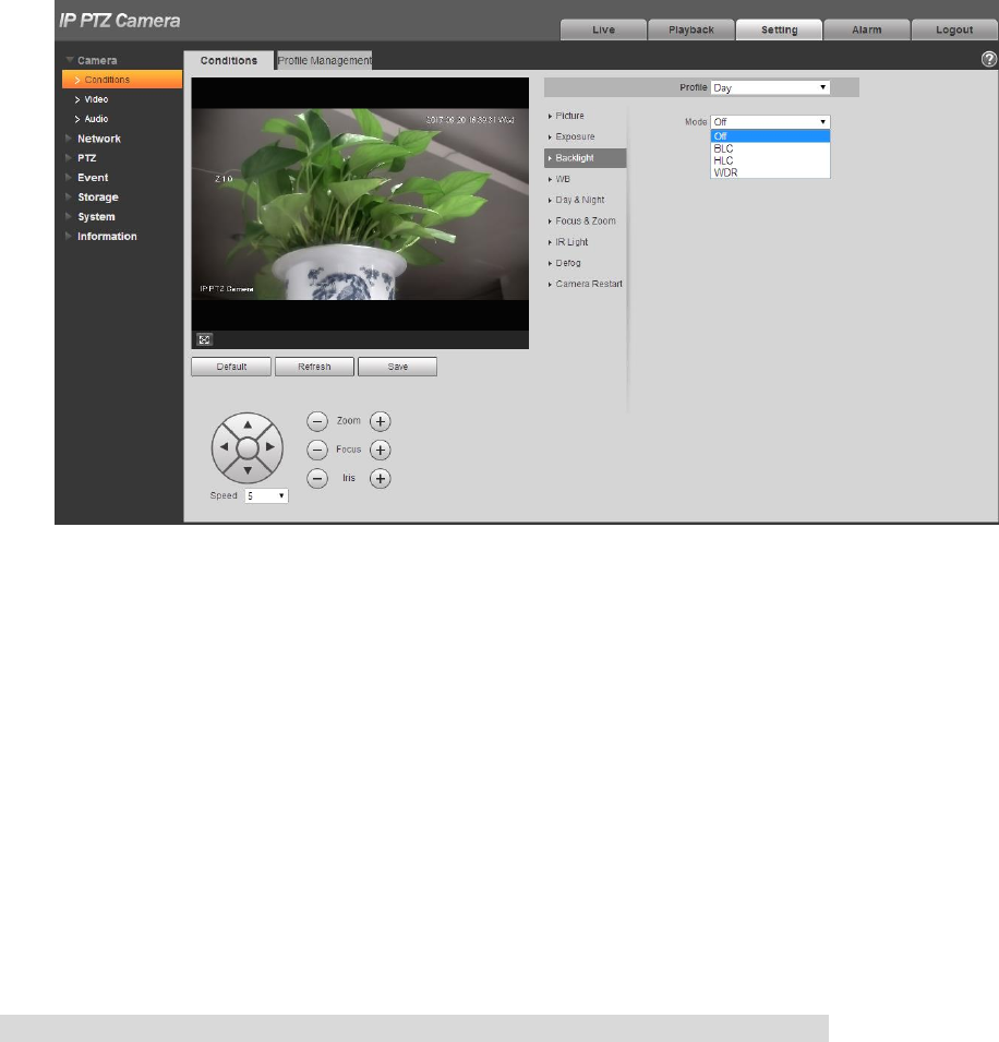
4.1.1.3 Backlight
Note
It fails to set backlight function when “Defog” is enabled, there will be prompt on the WEB interface.
The function is used to adjust the backlight compensation mode of the monitoring image. The config
steps are shown as follows:
Step 1
Select “Setup > Camera > Condition > Backlight” and the system will display the interface of “Backlight”,
which is shown in Figure 4-7.
Step 2
Set the mode according to the interface.
34
Figure 4-7
Step 3
Select backlight mode which includes BLC, WDR and HLC.
Backlight compensation: backlight compensation can make the dark part of the main shooting
object clear in the backlighting environment.
WDR: Enable WDR to suppress the over bright area and compensate over dark area, which can
make the whole image a quite clear status.
HLC: HLC is used to weaken the highlight area, which can be applied in the areas such as toll gate,
entrance and exit of parking lot, etc. As for extreme light, it can take snapshot upon human face in
dark environment and realize quite good effect of license plate details.
Step 4
Click “Save” to complete config.
Note
Other backlight mode config will not be valid when the “Mode” is selected as “Off”.
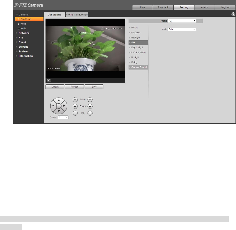
4.1.1.4 White Balance
White balance is used to restore white objects, after setting white balance mode; it can make the white
object display white status in different environments.
Step 1
Select “Setup > Camera > Conditions > WB”.
The system displays the interface of “WB”, which is shown in Figure 4-8.
35
Figure 4-8
Step 2
Select “WB” mode.
As for WB mode, it can select auto, indoor, outdoor, ATW, manual, sodium lamp, natural and street
lamp. It is “Auto” by default.
Step 3
Click “Save” to complete config.
4.1.1.5 Day & Night
Note
It fails to set defog function after enabling “Day/Night” function, there will be prompt on the WEB
interface.
The function can be used to set the conversion between color mode and B/W mode, which can
effectively guarantee that it can still monitor clear image even in dark environment for the intelligent
speed dome. The config steps are shown as follows.
Step 1
Select “Setup > Camera > Conditions > Day & Night”.
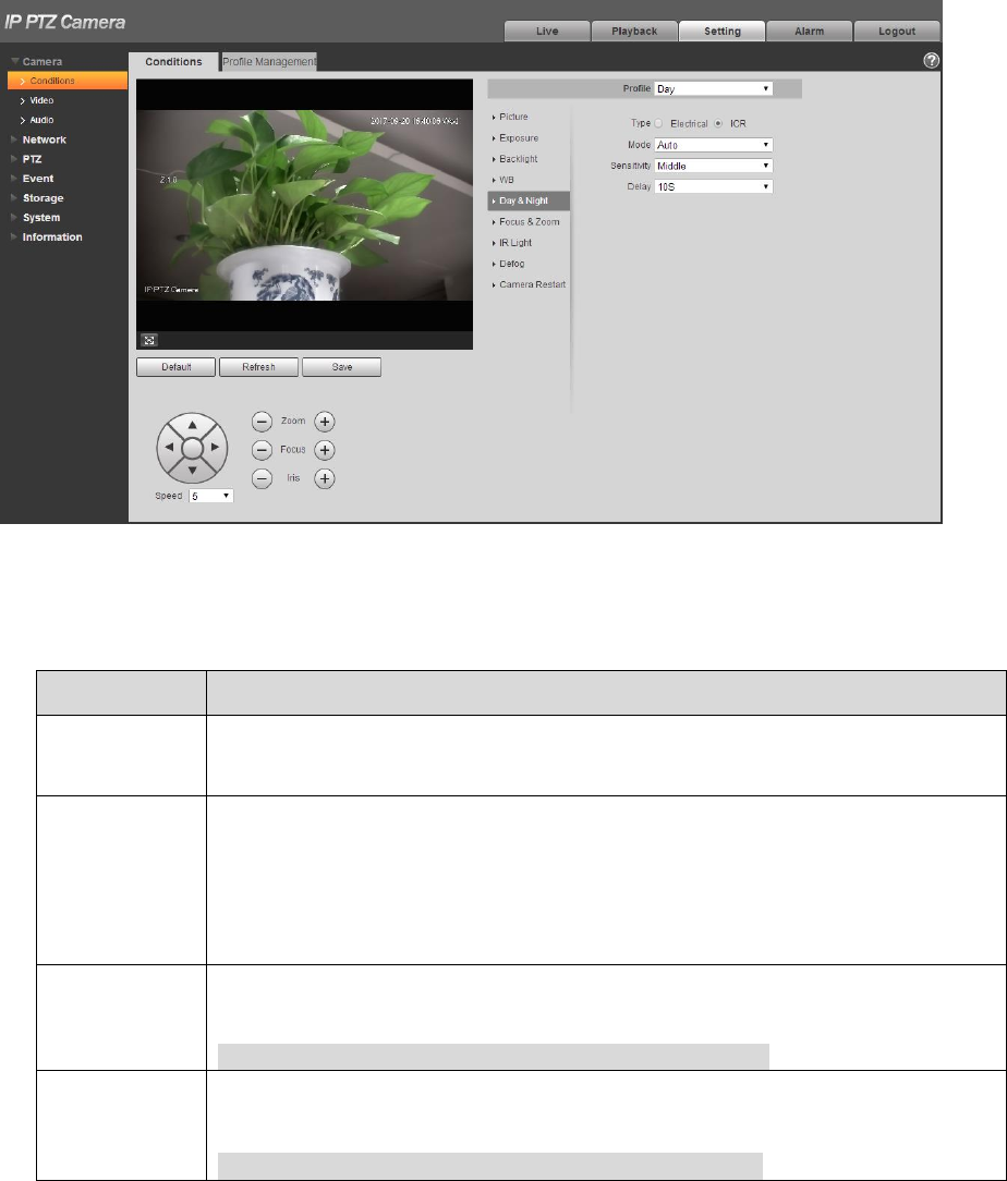
36
The system displays the interface of “Day & Night” mode, which is shown in Figure 4-9.
Figure 4-9
Step 2
Configure parameter info according to the actual needs; refer to Table 4-3 for more details.
Parameter
Note
Type
Day/night switch mode can select electrical and ICR, it is ICR by default.
ICR: Mechanical day/night switch uses filter for day & night switch.
Electrical: It uses image processing mode for day & night switch.
Mode
It is to set image color and b/w mode, which is not influenced by the
selection of config profile. It is auto mode by default.
Color:The camera will only output color image.
Auto:It can select to output color or black & white image according to
the environment adaptation.
Black & White:The camera will only output black & white image.
Sensitivity
It is used to adjust the sensitivity of switch between color and black & white.
It can select high, middle and low, it is middle by default.
Note
It can set sensitivity only when day/night mode is auto.
Delay
It is used to adjust the delay value of switch between color and black &
white. The value range is 2s~10s.
Note
It can set delay only when the day/night mode is auto.
Table 4-3
Step 3
37
Click “Save” to complete config.
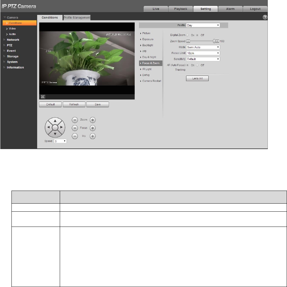
4.1.1.6 Zoom & Focus
Digital zoom means zooming in part of the image, the bigger it zooms in, the more blurry it becomes.
Step 1
Select “Setup > Camera > Conditions > Focus & Zoom”.
The system displays the interface of “Focus & Zoom”, which is shown in Figure 4-10.
Figure 4-10
Step 2
Configure parameter info according to the actual needs; please refer to Table 4-4.
Parameter
Note
Digital zoom
It is used to set if it is to enable digital zoom function, it is off by default.
Zoom speed
It is to set camera zoom speed, the bigger the value is, the faster the zoom
speed becomes.
Mode
It is to control the trigger mode of focus, you can select semi-auto, manual
and auto.
Semi auto: it will actively trigger focus when detecting zoom, ICR switch
and etc.
Auto: It will actively trigger focus when detecting scene change and
zoom, ICR switch and etc.
Manual: The users can adjust focus location by themselves; the device
won’t trigger focus actively.

38
Parameter
Note
Focus limit
It is to set the nearest distance of focus, and focus on the object beyond the
distance, the auto option will make it select proper nearest distance
automatically according to the different zoom value.
Sensitivity
It is to set the steady ability or anti-interference capability of focus, the lower
the value is, the steadier it becomes, the higher the value is, the stronger the
anti-interference capability becomes.
AF tracking
The image becomes relatively clear during zoom if the function is enabled. If
the function is disabled, then the zoom speed becomes relatively fast during
zoom.
Lens
initialization
Click the button and it will implement lens initialization automatically, at this
moment, it will realize correction of zoom and focus for the camera.
Table 4-4
Step 3
Click “Save” to complete config.
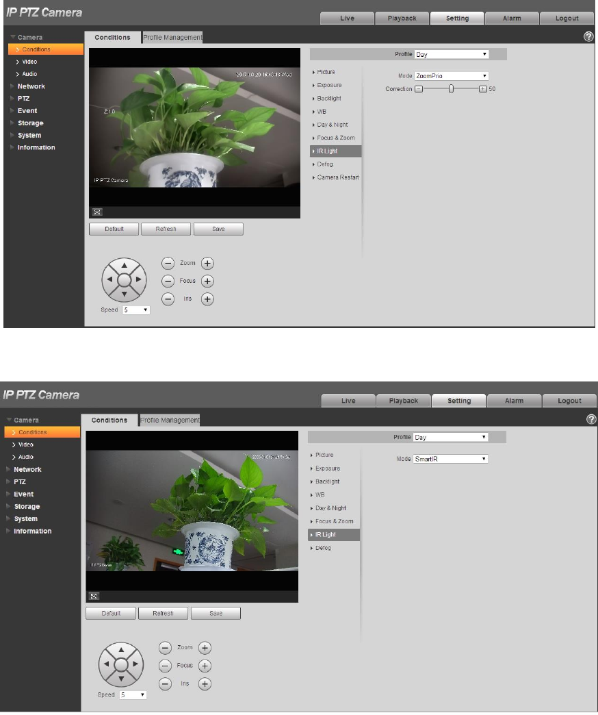
4.1.1.7 IR Light
Currently, common compensation lights include IR light, white light and laser light, different models
support different types of compensation lights with different config interfaces. Please refer to actual
config interface for more details. It is to introduce the config modes of several compensation lights in
this chapter.
IR light/White light
Different types of compensation lights use the following conditions:
When Day/Night mode is switched to “B/W”, the monitoring image becomes black and white, and at
this moment the IR light is enabled.
When Day/Night mode is switched to “Color”, the monitoring image becomes color, and at this
moment the white light is enabled.
When Day/Night mode is switched to “Auto”, the color of monitoring image is switched according to
the environmental brightness, the compensation light changes according to the monitoring image;
The IR light is enabled in B/W mode, white light is enabled in color mode.
Note
Some models are equipped with photoresistance. IR/white light will be enabled automatically when
the environmental brightness is too low.
It is to take IR light as an example to introduce the parameters and functions of config interface.
The config steps of IR light/white light are shown as follows:
Step 1
Select “Setup > Camera > Conditions > IR Light”.
The system displays the interface of “IR Light”, which is shown in Figure 4-11.
39
Figure 4-11
Figure 4-12
40
Figure 4-13
Step 2
Configure parameter info according to the actual needs, please refer to Table 4-5 for more details.
Parameter
Note
Mode
It is used to set the mode of IR light, you can select zoom priority, SmartIR,
manual and off
Zoom priority: It can auto adjust the brightness of IR light according to
the actual zoom rate.
SmartIR: The device can control IR light brightness according to the
actual zoom rate and overexposure.
Manual: It is to set the brightness value of IR light manually.
Off: It is to disable compensation light.
Note
Only IR light supports SmartIR mode.
Light
compensation
It is used to compensate the brightness of IR light; the value range is from 0
to 100.
Near light
It is used to set the brightness of near light; the value range is from 0 to 100.
Far light
It is used to set the brightness value of far light; the range is from 0 to 100.
Table 4-5
Step 3
Click “Save” to complete setting.
41
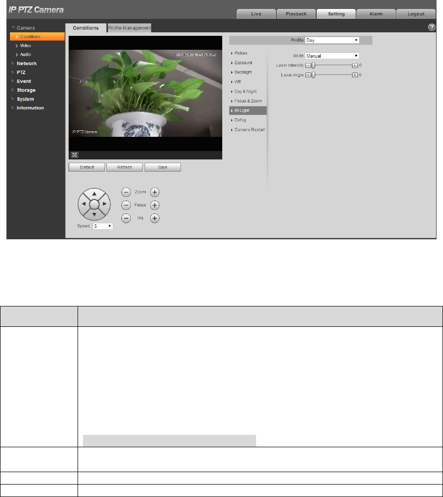
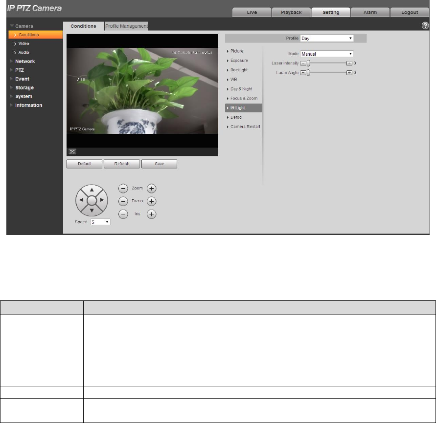
Laser Light
Laser light makes compensation for the ambient environment when it is used for long-distance
monitoring.
The config steps of laser light are shown as follows:
Step 1
Select “Setup > Camera > Conditions > IR Light” and the system will display the interface of “IR Light”,
which is shown in Figure 4-14.
Figure 4-14
Step 2
Configure parameter info according to actual needs; please refer to Table 4-6 for more details.
Parameter
Note
Mode
It is used to set the mode of laser light, it can select Zoomprio or manual, it
is “Zoomprio” by default.
Zoomprio: The camera can auto adjust laser light brightness according
to the zoom rate of light.
Manual: It is manually to set laser light brightness and angle value
scattered by light beam.
Laser Intensity
It is to set the intensity of laser light, the value range is from 0 to 100.
Laser Angle
It is to set the angle scattered by light beam, the value range is from 0 to
100.
Table 4-6
Step 3
Click “Save” to complete config.
42
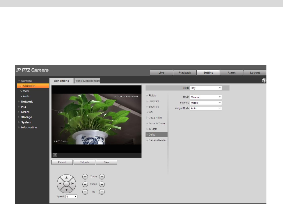
4.1.1.8 Defog
Note
It fails to set defog function after enabling “Backlight” function, there will be prompt on the WEB interface.
The image quality may become weak if the camera is in the environment with fog or haze, the image
can realize auto correction in the auto mode; it can also select different intensity manually according to
the fog concentration, which is to adjust the image definition.
Step 1
Select “Setup > Camera > Conditions > Defog”.
The system displays the interface of “Defog”, which is shown in Figure 4-15 or Figure 4-16.
Figure 4-15
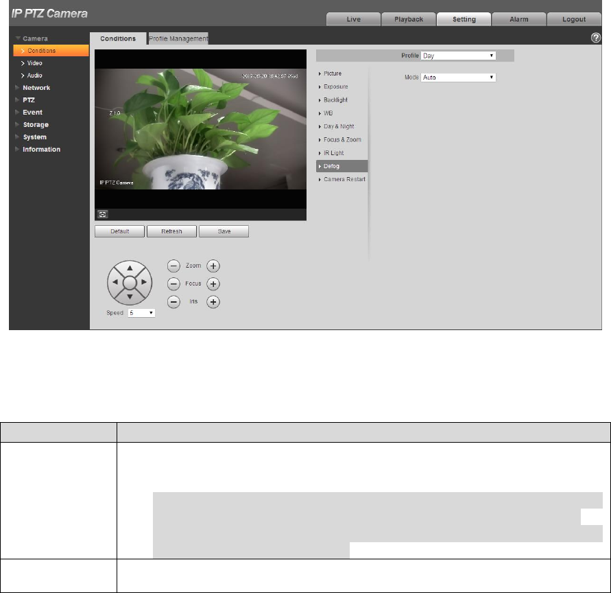
43
Figure 4-16
Step 2
It is to configure parameter info according to actual needs, please refer to Table 4-7 for more details.
Parameter
Note
Mode
It is used to set the defog mode, it can select auto, manual and off. It is
“Off” by default.
Note
For the devices which support optical defog. Optical defog and
electronic defog realize self-adaptive switch according to algorithm.
For the devices which support optical defog. Electronic defog is
enabled by default in off mode.
Intensity
It is used to set the defog intensity; you can select low, middle or high. It is
“high” by default.
Table 4-7
Step 3
Click “Save” to complete config.
4.1.1.9 Profile Management
It can select three modes of profile management, such as normal, full time and schedule.
When it selects “Normal”, the video will be monitored according to the normal config of the camera.
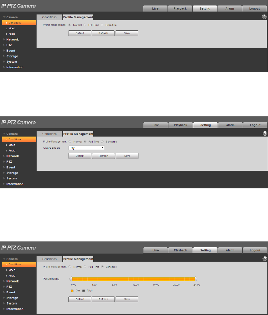
44
Figure 4-17
When it selects “Full time”, it can select day or night, which is corresponding to the config file of the
camera conditions for day or night.
Figure 4-18
When it selects “Schedule”, you can select one period as day config, the other period as night
config. If the config profile management is displayed according to schedule, you can set 0:00~
12:00 as day config, and 12:00~24:00 as night config.
Figure 4-19
45
4.1.2 Video
It is to set video, snapshot, overlay, ROI and path.
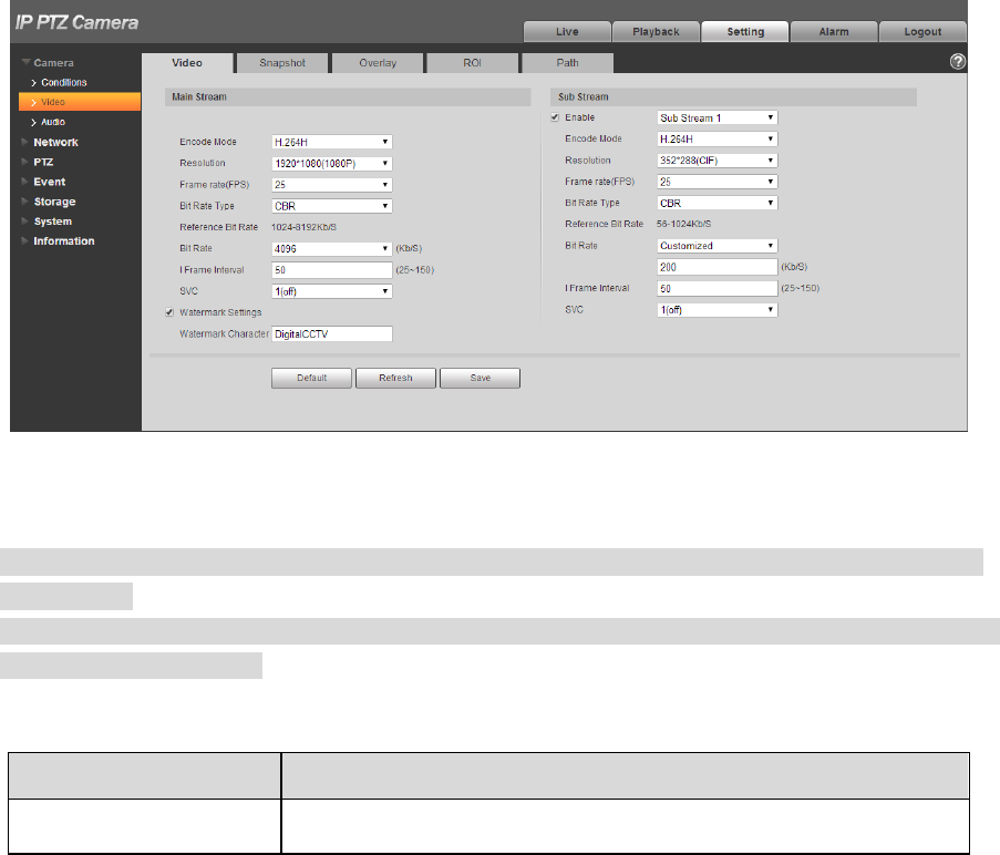
4.1.2.1 Video
It is to set video stream of the monitoring image. The config steps are shown as follows;
Step 1
Select “Setup > Camera > Video > Video”.
The system displays the interface of “Video stream”, which is shown in Figure 4-20.
Figure 4-20
Note
Different device video may have different config interface, please refer to the actual interface for
more details.
Different video streams may be corresponding to different default value, please refer to the actual
interface for more details.
Step 2
Configure parameter info according to the actual needs, please refer to Table 4-8 for more details.
Parameter
Function
Sub Stream Enable
Please check the box here to enable extra stream function. This
function is enabled by default.

46
Parameter
Function
Encode mode
There are seven options: H.264, H.264H, H.264B, H.265,
MJPEG and MPEG4.
H.264: Main Profile encode mode.
H.264H: High Profile encode mode.
H.264B: Baseline Profile encode mode.
H.265: Main Profile encode mode.
MJPEG: In this encode mode, the video needs to enlarge
bit stream to guarantee the video definition. You can use
the max bit stream value in the recommended bit to get the
better video output effect.
Smart Codec
It can set smart codes as on or off.
Resolution
There are multiple resolution types. You can select from the
dropdown list.
For each resolution, the recommended bit stream value is
different.
Frame Rate (FPS)
PAL: 1~25f/s,NTSC: 1~50f/s..
The frame rate may vary due to different resolutions.
Bit Rate Type
There are two options: VBR and CBR.
Please note, you can set video quality in VBR mode.
In MJPEG encode mode, only CBR is available.
Reference Bit Rate
Recommend a reasonable bit rate value range according to the
resolution and frame rate you have set.
Bit Rate
In VBR, the bit rate here is the max value.
In CBR, the value is fixed.
Refer to “Reference Bit Rate”, bit rate value can provide
best reference range.
I Frame interval
Here you can set the P frame amount between two I frames, the
range varies according to the frame rate, the max is 150, it is
recommended to set twice as big as the frame rate.
SVC
Frame rate can realize layered coding, it is a scalable encoding
mode in time domain, and it is 1 by default, which is not layered.
It can set 2, 3, 4 layer coding setting.
Watermark Settings
By calibrating watermark, to see if video is modified. Select
Watermark function. Default watermark is Digital CCTV.
Watermark character can only be number, letter, _, - within 128
characters.
Table 4-8
Step 3
Click “Save” to complete config.
47
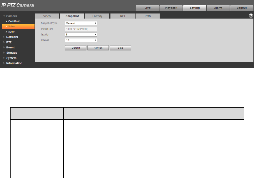
4.1.2.2 Snapshot
It is to set the stream info of snapshot. The config steps are shown as follows:
Step 1
Select “Setup > Camera > Video > Snapshot” and the system will display the interface of “Snapshot”,
which is shown in Figure 4-21.
Figure 4-21
Step 2
Configure parameter info according to the actual needs; please refer to Table 4-9 for more details.
Parameter
Function
Snapshot type
It includes General and Event.
Image size
It is the same with the resolution of snapshot (main stream or
sub stream).
Quality
It is to set the image quality. There are six levels from 1 to 6.
Interval
It is to set snapshot frequency. The value ranges from 1s to 7s
or customized.
Table 4-9
Step 3
Click “Save” to make config valid.
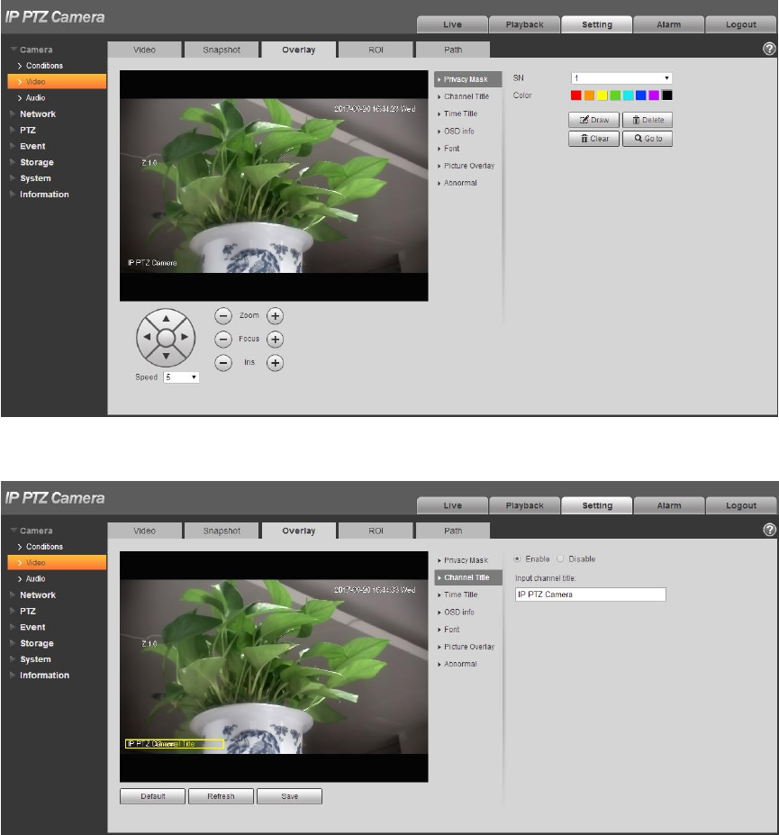
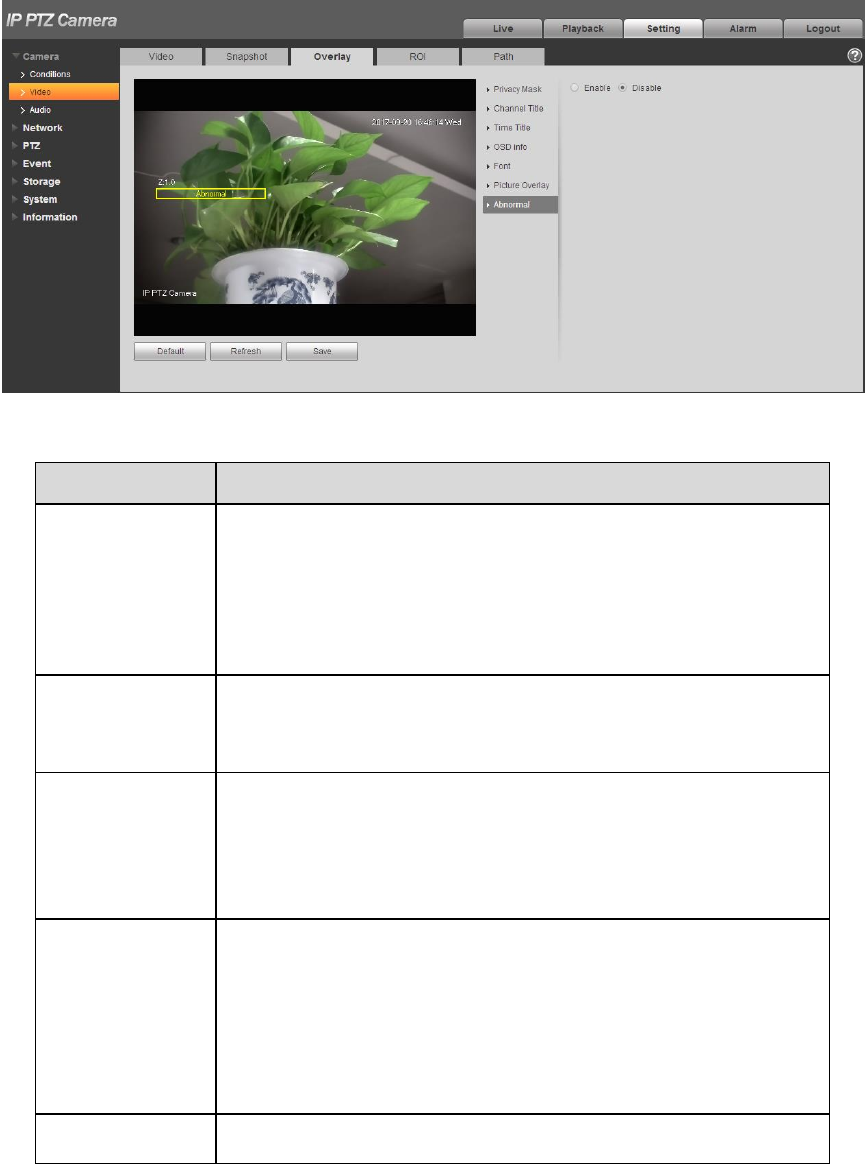
4.1.2.3 Video Overlay
It is to set the info which is to be overlaid on the monitoring image. The config steps are shown as
follows:
Step 1
Select “Setup > Camera > Video > overlay” and the system will display the interface of “Overlay”.
Step 2
It is to configure video overlay info according to actual needs. The config interface is shown from Figure
4-22 to Figure 4-28. Refer to Table 4-10 for more details.
48
Figure 4-22
Figure 4-23
49
Figure 4-24
Figure 4-25
50
Figure 4-26
Figure 4-27
51
Figure 4-28
Parameter
Function
Privacy mask
Click “Draw” to draw privacy mask in the image preview
area.
Click “Delete” to delete corresponding privacy mask.
Click “Clear” to clear all the privacy mask areas.
Set “Privacy Mask SN”, click “Go to” to check the
corresponding privacy mask area of the “Privacy Mask
SN”.
Channel Title
Check “Enable” to display channel title in the video
monitoring window; check “Disable” not to display.
You can use the mouse to drag the channel tile to adjust
the position of channel title.
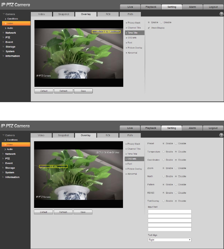
Time Title
Check “Enable” to display time title in the video monitoring
window; check “Disable” not to display.
You can drag “Time Title” box to adjust the position of time
title.
Check “Display Week” to display week info on the time
title.
OSD
Check the corresponding “Enable” button, and it will
display preset, temperature, PTZ coordinates, zoom, north
and text overlay in the video monitoring window; check
corresponding “Disable “button and it won’t display.
Click “Set North” to set the current location as north.
You can adjust preset, temperature, PTZ coordinates,
zoom, north and text overlay via dragging “OSD Info” box.
Alignment include align left and align right.
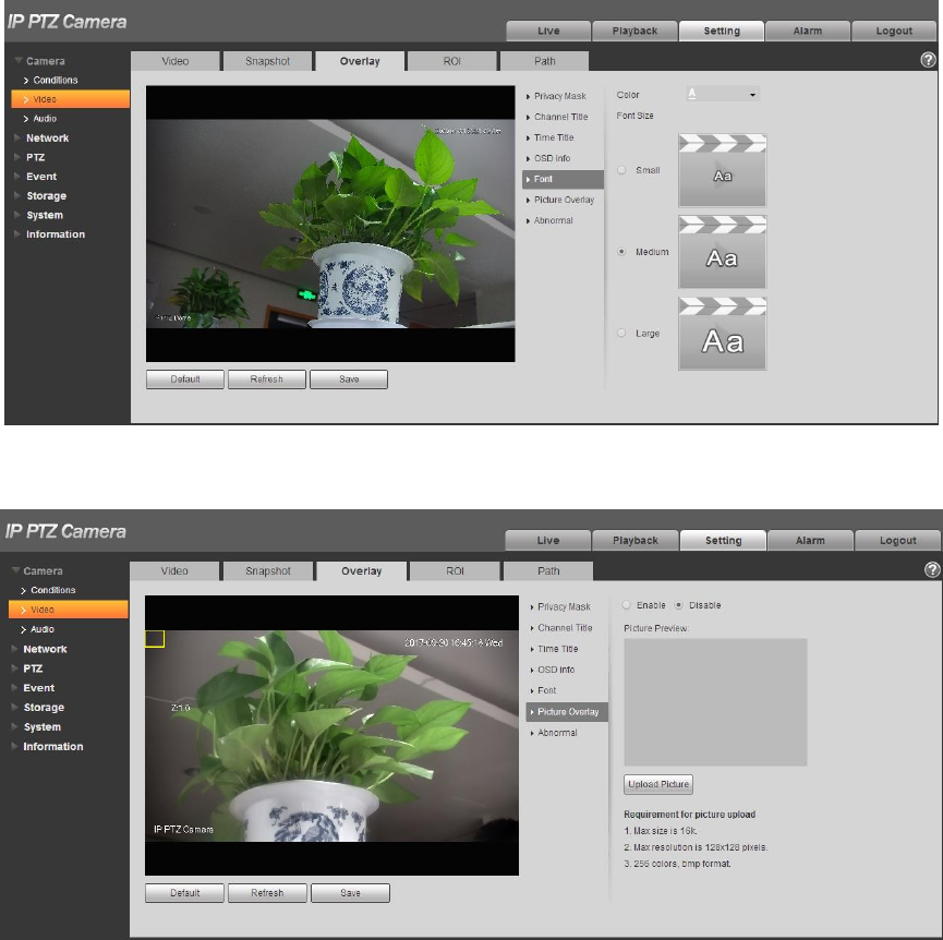
Font
It is set the font of channel title, time title, OSD info, it can
set color, size and row height.
52
Picture Overlay
You can enable this function to display overlay picture.
Click disable to turn it off.
Click Upload Picture to overlay local picture into monitoring
window. You can drag the yellow box to move it.
Note
You cannot enable OSD info and picture overlay at the same
time.
Abnormal
It is to set if it will display abnormity in the monitoring picture.
Table 4-10
Step 3
Click “Save” to complete config.
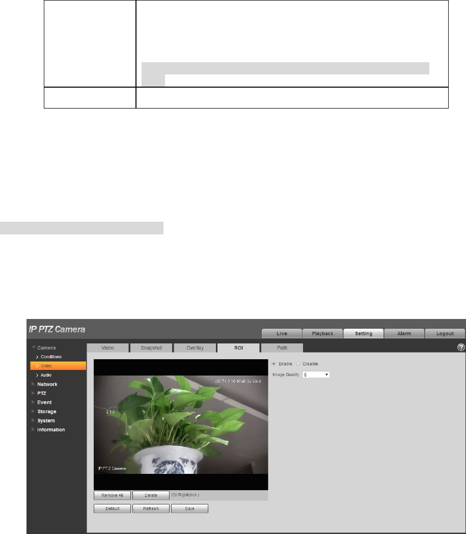
4.1.2.4 ROI
Note
Some devices do not support ROI.
You can set the key monitoring area as the ROI and set image quality upon the area. The config steps
are shown as follows.
Step 1
Select “Setup > Camera > Video > ROI”.
The system will display the interface of “ROI”, which is shown in Figure 4-29.
Figure 4-29
Step 2
Select “Enable “to enable ROI function.
Step 3
53
Press the left mouse button and draw area on the monitoring image. It can set max 4 areas.
Click “Delete” or press right mouse button to delete corresponding area.
Click “Remove all” to remove all the areas.
Step 4
Set the image quality of the corresponding ROI.
Step 5
Click “Save” to make config valid.
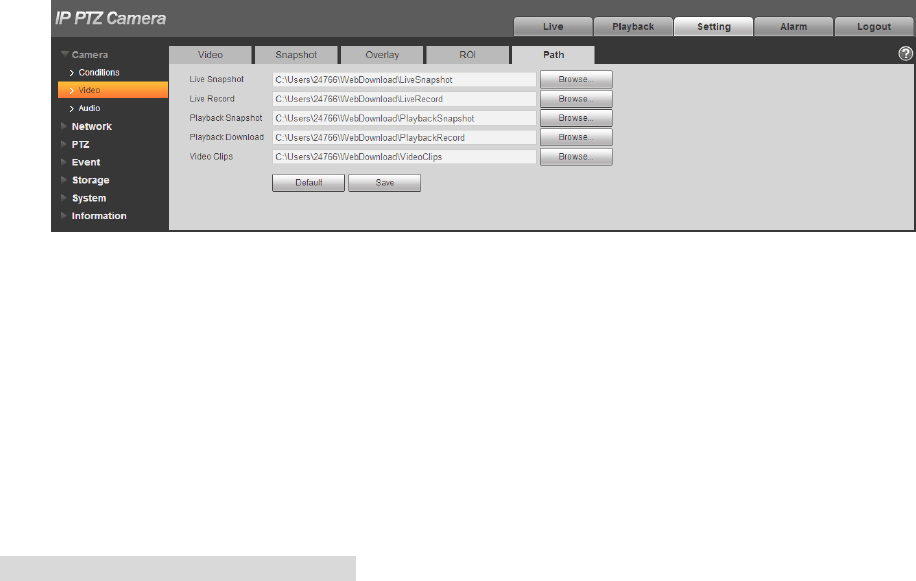
4.1.2.5 Path
The storage path is activated with snapshot and record in the live interface, which can set the storage
path of monitoring snapshot and monitoring record respectively.
The storage path is activated with snapshot, download and clip in the playback interface, which can set
the storage path of playback snapshot, record download and playback clip respectively.
Step 1
Select “Setup > Camera > Video > Path”.
The system will display the interface of “Storage Path”, which is shown in Figure 4-30.
Figure 4-30
Step 2
Set the corresponding storage path.
The default live snapshot path: C:\Users\admin\WEBDownload\LiveSnapshot.
The default live record path:C:\Users\admin\WEBDownload\LiveRecord.
The default playback snapshot path: C:\Users\admin\WEBDownload\PlaybackSnapshot.
The default playback download path: C:\Users\admin\WEBDownload\PlaybackRecord.
The default playback clip path: C:\Users\admin\WEBDownload\VideoClips.
Note
Admin is locally logged in PC account.
Step 3
Please click the “Save” button to make config valid.
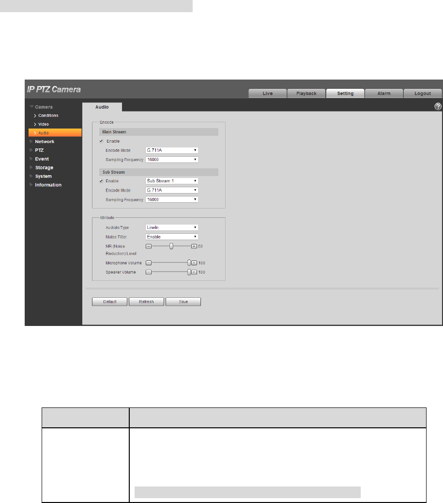
4.1.3 Audio
54
Note
Some models don’t support audio function.
It is to set the audio parameters of the device. The config steps are shown as follows:
Step 1
Select “Setup > Camera > Audio”.
The system will display the interface of “Audio”, which is shown in Figure 4-31.
Figure 4-31
Step 2
Please configure info of each parameter according to the actual needs, refer to Table 4-11 for more
details.
Parameter
Function
Audio enable
Select the audio channel number which needs to be enabled:
the stream is A/V composite stream; otherwise it only contains
video only.
Note
Audio can be enabled only when video is enabled.
55
Encode mode
The encode mode includes G.711A, G.711Mu, G.726 and
AAC.
The default is G.711A.
Note
The audio encode mode which is set here can make both audio
stream and bidirectional talk valid at the same time.
Sampling
frequency
It includes 8k, 16k, 32k, 48k and 64k. It is 16K by default.
Audio in type
It is to set audio input type, it is LineIn by default.
Noise filter
It is to set if it is to enable noise filter function, it is enabled by
default.
Microphone
volume
It is to adjust the volume of the microphone; the value range is
from 0 to 100.
Note
The function is only supported by some models.
Speaker volume
It is to adjust the volume of the speaker; the value range is from
0 to 100.
Note
The function is only supported by some models.
Table 4-11
Step 3
Click “Save” to complete config.
4.2 Network
4.2.1 TCP/IP
4.2.1.1 TCP/IP
You need to configure the IP address and DNS server of the intelligent speed dome, make sure it can
be mutually connected to other devices in the networking.
Note
Please confirm the intelligent speed dome has connected to network correctly before setting network
parameters.
Please distribute IP address of the same network segment if there is no router in the network.
It needs to set corresponding gateway and subnet mask if there is no router in the network.
Step 1
Select “Setup > Network > TCP/IP”.
56
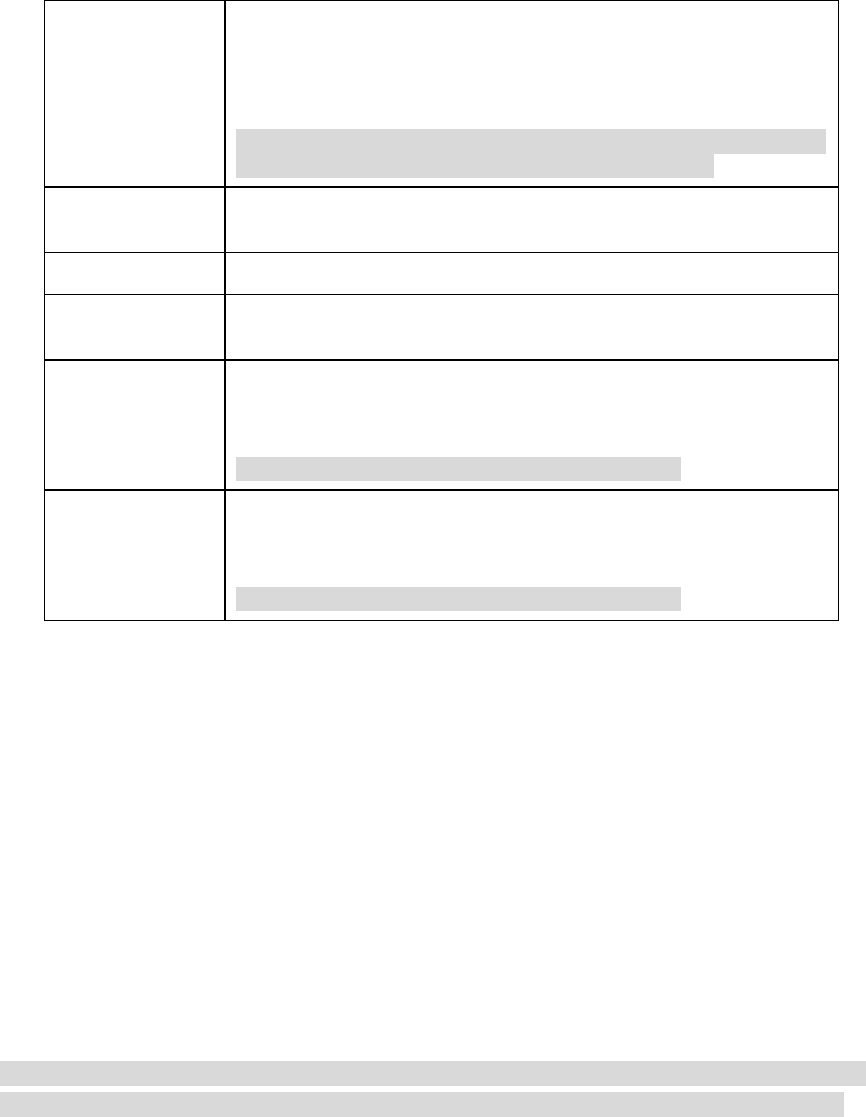
The system displays the interface of “TCP/IP”, which is shown in Figure 4-32.
Figure 4-32
Step 2
Configure TCP/IP parameter, refer to Table 4-12.
Parameter
Function
Host Name
It is to set current host device name. It supports max 15
characters.
Ethernet Card
Please select the Ethernet port. Default is wired.
Please note you can modify the default Ethernet card if there is
more than one card. .
Please note the device needs to reboot to activate the new
setup once you modify the default setup.
Mode
There are two modes: static mode and the DHCP mode. Select
DHCP mode, it auto searches IP, and you cannot set IP/subnet
mask/gateway. Select static mode, you must manually set
IP/subnet mask/gateway.
Mac Address
It is to display device Mac address.
IP Version
It is to select IP version. IPV4 or IPV6.
You can access the IP address of these two versions.
IP Address
Please use the keyboard to input the corresponding number to
modify the IP address and then set the corresponding subnet
mask and the default gateway.

57
Subnet mask
It has to set according to the actual situation, the prefix of
subnet is number, input from 1 to 255, the prefix of subnet
identifies a specific network link, and usually it includes a
layering structure.
Default gateway
Make sure it has to be in the same
segment with IP address according to the
actual situation.
Note
It inputs 128 bit
for IP address,
default gateway,
preferred DNS,
alternate DNS of
IPv6 version, it
can’t be null.
Preferred DNS
DNS server IP address.
Alternate DNS
Alternate IP address of DNS server.
Enable
ARP/Ping to set
device IP
address service.
Check, you can use ARP/Ping command to modify or set the
device IP address if you know the device MAC address.
When it is enabled by default, ping packet can set device IP via
specific length within 2 minutes during device reboot, the
service is off 2 minutes later, the service will be closed
immediately after setting IP successfully. Ping packet can’t set
IP if it is not enabled.
Table 4-12
Step 3
Click “Save” to complete setting.
An example of setting device IP via ARP/Ping
Step 1
Get an unoccupied IP address, and make sure the device and PC are in the same LAN.
Step 2
Get the physical address of the device from the label.
Step 3
Input the following commands in the PC.
System
Command
Windows syntax
Arp -s <IP Address> <MAC>
Ping -l 480 -t < IP Address >
Example:
Arp -s 192.168.0.125 11-40-8c-18-10-11
Ping -l 480 -t 192.168.0.125

58
System
Command
UNIX/Linux/Mac
syntax
Arp -s <IP Address> <MAC>
Ping -s 480 < IP Address >
Example:
Arp -s 192.168.0.125 11-40-8c-18-10-11
Ping -s 480 192.168.0.125
Win7 syntax
netsh i i show in
netsh -c “i i” add neighbors ldx <IP Address> <MAC>
ping -l 480 -t < IP Address >
Example:
netsh i i show in
netsh -c “i i” add neighbors 12 192.168.0.125 11-40-8c-18-10-11
ping -l 480 -t 192.168.0.125
Table 4-13
Step 4
Power off and reboot the device or reboot the device via network.
Step 5
Check the similar info like “Reply from 192.168.0.125…” from the PC command line, then it can set
successfully; you can close the command line.
Step 6
Open the browser and then input http://<IP address>. Click the Enter button, you can access now.
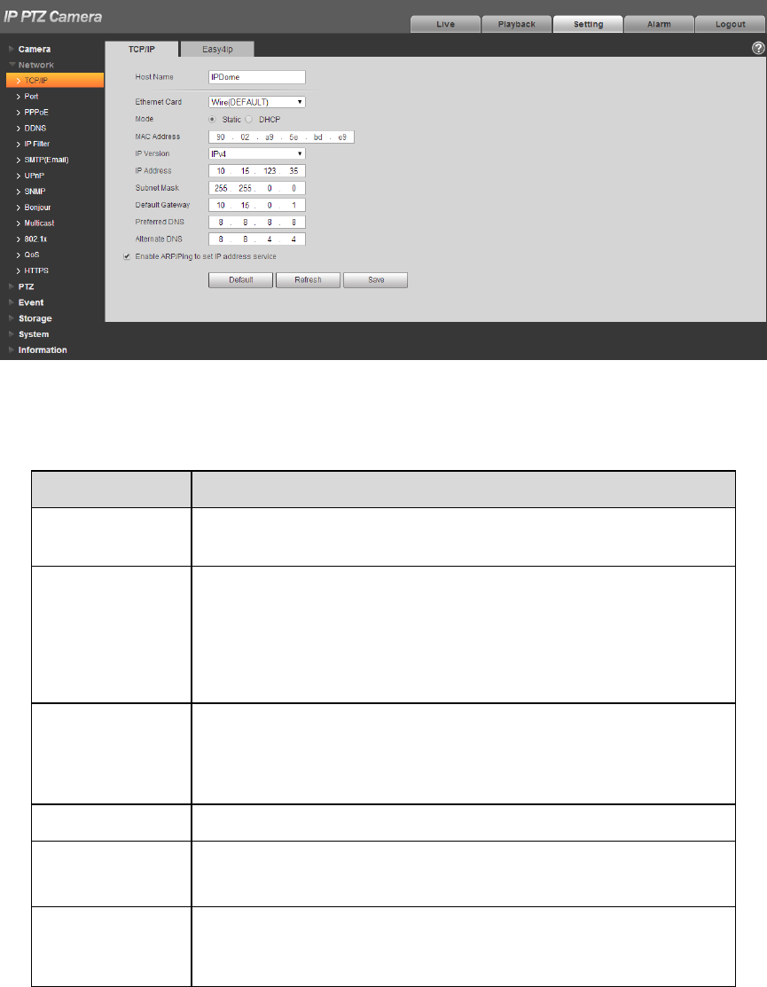
4.2.1.2 Easy 4ip
Easy 4ip module is mainly used to visit device via serial number, it doesn’t need to set IP address, plug
and play, and scan QR code to log in the device.

60
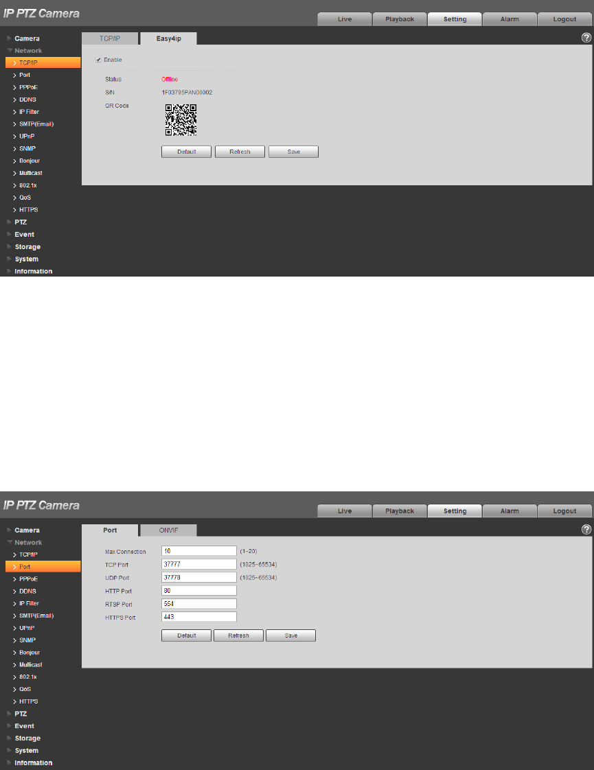
Step 2
Configure each port value of the device; refer to Table 4-14 for more details.
Parameter
Function
Max
connection
It is the max Web connection for the same device. The value ranges from 1
to 20. Default connection amount is 10.
TCP port
Port range is 1025~65534. The default value is 37777. You can input the
actual port number if necessary.
UDP port
Port range is 1025~65534. The default value is 37778. You can input the
actual port number if necessary.
HTTP port
Port range is 1025~65524. The default value is 80. You can input the
actual port number if necessary.
RTSP port
The default value is 554. Please leave blank if use default. User uses
QuickTime or VLC can play the following formats. BlackBerry can play
too.
Real-time monitoring URL format, please require real-time RTSP
media server, require channel no., bit stream type in URL. You may
need username and password.
User uses BlackBerry need to set encode mode to H.264B, resolution
to CIF and turn off audio.
URL format is:
rtsp://username:password@ip:port/cam/realmonitor?channel=1&subtype=0
username/password/IP and port.
The IP is device IP and the port default value is 554. You can leave it in
blank if it is the default value.
Follow standard RTP protocol and when encode mode is MJPEG; the max
resolution only supports 2040*2040.
HTTPs
Enable
Check HTTPs enable, login as https://ip:port. Protect data. Default port is
https://ip . It is disabled by default.
HTTPs
Port
HTTPs communication port, range is 1025~65534, default is 443.
Table 4-14
Note
Except “max connection”, it needs to reboot the device to make it valid after modifying other parameter
config.
Step 3
Click “Save” to complete setting.
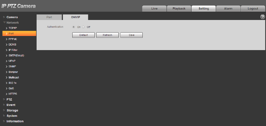
4.2.2.2 ONVIF
61
ONVIF (Open Network Video Interface Forum) describes network video model, port, data type and data
switch modes. ONVIF standard targets to create a network video frame protocol that communicates
network video products from different manufacturers.
Step 1
Select “Setup > Network > Connection > ONVIF”.
The system will display the interface of “ONVIF”, which is shown in Figure 4-35.
Figure 4-35
Step 2
Set “Authentication” as “Enable”.
Step 3
Click “Save” to complete setting.
4.2.3 PPPoE
It can set up network connection via enabling PPPoE (Point-to-Point Protocol over Ethernet) dial mode;
the device will acquire a dynamic IP address of WAN. Please gain the PPPoE username and password
provided by ISP (Internet service provider).
Step 1
Select “Setup > Network > PPPoE”.
The system will display the interface of “PPPoE”, which is shown in Figure 4-36.
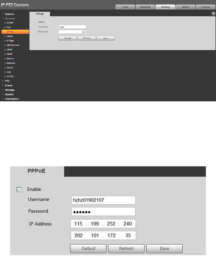
62
Figure 4-36
Step 2
Check “Enable” and input PPPoE username and password.
Step 3
Click “Save” to complete PPPoE config.
The system will prompt that it has been successfully saved and real-time display the acquired IP
address of WAN, which is shown in Figure 4-37, users can visit the device via the IP address.
Figure 4-37
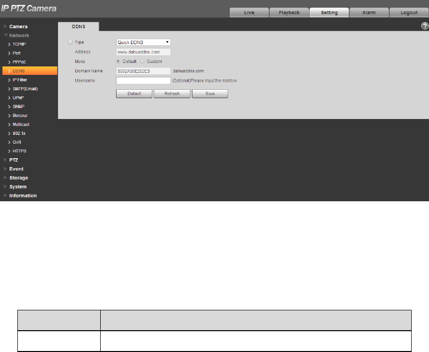
4.2.4 DDNS
63
DDNS (Dynamic Domain Name Server) can be used to update the relationship between domain name
on the DNS server and IP address dynamically in the situation where the device IP address changes
frequently, which is to guarantee the users to visit device via domain name.
Note
Please confirm if the device supports the type of DNS before config and log in the website of DDNS
service provider to register domain name and other info.
If DDNS type is Quick DDNS, then it doesn’t need to register domain name.
If DDNS type is other type, then it needs to log in corresponding DDNS website to register
username, password, domain name and etc.
Users can check info of all the connected devices after they successfully registered in DDNS
website and logged in.
Step 1
Select “Setup > Network > DDNS”.
The system will display the interface of “DDNS”, which is shown in Figure 4-38.
Figure 4-38
Step 2
Check “Server Type” and configure relevant parameter of DDNS according to the actual situation.
Please refer to the following sheet for configuring DDNS parameter if users select DDNS type as
“Quick DDNS”.
Parameter
Function
Server Type
The default “Server Address” is “www. Quickddns.com”.

64
Parameter
Function
Server Address
DDNS server IP address.
CN99DDNS
Server address: www.3322.org
NO-IPDDNS
Server address: dynupdate.no-ip.com
DyndnsDDNS
Server address: members.dyndns.org
QUICK DDNS
Server address: www.quickddns.com
Mode
It is auto by default, manual is optional.
Domain Name
It is “MAC address. quickddns.com” by default in both auto and
manual mode, users can set prefix by themselves.
Test
It is to test if the domain name is available. The parameter
appears only when selecting “Mode” as “Manual”.
Username
The user name you input to log in the server. It is optional.
Table 4-15
1. After filling in the interface, click “Test” to confirm if the domain name can be successfully registered.
If it is successful, please continue to 2, if not, please check if the domain name info is correct and
clear browser cache.
2. Click “Save”.
3. Input complete domain name in the PC browser and press enter.
It means successful config if it can display the device WEB interface; it means config failure if it fails
to display the interface, please configure again.
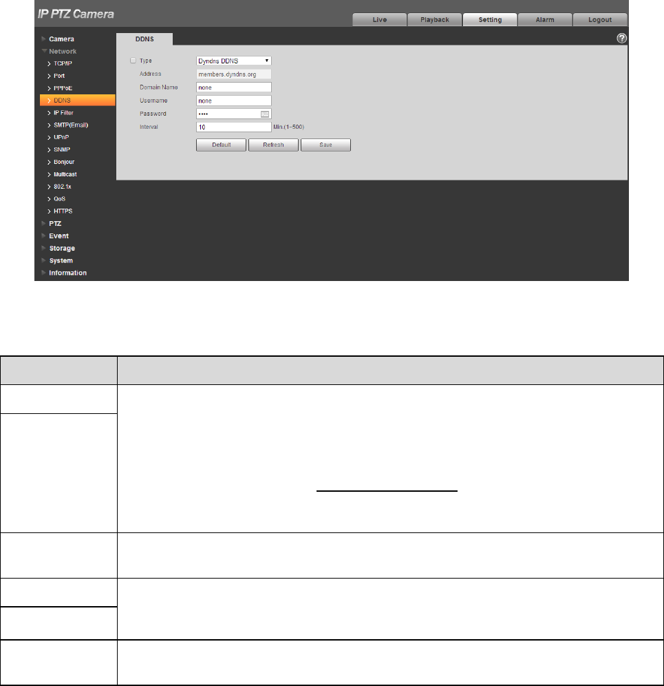
Please refer to the following sheet to configure parameter if it selects other types of DDNS.
65
Figure 4-39
Please refer to the following sheet for detailed information.
Parameter
Function
DDNS Type
The names and addresses of DDNS server provider are listed below:
Dyndns DDNS address is:members.dyndns.org
NO-IP DDNS address is:dynupdate.no-ip.com
CN99 DDNS address is:members.3322.org
PRIVATE DDNS address is:www.privateddns.com, as for private DDNS server,
the port number can be configured according to its actual situation, which can
realize device access with the mode of domain name + port number
Server address
Domain Name
It is the domain name that the users register on the website of DDNS server
provider.
Username
Input the username and password which are acquired from DDNS server provider.
The users need to register account on the website of DDNS server provider
(including username and password)
Password
Interval
After the designated DDNS is updated and enabled, it will launch the interval of
update requirement regularly, the unit is minute.
1. Click “Save” after filling in the interface.
2. Input domain name in the PC browser and press “Enter” button.
It means successful config if it can display the device WEB interface; it means config failure if it
doesn’t display.
66
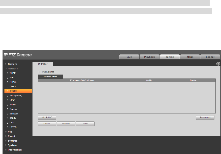
4.2.5 IP filter
It can set the users who are allowed to visit the device via IP filter.
Trusted Sites: It is to add the users’ IP/MAC which can log in the device. If the users check the
trusted sites, then only the users’ IP/MAC which is in the list can log in the device; if trusted sites in
not checked, then there is no restriction for the users who visit the device.
Banned List: It is to add the users’ IP/MAC which refuses to log in the device. If the users check the
banned list, then except the IP/MAC in the banned list, the other users’ IP/MAC can log in the
device.
Users are not allowed to set the device IP/MAC as trusted sites.
MAC verification can be valid only when the device IP and PC’s IP are in the same LAN.
Note
MAC verification can only be restricted according to the router’s MAC when visiting WAN.
Some models don’t support banned list, please refer to the actual product for more details.
Step 1
Select “Setup > Network > IP Filter”.
The system will display the interface of “IP Filter”, which is shown in Figure 4-40.
Figure 4-40
Step 2
Check corresponding check box to enable trusted sites and banned list.
Check “Trusted Sites”, click it and add trusted sites.
Step 3
Click “Add IP/MAC”, and configure IP address info according to Table 4-16.
67
Parameter
Note
IP address
Input the IP address of host which is to be added.
IP segment
Input the start address and end address of the segment which is to be
added.
IPv4
IP address adopts IPv4 format, such as 172.16.5.10
IPv6
IP address adopts IPv6 format, such as aa:aa:aa:aa:aa:aa:aa:aa.
MAC
Input the MAC address of host which is to be added.
Table 4-16
Step 4
Click “Save” to make config valid.
Use the IP host in the trusted sites to log in device WEB interface, which can realize successful device
login.
Check “Banned List”, click it to add banned list.
1. Complete adding banned list according to the sheet above.
Note
Add banned list, but it doesn’t support adding MAC address.
2. Click “Save” to make config valid.
Use the IP host in the banned list to log in the device WEB interface. The system prompts that it has
been added into banned list, and it fails to log in.
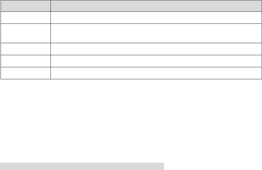
4.2.6 SMTP (e-mail)
By setting SMPT, it will send email immediately when alarm, video detection and abnormity happen.
When alarm, video detection and abnormity trigger, it can send email to the server of the receiver via
SMPT server. The receiver can receive the email when logging in the server.
Step 1
Select “Setup > Network > SMPT”.
The system will display the interface of “SMPT”, which is shown in Figure 4-41.
68
Figure 4-41
Step 2
Configure info of each parameter according to the actual needs.
Parameter
Function
SMTP Server
Conform to SMTP protocol; send the IP address of email
server.
Port
Conform to SMTP protocol; send the port number of email
server, it is 25 by default.
Anonymity
For the server supports the anonymity function. You can auto
login anonymously. You do not need to input the user name,
password and the sender information.
User Name
The user name of the sender email account.
Password
The password of sender email account.
Sender
Sender email address.
Authentication
(Encryption
mode)
You can select SSL, TLS or none.
Title
Email title, and it can be customized.
Attachment
System can send out the email of the snapshot picture once
you check the box here.
Mail receiver
Input receiver email address here. Max three addresses.

69
Parameter
Function
Interval
The send interval ranges from 0 to 3600 seconds. 0 means
there is no interval.
Please note system will not send out the email immediately
when the alarm occurs. When the alarm, motion detection or
the abnormity event activates the email, system sends out the
email according to the interval you specified here. This
function is very useful when there are too many emails
activated by the abnormity events, which may result in heavy
load for the email server.
Health mail
enable
Please check the box here to enable this function.
Email test
The system will automatically sent out an email once to test
the connection is OK or not .Before the email test, please
save the email setup information.
Table 4-17
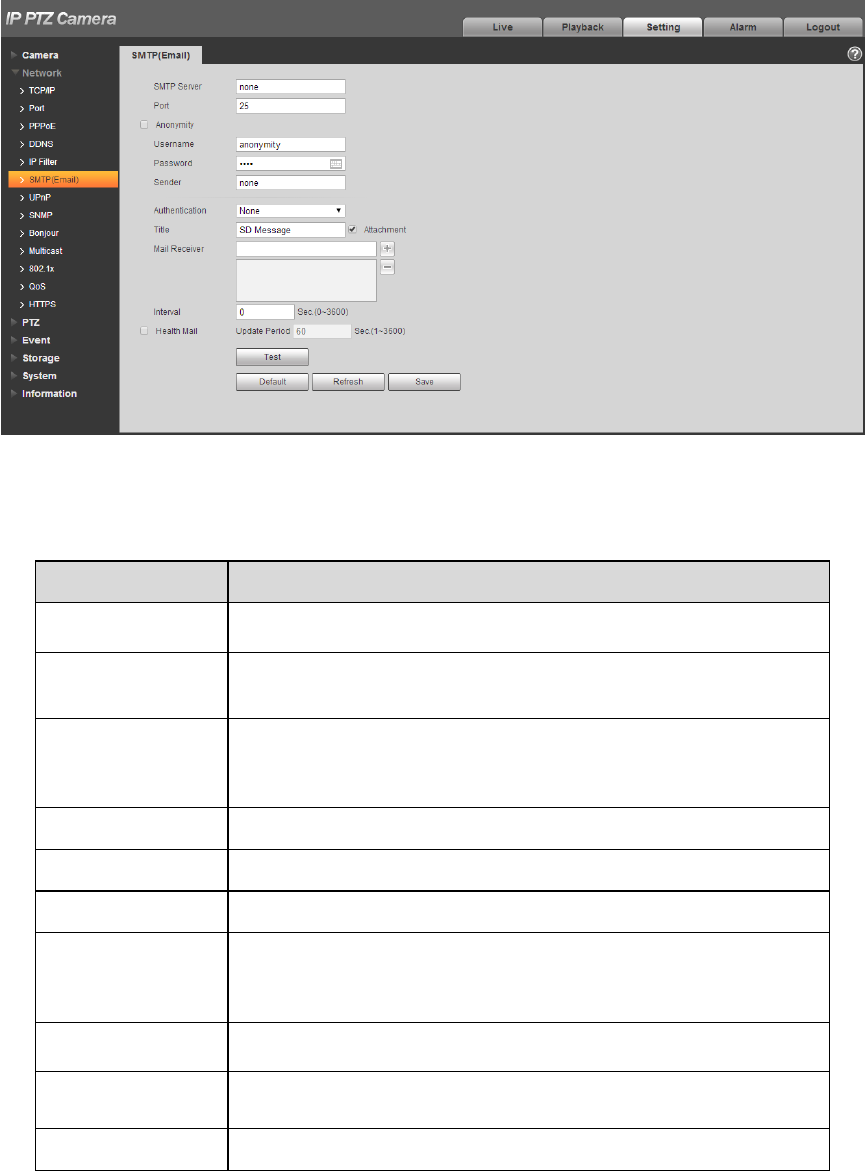
4.2.7 UPnP
It allows you to establish the mapping relationship between the LAN and the public network.
Here you can also add, modify or remove UPnP item. For UPnP on different routers, you must disable
UPnP function.
Enable UPnP, network cameras support UPnP protocol. In Windows Xp or Windows Vista system, if
system UPnP is enabled, then the network camera can auto search it in the network neighborhood of
Windows.
Please refer to the following steps to install UPnP network service in the Windows system:
Step 1
Open control panel, and select “Add or Remove Programs”.
Step 2
Click the “Add/Remove Windows Components”
Step 3
Select the “Network Services” from the Windows Components Wizard. Click the Details button
Step 4
Check the “Internet Gateway Device Discovery and Control client” and “UPnP User Interface”. Please
click OK to begin installation.
The operation steps of UPnP config is shown as follows:
Step 1
Select “Setup > Network > UPnP”.
The system will display the interface of “UPnP”, which is shown in Figure 4-42.
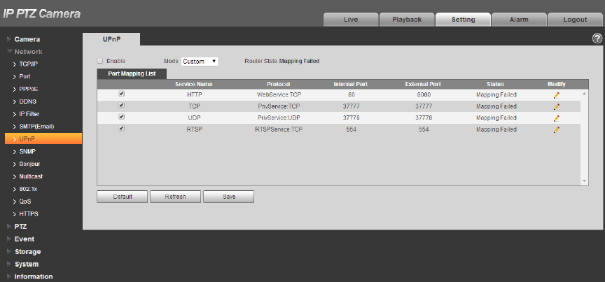
70
Figure 4-42
Step 2
Check the box and enable UPnP function.
Step 3
Selection mode
There are two mapping modes for UPnP which are auto and manual. As for manual mapping mode, it
allows users to modify external port; as for auto mapping mode, it completes port mapping automatically
without occupying the port, and users don’t need to modify mapping.
Step 4
Click “Save” to make config valid.
4.2.8 SNMP
The SNMP (Simple Network Management Protocol) provides framework of bottom-layer network
management for network management system. It can control SNMP function in the network service
setting. It can gain the relevant config info after connecting to device via relevant software tool. It needs
to satisfy the following conditions if it is to use SNMP function:
Install SNMP device monitoring and management tool, such as MIB Builder and MG-SOFT MIB
Browser.
Get two MIB documents which are corresponding to the current version from technical personnel.
Step 1
Select “Setup > Network > UPnP”.
The system will display the interface of “SNMP”, which is shown in Figure 4-43 and Figure 4-44
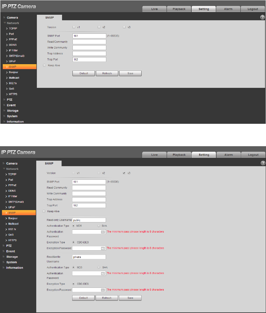
71
Figure 4-43
Figure 4-44
Step 2
Configure info of each parameter according to the actual needs.

72
Parameter
Function
SNMP Version
Check SNMP v1, device can only process v1 info.
Check SNMP v2, device can only process v2 info.
Check SNMP v3, can set username, password and
encryption method. Server calibrate corresponding
username, password and encryption method too access
device and v1/v2 are unavailable.
SNMP port
The listening port of the proxy program of the device. It is a
UDP port not a TCP port. The value ranges from 1 to 65535.
The default value is 161
Community
It is a string, as command between management and proxy, ,
defining a proxy, and a manager’s authentication.
Read community
Read-only access to all SNMP targets, default is public.
Note: Only number, letter, _, and – supported.
Write community
Read/write access to all SNMP targets, default is private.
Note: Only number, letter, _, and – supported.
Trap address
The destination address of the Trap information from the
proxy program of the device.
Trap
SNMP trap is a proxy message sent to admin as important
event notice or status change.
Trap Port
Port which send Trap message, default is 162, range
1~65535.
Read-only
Username
Default is public.
Note:
Name only can be number, letter and underline.
Read/Write
Username
Default is private.
Note:
Name only can be number, letter and underline.
Authentication
You may select MD5 or SHA, default is MD5.
Authentication
Password
Password not less than 8 characters.
Encryption
Default is CBC-DES.
Encryption
Password
Password not less than 8 characters.
Table 4-18
Step 3
Click “Save” to make config valid.
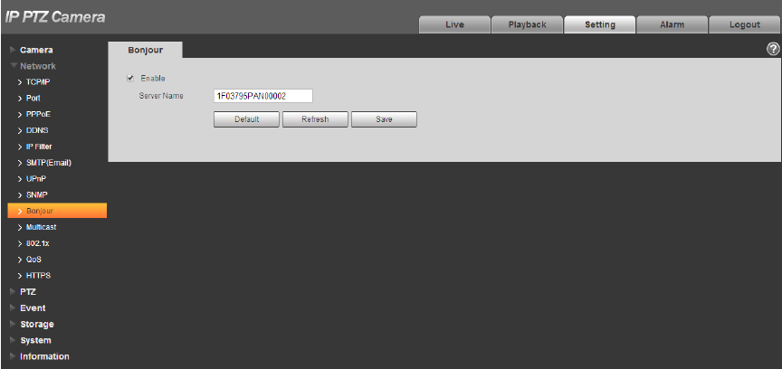
73
4.2.9 Bonjour
Bonjour, known as zero config networking, can auto discover the PC, device and service on the IP
network. Bonjour uses the IP protocol with industrial standard to allow the device to discover each other
automatically without inputting IP address or configuring DNS server.
After Bonjour function is enabled, the network cameras will be auto detected in the operating system
and client which support Bonjour. When the network camera is auto detected by Bonjour, it will display
the “Server Name” which is configured by users.
Step 1
Select “Setup > Network > Bonjour”.
The system will display the interface of “Bonjour”, which is shown in Figure 4-45.
Figure 4-45
Step 2
Check “Enable” to set server name.
Step 3
Click “Save” to make config valid.
In the operating system and client which support Bonjour, it can visit network camera WEN interface via
Safari browser, the steps are as follows:
Step 1
Click Safari browser “Display All Bookmarks”.
Step 2
Open “Bonjour”, and it can auto detect the network camera which enables Bonjour function in the LAN.
Step 3
Click it to visit corresponding WEB page.
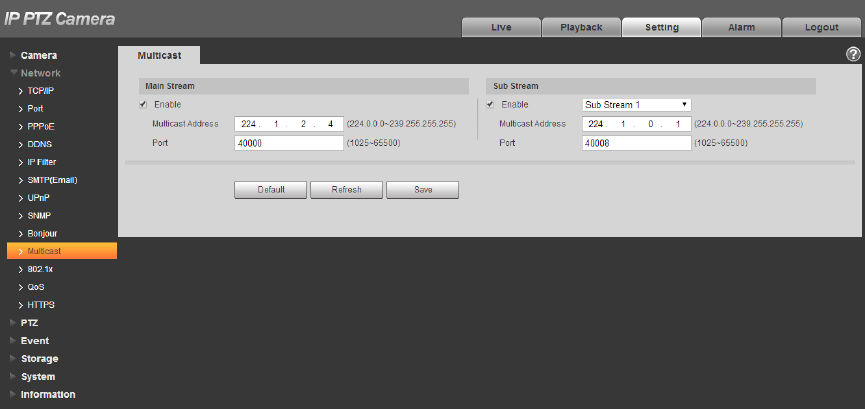
74
4.2.10 Multicast
Preview video image via network device visit, it will fail to preview video image if it exceeds the visit
upper limit of the device, at this moment you can solve the problem by adopting multicast protocol visit
via setting multicast IP to the device.
Step 1
Select “Setup > Network > Multicast”.
The system will display the interface of “Multicast”, which is shown in Figure 4-46.
Figure 4-46
Step 2
Check “Enable” to enable multicast.
Step 3
Input multicast address and port.
Step 4
Click “Save” to complete config.
4.2.11 802.1x
802.1x (port based network access control protocol) supports manual selection of authentication
method to control if device connected to LAN can join the LAN. It well supports authentication, charging,
safety and management requirement of network.
Step 1
Select “Setup > Network > 802.1x”.
The system will display the interface of “802.1x”, which is shown in Figure 4-47.
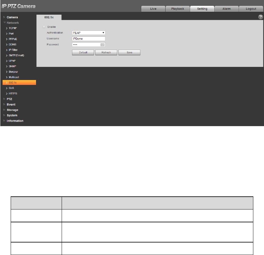
75
Figure 4-47
Step 2
Check “Enable” to enable 802.1x.
Step 3
Select authentication mode, set username and password.
Please refer to Table 4-19 for detailed information.
Parameter
Function
Authentication
PEAP (protected EAP protocol).
Username
It needs the username to login, which is authenticated by the
server.
Password
Please input password here.
Table 4-19
Step 4
Click “Save” to complete config.
4.2.12 QoS
QoS (Quality of Service) is network security mechanism. It is a technology to fix the network delay and
jam problem and etc. For the network service, the quality of service includes the transmission bandwidth,
delay, the packet loss and etc. We can guarantee the transmission bandwidth, lower the delay, and
reduce the loss of the data packet and anti-dither to enhance the quality.
We can set the DSCP (Differentiated Services Code Point) of the IP to distinguish the data packet so
that the router or the hub can provide different services for various data packets. It can select the
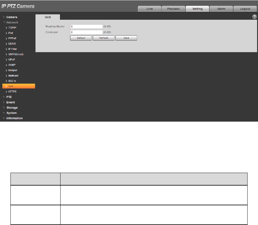
76
different queues according to the priority (64 different priority levels) of the packets and select the
bandwidth of the each queue. Level 0 is the lowest, and level 63 is the highest. It can also discard at the
different ratio when the broad bandwidth is jam.
Step 1
Select “Setup > Network > QoS”.
The system will display the interface of “QoS”, which is shown in Figure 4-48.
Figure 4-48
Step 2
Set realtime monitor and operation command.
Please refer to the following sheet for detailed information.
Parameter
Function
Realtime
monitor
Data packet of network video monitoring, the value ranges from
0 to 63.
Command
Configure or inquire non-monitoring data packet for the device,
the value ranges from 0 to 63.
Table 4-20
Step 3
Click “Save” to complete config.
4.2.13 HTTPs
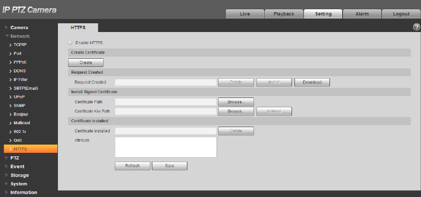
77
In the HTTPs setting interface, users can make PC log in normally via HTTPs by creating certificate or
uploading signed certificate, which is to guarantee the security of communication data and provide
safeguard for user information and device security with reliable and stable technical means.
4.2.13.1 Create Custom Certificate and Install
Step 1
Select “Setup > Network > HTTPs”, and the system will display the interface of HTTPs, which is shown
in Figure 4-49.
Figure 4-49
Step 2
Create certificate.
1. Click “Create” and it will pop out the dialog box of “HTTPs”, which is shown in Figure 4-50.
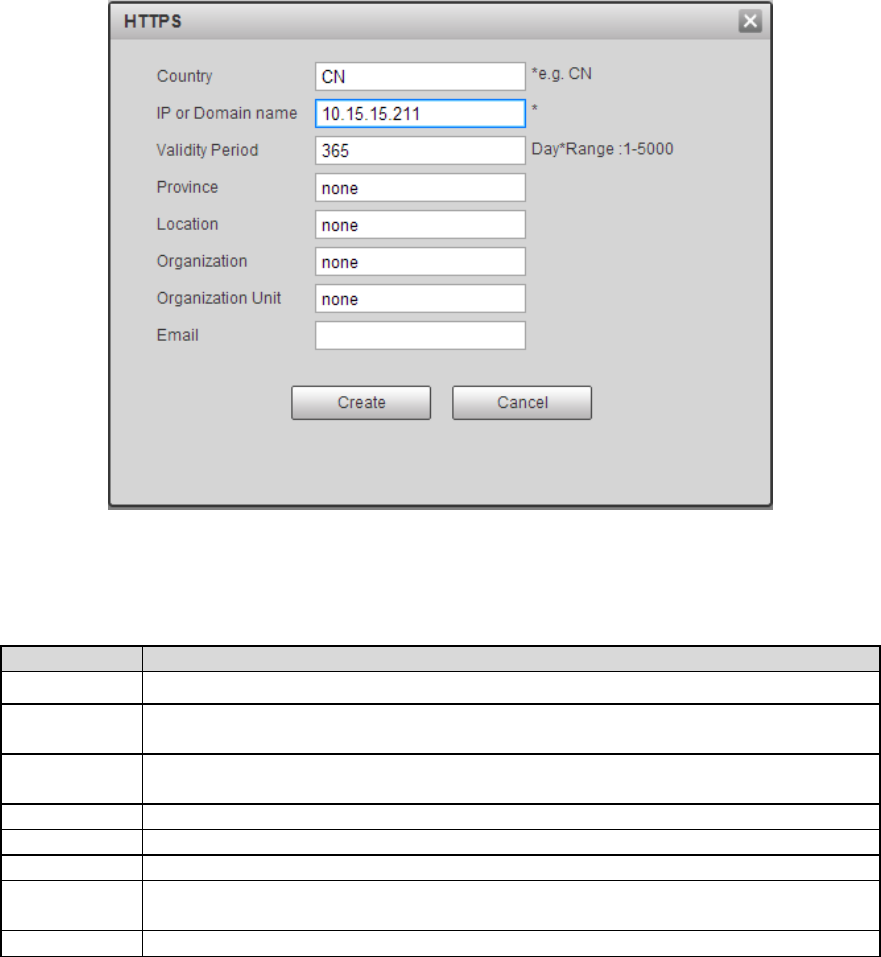
78
Figure 4-50
2. Set HTTPs parameters; please refer to the following table for more details.
Parameter
Note
Country
Country abbreviation. You can only enter 2 capital letters.
IP/Domain
name
Device IP address.
Validity
period
The validity period of certificate
Province
The province which uses the certificate.
Location
The location which uses the certificate.
Organization
The organization which uses the certificate
Organization
unit
The name of organization unit which uses the certificate.
Email
The personal or unit email which uses the certificate.
Table 4-21
3. Click “Create”. It will display the created request in the area of “Request Created” after it
finishes creating.
Step 3
Click “Install”. The system starts to install certificate, it will generate certificate attribute in the area of
“Certificate Installed” after installation is completed.
Note
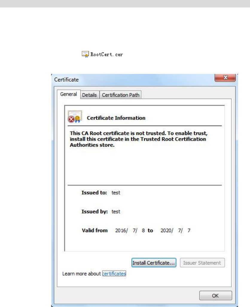
79
Click the “Delete” button of the “Certificate Installed” area to delete the installed certificate.
Step 4
Click “Download” to save the root certificate.
Step 5
Install root certificate.
1. Double click the you have downloaded and the system will pop out the
dialog box of “Certificate”, which is shown in Figure 4-51.
Figure 4-51
2. Click “Install Certificate”. The system will pop out the dialogue box of “Certificate Import
Wizard”, which is shown in Figure 4-52.
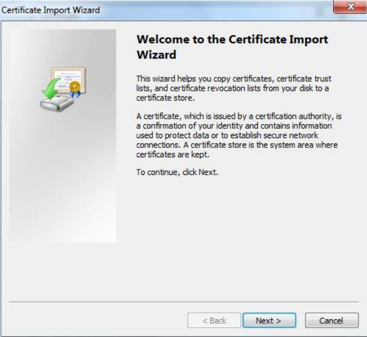

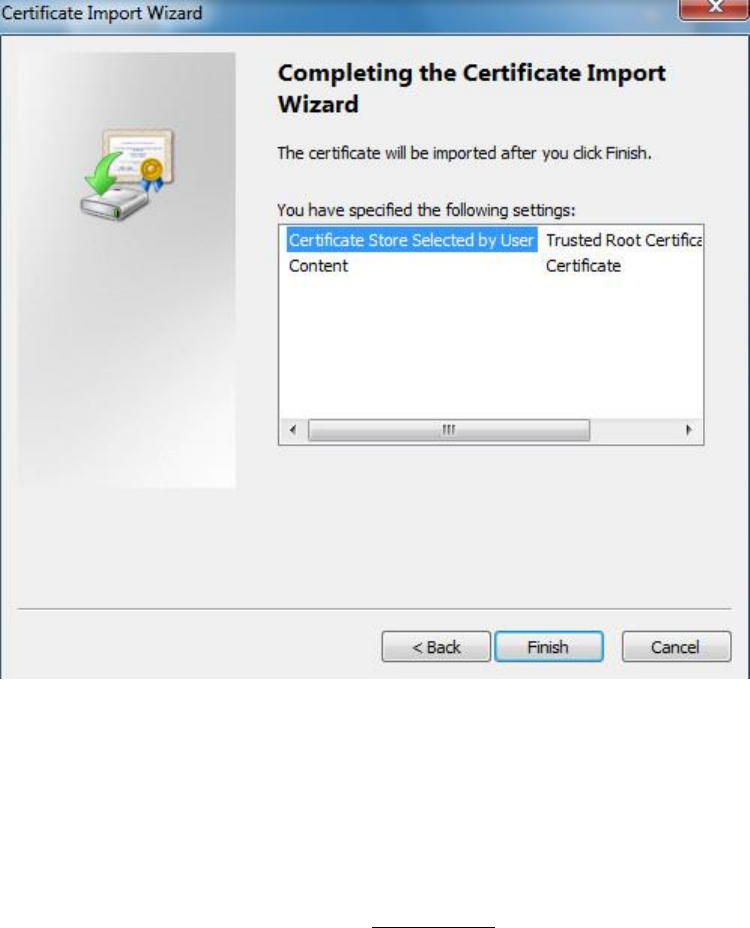
82
Figure 4-54
5. Click “Finish”. The system will pop out the dialog box of “Security Warning”, click “Yes” and
the system will pop out the prompt of “The Import is successful”, click “OK” to complete
certificate import.
6. Click “OK” to complete root certificate installation.
Step 6
Click “Save” and the device begins to reboot. Enter https://device IP address in the browser and make
access to the device via HTTPs after the device is rebooted.
4.2.13.2 Install Signed Certificate
It can import signed certificate and certificate secret key after acquiring signed certificate and certificate
secret key from the digital signature organization.
Step 1
Select “Setup > Network > HTTPs”. The system will display the interface of “HTTPs”, which is shown in
Figure 4-55.
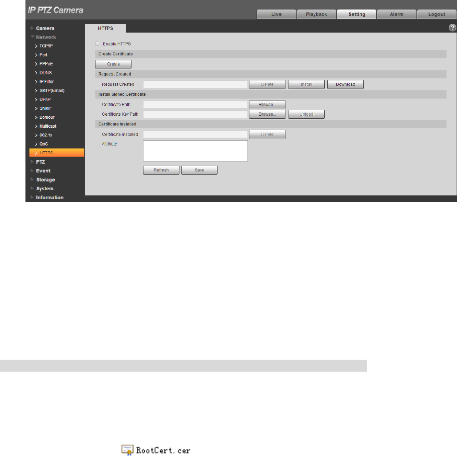
83
Figure 4-55
Step 2
Click the “Browse” which is corresponding to “Certificate Path”, select the signed certificate; click the
“Browse” which is corresponding to “Certificate Key Path”, select the corresponding secret key file of
signed certificate.
Step 3
Click “Upload” and the system begins to install certificate, it will generate certificate attribute in the area
of installed certificate after installation is completed.
Note
Click “Delete” of the “Installed Certificate” area to delete the installed certificate.
Step 4
Click “Download” to save root certificate.
Step 5
Install root certificate.
1. Double click which has been downloaded. The system will pop out the
dialog box of “certificate”, which is shown in Figure 4-56.
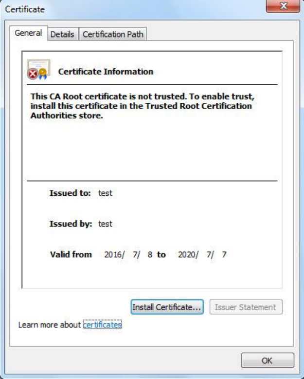

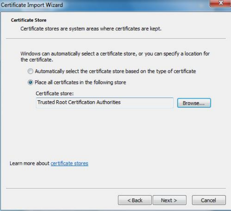
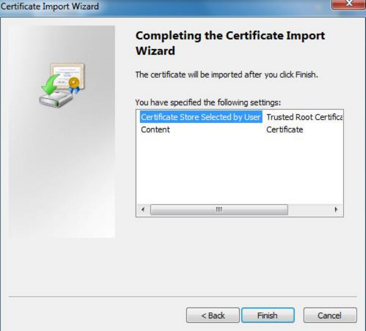
87
Figure 4-59
5. Click “Finish”, and it will pop out the dialog box of “Security Warning”, click “Yes” and the
system will pop out the prompt of “The import was successful”, click “OK” to complete
certificate import. Please refer to Figure 4-60 and Figure 4-61 for more details.
6. Click “OK” to complete root certificate installation.
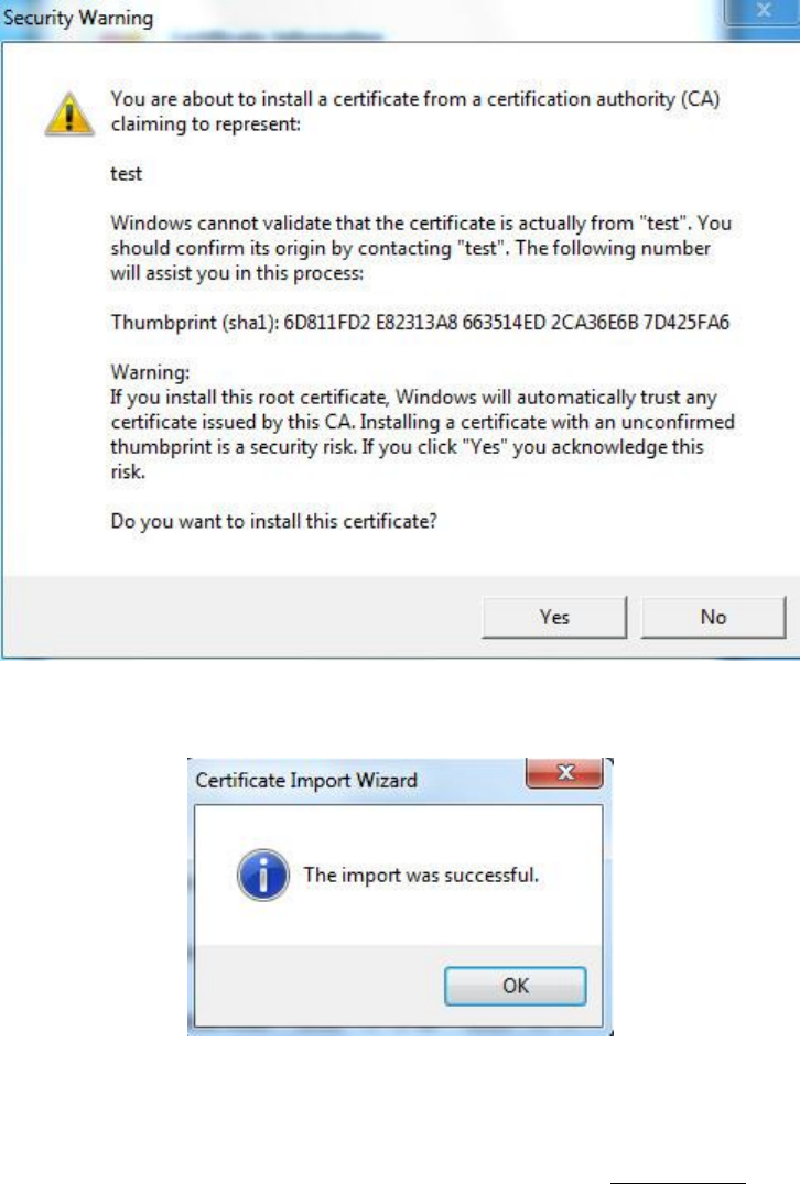
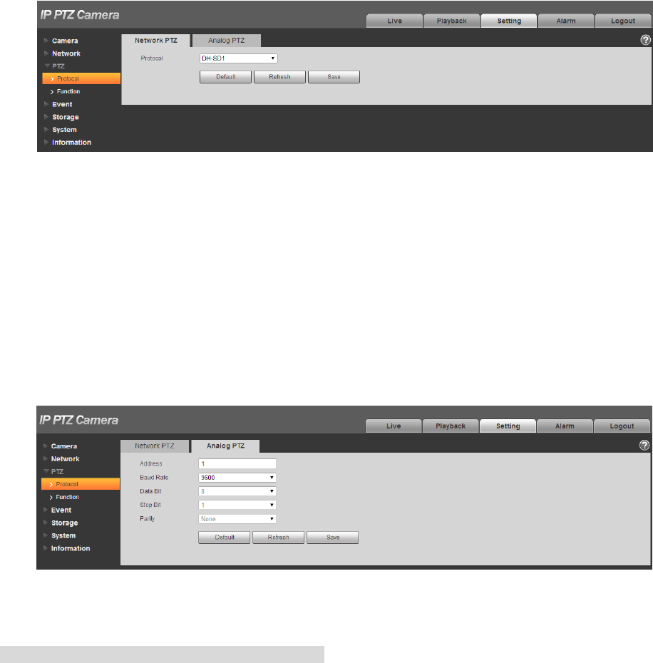
89
4.3 PTZ Setting
4.3.1 Protocol
4.3.1.1 Network PTZ
Step 1
Select “Setup > PTZ Setting > Protocol > Network PTZ”.
The system will display the interface of “Network PTZ”, which is shown in Figure 4-62.
Figure 4-62
Step 2
Set PTZ protocol.
Step 3
Click “Save” to complete config.
4.3.1.2 Analog PTZ
Step 1
Select “Setup > PTZ Setting > Protocol > Analog PTZ”.
The system will display the interface of “Analog PTZ”, which is shown in Figure 4-63.
Figure 4-63
Note
Some models don’t support analog PTZ function.
Step 2
Configure info of each parameter according to the actual needs; refer to Table 4-22 for more details.
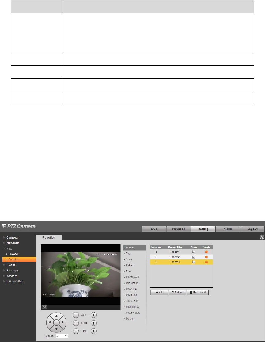
90
Parameter
Function
Address
It is to set corresponding device address.
Note:
Make sure the address is the same as that of the device,
otherwise it will fail to control the device.
Baud Rate
It is to select the baud rate used by the device.
Data Bit
It is 8 by default.
Stop Bit
It is 1 by default.
Parity
It is none by default.
Table 4-22
Step 3
Click “Save” to complete config.
4.3.2 Function
4.3.2.1 Preset
Preset means the current environment in which the camera is located, users can adjust the PTZ and
camera to the environment quickly via calling preset.
Step 1
Select “Setup > PTZ Setting > Function > Preset”.
The system will display the interface of “Preset”, which is shown in Figure 4-64.
Figure 4-64
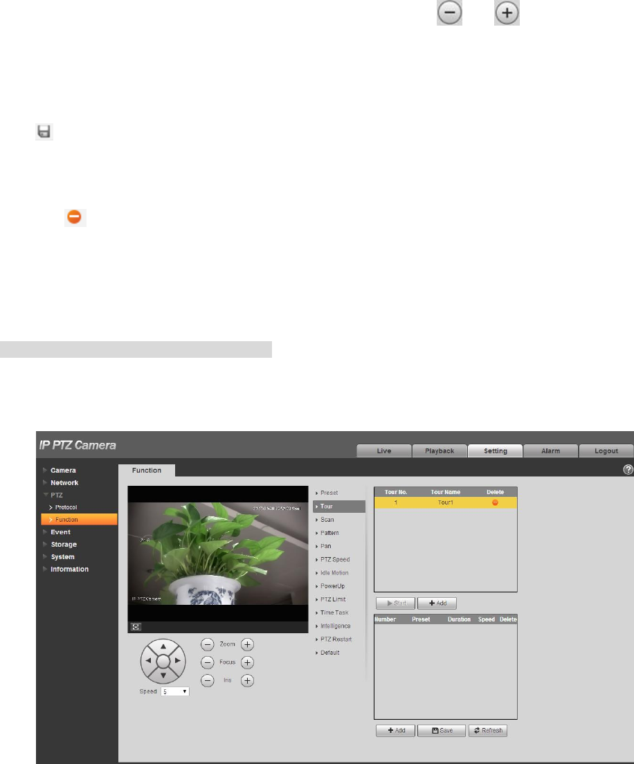
91
Step 2
In the lower left corner of the config interface, click direction button, and to adjust PTZ direction,
zoom, focus and iris size, adjust the camera to a proper monitoring location.
Step 3
Click “Add”. It will add the location as preset in the list, and it will be displayed in the preset list.
Step 4
Click to save the preset.
Step 5
Implement relevant operation upon the preset.
Double click “Preset title” to modify the title to be displayed on the monitoring screen for the preset.
Click to delete the preset.
Click “Clear” to remove all the preset.
4.3.2.2 Tour
Tour can realize auto movement according to the set preset.
Note
It needs to set several presets in advance.
Step 1
Select “Setup > PTZ Setting > Function > Tour”.
The system will display the interface of “Tour”, which is shown in Figure 4-65.
Figure 4-65
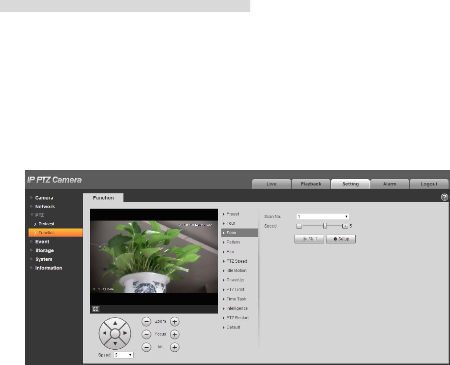
92
Step 2
Click “Add” which is located on the upper right corner of the interface, and then it will add tour path.
Step 3
Click “Add” which is located on the lower right corner, and then it will add several presets.
Step 4
Implement relevant operation upon the tour.
Double click “Tour Name” to modify the name of the tour.
Double click “Duration” to set duration for each preset.
Step 5
Click “Start” to start tour.
Note
The device will stop tour if PTZ is operated during tour.
Step 6
Click “Stop” to stop tour.
4.3.2.3 Scan
Scan means the speed dome scanning back and forth within the left and right limit with a certain speed.
Step 1
Select “Setup > PTZ Setting > Function > Scan”.
The system will display the interface of “Scan”, which is shown in Figure 4-66.
Step 2
Click San No.
Figure 4-66
Step 3
Drag Speed bar and set scan speed.
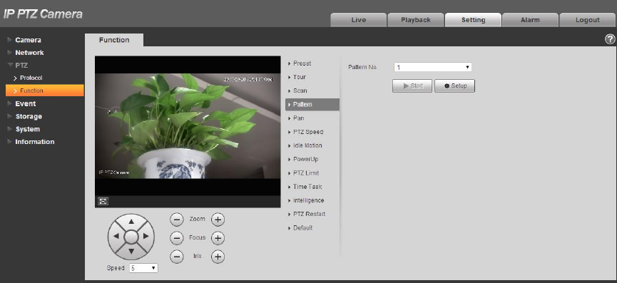
93
Step 4
Click “Setup”, adjust the camera direction to make it reach proper location.
Step 5
Click “Set Left/Right Limit” to set the location as the “Left/Right Limit” of the camera.
Step 6
Click “Start” to start scan.
Step 7
Click “Stop” to stop scan.
4.3.2.4 Pattern
Pattern can continuously record the operations implemented upon the device, such as pan, tilt, zoom,
call preset and etc. You can directly call the pattern after it is saved completely.
Step 1
Select “Setup > PTZ Setting > Function > Pattern”.
The system will display the interface of “Pattern”, which is shown in Figure 4-67.
Figure 4-67
Step 2
Select Pattern No.
Step 3
Click “Setup” and click “Start Rec’, operate the PTZ according to the actual needs.
Step 4
Click “Stop Rec” to complete recording.
Step 5
Click “Start” to start pattern.
Step 6
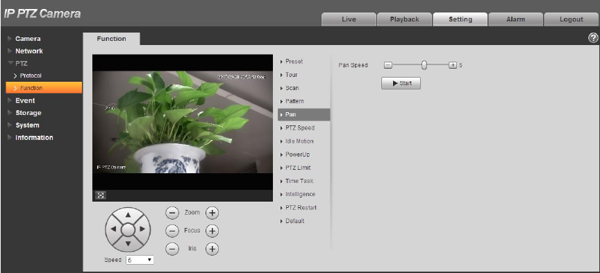
94
Click “Stop” to stop pattern.
4.3.2.5 Pan
Pan means the speed dome rotating continuously 360°horizontally with a certain speed.
Step 1
Select “Setup > PTZ Setting > Function > Pan”.
The system will display the interface of “Pan”, which is shown in Figure 4-68.
Figure 4-68
Step 2
Drag speed bar and set “Pan Speed”
Step 3
Click “Start” to make the PTZ rotate horizontally with the speed you just set.
Step 4
Click “Stop” to stop pan.
4.3.2.6 PTZ speed
PTZ speed means the rotation speed of the device.
Step 1
Select “Setup > PTZ Setting > Function > PTZ Speed”.
The system will display the interface of “PTZ Speed”, which is shown in Figure 4-69.
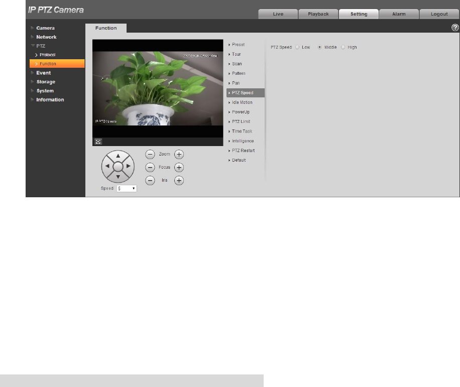
95
Figure 4-69
Step 2
Select “PTZ speed”, it is “Middle” by default.
The system will make the PTZ rotate with the speed you just set.
4.3.2.7 Idle Motion
Idle motion means the device implementing the behavior which is set in advance when it is not receiving
any valid command within the set time.
Note
It needs to set preset, tour, scan and pattern in advance.
Step 1
Select “Setup > PTZ Setting > Function > Idle Motion”.
The system will display the interface of “Idle Motion”, which is shown in Figure 4-70.
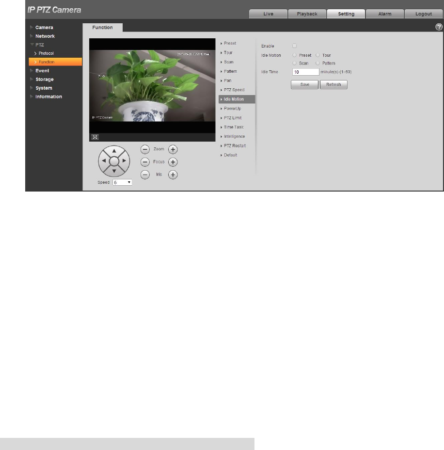
96
Figure 4-70
Step 2
Select “Enable” to enable idle motion function.
Step 3
Select types of idle motion, which are preset, tour, scan or pattern.
Step 4
Select the number of idle motion.
Step 5
Set the idle time of the selected motion.
Step 6
Click “Save” to complete config.
4.3.2.8 Power Up
It means the motion which is auto operated by the device after it is powered up.
Note
It needs to set preset, tour, scan and pattern in advance.
Step 1
Select “Setup > PTZ Setting > Function > Power up”, which is shown in Figure 4-71.
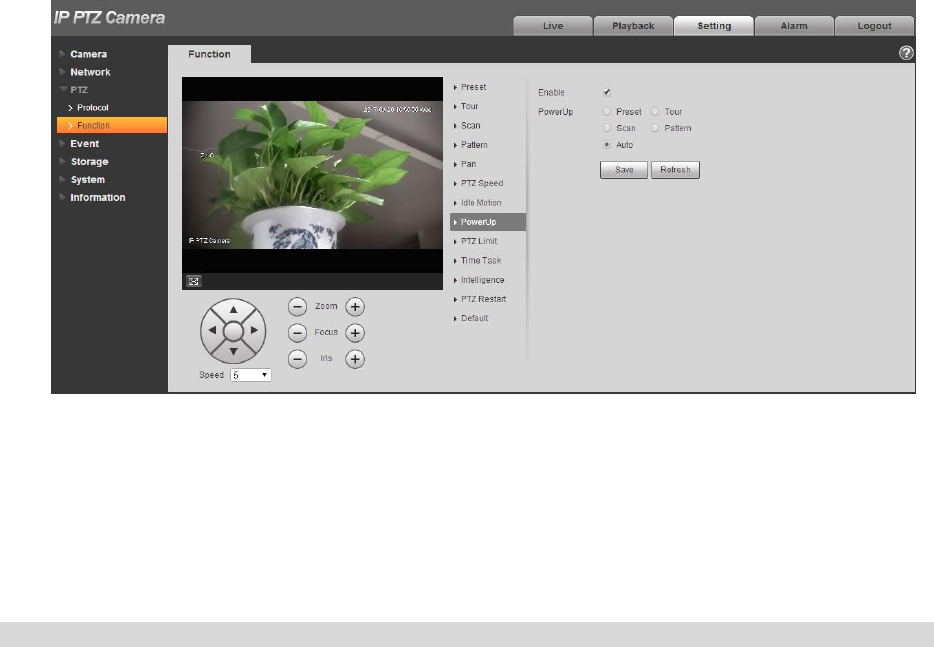
97
Figure 4-71
Step 2
Select “Enable” to enable PowerUp functions.
Step 3
Select the types of PowerUp; you can select preset, tour, scan, pattern or auto.
Note
The system will implement the last action before the camera’s power is cut off when selecting “Auto”.
Step 4
Select the number of action type.
Step 5
Click “Save” to complete config.
4.3.2.9 PTZ Limit
PTZ limit function is used to set the movement area of the device, which makes the device move within
area.
Step 1
Select “Setup > PTZ Setting > Function > PTZ Limit”.
The system will display the interface of “PTZ Limit”, which is shown in Figure 4-72.
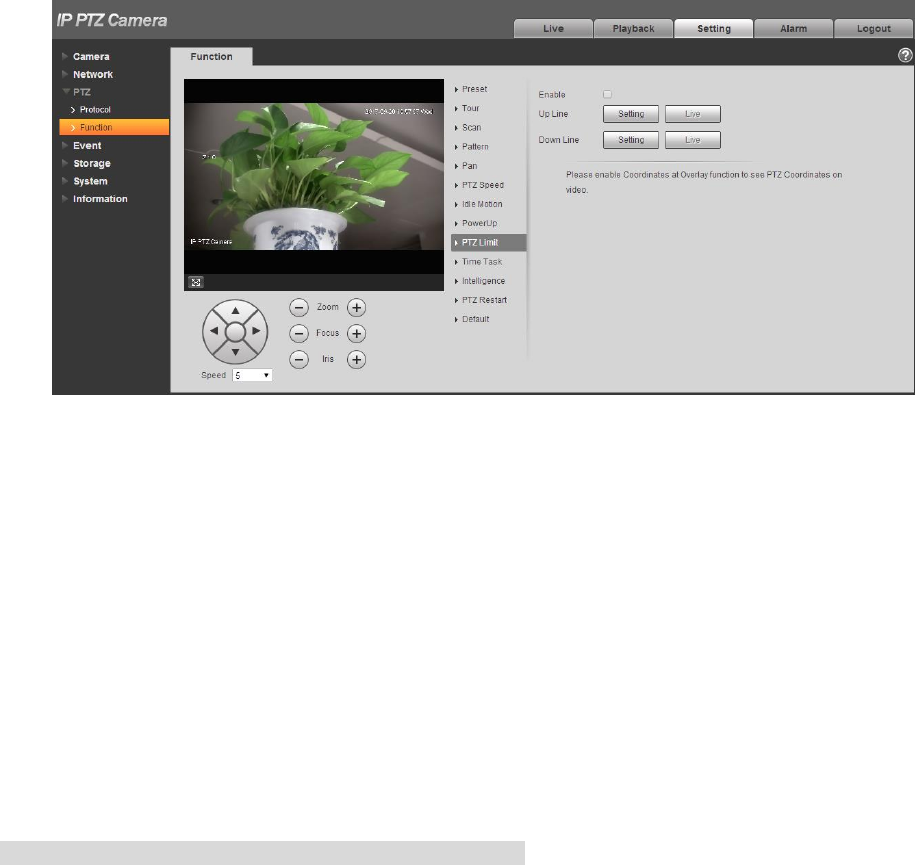
98
Figure 4-72
Step 2
Select “Enable” to enable PTZ Limit function.
Step 3
Control camera direction; click “Setting” to set up line.
Step 4
Control camera direction; click “Setting” to set down line.
Step 5
Click “Live” to preview the up line and down line which is already set.
4.3.2.10 Time Task
Time task is to implement relevant movements within the set period.
Note
It needs to set preset, tour, scan and pattern in advance.
Step 1
Select “Setup > PTZ Setting > Function > Time Task”.
The system will display the interface of “Time Task”, which is shown in Figure 4-73.
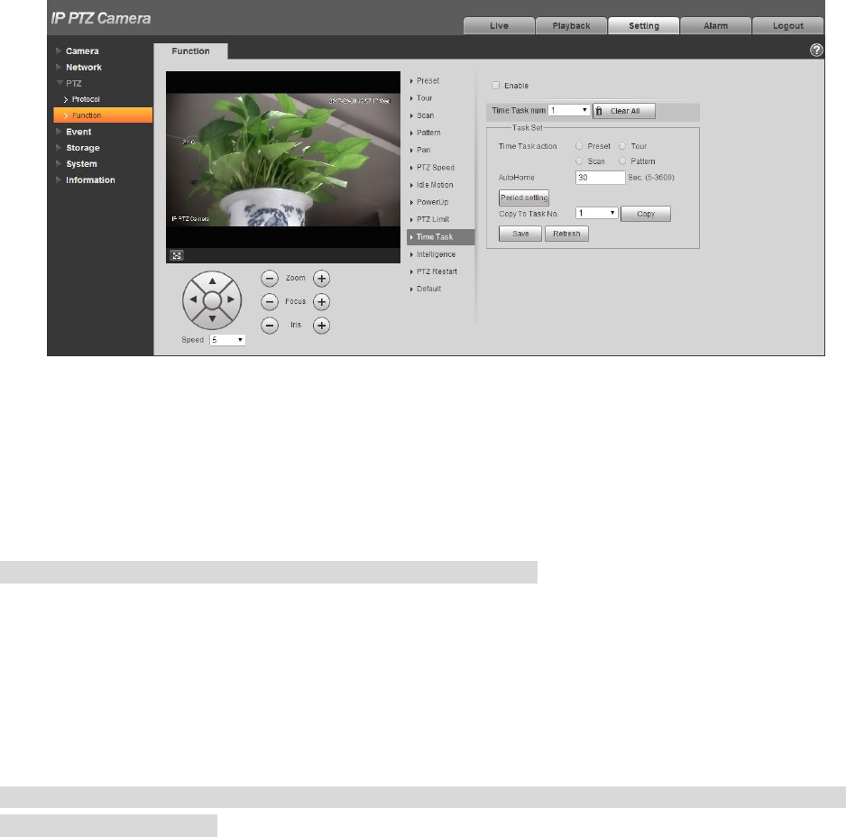
99
Figure 4-73
Step 2
Select “Enable” to enable the function of time task.
Step 3
It is to set the number of time task.
Note
Click “Clear All” to delete all the time tasks which have been set.
Step 4
Select time take action, you can select preset, tour, scan or pattern.
Step 5
Select action number.
Step 6
Set the time of auto home.
Note
Auto home time means the time it needs to take to auto recover time task when manually calling PTZ
and interrupting time task.
Step 7
Click “Period Setting” to set the period of implementing time task.
Step 8
Click “Copy” and select task number, then you can copy it to the task whose number has been selected.
Step 9
Click ‘Save” to complete config.
4.3.2.11 Intelligence
It is to set the tracking duration of the camera. The config steps are shown as follows:
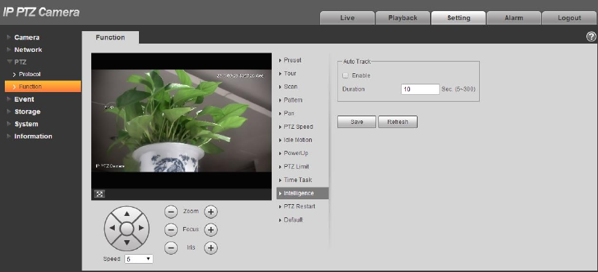
100
Step 1
Select “Setup > PTZ > Function > Intelligence” and the system will display the interface of “Intelligence”,
which is shown in Figure 4-74.
Figure 4-74
Step 2
Select “Enable” to enable auto tracking function.
Step 3
Input the duration of auto tracking.
Step 4
Click “Save” to complete config.
4.3.2.12 PTZ Restart
Step 1
Select “Setup > PTZ Setting > Function > PTZ Restart”.
The system will display the interface of “PTZ Restart”, which is shown in Figure 4-75.
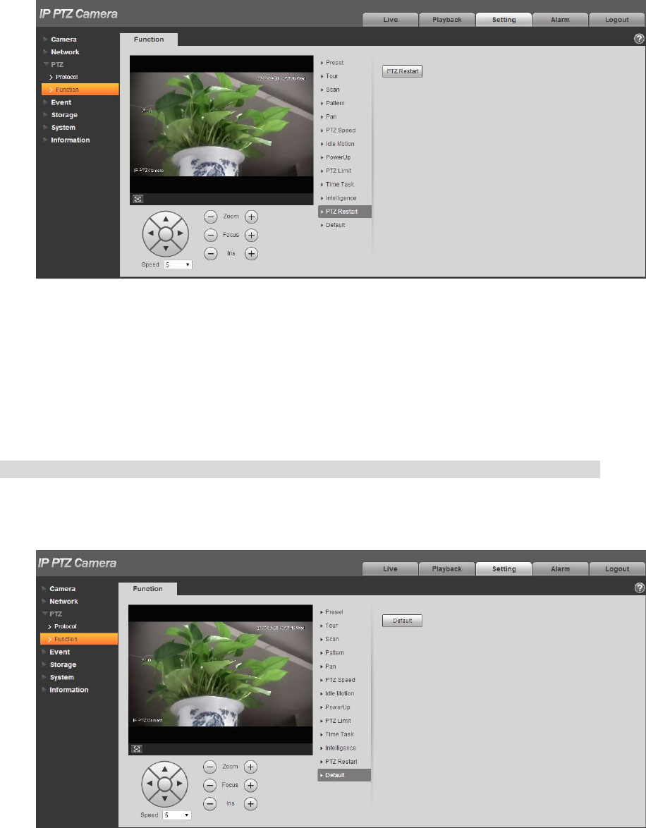
101
Figure 4-75
Step 2
Click “PTZ Restart” and the system will restart PTZ.
4.3.2.13 Default
The function can recover default settings of the PTZ. The config steps are shown as follows:
Note
The function will delete all the PTZ config made by users, please operate after confirmation.
Step 1
Select “Setup > PTZ Setting > Function > Default”.
The system will display the interface of “Default”, which is shown in Figure 4-76.
102
Figure 4-76
Step 2
Click “Default” to recover all the default settings.
4.4 FCC Compliance Statement
This device complies with Part 15 of the FCC Rules. Operation is subject to the following two conditions:
(1) This device may not cause harmful interference, and
(2) This device must accept any interference received, including interference that may cause undesired operation.
Attention that changes or modification not expressly approved by the party responsible for compliance could void the
user’s authority to operate the equipment.
Note: This product has been tested and found to comply with the limits for a Class B digital device, pursuant to Part 15
of the FCC Rules. These limits are designed to provide reasonable protection against harmful interference in a
residential installation. This product generates, uses, and can radiate radio frequency energy and, if not installed and
used in accordance with the instructions, may cause harmful interference to radio communications. However, there is no
guarantee that interference will not occur in a particular installation. If this product does cause harmful interference to
radio or television reception, which can be determined by turning the equipment off and on, the user is encouraged to try
to correct the interference by one or more of the following measures:
—Reorient or relocate the receiving antenna.
—Increase the separation between the equipment and receiver.
—Connect the equipment into an outlet on a circuit different from that to which the receiver is connected.
—Consult the dealer or an experienced radio/TV technician for help.
This equipment should be installed and operated with a minimum distance 20cm between the radiator and your body