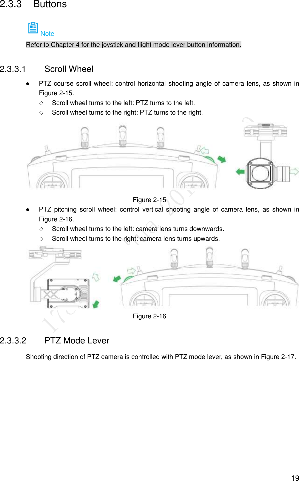
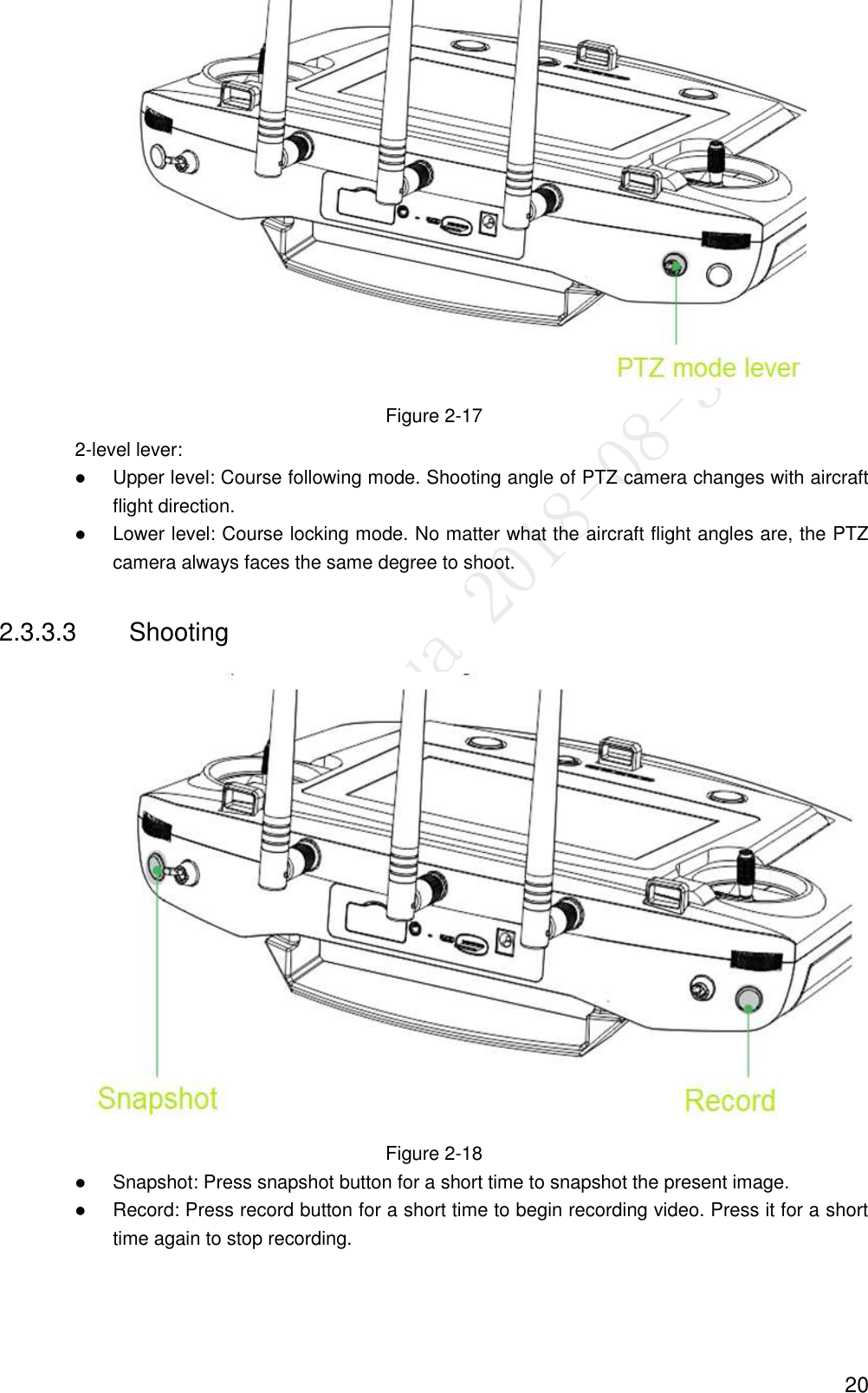
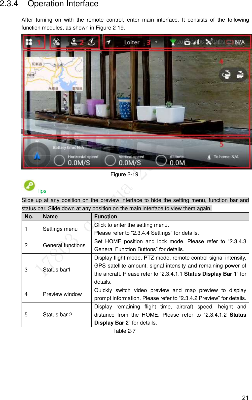
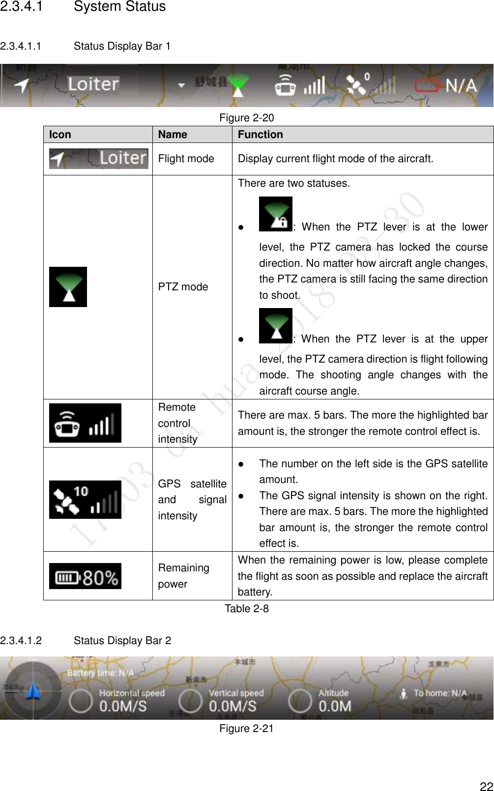
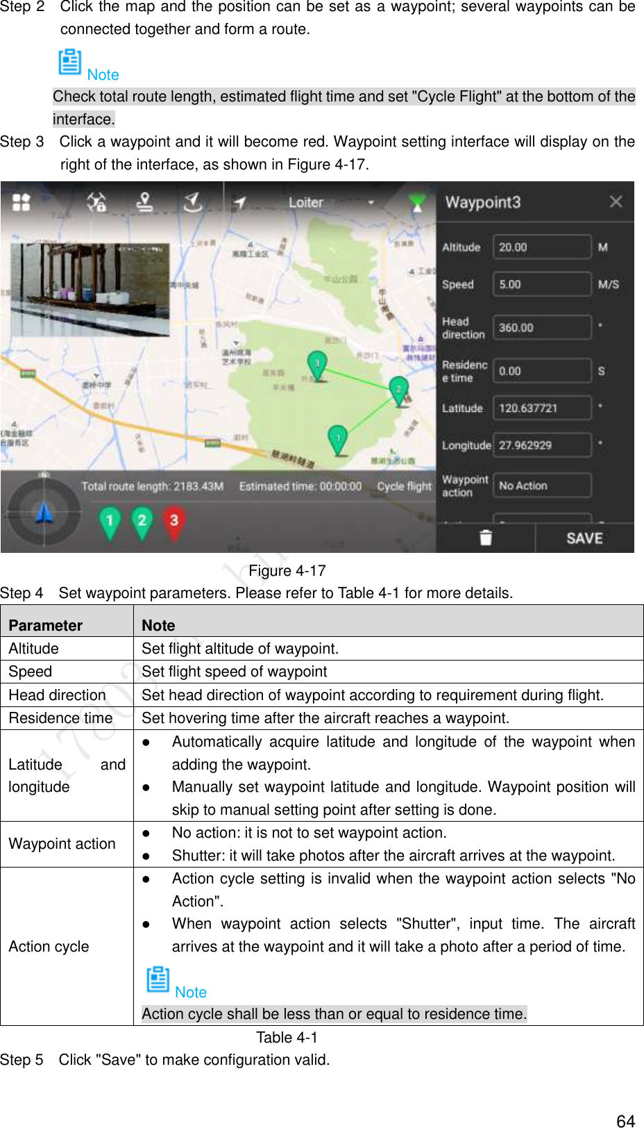
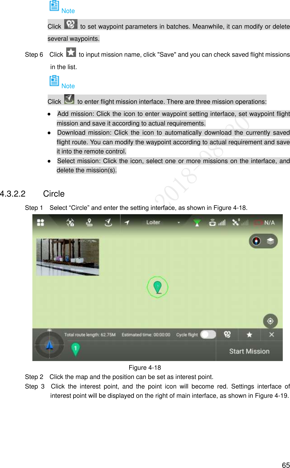
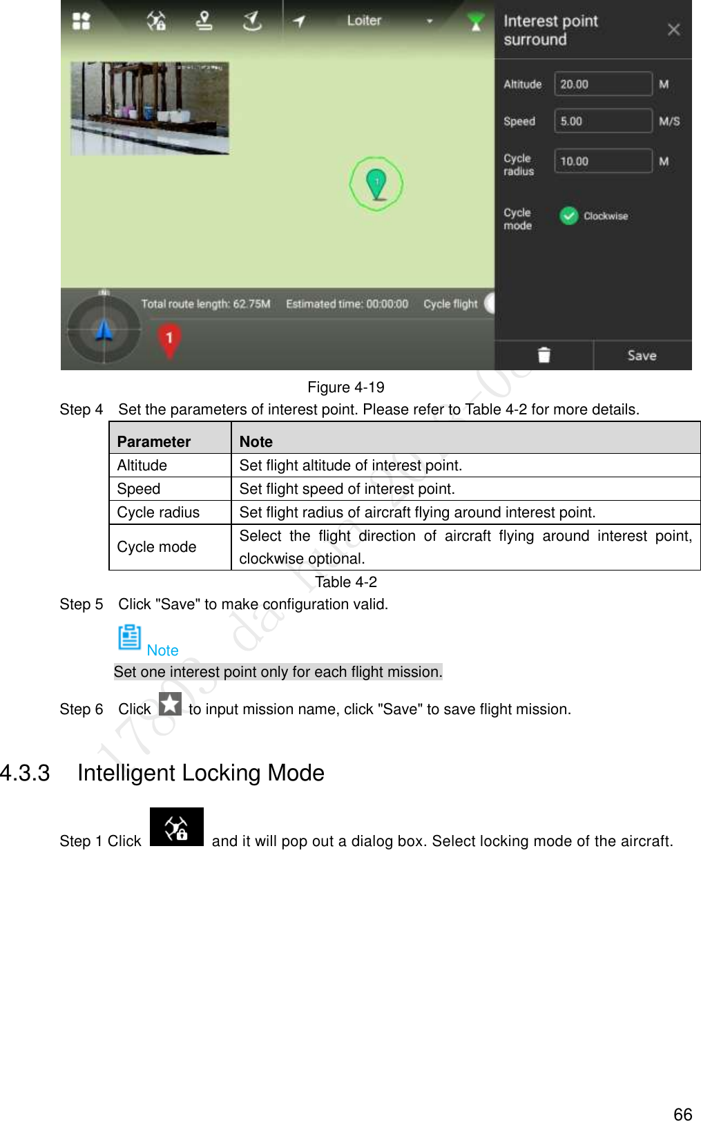
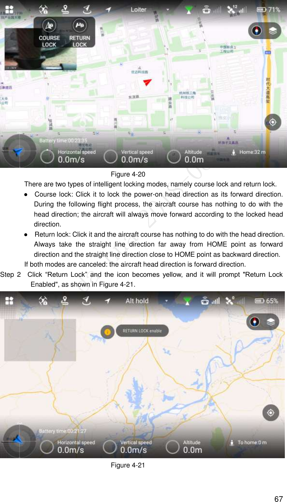
Zhejiang Dahua Vision Technology UAV-R1 UAV Remote Controller User Manual Navigator X1550 Users Manual
Zhejiang Dahua Vision Technology Co., Ltd UAV Remote Controller Navigator X1550 Users Manual
UserManual.wiki
>
Zhejiang Dahua Vision Technology
>
UAV R1 User Manual
Navigator X1550_Users Manual
Navigation menu
Upload a User Manual
Namespaces
Wiki Guide
HTML
PDF
Info
Views
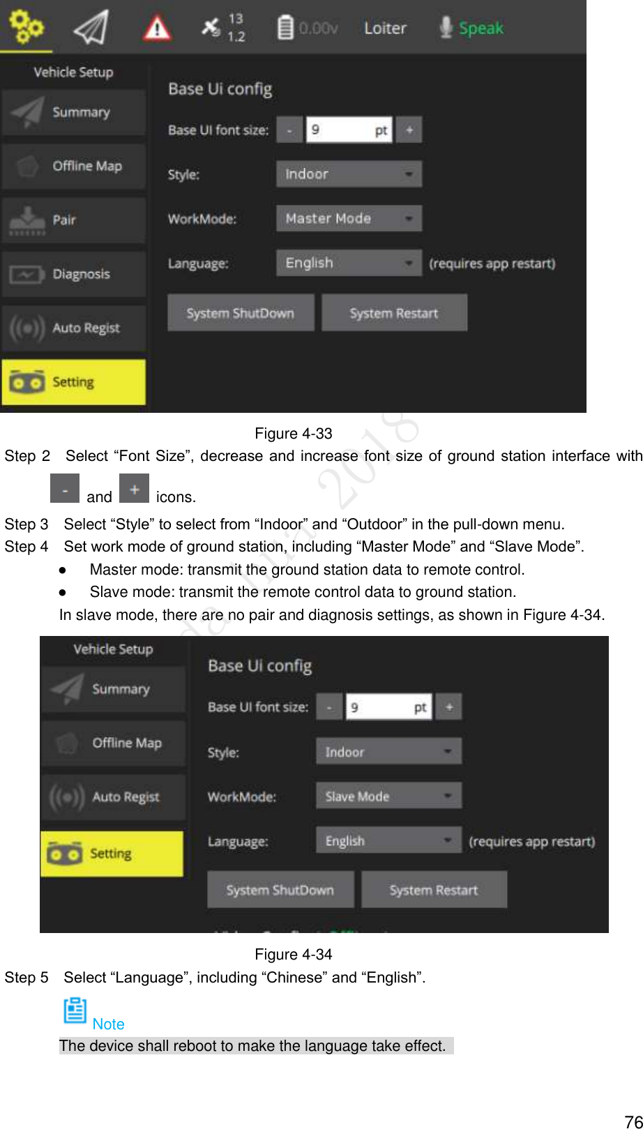
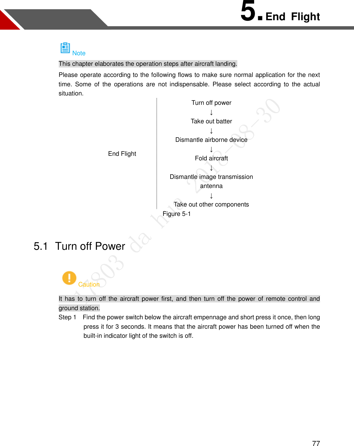
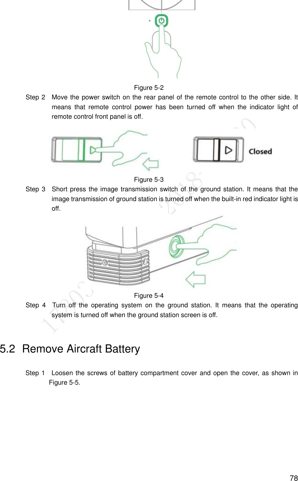
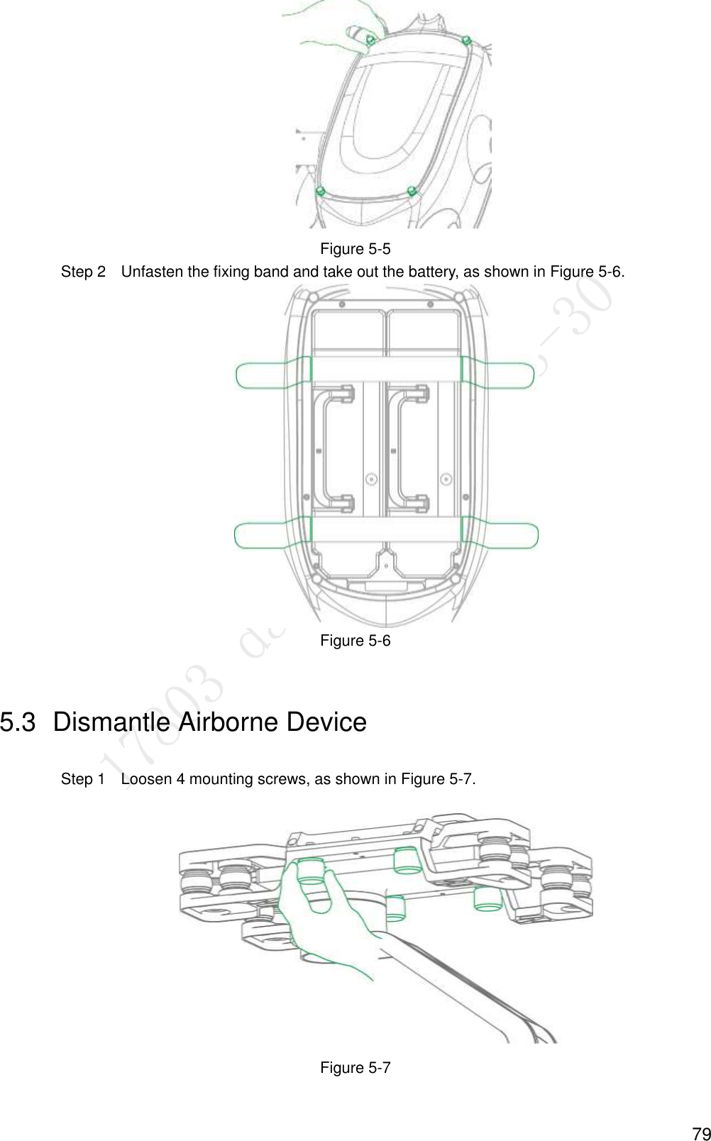
User Manual
Discussion / Help
Navigation