Zhejiang Dahua Vision Technology X650 NAVIGATOR X650 User Manual
Zhejiang Dahua Vision Technology Co., Ltd NAVIGATOR X650
UserManual.wiki
>
Zhejiang Dahua Vision Technology
>
X650 User Manual
User Manual
Navigation menu
Upload a User Manual
Namespaces
Wiki Guide
HTML
PDF
Info
Views
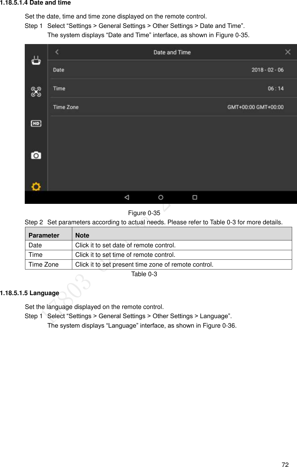
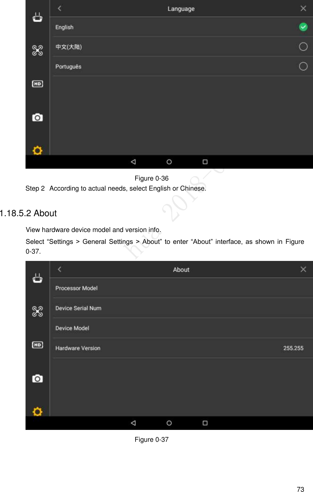
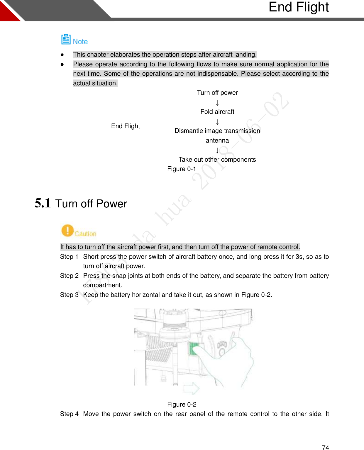
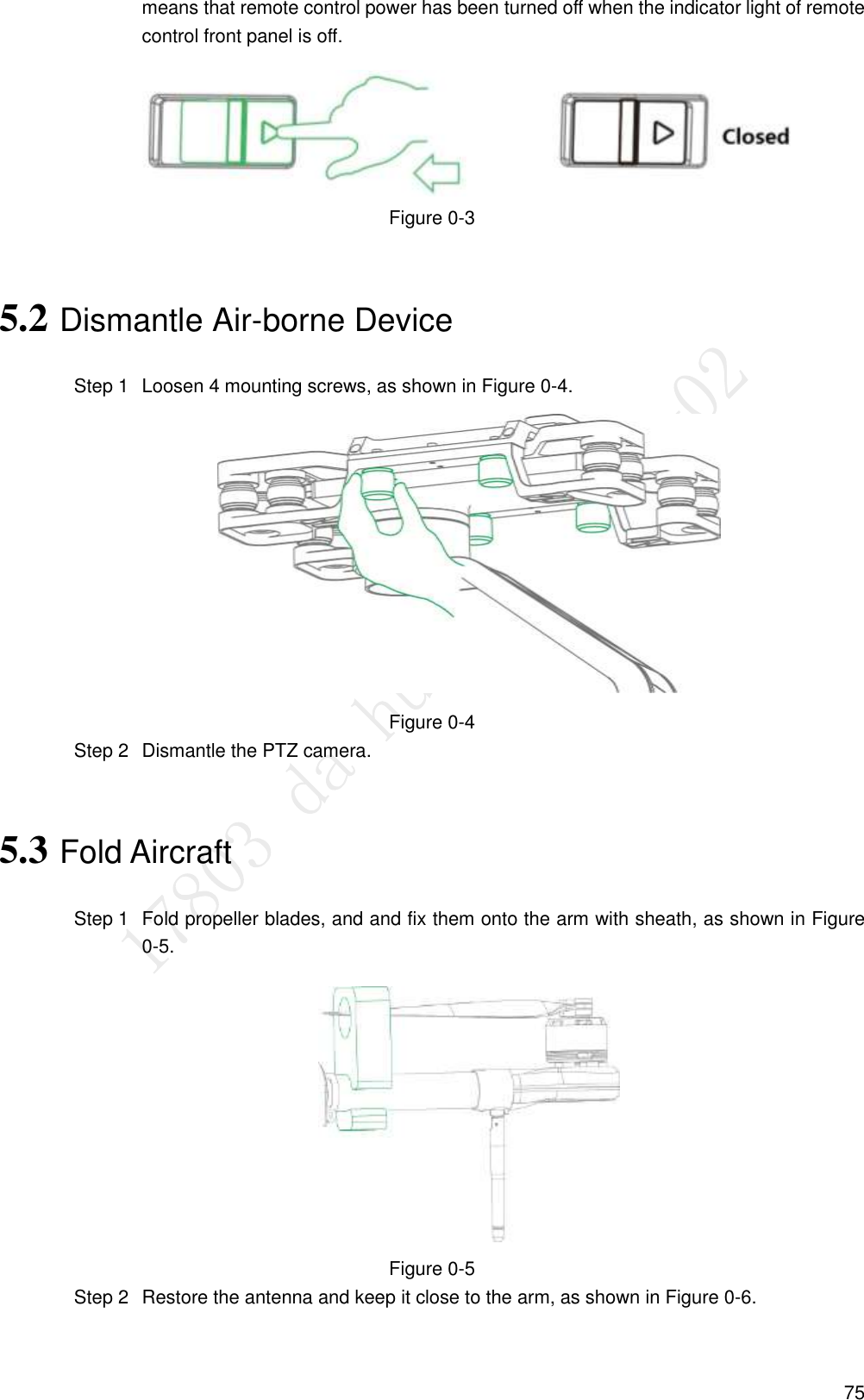
User Manual
Discussion / Help
Navigation