Zhejiang Flashforge 3D Technology CREATOR3 3D Printer User Manual
Zhejiang Flashforge 3D Technology CO., Ltd. 3D Printer
UserManual.wiki
>
Zhejiang Flashforge 3D Technology
>
CREATOR3 User Manual
User Manual
Navigation menu
Upload a User Manual
Namespaces
Wiki Guide
HTML
PDF
Info
Views
User Manual
Discussion / Help
Navigation
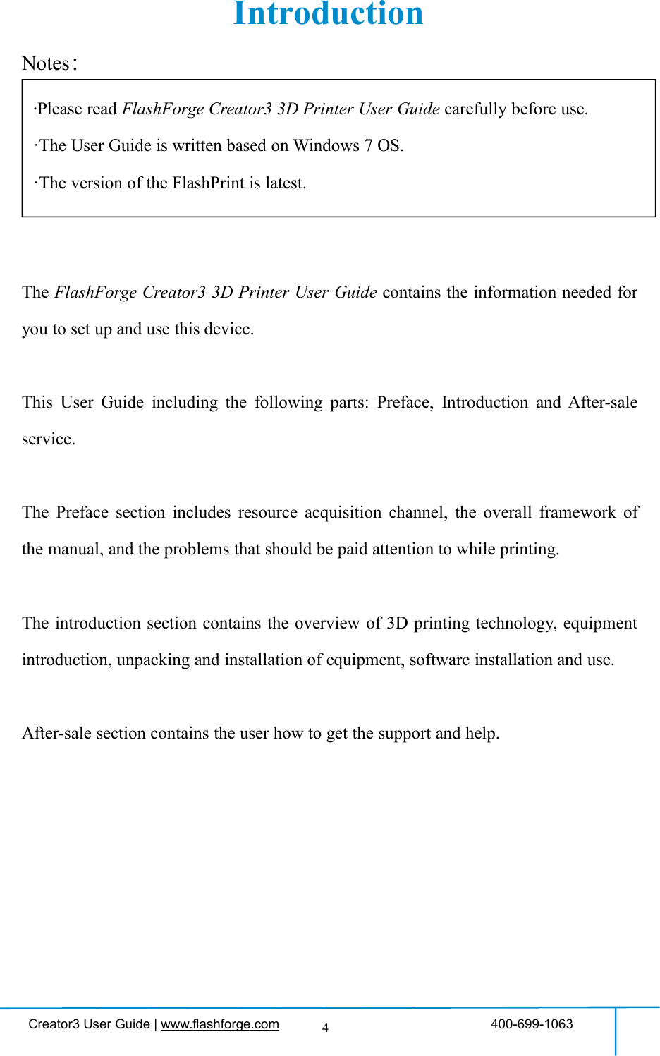

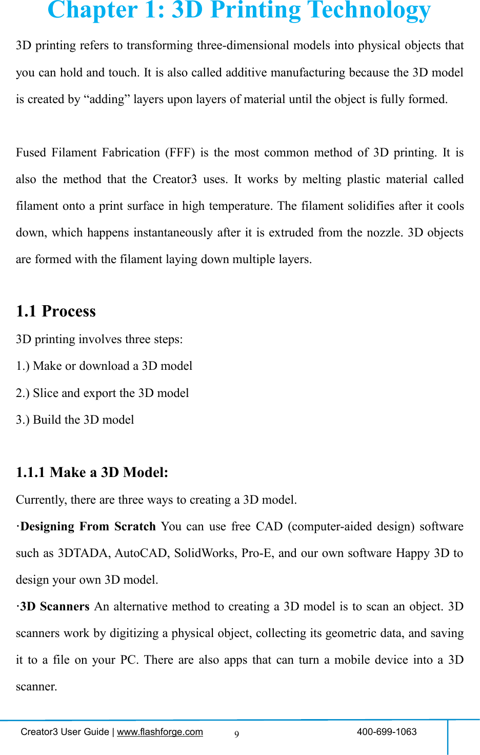
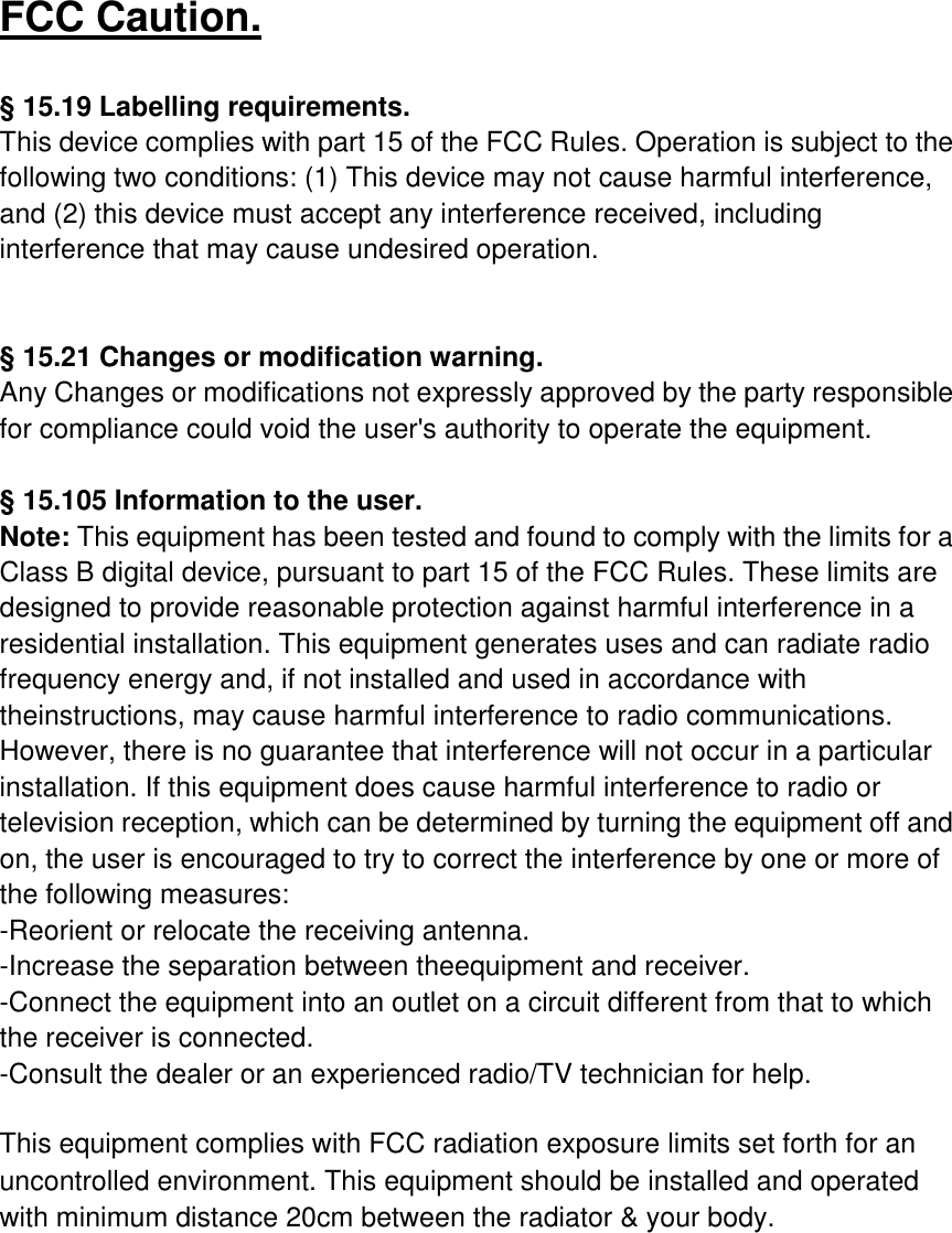
![Creator3 User Guide | www.flashforge.com 400-699-106316To set Extruder/Platform temperature duringprinting:After temperature has reached targettemperature, temperature figure will beunderlined in print interface,Tap [Yes] to save the setting while tap [No]to cancel the setting.Tools in print interfaceFilament: To change filament duringprinting. (Note: You need to suspendprinting first.)Light off:To turn off the light during printing.Details: To check the details interfaceduring printing.Details Interfacea.Printing speed: To change printing speedduring printing by tapping the underlinedspeed figure.b.Filament usedc.Time neededd. Z axis positionTo set the printing speed during printing:Tap [Yes] to save the setting while tap [No]to cancel the setting.123abcde](https://usermanual.wiki/Zhejiang-Flashforge-3D-Technology/CREATOR3/User-Guide-4089072-Page-16.png)
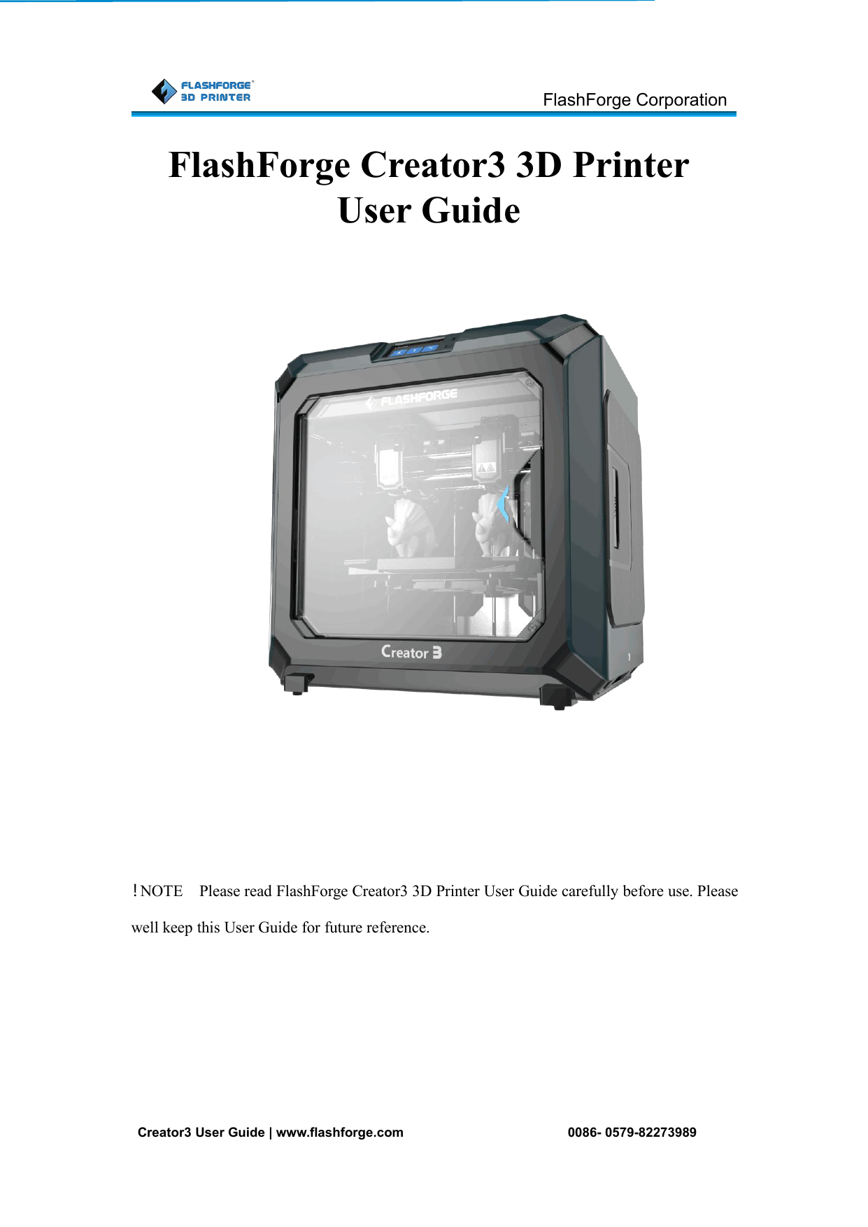
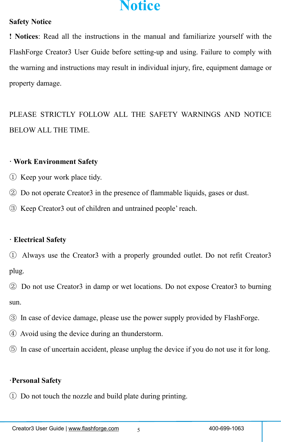
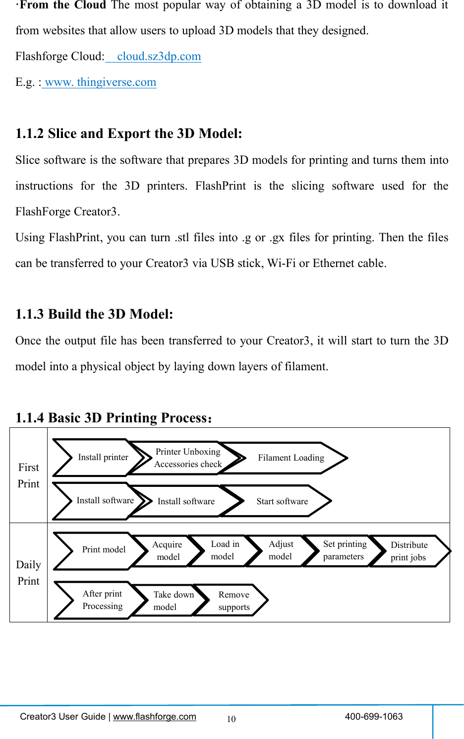
![Creator3 User Guide | www.flashforge.com 400-699-106317ToolsTap [Tools] to enter the tools interface .PreheatTap the [Preheat] button to enter thepreheat interface. Tap the [Start] button toheat up to the target temperature.The default temperature is Extruder 220℃and Platform 100℃.Tap the temperature display bar to set thetemperature.](https://usermanual.wiki/Zhejiang-Flashforge-3D-Technology/CREATOR3/User-Guide-4089072-Page-17.png)
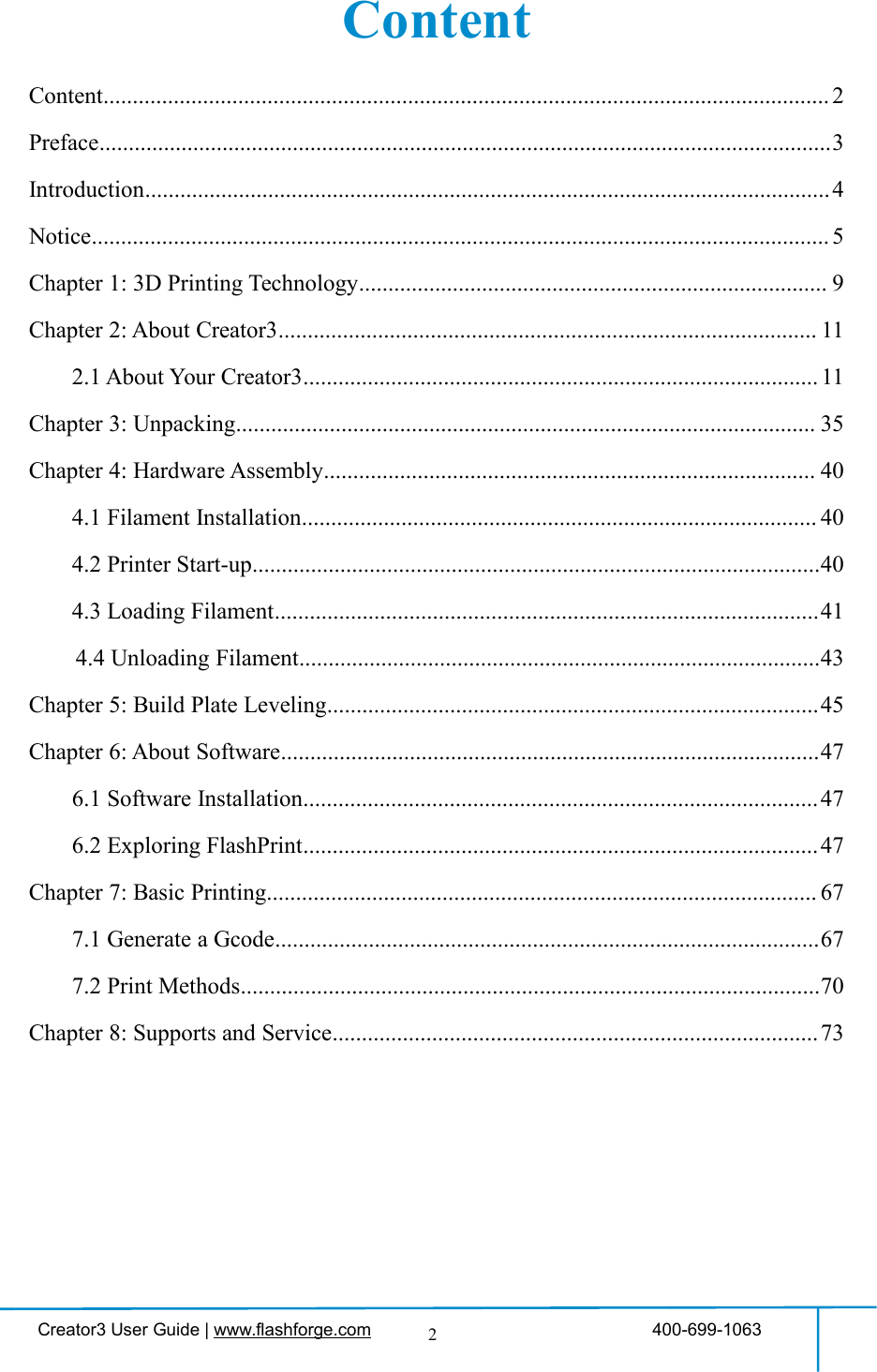
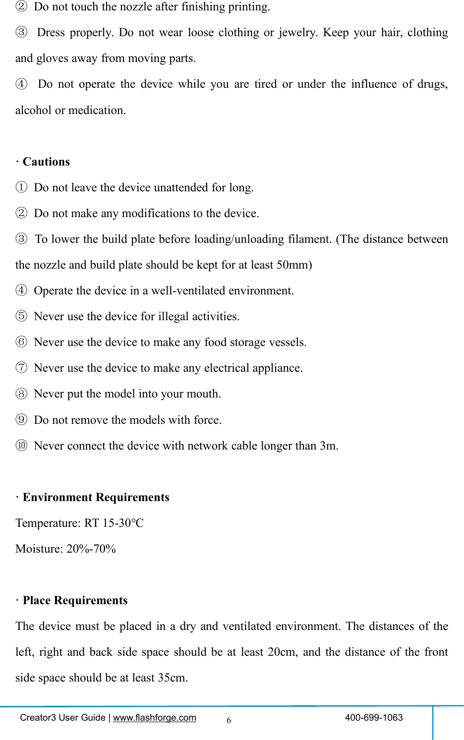
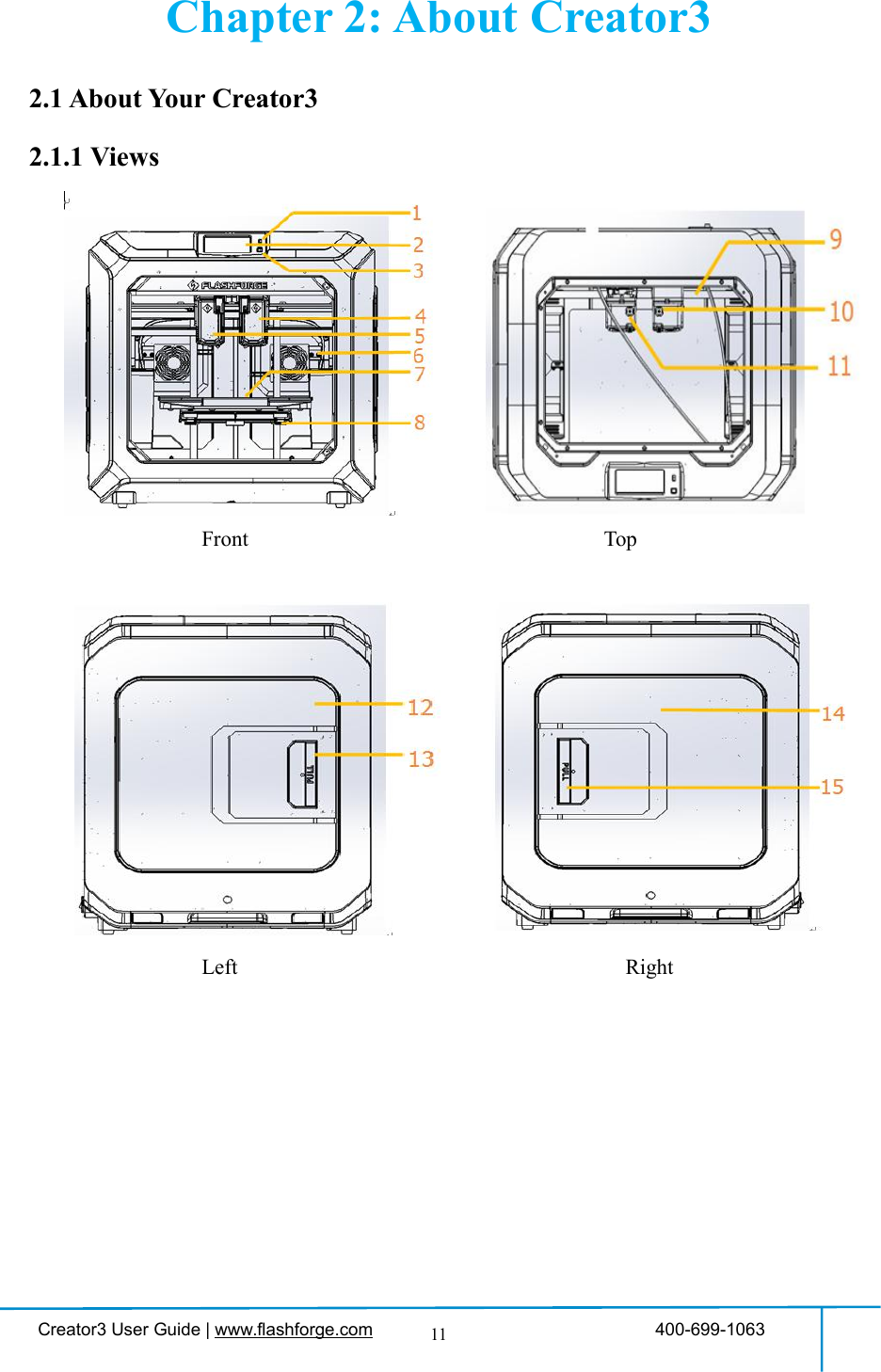
![Creator3 User Guide | www.flashforge.com 400-699-106318ToolsTap [Tools] to enter tool options.1.Filament: To load/unload the filament.2.Level: To adjust the build plate.3.Home: To make the X, Y and Z axes back to thezero point.4.Manual: To manually adjust the positions of X, Yand Z axes.5.Setting: To implement relevant function setups.6.Status: To check the real-time status of theprinter.7.About: Information about the printer.8.BackFilament Interface1.Load;2.Unload;3.Load-Left Extruder;4.Load-Right Extruder;5.Unload-Left Extruder;6.Unload-Right Extruder;7.Begin:Tap [Begin] to start load/unload filamenton Left/Right extruder.8.Back.1234657812345678](https://usermanual.wiki/Zhejiang-Flashforge-3D-Technology/CREATOR3/User-Guide-4089072-Page-18.png)
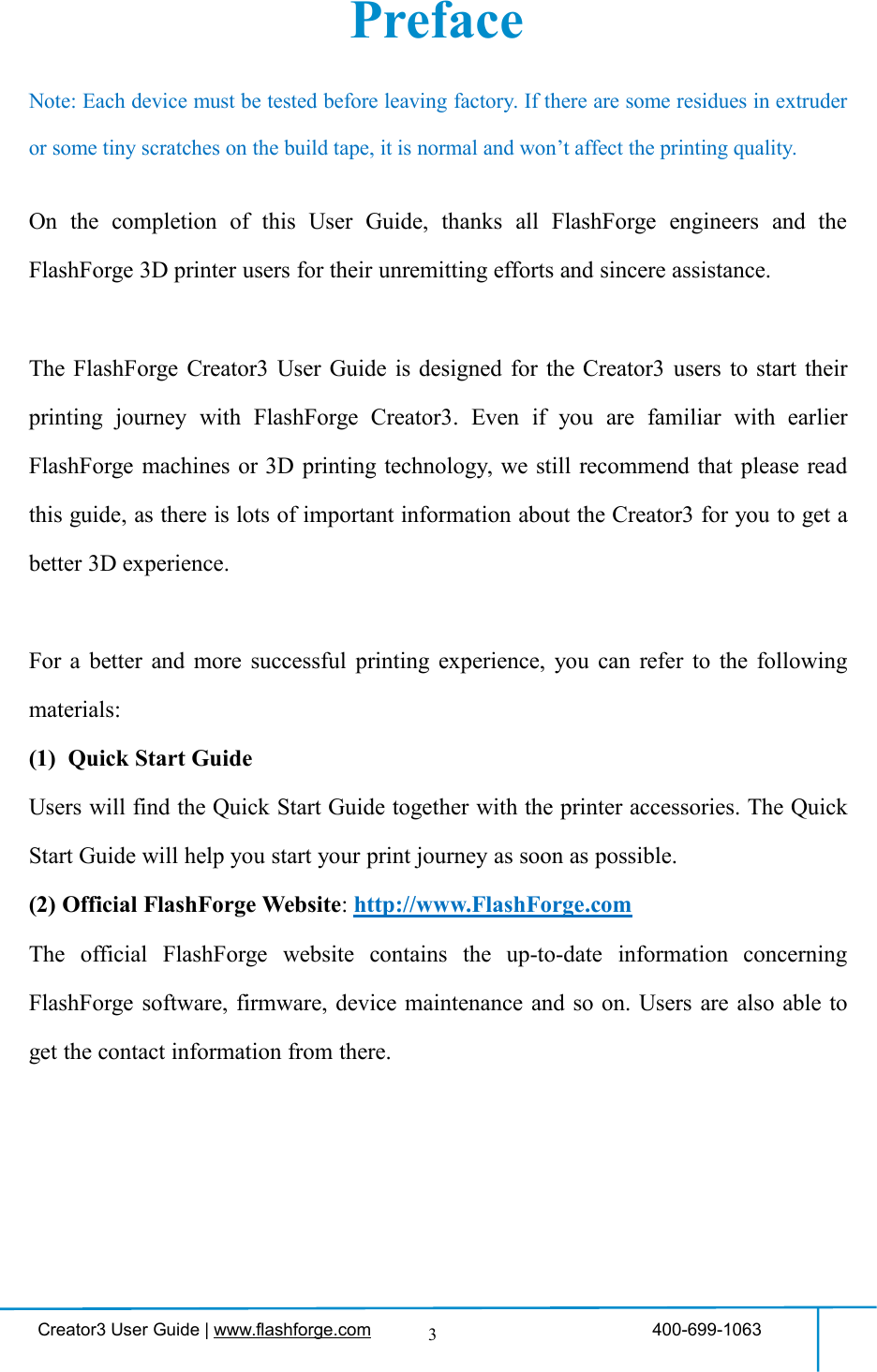
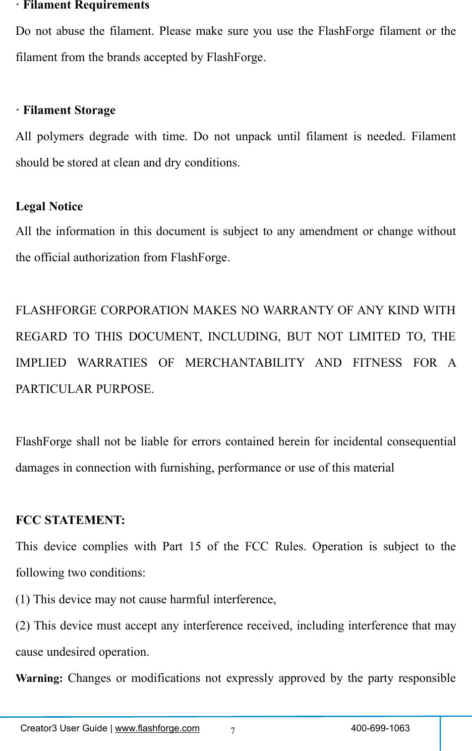
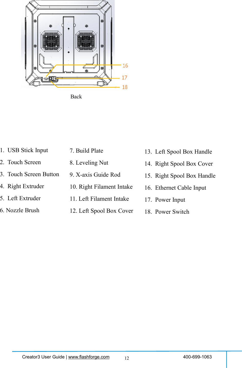
![Creator3 User Guide | www.flashforge.com 400-699-106319Filament Preheata. Left extruder preheat progress;b. Right extruder preheat progress;c. Actual temperature/target temperature;d. Actual temperature/target temperature;e. Cancel:Tap [Cancel] button to abort preheat job.f. Back.g. Done:Operate according to the instruction onthe touch screen,tap [Done] to finish filament load.h. Done:Operate according to the instruction onthe touch screen,tap [Done] to finish filamentunload.abcdfegh](https://usermanual.wiki/Zhejiang-Flashforge-3D-Technology/CREATOR3/User-Guide-4089072-Page-19.png)
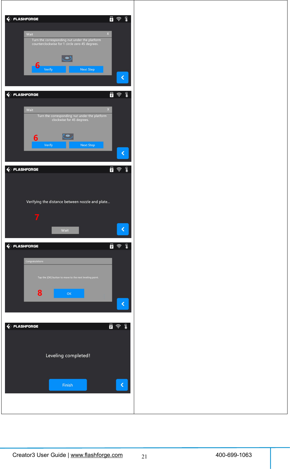
![Creator3 User Guide | www.flashforge.com 400-699-106320Level:1. Tap [Level] to start leveling.2. Wait while the extruder and platform finishhoming movements.3. Tap to choose extruder adjust level:Use Left or Right extruder to do the leveling.4. Wait while the extruder and platform finishinitial movements. Extruder move to the firstpoint to do the leveling.5. Wait for the extruder verifying distancebetween nozzle and plate.6. Operate according to the instruction on thetouch screen, then tap [Verify].7. Wait for the extruder verifying distancebetween nozzle and plate in the first point.8. If the distance in the first point is appropriate,tap [OK] to move to the next point to do theleveling.If the distance in the first point is not appropriate,operate according to the instruction on the touchscreen, then tap [Verify] again.Repeat the steps 5 to 8 to do the next two pointsleveling until you see [Finish].Tap [Finish] to complete leveling.Note: By tapping [Next Step],you can skipthe point’s leveling, this will affect levelingresult or printing effect.35124](https://usermanual.wiki/Zhejiang-Flashforge-3D-Technology/CREATOR3/User-Guide-4089072-Page-20.png)
![Creator3 User Guide | www.flashforge.com 400-699-106322Home:To make the X, Y and Z axes back to the zeropoint.1.Home: Tap[Home] to do the homing.2.Wait for the extruder do the homing.3.Homing is completed, tap[Yes].Manual:To manually adjust the positions of X, Y and Zaxes.Tap[Manual] to do the manual adjustment.Y+: The extruder moves to the zero point, thatis, the back of the machine.Y-: The extruder moves to the direction oppositeto the Y+.X+: The extruder moves to the zero points, thatis, to the right direction.X-: The extruder moves to the direction oppositeto the X+.Z+: The build plate descends.Z-: The build plate elevates.Back1312](https://usermanual.wiki/Zhejiang-Flashforge-3D-Technology/CREATOR3/User-Guide-4089072-Page-22.png)
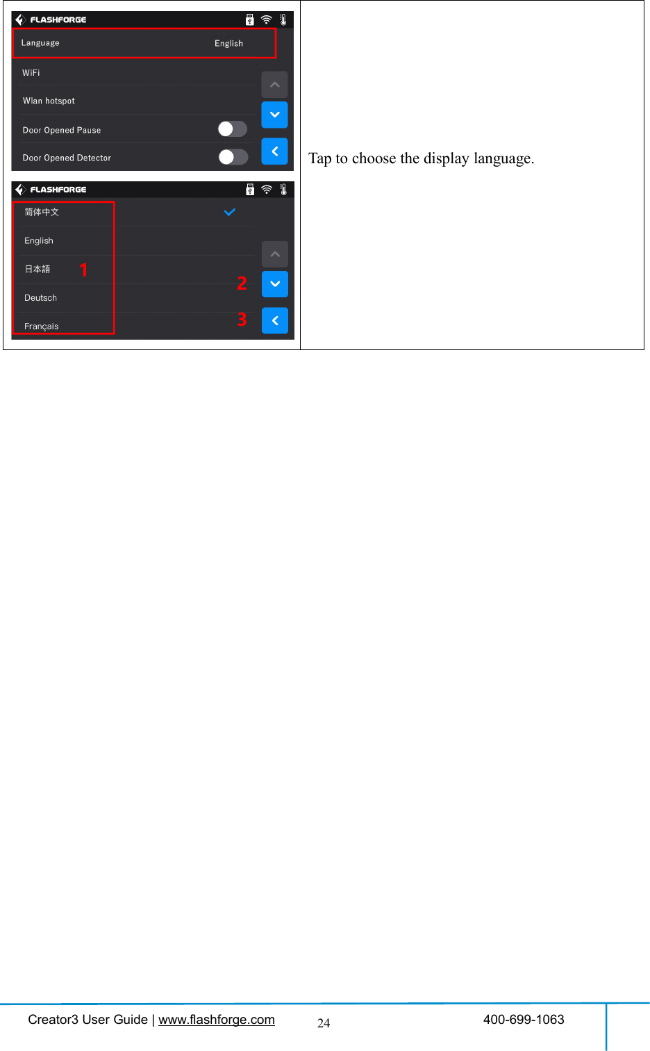
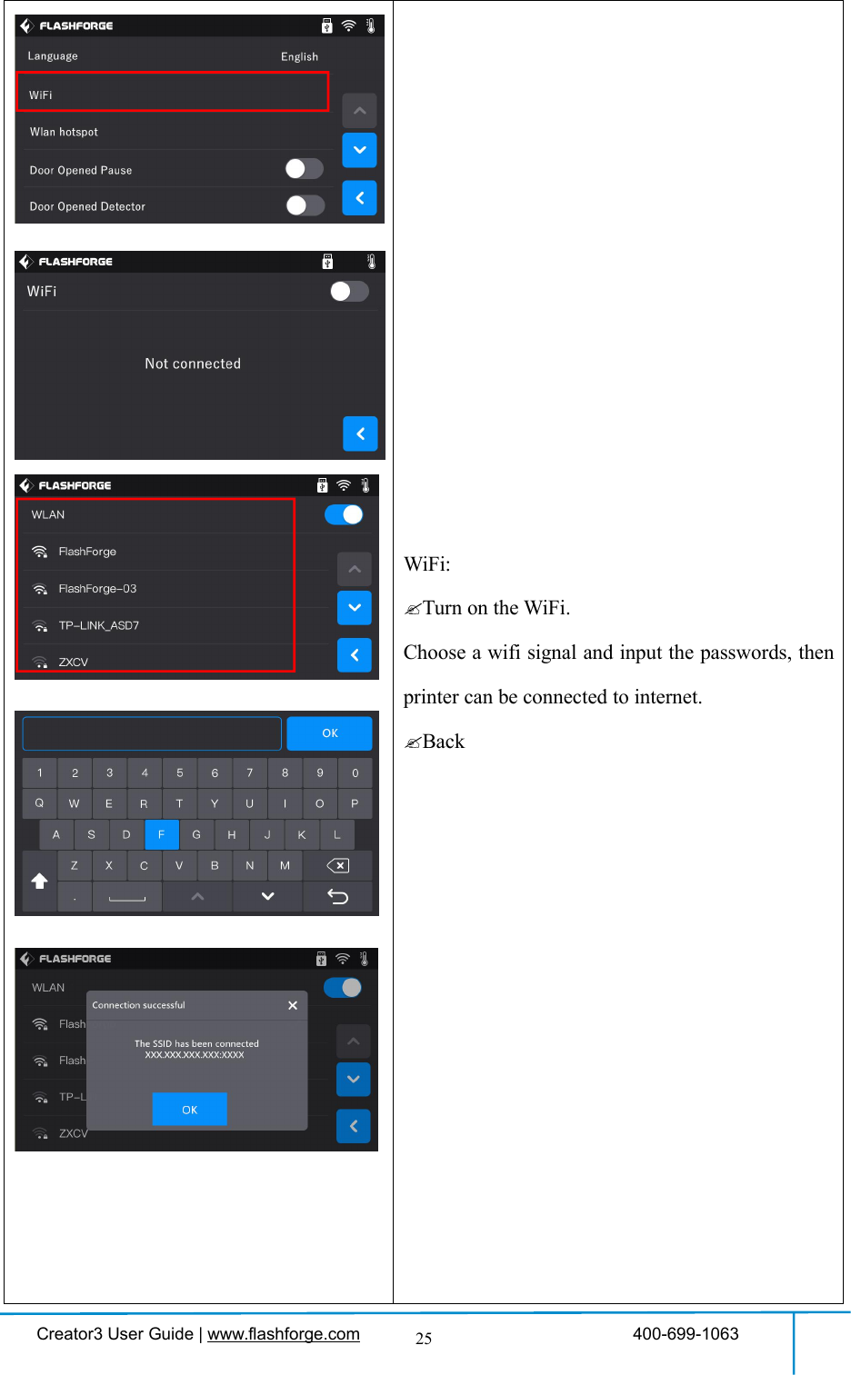
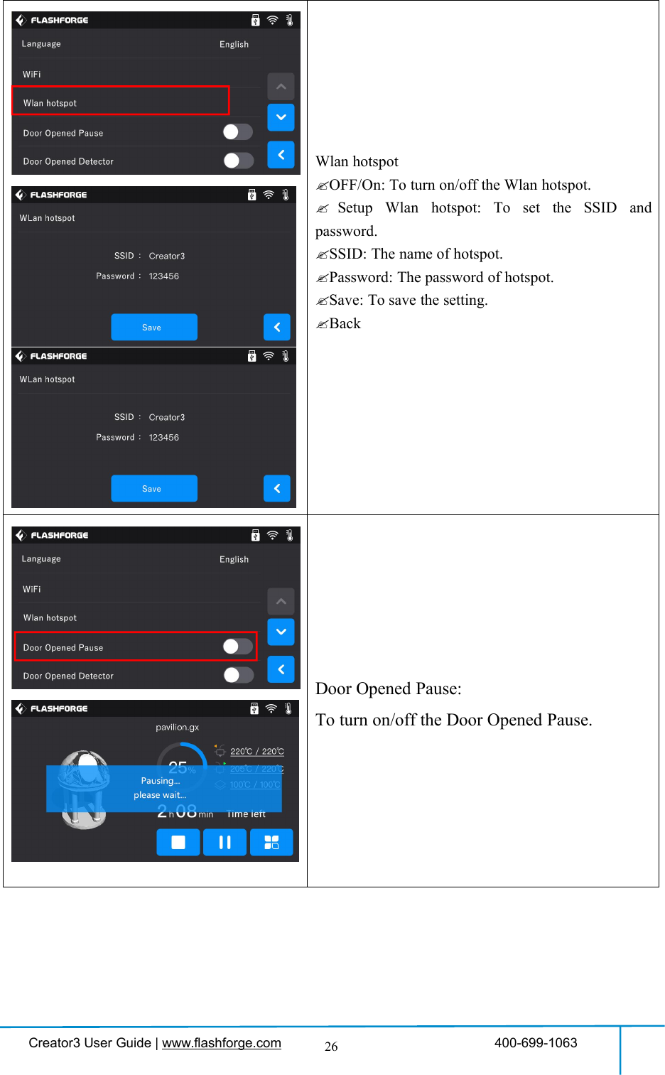
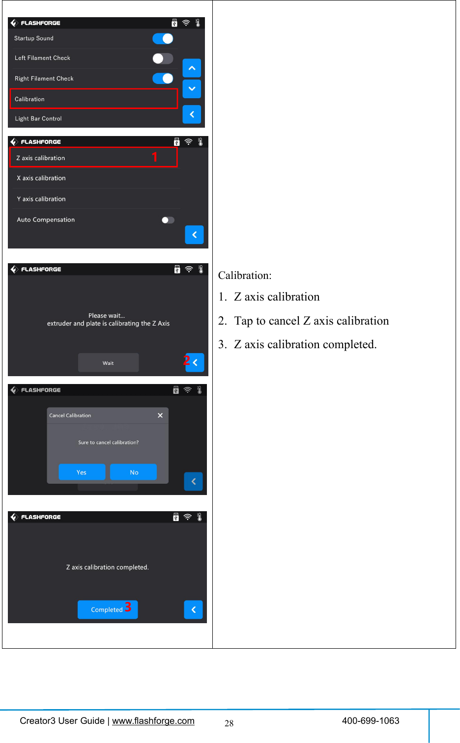
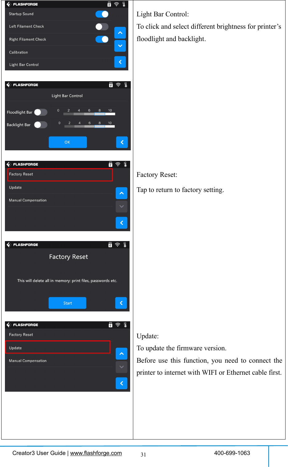
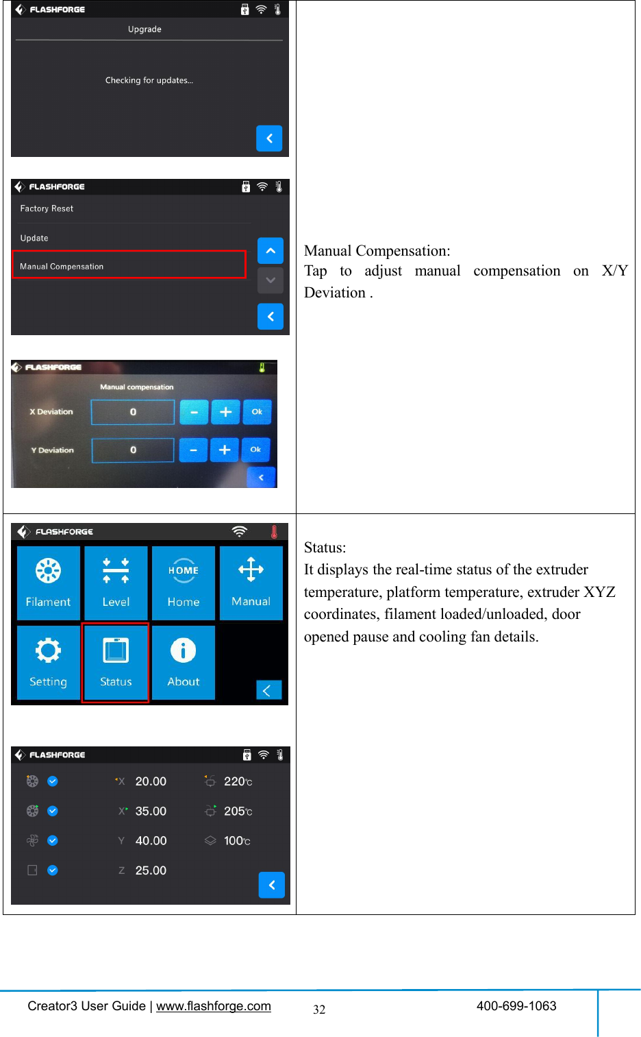
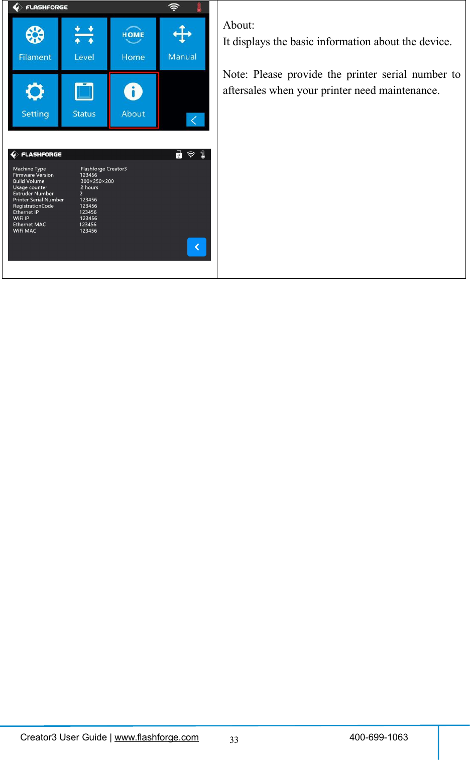
![Creator3 User Guide | www.flashforge.com 400-699-106323SettingTo implement relevant function setups.Tap [Setting] to enter the setting interface:1. Language: To set the display language2. WiFi: To turn on/off the WiFi3. WLan hotspot: To turn on/off the WLanhotspot.4. Door Opened Pause:To turn on/off the DoorOpened Pause.5. Door Opened Detector:To turn on/off the DoorOpened Detector.6. Startup Sound: To turn on/off the StartupSound.7. Left Filament Check: To turn on/off thefilament check on left extruder.8. Right Filament Check: To turn on/off thefilament check on right extruder.9. Calibration: To adjust the initial distancebetween the extruder and the build plate.10. Light Bar Control: To turn on/off the light barcontrol.11. Factory Reset: Return to factory setting.12. Update: To update the firmware version.13. Manual Compensation: To set the X/Ydeviation.12345678910111213](https://usermanual.wiki/Zhejiang-Flashforge-3D-Technology/CREATOR3/User-Guide-4089072-Page-23.png)
![Creator3 User Guide | www.flashforge.com 400-699-106327Door Opened Detector:To turn on/off the Door Opened Detector.After this function is turned on, Door openednote will pop out when door is opened duringprinting. After tapping[OK], note will pop outevery 5 minutes.Turn on/off [Startup Sound]:Tap to turn on/off the sound when restart the printer.Turn on[Left/Right Filament Check]:After [Filament Check] is turned on, Filamentabnormal status will be detected when filament isused up or suspended.Turn off [Left/Right Filament Check]:After [Filament Check] is turned off, Filamentabnormal status won’t be detected when filament isused up or suspended.[Filament Check] function should be used withfilament in the filament cartridge.This function isinvalid if using filament out of the cartridge.](https://usermanual.wiki/Zhejiang-Flashforge-3D-Technology/CREATOR3/User-Guide-4089072-Page-27.png)
![Creator3 User Guide | www.flashforge.com 400-699-106329Calibration1. X axis calibration: Tap[X axis calibration];2. Extruder begins to do the calibration:Left extruder begins to print baseline, after leftextruder finished printing 40baseline, leftextruder will move to the outside of buildplate.3. Tap to choose the first line printed by rightextruder is located on left or right of leftextruder printing basic line.4. Choose a group of most fitable basic lines,tap[Yes].5. X axis calibration completed.Tap[Completed] to finish.12345](https://usermanual.wiki/Zhejiang-Flashforge-3D-Technology/CREATOR3/User-Guide-4089072-Page-29.png)
![Creator3 User Guide | www.flashforge.com 400-699-106330Calibration1. Y axis calibration: Tap[Y axis calibration];2. Extruder begins to do the calibration:Left extruder begins to print baseline, after leftextruder finished printing 30baseline, leftextruder will move to the outside of buildplate.3. Tap to choose the first line printed by rightextruder is located on front or rear of leftextruder printing basic line.4. Choose a group of most fitable basic lines,tap[Yes].5. Y axis calibration completed.Tap[Completed] to finish.12345](https://usermanual.wiki/Zhejiang-Flashforge-3D-Technology/CREATOR3/User-Guide-4089072-Page-30.png)
![Creator3 User Guide | www.flashforge.com 400-699-106338(3-8)Remove the buckles which are used to fasten extruders and rods, move the twoextruders left to right and front to rear, to check extruders and rods all right.3-9(3-9)Take out power cable and plug the power cable into the input on the back andturn on the power switch. Press the touch screen button and tap [Tools].3-10(3-10)Tap [Manual], then Tap [Z-] to partially elevate the build plate.](https://usermanual.wiki/Zhejiang-Flashforge-3D-Technology/CREATOR3/User-Guide-4089072-Page-38.png)
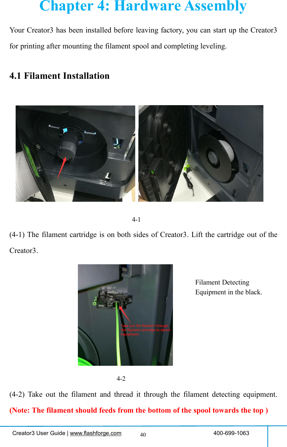
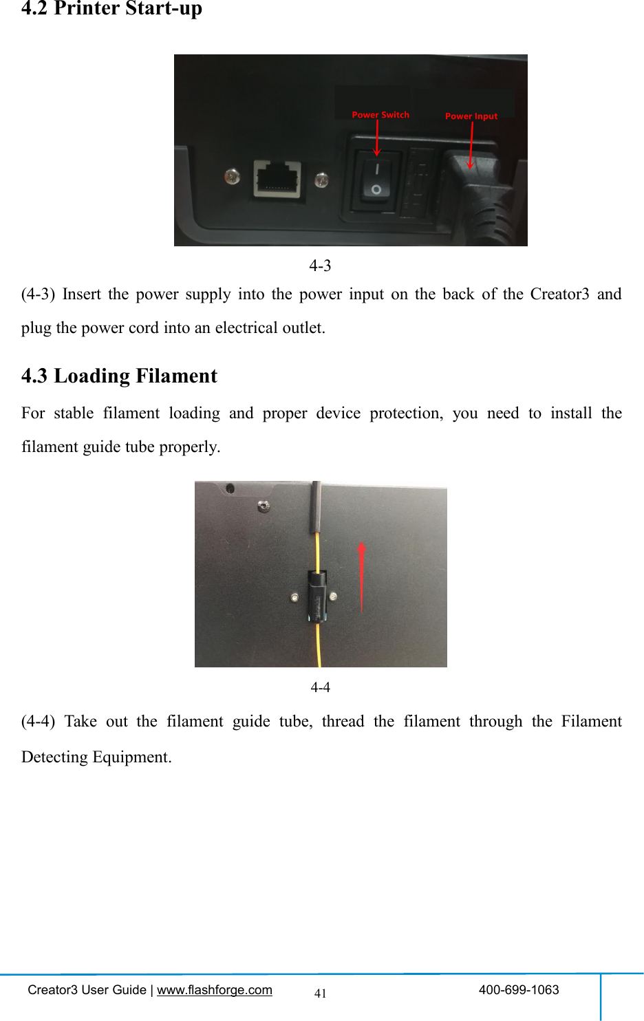
![Creator3 User Guide | www.flashforge.com 400-699-106342(4-6) Insert the filament from the filament guide tube into the filament intake.Next, we will load the FlashForge filament. (Note: Please lower the build plate toincrease the distance between the nozzle and build plate to 50mm at least foravoiding nozzle jam.)(4-7) Tap [Tools].图4-64-84-74-6](https://usermanual.wiki/Zhejiang-Flashforge-3D-Technology/CREATOR3/User-Guide-4089072-Page-42.png)
![Creator3 User Guide | www.flashforge.com 400-699-106343(4-8) Tap [Filament]--[Load]4-9(4-9)After the extruder’s temperature reaches 220℃, the printer will sound a beep toprompt you to load the filament into the extruder.4-10(4-10)Insert the filament into the extruder at an upright angle. Then the filament willbe drawn through the extruder. Do not tap [Cancel] until the filament load the extrudersteadily.4.4 Unloading Filament4-11](https://usermanual.wiki/Zhejiang-Flashforge-3D-Technology/CREATOR3/User-Guide-4089072-Page-43.png)
![Creator3 User Guide | www.flashforge.com 400-699-106344(4-11) Tap [Tools]-[Unload] and the extruder starts heating up.4-12(4-12) After the extruder reaches 220℃, the printer will sound a beep to prompt you tounload the filament from the extruder. Press the spring presser, press down thefilament for about three seconds and gently pull the filament out.Note: Do not pull out the filament with force as it will damage the gears. If themelted filament has cooled down in the extruder, please repeat the steps above.](https://usermanual.wiki/Zhejiang-Flashforge-3D-Technology/CREATOR3/User-Guide-4089072-Page-44.png)
![Creator3 User Guide | www.flashforge.com 400-699-106345Chapter 5: Build Plate LevelingCreator3 creatively adopts a three-point intelligent leveling system, which will giveclear and comprehensive feedback to users. There are three spring-loaded nuts underthe build platform. The distance between the plate and nozzle increases whiletightening the nuts. On the contrary, the distance reduces.(5-1) Tap [Level] to start leveling. Wait while the extruder and platform finish homingmovements.(5-2) Tap to choose extruder adjust level: Use Left or Right extruder to do the leveling.(5-3) Wait while the extruder and platform finish initial movements, Extruder move tothe first point to do the leveling. Wait for the extruder verifying distance betweennozzle and plate.](https://usermanual.wiki/Zhejiang-Flashforge-3D-Technology/CREATOR3/User-Guide-4089072-Page-45.png)
![Creator3 User Guide | www.flashforge.com 400-699-106346(5-4) Operate according to the instruction on the touch screen, then tap [Verify].(5-5) Wait for the extruder verifying distance between nozzle and plate on the firstpoint. If the distance on the first point is appropriate, tap[OK] to move to the nextpoint to do the leveling. If the distance on the first point is not appropriate, operateaccording to the instruction on the touch screen, then tap [Verify] again.(5-6) Repeat the above steps to do the next two points leveling until you see [Finish].Tap [Finish] to complete leveling.Note: By tapping [Next Step] ,you can skip the point’s leveling, this will affectleveling result or printing effect.](https://usermanual.wiki/Zhejiang-Flashforge-3D-Technology/CREATOR3/User-Guide-4089072-Page-46.png)
![Creator3 User Guide | www.flashforge.com 400-699-106347Chapter 6: About Software6.1 Software Installation6.1.1 Software AcquisitionMethod 1: To get the installation package from the USB stick in the toolkit.Method 2: Open the link below to download the installation package:http://www.flashforge.com/support-center/flashprint-support/Steps:Support---Downloads---FlashPrint---Choose the software version ---Download6.1.2 Software Installation and Start-up1. Decompress the zipped file or start the installation program, and then install thesoftware according to the direction.2. Start the software with the start menu shortcut or by clicking the software icon.6-16.2 Exploring FlashPrint6.2.1 Machine Type Selection! After starting FlashPrint, you need to select the target machine type first.When you start FlashPrint, a dialog box will pop up. Just select FlashForge Creator3 inthe machine type list and click [OK]. You can also change the machine type viaclicking [Print]--[Machine type]. See graphic 6-2:](https://usermanual.wiki/Zhejiang-Flashforge-3D-Technology/CREATOR3/User-Guide-4089072-Page-47.png)
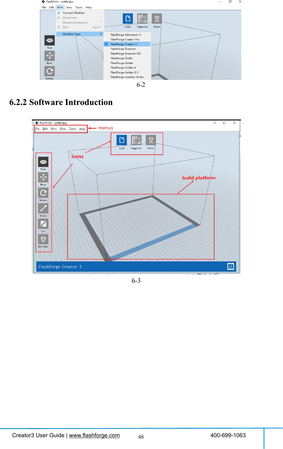
![Creator3 User Guide | www.flashforge.com 400-699-106349Load files.Enter the support edit modePrint it directly with your Creator3 or export to your USB StickView FlashPrint home screen from one of six viewing anglesMove model around on XY-plane; shift+click to move along Z axisTurn and rotate your modelScale the size of your objectCut model into several partsSet details of extruders6.2.3 LoadingYou can load a model file or Gcode file into your FlashPrint by the following sixmethods:Method 1: Click the [Load] icon on the main interface. Then select theobject file.Method 2: Select the file for loading and drag the file to the main interface of thesoftware.Method 3: Click [File]--[Load File]. Then select the object file for loading.Method 4: Click [File]--[Examples]to load the example files](https://usermanual.wiki/Zhejiang-Flashforge-3D-Technology/CREATOR3/User-Guide-4089072-Page-49.png)
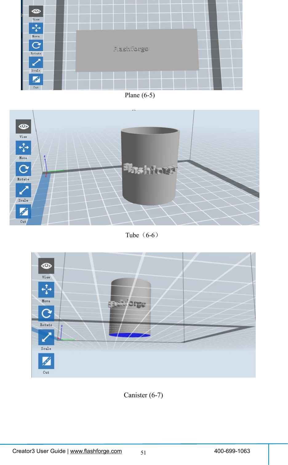
![Creator3 User Guide | www.flashforge.com 400-699-106350Method 5: Click [File]--[Recent Files]to load the files opened recently.Method 6: Select and drag the target file to the icon of FlashPrint.Note: .STL, .OBJ, and .FPP,ways to store 3D models, are supported by FlashPrintfor editing.Generating RilievoLoad a png, jpg, jpeg, bmp picture file into the FlashPrint. And the following dialoguebox (6-3) will pop up. The setting box includes settings for shape, mode, maximumthickness, base thickness, bottom thickness, width, height, top diameter and bottomdiameter.Shape: including plane, tube, canister and lamp.Mode: including “darker is higher” and “lighter is higher”.Maximum thickness: Z value of the modelBase thickness: The minimum raft thickness and the default value is 0.5mmWidth: X value of the modelDepth: Y value of the modelBottom thickness: For tube, canister and lamp to set up bottom thicknessTop diameter: For tube, canister lamp and seal to set up the top diameterBottom diameter: For tube, canister, lamp and seal to set up the bottom diameter6-4](https://usermanual.wiki/Zhejiang-Flashforge-3D-Technology/CREATOR3/User-Guide-4089072-Page-50.png)
![Creator3 User Guide | www.flashforge.com 400-699-106352Lamp (6-8)Seal (6-9)6.2.4 Views①Changing viewsChange model views by moving, rotating, scaling.●DragClick the [View] icon and then you can move the object by the following threemethods:Method 1: Hold down the left mouse button and drag.](https://usermanual.wiki/Zhejiang-Flashforge-3D-Technology/CREATOR3/User-Guide-4089072-Page-52.png)
![Creator3 User Guide | www.flashforge.com 400-699-106353Method 2: Hold down the mouse wheel and scroll up and down.Method 3: Hold down the Shift key, hold down the right mouse button and drag.●RotateClick the [View] icon and then you can rotate the object by the following twomethods:Method 1. Hold down the right mouse button and drag.Method 2. Hold down the Shift key, hold down the left mouse button and drag.●ScaleRotate the mouse wheel to enlarge or shrink the build plate.②Set ViewAllow users to view the object on the build plate. Six views are under the view menu,that is, bottom view, top view, front view, back view, left view and right view.Method 1: Click the the [View] button, there are six views in the drop- down listMethod 2: Click the the [Look] icon on the left, click it again and a submenuwill appear with six views for selecting.③Reset ViewAllow users to reset views by the following two methods:Method 1: Click the [View] menu and select [Home View]Method 2: Click the [View]button on the left, click it again and you will see theviewing options, you can click [Reset].④Show Model OutlineClick [View]--[Show Model Outline], it will highlight the yellow border of the object](https://usermanual.wiki/Zhejiang-Flashforge-3D-Technology/CREATOR3/User-Guide-4089072-Page-53.png)
![Creator3 User Guide | www.flashforge.com 400-699-106354⑤Show Steep OverhangClick [View]--[Show Steep Overhang]. When the intersection angle between themodel surface and horizontal line is within the overhang threshold value, the surfacehas steep overhang and it becomes red in the software. Overhang threshold valuecould be set as needed. The default value is 45 degree.6.2.5 MoveSelect the object and move the object by the following two methods:Method 1: Click the [Move] icon on the left, hold down the left mouse button anddrag to adjust the location of the model in XY direction. Hold down the Shift key,hold down the left mouse button and drag to adjust the location of the model in Zdirection. The distance and the direction of the movement shall be displayed.Method 2: Click the [Move]button on the left and then enter the distance value. Click[Reset]to reset distance values.Note: Users shall click [Center] and [On Platform] after the location adjustment toensure the model(s) be within the build area and on the build platform. If a specifiedposition is needed, only click [On Platform].6.2.6 RotateSelect the target object and rotate the object by the following two methods:Method 1: Click the [Rotate] icon on the left and three mutually perpendicular ringsappear around the object Click one ring and rotate on the present axis, you will see therotation angle and direction in the center of circle. In this way, you could make themodel rotate on X/Y/Z axis.Method 2: Click the [Rotate] icon on the left, and then enter into rotating angelvalues in X/Y/Z axes positioning. Click [Reset] to reset rotating angel values.](https://usermanual.wiki/Zhejiang-Flashforge-3D-Technology/CREATOR3/User-Guide-4089072-Page-54.png)
![Creator3 User Guide | www.flashforge.com 400-699-1063556.2.7 ScaleSelect the target object and scale the object by the following two methods:Method 1: Click the [Scale] icon on the left, hold down the left mouse button andscale the model. The corresponding values will display near the object.Method 2: Click the [Scale] icon on the left and then enter into scale values in X/Y/Zaxes positioning. Click the [Maximum] button to get largest size possible for building.Click [Reset] to reset the size of model.Note: If the [Uniform Scaling] radio button is clicked, it will scale the model in equalproportion when changing value in any positioning of the model. Otherwise it willonly change the value of the corresponding positioning.6.2.8 CutLeft-click on the model to select it and double-click on the [Cut] icon to set the cutplane. The direction and position are available for setting.①Draw with Mouse②X Plane](https://usermanual.wiki/Zhejiang-Flashforge-3D-Technology/CREATOR3/User-Guide-4089072-Page-55.png)
![Creator3 User Guide | www.flashforge.com 400-699-106356③Y Plane④Z Plane6.2.9 SupportsAfter loading the model, click [Edit]--[Supports]or click the Supports icon directly,then you will enter the support edit mode (as shown in the picture below). Click [Back]to exit when you finish editing.6-10](https://usermanual.wiki/Zhejiang-Flashforge-3D-Technology/CREATOR3/User-Guide-4089072-Page-56.png)
![Creator3 User Guide | www.flashforge.com 400-699-106357①Support OptionsClick the Support Options, an option box will appear, supports options include“treelike” and “linear”, when choose “treelike”, click [OK], then it will generatetreelike structure; when choose “linear”, click [OK], then it will generate linearstructure; if it is a model with supports, when you choose one of the supports options,software will judge whether existing supports need to be deleted or not on the basis ofthe type of existing support, and will pop up the corresponding prompt to let you makethe choice.②Auto SupportsClick the [Auto Supports] button, the software will judge the position where supportsare needed and generate corresponding treelike or linear supports. If it is a model withsupports, the existing supports will be deleted and new supports will be generated.③Add SupportsSupports will be added once clicking the [Add]button. Move the cursor to theposition where supports needed, left-click to choose the starting point of supports, holddown the left mouse button and drag the mouse the supports preview will show up (ifsupport surface doesn’t need support or the support column angle is too large, will6-11](https://usermanual.wiki/Zhejiang-Flashforge-3D-Technology/CREATOR3/User-Guide-4089072-Page-57.png)
![Creator3 User Guide | www.flashforge.com 400-699-106358highlight the support review). Loosen the left mouse button, if support column doesn’tmeet with model, then support will be generated on origin and terminal point (thehighlighted preview support won’t generate support structure )④Clear SupportsClick [Clear Supports], all supports will be deleted. The operation can be repealedvia clicking [Undo]or pressing the shortcut key Ctrl+Z.⑤Delete SupportsSupports will be deleted once clicking the [Delete]button. Move the cursor to thesupports needed deleting, current supports and its subnode support will be highlighted,click the left mouse button to delete these highlighted support.6.2.10 Print6-12①Preview: Choose to enter preview interface or not②Print when slice done: Print or not when slice done③Material type: Choose according to the type of model](https://usermanual.wiki/Zhejiang-Flashforge-3D-Technology/CREATOR3/User-Guide-4089072-Page-58.png)
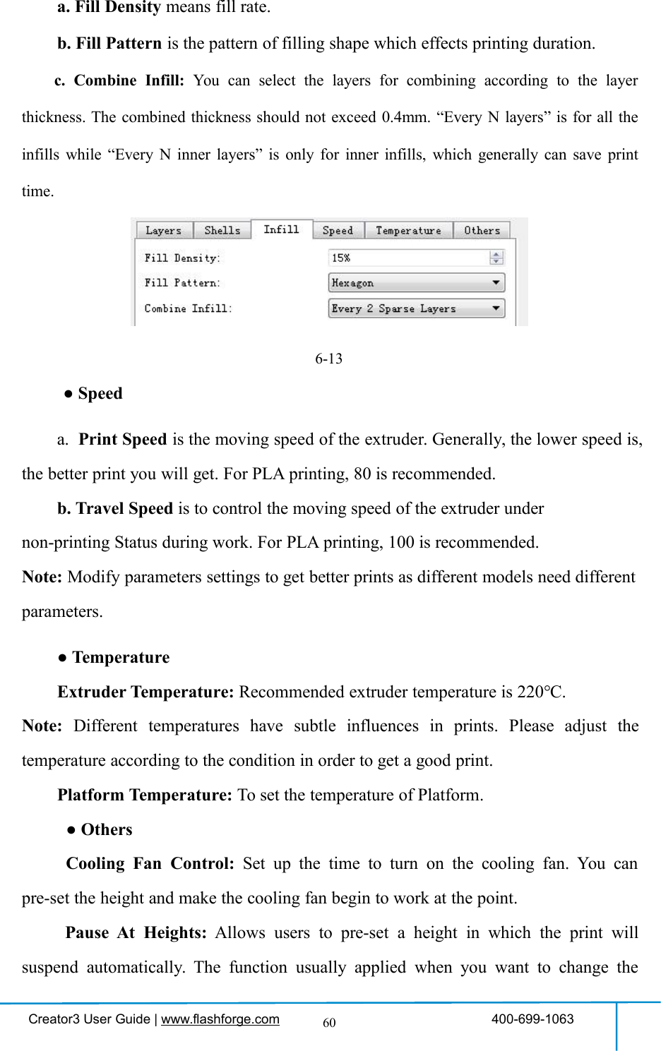
![Creator3 User Guide | www.flashforge.com 400-699-106359④Supports: When print suspended structure models, support is necessary. Click[supports] to create support part for the printing.⑤Raft: This function will help the model to stick well on the platform.⑥Wall: During dual color printing, this function will help to clear the leakingfilament of another extruder.⑦Brim: Expand the outline of model’s bottom layers to a Brim which helps anchorthe edges of the model to the plate to avoid warping.⑧Resolution:You have three resolution solutions (with default setting)to choose from,high resolution is corresponding with slow printing speed, opposite for the lowresolution. For PLA printing, an extra solution “Hyper” is available.⑨More options: Click [More options] to set for layer, shell, infill, speed andtemperature. Different resolution solution is corresponding to different defaults, click[Restore Defaults] to back to default setting.●Layera. Layer: Layer thickness of the printing model. With a small value, the surfaceof the model will be smoother.b. First Layer Height: This is the first layer of the model, which will affect thesticking performance between the model and platform. Maximum is 0.4mm, usuallythe default is OK.c. Shell: Contains the outside shell value, capping layer value (under vase pattern,top solid layer setting is invalid.)● Perimeter Shells: Maximum is 10a. Top Solid Layer: Maximum is 30, minimum is 1.b. Bottom Solid Layer: Maximum is 30, minimum is 1.● Infill](https://usermanual.wiki/Zhejiang-Flashforge-3D-Technology/CREATOR3/User-Guide-4089072-Page-59.png)
![Creator3 User Guide | www.flashforge.com 400-699-106361filament at a certain point.6-14(6-14) Click [Edit], then you can add or remove a height.6.2.11 File Menus①New ProjectClick [File]--[New Project]can build a blank project. If there is an unsavedmodification on previous project, then it will inform you whether the modificationneeds to be saved or not. Click [Yes]will save the modification, while click [No]willabandon it. If click [Cancel]or close tool tip, then will cancel the new project.②SavingAfter finishing the model edit and adjustment, there are two ways below to save allmodels in the scene.Method 1:Click [File]--[Save Project] in the menu bar to save the file as a project file with the“.fpp” suffix, all models in the scene (include support) are independent. After](https://usermanual.wiki/Zhejiang-Flashforge-3D-Technology/CREATOR3/User-Guide-4089072-Page-61.png)
![Creator3 User Guide | www.flashforge.com 400-699-106362reloading the files, extruder configuration information and model position will be thesame as the configuration during saving.Method 2:Click on [File]--[Save as...] to save the model as project file .fpp or .stl and .obj.For .stl and .boj, models are integrated as one(include support part). If load it again,only the position of the model was saved, not included the printing parameters.③PreferencesClick [File]--[Preferences], you can choose language and if needs detecting updatewhen start.●Language: The software supports several languages, namely, Chinese (simplifiedChinese and traditional Chinese), English, French, Korean, Japanese and so on.●Font Size: Set the font size.●Check for Update after start up: It is used to preset if it is necessary to activate theonline automatic update function, if choose yes, every time when you open software, itcan online detect if it is a new version software, once new version found, it willreminds users to download and install new version firmware.●Auto layout newly-imported model: Set Yes or No.●Preferred Extruder: Right/Left Extruder.●Printing Window Type: Including Basic Mode and Expert Mode6-16](https://usermanual.wiki/Zhejiang-Flashforge-3D-Technology/CREATOR3/User-Guide-4089072-Page-62.png)
![Creator3 User Guide | www.flashforge.com 400-699-1063636.2.12 Edit Menus①UndoAllows users to undo the recent edits by the following two methods:Method 1: Click [Edit]--[Undo].Method 2: Press the shortcut Ctrl+Z.②RedoAllows users to redo the most recent edit you have undone to your model file by thefollowing two methodsMethod 1: Click [Edit]--[Redo]Method 2: Press the shortcut Ctrl+Y.③Empty Undo-stackTo clean up the recorded operating steps so as to release the memory.④Select AllBy the following two methods, you could select all models in the scene. (Whenmodels are too small to be seen or out of viewing scope, please click [Center] and[Scale] buttons to adjust the model.)Method 1: Click [Edit]--[Select All].Method 2: Press the shortcut Ctrl+A.⑤DuplicateSelect the object and duplicate the object through the following two methods:Method 1: Click [Edit]--[Duplicate]Method 2: Press the shortcut Ctrl+D⑥DeleteSelect the object and delete the object through the following two methods:](https://usermanual.wiki/Zhejiang-Flashforge-3D-Technology/CREATOR3/User-Guide-4089072-Page-63.png)
![Creator3 User Guide | www.flashforge.com 400-699-106364Method 1: Click [Edit]--[Delete]Method 2: Press the shortcut Delete⑦Auto Layout AllClick [Edit]--[Auto Layout All]after loading one or more than one models, allmodels will be placed automatically as automatic placement rule.⑧Repair ModelsClick [Edit]--[Repair Models] to repair models.⑨SupportsClick [Edit]--[Supports] to enter supports setting interface.6.2.13 Print Menus①Connect MachineYou can connect the Creator3 with your PC via Ethernet Cable or WiFi.Note: The machine icon on the bottom right displays the connection status:ConnectedDisconnectedMethod 1:Connect Via Ethernet Cablea. Connect your Creator3 with your PC via an Ethernet cable.b. Turn on your Creator3 and start FlashPrint.c. Click [Print]--[Connect Machine],then select Ethernet in the [Connection Mode]option and select machine you want to connect in [Select Machine] option. If you cannot find your machine, click the [Rescan] button to scan your machine and select it.Finally click [Connect] button to connect to the printer. If you still can not find yourmachine after rescan, it means you haven’t installed the driver in the software.](https://usermanual.wiki/Zhejiang-Flashforge-3D-Technology/CREATOR3/User-Guide-4089072-Page-64.png)
![Creator3 User Guide | www.flashforge.com 400-699-106365Method 2:Connect Via WiFi①Connect Creator3 with your PC under AP modea.Turn on your Creator3b. Tap [Tools]-[Setting]-[WLan hotspot]-[WLan hotspot ON].c. Click on the wireless network setting in your computer, and find the wirelesssignal-“Creator3”. Click [Connect] to connect your computer with Creator3 via Wlanhotspot.d. Click [Print]-[Connect Machine] on FlashPrint. Then the following dialogbox pops up. You need to select “Wi-Fi” in Connect Mode. Enter into the IP Addressshown on the interface and then click [Connect].If successfully connected, you will see the following mark on the right corner.②Connect Creator3 with your PC under STA modea. Tap [Tools]-[Setting]-[WiFi]-[WiFi ON] to turn on the WiFi of Creator3 andconnect your computer and Creator3 with the same WiFi signal.b. Click [Print]-[Connect Machine] on FlashPrint. Then the following dialogbox pops up. You need to select “Wi-Fi” in Connect Mode. Enter into the IP Addressshown on the interface and then click [Connect].](https://usermanual.wiki/Zhejiang-Flashforge-3D-Technology/CREATOR3/User-Guide-4089072-Page-65.png)
![Creator3 User Guide | www.flashforge.com 400-699-106366If successfully connected, you will see the following mark on the right corner.Disconnect Creator3Click [Print]--[Disconnect] to disconnect your PC and Creator3.6.2.14 Help Menus①First Run Wizard②Help Contents:Click [Help]--[Help Contents], you can read the help contents.③Check for Updates :Click [Help]--[Check for Update] to detect the availableupdates online.④About FlashPrint :Click [Help]--[About FlashPrint], the software informationbox will pop up. The contents include the current software version and copyrightinformation.](https://usermanual.wiki/Zhejiang-Flashforge-3D-Technology/CREATOR3/User-Guide-4089072-Page-66.png)
![Creator3 User Guide | www.flashforge.com 400-699-106367Chapter 7: Basic PrintingThis chapter will provide a step-by-step guide on turning a 3D model into a physicalreality. Before proceeding, it is recommended that you’d better go over prior chapterson loading/unloading filament, leveling the build platform, and the functions andcapabilities of FlashPrint.7.1 Generate a Gcode(7-1) Double-click the icon of FlashPrint to start the software.7-1(7-2) Click [Print]--[Machine Type] to select FlashForge Creator37-2(7-3)Click the [Load] icon to load a .stl model file and the object will display on thebuild area.7-3(7-4)Click [Edit]--[Surface to Platform] to make your model perfectly positioned34](https://usermanual.wiki/Zhejiang-Flashforge-3D-Technology/CREATOR3/User-Guide-4089072-Page-67.png)
![Creator3 User Guide | www.flashforge.com 400-699-106368on the build area. Click [Back] and double-click the Move icon again, then click [Onthe Platform] and [Center] to ensure the model be on the platform.7-4Note:If you’ve place your model in a right place, you can skip the step above.(7-5) Click the [Print] icon on the top, you should make some setups for your printjob.](https://usermanual.wiki/Zhejiang-Flashforge-3D-Technology/CREATOR3/User-Guide-4089072-Page-68.png)
![Creator3 User Guide | www.flashforge.com 400-699-106369Preview: If you check the [Preview] box, you can preview your model after slicing isdone.Print When Slice Done: If you print via USB cable, you can check the box, while ifyou print via USB, you should not check the box.Machine Type: FlashForge Creator3Material Right: Choose the right extruder filament material.Material Left: Choose the left extruder filament material.Supports: If you print a model with supports, you should click the inverted triangleand select [Enable].Raft: You are suggested to select [Enable].Resolution: You are suggested to select [Standard]More Options: You are suggested to keep them default.Click [OK] to select the path to save the Gcode file. You can rename the file as youlike and save it as a .g or .gx file, click [Save] to generate a Gcode file.Note: .gx files are available for preview while the .g files are not. They are displayingas follows:g. Files gx. FilesNext, we are going to print the model.](https://usermanual.wiki/Zhejiang-Flashforge-3D-Technology/CREATOR3/User-Guide-4089072-Page-69.png)
![Creator3 User Guide | www.flashforge.com 400-699-1063707.2 Print MethodsAfter generating the Gcode file, you can transfer it to your Creator3. You can transferthe file through Ethernet Cable or WiFi or USB stick.7.2.1 Print from Computer ( Ethernet Cable connection)①Connect your Creator3 with your PC via a Ethernet cable.(Please refer to 6.2.13 )②Turn on your Creator3, level the build plate and load the filament.③Click [Print]and transfer your Gcode file to your Creator3. After completingtransference, the printer will heat up automatically. And when heating finishes, theprinter will start to build the model.④When your PC connects with FlashPrint successfully. The status box on thebottom right displays the real-time nozzle temperature. After finishing preheating,your Creator3 starts the print job directly.7.2.2 Print from Computer (WiFi connection)①Connect your Creator3 with your PC via WiFi. (Please refer to 6.2.13 )Enter into the IP Address shown on your Creator3 interface and then click [Connect].](https://usermanual.wiki/Zhejiang-Flashforge-3D-Technology/CREATOR3/User-Guide-4089072-Page-70.png)
![Creator3 User Guide | www.flashforge.com 400-699-106371②Turn on your Creator3, level the build plate and load the filament.③Click [Print]and transfer your Gcode file to your Creator3. After completingtransference, the printer will heat up automatically. And when heating finishes, theprinter will start to build the model.If you want to print a Gcode from a local folder, you just need to load the file intoFlashPrint at the status of Ethernet connection or WiFi connection, then click the[Print] button on the top-right.●Load the target Gcode file into FlashPrint.7-9●Click the [Print] button, the PC will transfer the Gcode file to the printer.](https://usermanual.wiki/Zhejiang-Flashforge-3D-Technology/CREATOR3/User-Guide-4089072-Page-71.png)
![Creator3 User Guide | www.flashforge.com 400-699-1063727-10● After finishing transferring, the printer will heat up automatically. And when heatingfinishes, the print will start to build the model.7.2.3 Print from USB Stick①Insert your USB stick with target .g or .gx file to your Creator3. .②Turn on the Creator3. Make sure the build plate has been leveled and the filament isloaded.③Tap [Print] and then tap the USB Stick icon in the middle. The file(s) will bedisplayed on the screen. Select the file you want to print and tap [Print]. The file willbe transferred to the printer.⑥And the printer will heat up the nozzle automatically and start to print after thenozzle reaches the aimed temperature.Abort:To stop heating and printing. Once you tap [Abort], the process is irreversible.Pause:To suspend the print job, you can tap it again to resume it. You can use thisfunction when you want to change the filament halfway.7-11](https://usermanual.wiki/Zhejiang-Flashforge-3D-Technology/CREATOR3/User-Guide-4089072-Page-72.png)