Zhejiang Flashforge 3D Technology GUIDERII 3D Printer User Manual
Zhejiang Flashforge 3D Technology CO., Ltd. 3D Printer Users Manual
UserManual.wiki
>
Zhejiang Flashforge 3D Technology
>
GUIDERII User Manual
Users Manual
Navigation menu
Upload a User Manual
Namespaces
Wiki Guide
HTML
PDF
Info
Views
User Manual
Discussion / Help
Navigation
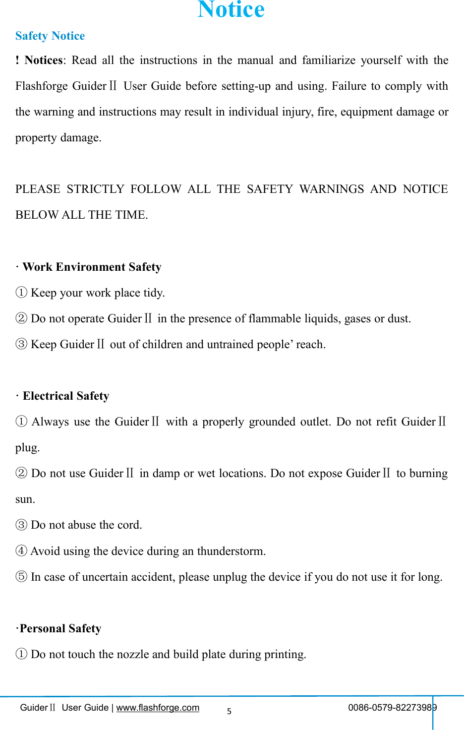
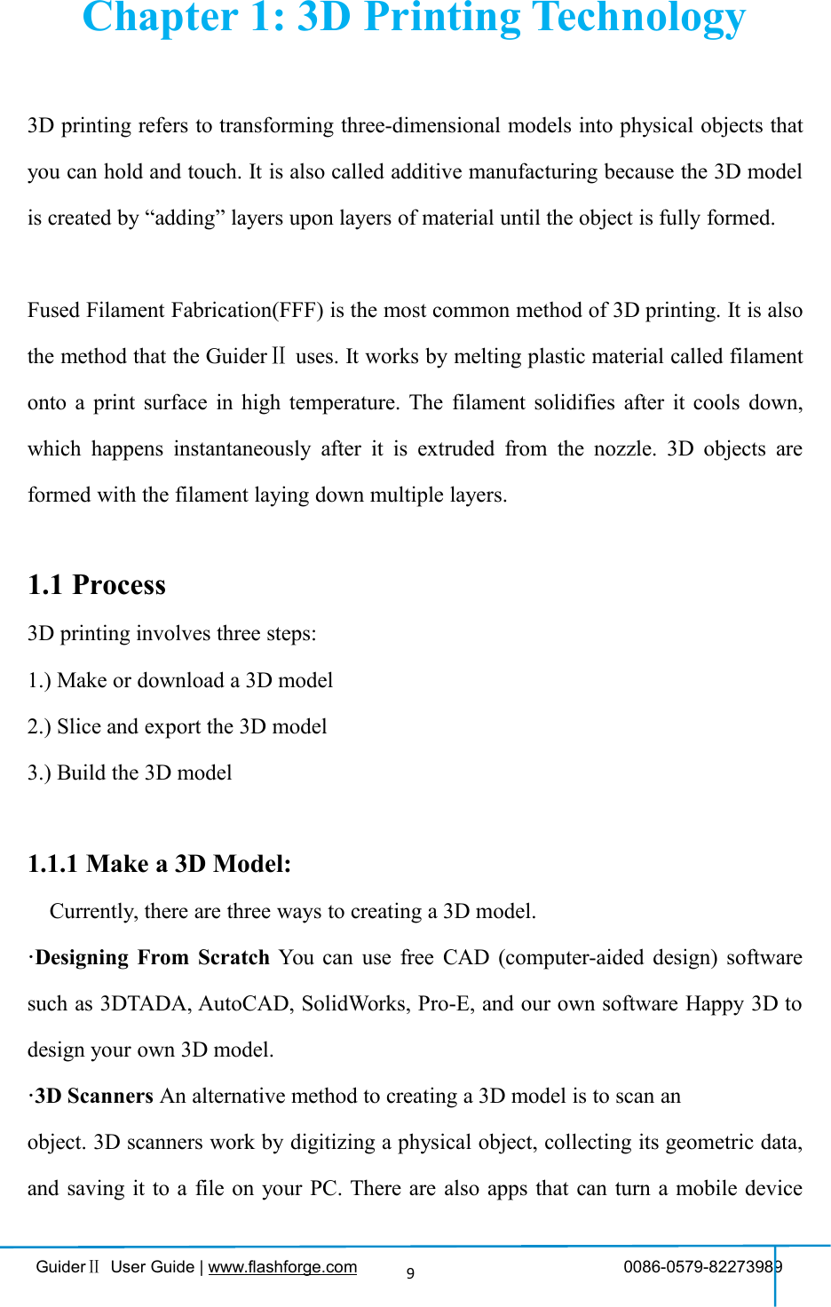
![GuiderⅡUser Guide | www.flashforge.com 0086-0579-8227398915Tools in print interfaceFilament: To change filament duringprinting.(Note: You need to suspend the operationfirst)Finish-Shutdown: To start auto shutdownCancel: To end the tool orders and returnto the print interface.PreheatTap the [Preheat] button to enter the preheatinterface. Tap the [Start] button to heat up tothe setting temperature.The default temperature is 220℃.Tap the temperature display bar to set thetemperature.To set the preheat temperature.Tap [Yes] to save the setting while tap [No]to cancel the setting.](https://usermanual.wiki/Zhejiang-Flashforge-3D-Technology/GUIDERII/User-Guide-3474824-Page-15.png)
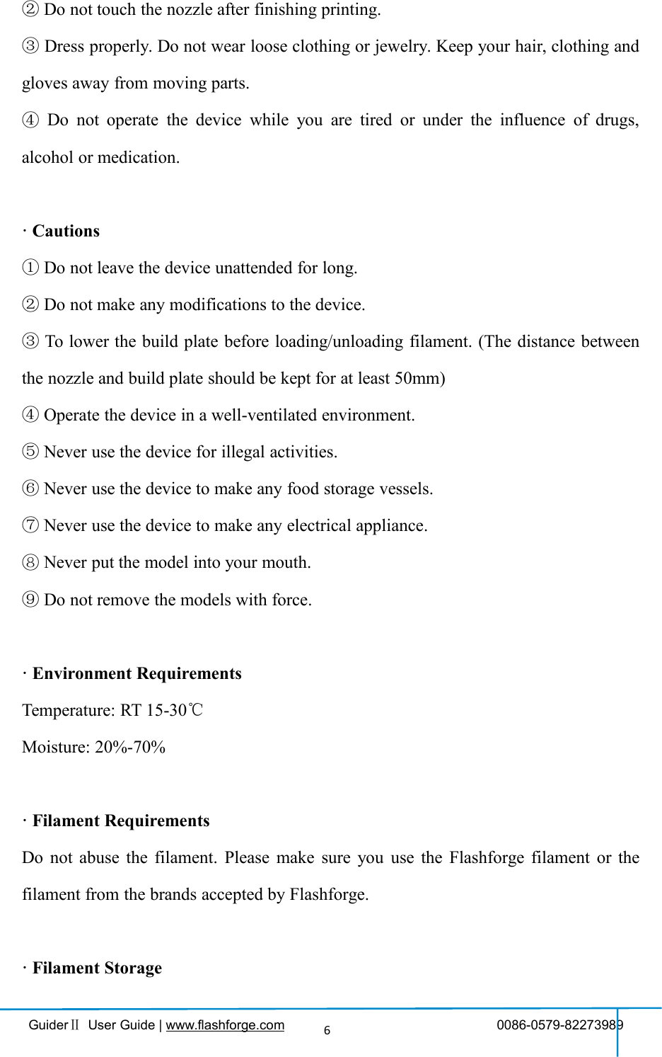
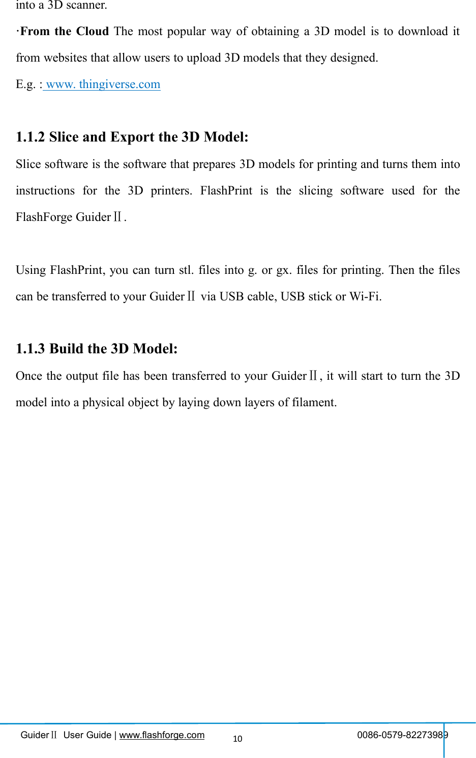
![GuiderⅡUser Guide | www.flashforge.com 0086-0579-8227398916The picture displays the preheat interface. Itshows the actual temperature and the targettemperature. Tap the [Abort] button to abortthe preheat job.ToolsTap [Tools] to enter tool options.Filament: To load/unload the filament.Level: To adjust the build plate.Home: To make the X, Y and Z axes backto the zero point.Manual: To manually adjust the positionsof X, Y and Z axes.Setting: To implement relevant functionsetups.Status: The check the real-time status ofthe printer.About: Information about the printer.Return arrowManual adjustmentY+: The extruder moves to the zero point,that is, the back of the machineY-: The extruder moves to the directionopposite to the Y+.X+: The extruder moves to the zeropoints, that is, to the right directionX-: The extruder moves to the directionopposite to the X+.Z+: The build plate elevates.Z-: The build plate descends.Return arrow](https://usermanual.wiki/Zhejiang-Flashforge-3D-Technology/GUIDERII/User-Guide-3474824-Page-16.png)
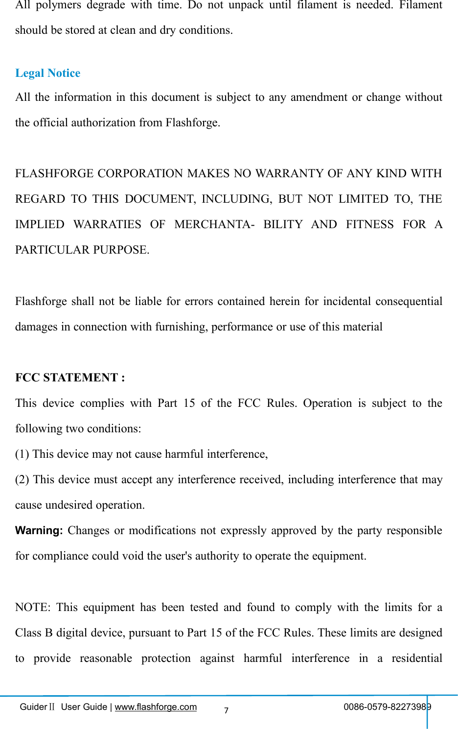
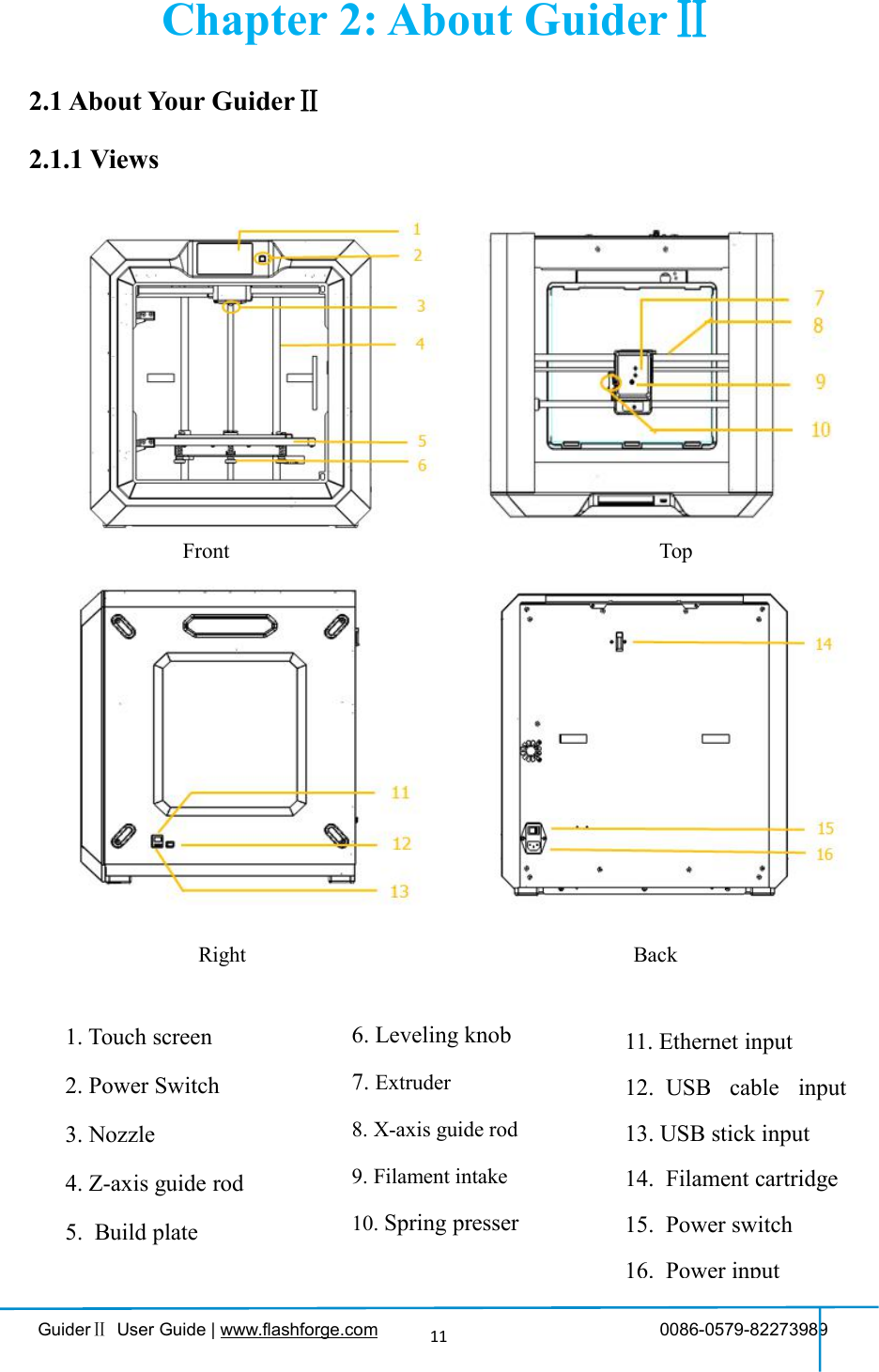
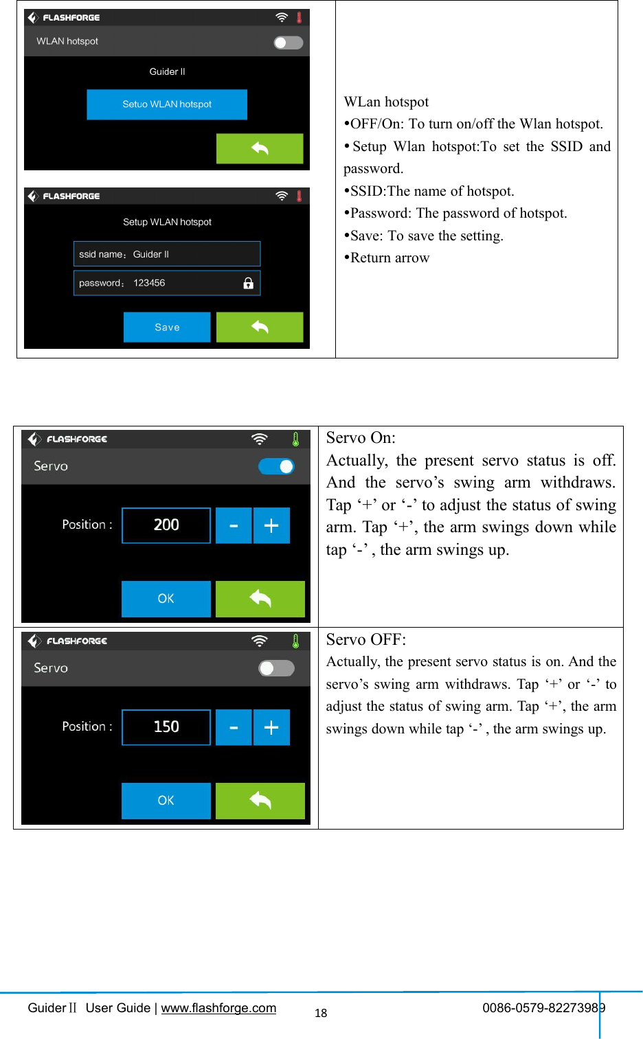
![GuiderⅡUser Guide | www.flashforge.com 0086-0579-8227398917Tap [Setting] to enter the setting interfaceLanguage: To set the display languageResume Print: Resume print afterrestarting Guider IIWLAN: To turn on/off the WlanWlan hotspot: To turn on/off the Wlanhotspot.Servo Calibration: To turn on/off theservo or adjust the servo.Extruder Calibration: To adjust the initialdistance between the extruder and thebuild plate.Filament Check Off: To turn on/off thefilament checkFactory Reset:return to factory settingUpdate: To update the firmware version.Return arrowWIFI:Turn on WIFI: Turn on the WIFI, releasethe WIFI hotspot and set the WIFI oncomputerReturn arrow](https://usermanual.wiki/Zhejiang-Flashforge-3D-Technology/GUIDERII/User-Guide-3474824-Page-17.png)

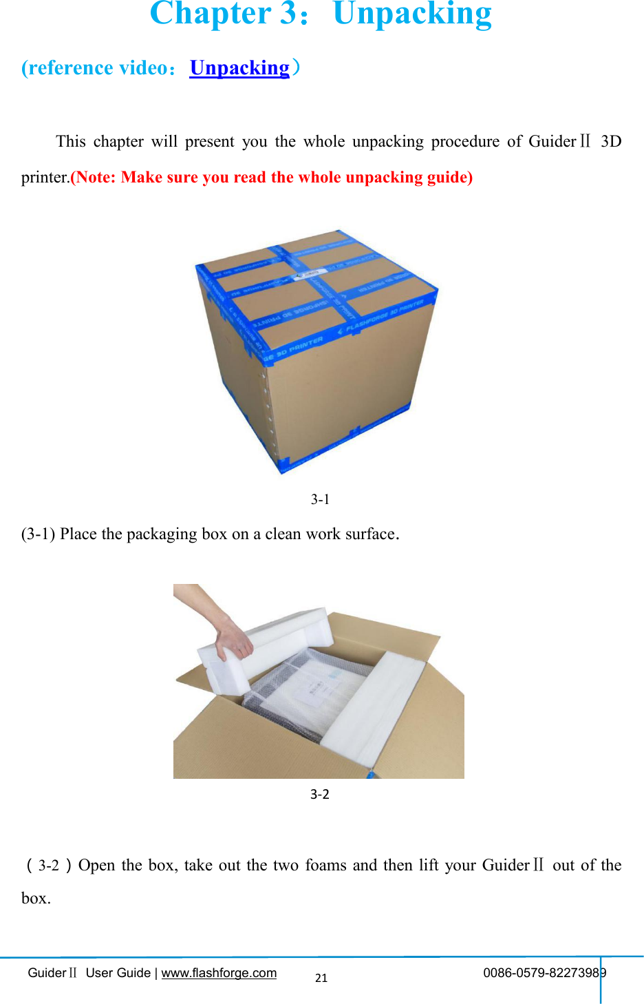
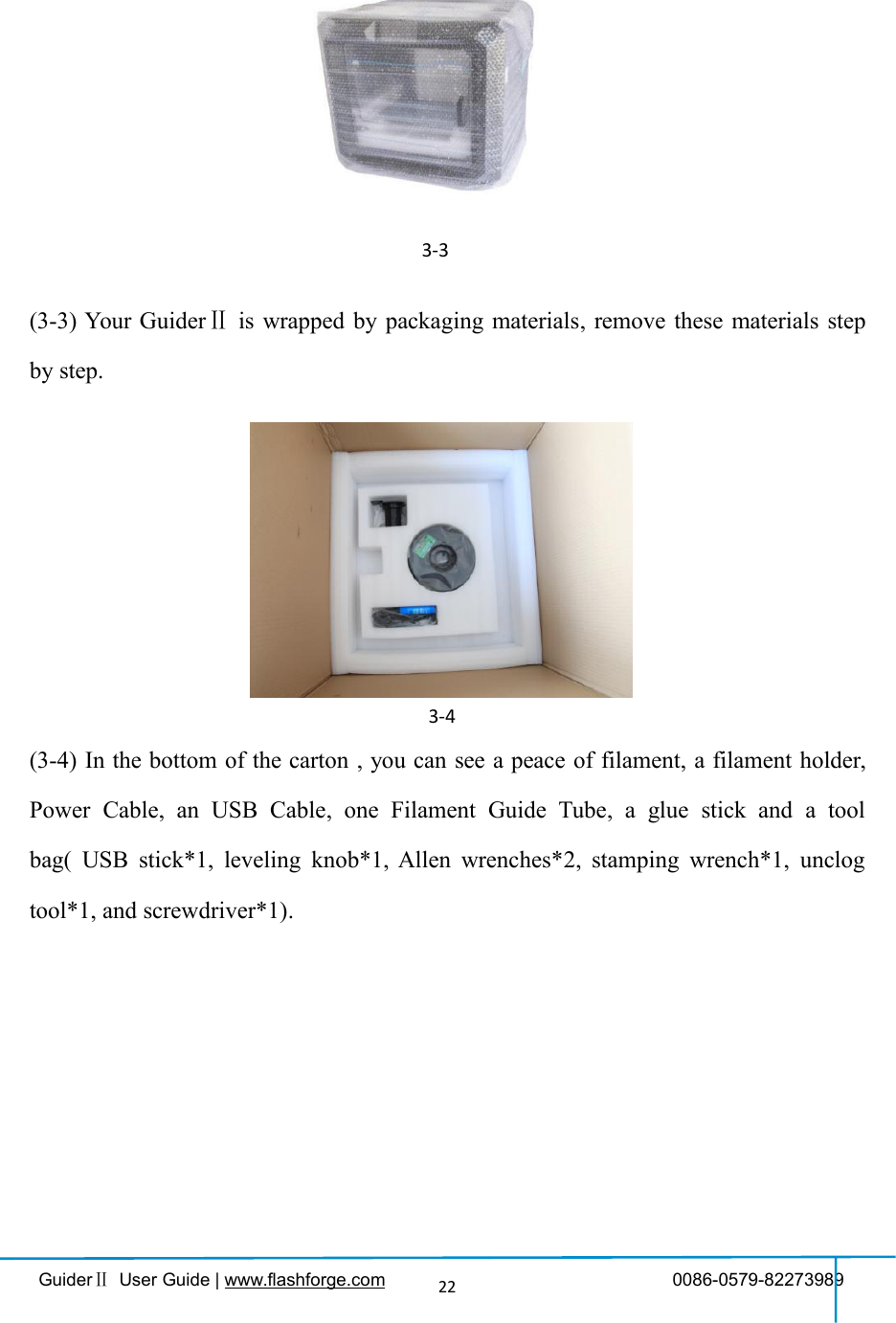
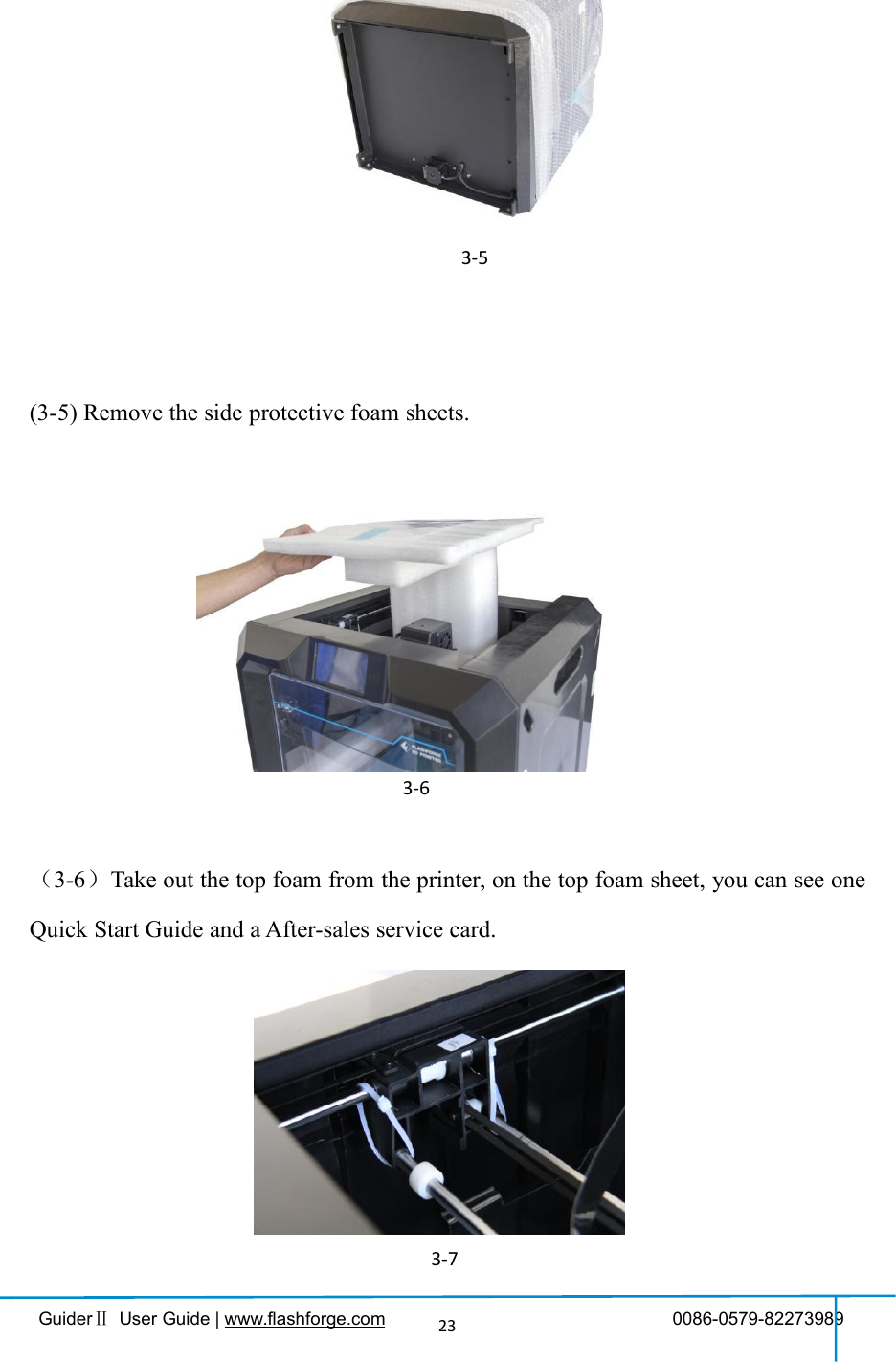
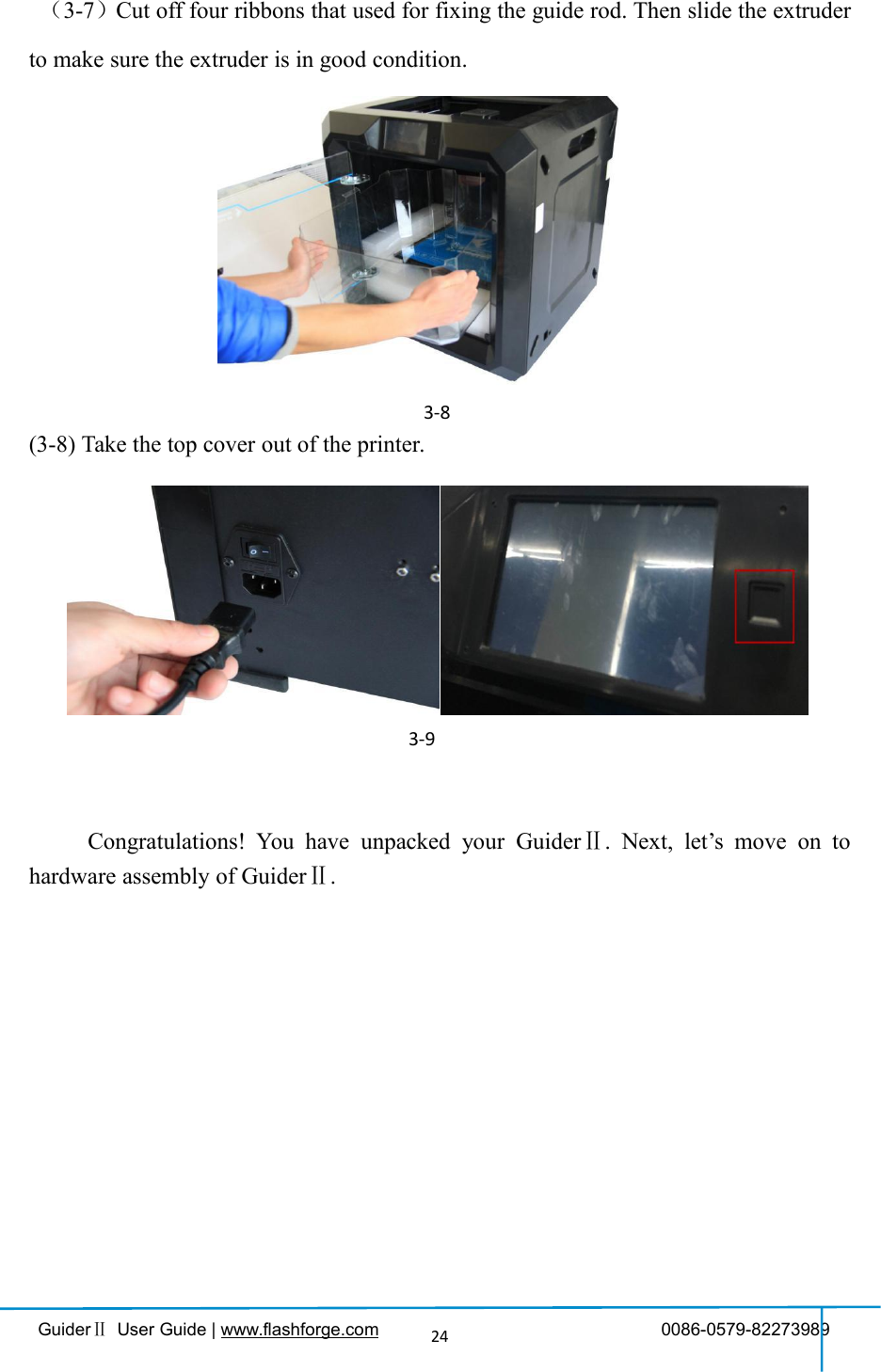
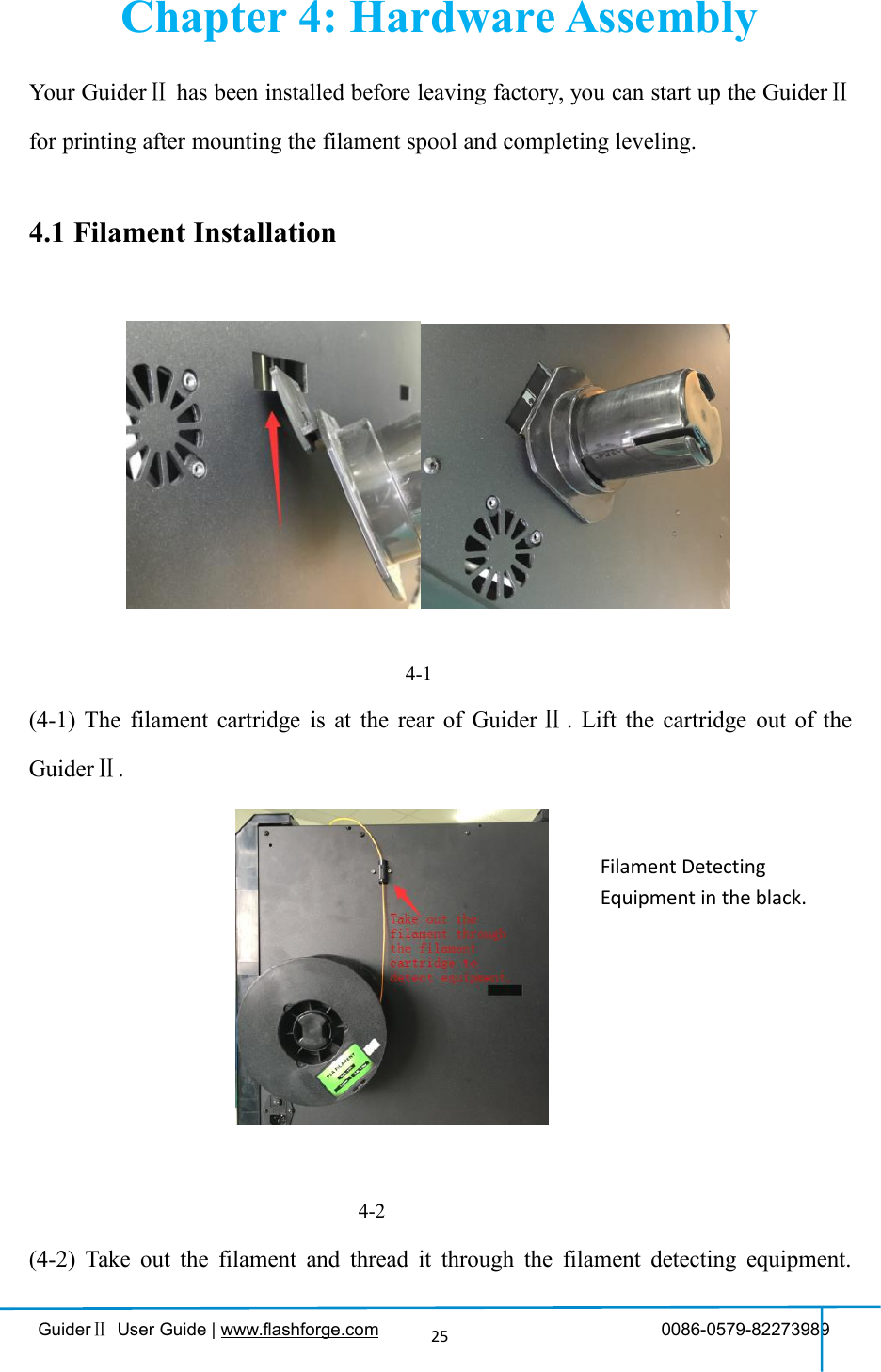
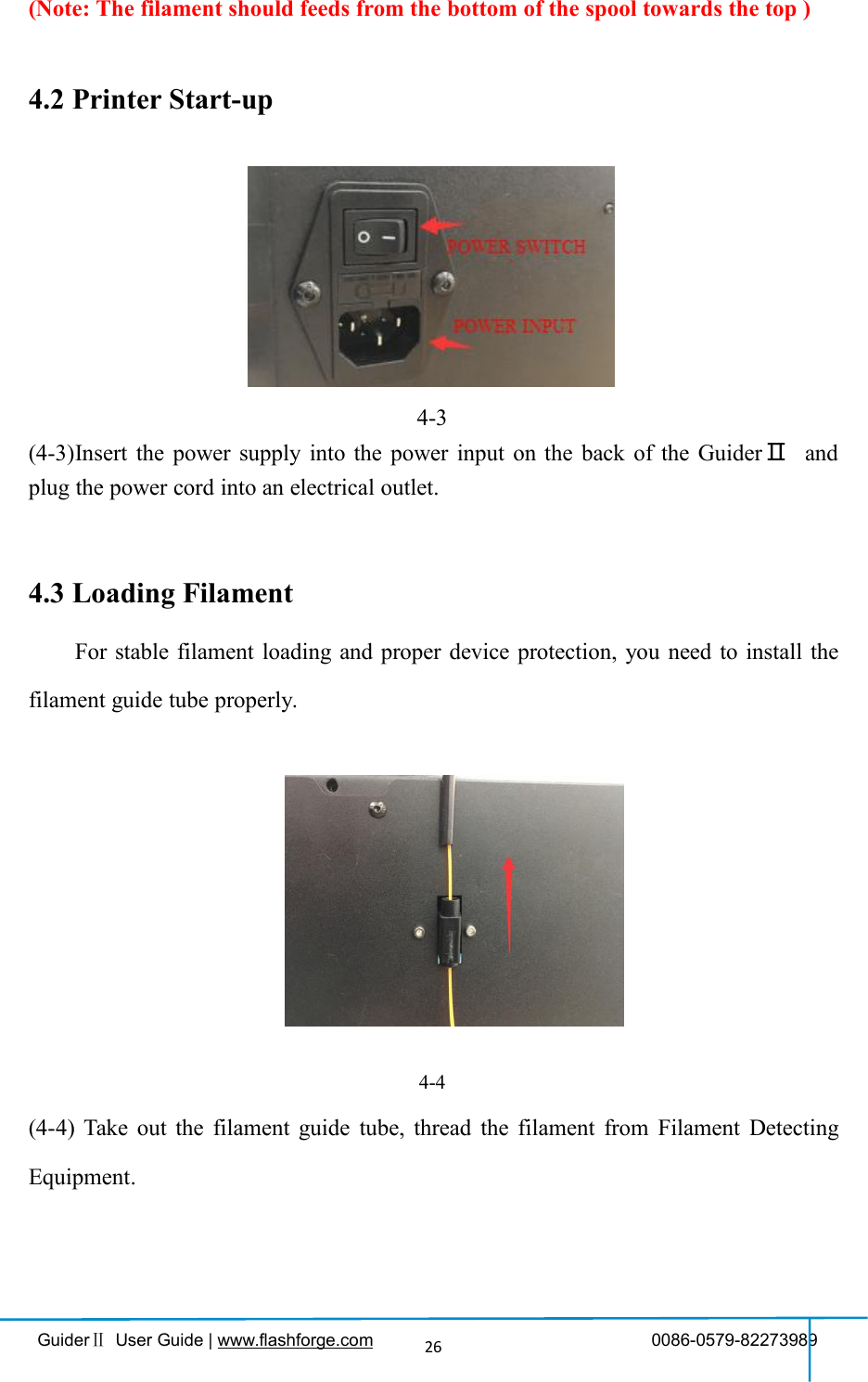
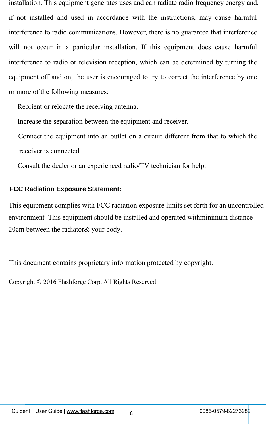
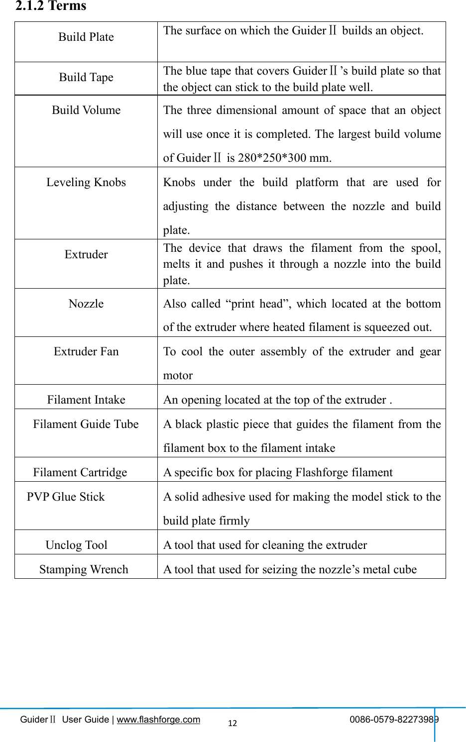
![GuiderⅡUser Guide | www.flashforge.com 0086-0579-8227398927(4-6) Insert the filament from the filament guide tube into the filament intake.Next, we will load the Flashforge filament.(Note: Please lower the build plate toincrease the distance between the nozzle and build plate to 50mm at least foravoiding nozzle jam.)(4-7) Tap [Tool].图4-64-8(4-8) Tap [Filament]--[Load]4-74-6](https://usermanual.wiki/Zhejiang-Flashforge-3D-Technology/GUIDERII/User-Guide-3474824-Page-27.png)
![GuiderⅡUser Guide | www.flashforge.com 0086-0579-82273989284-9(4-9)After the extruder’s temperature reaches 220℃, the printer will sound a beep toprompt you to load the filament into the extruder.4-10(4-10)Insert the filament into the extruder at an upright angle. Then the filament willbe drawn through the extruder. Do not tap [Cancel] until the filament load the extrudersteadily.](https://usermanual.wiki/Zhejiang-Flashforge-3D-Technology/GUIDERII/User-Guide-3474824-Page-28.png)
![GuiderⅡUser Guide | www.flashforge.com 0086-0579-82273989294.4 Unloading Filament4-11(4-11) Tap [Tool]-[Unload] and the extruder starts heating up.4-12(4-12) After the extruder reaches 220℃, the printer will sound a beep to prompt you tounload the filament from the extruder. Press the spring presser, press down thefilament for about three seconds and gently pull the filament out.Note: Do not pull out the filament with force as it will damage the gears. If themelted filament has cooled down in the extruder, please repeat the steps above.](https://usermanual.wiki/Zhejiang-Flashforge-3D-Technology/GUIDERII/User-Guide-3474824-Page-29.png)
![GuiderⅡUser Guide | www.flashforge.com 0086-0579-8227398930Chapter 5: Build Plate LevelingGuider Ⅱcreatively adopts three-point intelligent leveling system, which will giveclear and comprehensive feedback to users. There are three spring-loaded knobs underthe build platform. The distance between the plate and nozzle increases whiletightening the knobs. On the contrary, the distance reduces.(5-1) Tap [Tools] - [Level] on your Guider Ⅱtouch screen. Please wait while theextruder and platform finish initial movements. After that, operate according to theguide on the touch screen.5-2(5-2) After tapping [Yes], the extruder starts to move towards the first point and the5-1](https://usermanual.wiki/Zhejiang-Flashforge-3D-Technology/GUIDERII/User-Guide-3474824-Page-30.png)
![GuiderⅡUser Guide | www.flashforge.com 0086-0579-8227398931plate moves up and down to verify the distance between nozzle and plate.5-3(5-3) When it shows that the distance is too big, please unscrew corresponding nutunder platform clockwise until hearing a steady beep and the [Verify] button appears.5-4(5-4) If the distance is appropriate, tap [OK] to second point leveling. If still not,please follow the prompts to adjust again till you see [OK] button.5-5(5-5) Repeat steps 2 through 4 above to complete second and third points leveling andthen Tap [Finish] to exit.](https://usermanual.wiki/Zhejiang-Flashforge-3D-Technology/GUIDERII/User-Guide-3474824-Page-31.png)
![GuiderⅡUser Guide | www.flashforge.com 0086-0579-8227398932Leveling Emergency Plan:Some leveling spare parts may be damaged after being used for a period of time.Now users could adopt the emergency plan for leveling.(1)Insert the USB stick to the USB port.(2)Tighten each of the three knobs underneath the build platform until they go nofurther(3)Tap [Build] on the touch screen, tap the USB icon and then select Leveling.gfile.(4)Tap [Build], then the build plate and the extruder start moving.(5)After they stop moving, you can adjust the distance between the build plate andthe nozzle manually. Move the extruder to the position right over the front-left knob,and adjust the knob individually. Use a A4 paper to check the distance. As you adjustthe knob, make sure the paper just slides between the nozzle and build plate. Therewill be somewhat friction on the paper but still can easily pass the paper between theplate and the nozzle without tearing or damaging the paper.(6)Then move to the positions right over the right-front and rear knobs successively,and then adjust the distance according to the descriptions above.(7)Then move to the center of the build plate for a check. Confirm that the paperslides between the nozzle and build with a moderate amount friction.(8)Tap the Abort button and finish leveling.](https://usermanual.wiki/Zhejiang-Flashforge-3D-Technology/GUIDERII/User-Guide-3474824-Page-32.png)
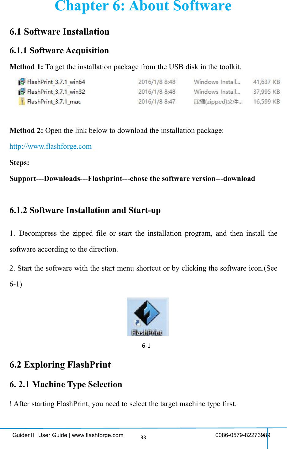
![GuiderⅡUser Guide | www.flashforge.com 0086-0579-8227398934When you start FlashPrint, a dialog box will pop up. Just select Flashforge GuiderⅡin the machine type list and click [OK]. You can also change the machine type viaclicking [Print]--[Machine type]. See graphic 6-2:6-26.2.2 Software IntroductionLoad one or multiple files.Enter the support edit mode6-3](https://usermanual.wiki/Zhejiang-Flashforge-3D-Technology/GUIDERII/User-Guide-3474824-Page-34.png)
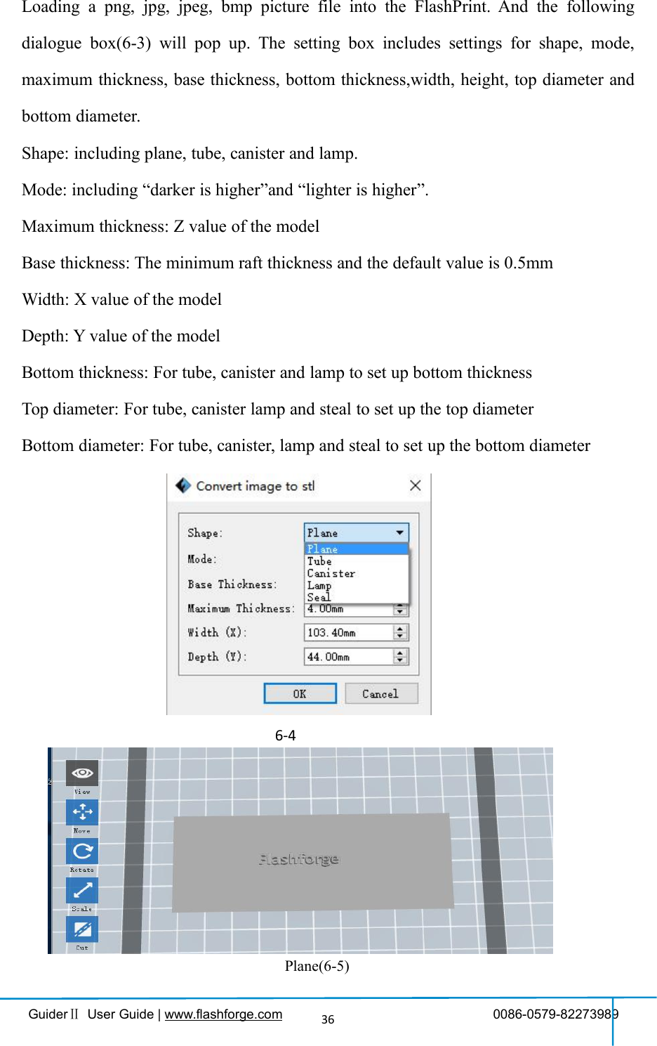
![GuiderⅡUser Guide | www.flashforge.com 0086-0579-8227398935Print it directly with your GuiderⅡor export to your USB StickView FlashPrint home screen from one of six viewing anglesMove model around on xy-plane; shift+click to move along z axisTurn and rotate your modelScale the size of your objectCut model into several parts6.2.3 LoadingYou can load a model file or Gcode file into your Flashprint by the following sixmethods:Method 1: Click the Load icon on the main interface. Then select the objectfile.Method 2: Select the file for loading and drag the file to the main interface of thesoftware.Method 3: Click [File]--[Load File]. Then select the object file for loading.Method 4: Click [File]--[Examples]to load the example filesMethod 5: Click [File]--[Recent Files]to load the files opened recently.Method 6: Select and drag the target file to the icon of Flashprint.Note: .STL, .OBJ, and .FPP,ways to store 3D models, are supported by Flashprintfor editing.Generating Rilievo](https://usermanual.wiki/Zhejiang-Flashforge-3D-Technology/GUIDERII/User-Guide-3474824-Page-35.png)
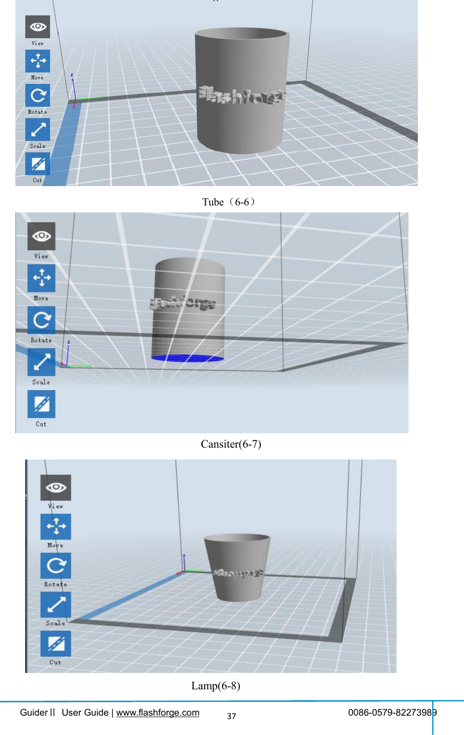
![GuiderⅡUser Guide | www.flashforge.com 0086-0579-8227398938Seal(6-9)6.2.4 Views①Changing viewsChange model views by moving, rotating, scaling.●DragClick the [View] icon and then you can move the object by the following threemethods:Method 1: Hold down the left mouse button and drag.Method 2: Hold down the middle mouse button and drag.Method 3: Hold down the Shift key, hold down the right mouse button and drag.●RotateClick the [View] icon and then you can rotate the object by the following twomethods:Method 1. Hold down the right mouse button and drag.Method 2. Hold down the Shift key, hold down the left mouse button and drag.●ScaleRotate the mouse wheel to enlarge or shrink the build plate.](https://usermanual.wiki/Zhejiang-Flashforge-3D-Technology/GUIDERII/User-Guide-3474824-Page-38.png)
![GuiderⅡUser Guide | www.flashforge.com 0086-0579-8227398939②Set ViewAllows users to view the object on the build plate. Six views are under the view menu,that is, home view, bottom view, top view, front view, back view, left view and rightview.Method 1: Click the the [View] button, there are six views in the drop- down listMethod 2: Click the the [Look] icon on the left, click it again and a submenuwill appear with six views for selecting.③Reset ViewAllow users to reset views by the following two methods:Method 1: Click the [View] menu and select [Home View]Method 2: Click the [View]button on the left, click it again and you will see theviewing options, you can click [Reset].④Show Model OutlineClick [View]--[Show Model Outline], it will highlight the yellow border of the object⑤Show Steep OverhangClick [View]--[Show Steep Overhang]. When the intersection angle between themodel surface and horizontal line is within the overhang threshold value, the surfacehas steep overhang and it becomes red in the software. Overhang threshold valuecould be set as needed. The default value is 45 degree.6.2.5 MoveSelect the object and move the object by the following two methods:](https://usermanual.wiki/Zhejiang-Flashforge-3D-Technology/GUIDERII/User-Guide-3474824-Page-39.png)
![GuiderⅡUser Guide | www.flashforge.com 0086-0579-8227398940Method 1: Click the [Move] icon on the left, hold down the left mouse button anddrag to adjust the location of the model in XY direction. Hold down the Shift key,hold down the left mouse button and drag to adjust the location of the model in Zdirection. The distance and the direction of the movement shall be displayed.Method 2: Click the [Move]button on the left and then enter the distance value. Click[Reset]to reset distance values.Note: Users shall click [Center] and [On Platform] after the location adjustment toensure the model(s) be within the build area and on the build platform. If a specifiedposition is needed, only to click [On Platform].6.2.6 RotateSelect the target object and rotate the object by the following two methods:Method 1: Click the [Rotate] icon on the left and three mutually perpendicular ringsappear around the object Click one ring and rotate on the present axis, you will see therotation angle and direction in the center of circle. In this way, you could make themodel rotate on X/Y/Z axis.Method 2: Click the [Rotate] icon on the left, and then enter into rotating angelvalues in X/Y/Z axes positioning. Click [Reset] to reset rotating angel values.6.2.7 ScaleSelect the target object and scale the object by the following two methods:Method 1: Click the [Scale] icon on the left, hold down the left mouse button andscale the model. The corresponding values will display near the object.Method 2: Click the [Scale] icon on the left and then enter into scale values in X/Y/Zaxes positioning. Click the [Maximum] button to get largest size possible for building.Click [Reset] to reset the size of model.](https://usermanual.wiki/Zhejiang-Flashforge-3D-Technology/GUIDERII/User-Guide-3474824-Page-40.png)
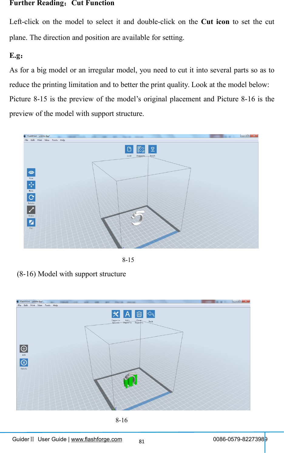
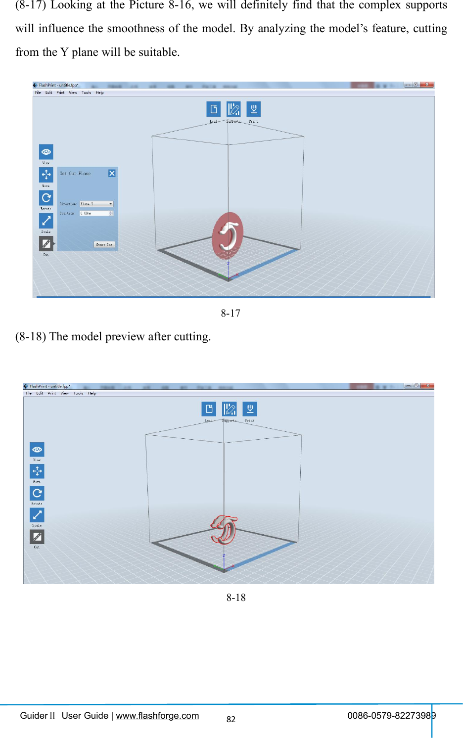
![GuiderⅡUser Guide | www.flashforge.com 0086-0579-8227398941Note: If the [Uniform Scaling] radio button is clicked, it will scale the model in equalproportion when changing value in any positioning of the model. Otherwise it willonly change the value of the corresponding positioning.6.2.8 CutLeft-click on the model to select it and double-click on the Cut icon to set the cutplane. The direction and position are available for setting.①Draw with Mouse②X Plane③Y Plane](https://usermanual.wiki/Zhejiang-Flashforge-3D-Technology/GUIDERII/User-Guide-3474824-Page-41.png)
![GuiderⅡUser Guide | www.flashforge.com 0086-0579-8227398942④Z Plane6.2.9 SupportsAfter loading the model, click [Edit]--[Supports]or click the Supports icon directly,then you will enter the support edit mode(as shown in the picture below). Click [Back]to exit when you finish editing.6-10①Support OptionsClick the Support Options, an option box will appear, supports options include“treelike”and “linear”, when choose “treelike”, click [OK], then it will generatetreelike structure; when choose “linear”, click [OK], then it will generate linearstructure; if it is a model with supports, when you choose one of the supports options,software will judge whether existing supports need to be deleted or not on the basis of](https://usermanual.wiki/Zhejiang-Flashforge-3D-Technology/GUIDERII/User-Guide-3474824-Page-42.png)
![GuiderⅡUser Guide | www.flashforge.com 0086-0579-8227398943the type of existing support, and will pop up the corresponding prompt to let you makethe choice.②Auto SupportsClick the [Auto Supports] button, the software will judge the position where supportsare needed and generate corresponding treelike or linear supports. If it is a model withsupports, the existing supports will be deleted and new supports will be generated.③Add SupportsSupports will be added once clicking the [Add]button. Move the cursor to theposition where supports needed, left-click to choose the starting point of supports, holddown the left mouse button and drag the mouse the supports preview will show up(ifsupport surface doesn’t need support or the support column angle is too large, willhighlight the support review ). Loosen the left mouse button, if support columndoesn’t meet with model, then support will be generated on origin and terminalpoint(the highlighted preview support won’t generate support structure )6-11](https://usermanual.wiki/Zhejiang-Flashforge-3D-Technology/GUIDERII/User-Guide-3474824-Page-43.png)
![GuiderⅡUser Guide | www.flashforge.com 0086-0579-8227398944④Clear SupportsClick [Clear Supports], all supports will be deleted. The operation can be repealedvia clicking [Undo]or pressing the shortcut key Ctrl+Z.⑤Delete SupportsSupports will be deleted once clicking the [Delete]button. Move the cursor to thesupports needed deleting, current supports and its subnode support will be highlighted,click the left mouse button to delete these highlighted support.6.2.10 Print①Preview: Choose to enter preview interface or not②Print when slice done: Print or not when slice done③Material type: Choose according to the type of model6-12](https://usermanual.wiki/Zhejiang-Flashforge-3D-Technology/GUIDERII/User-Guide-3474824-Page-44.png)
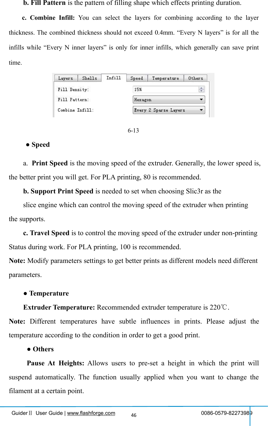
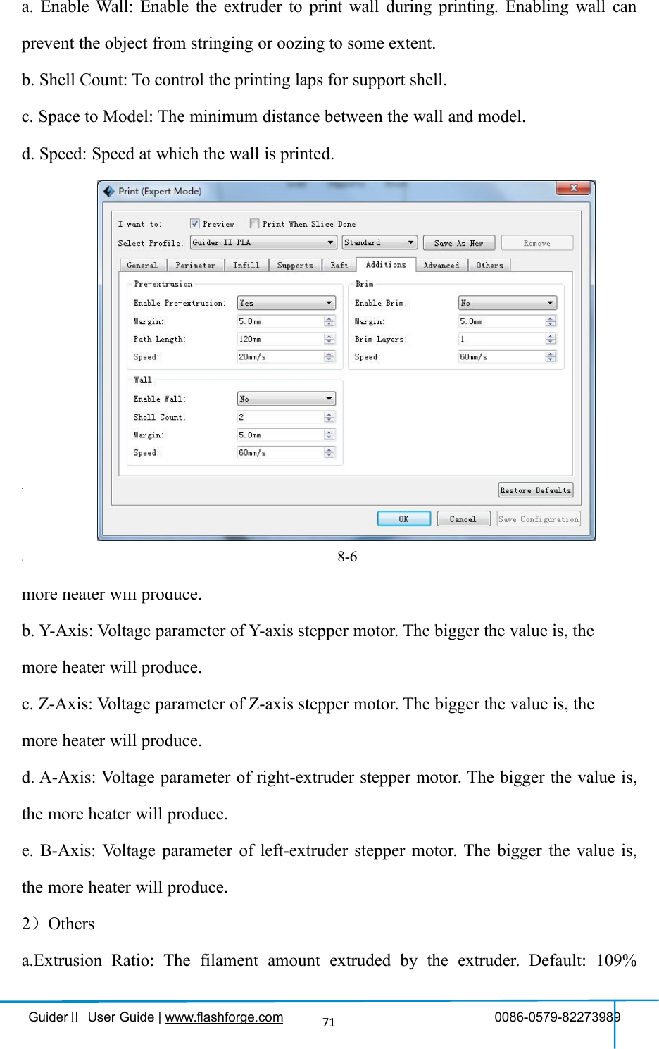
![GuiderⅡUser Guide | www.flashforge.com 0086-0579-8227398945④Supports: When print suspended structure models, support is necessary. Click[supports] to create support part for the printing.⑤Raft: This function will help the model to stick well on the platform.⑥Wall: During dual color printing, this function will help to clear the leakingfilament of another extruder.⑦Vase Mode: No capping for the model⑧Resolution:You have three resolution solution(with default setting)to choose from,high resolution is corresponding with slow printing speed, opposite for the lowresolution. For PLA printing, an extra solution “Hyper” is available.⑨More options: Click [More options] to set for layer, shell, infill, speed andtemperature. Different resolution solution is corresponding to different defaults, click[Restore Defaults] to back to default setting.●Layera. Layer: Layer thickness of the printing model. With a small value, the surfaceof the model will be more smooth.b. First Layer Height: This is the first layer of the model, which will affect thesticking performance between the model and platform. Maximize is 0.4mm, usuallythe default is ok.c. Shell: Contains the outside shell value, capping layer value (under vase pattern,top solid layer setting is invalid.)● Primeter Shells: Maximize is 10a. Top Solid Layer: Maximize is 10, minimum is 1.b. Bottom Solid Layer: Maximize is 10, minimum is 1.● Infilla. Fill Density means fill rate.](https://usermanual.wiki/Zhejiang-Flashforge-3D-Technology/GUIDERII/User-Guide-3474824-Page-45.png)
![GuiderⅡUser Guide | www.flashforge.com 0086-0579-8227398947(6-14) Click[Edit], then you can add or remove a height.6.2.11 File Menus①New ProjectClick [File]--[New Project]can build a blank project. If there is an unsavedmodification on previous project, then it will inform you whether the modificationneeds to be saved or not. Click [Yes]will save the modification, click [No]willabandon it. If click [Cancel]or close tool tip, then will cancel the new project.②SavingAfter finishing the model edit and adjustment, there are two ways below to save allmodels in the scene.Method 1:Click [File]--[Save Project] in the menu bar to save the file as a project file with the“.fpp”suffix, all models in the scene (include support) are independent . Afterreloading the files, extruder configuration information and model position will be thesame as the configuration during saving.6-156-14](https://usermanual.wiki/Zhejiang-Flashforge-3D-Technology/GUIDERII/User-Guide-3474824-Page-47.png)
![GuiderⅡUser Guide | www.flashforge.com 0086-0579-8227398948Method 2:Click on [File]--[Save as...] to save the model as project file .fpp or .stl and .obj.For .stl and .boj, models are integrated as one(include support part). If load it again,only the position of the model was saved, not included the printing parameters.③PreferencesClick [File]--[Preferences], you can choose language and if needs detecting updatewhen start●Language: The software supports six languages, namely, Chinese(simplifiedChinese and traditional Chinese), English, French, Korean, Japanese and Russian.●Printing Window Type: Including Base Mode and Expert Mode●Check for Update after start up: It is used to preset if it is necessary to activate theonline automatic update function, if choose yes, every time when you open software, itcan online detect if it is a new version software, once new version found, it willreminds users to download and install new version firmware.6.2.12 Edit Menus①UndoAllows users to undo the recent edits by the following two methods:Method 1: Click [Edit]--[Undo].6-16](https://usermanual.wiki/Zhejiang-Flashforge-3D-Technology/GUIDERII/User-Guide-3474824-Page-48.png)
![GuiderⅡUser Guide | www.flashforge.com 0086-0579-8227398949Method 2: Press the shortcut Ctrl+Z.②RedoAllows users to redo the most recent edit you have undone to your model file by thefollowing two methodsMethod 1: Click [Edit]--[Redo]Method 2: Press the shortcut Ctrl+Y.③Empty Undo-stackTo clean up the recorded operating steps so as to release the memory.④Select AllBy the following two methods, you could select all models in the scene. (Whenmodels are too small to be seen or out of viewing scope, please click [Center] and[Scale] buttons to adjust the model.)Method 1: Click [Edit]--[Select All].Method 2: Press the shortcut Ctrl+A.⑤DuplicateSelect the object and duplicate the object through the following two methods:Method 1: Click [Edit]--[Duplicate]Method 2: Press the shortcut Ctrl+D⑥DeleteSelect the object and delete the object through the following two methods:Method 1: Click [Edit]--[Delete]Method 2: Press the shortcut Delete⑦Surface to Platform](https://usermanual.wiki/Zhejiang-Flashforge-3D-Technology/GUIDERII/User-Guide-3474824-Page-49.png)
![GuiderⅡUser Guide | www.flashforge.com 0086-0579-8227398950After selecting the model, you can make the model surface to platform via thefollowing operation.Click [Edit]--[Surface to Platform]into surface to platform mode(Asshown in the picture)(Surface to Platform)⑧Auto Layout AllClick [Edit]--[Auto Layout All]after loading one or more than one models, allmodels will be placed automatically as automatic placement rule.6.2.13 Print Menus①Connect MachineYou can connect the GuiderⅡwith your PC via a USB cable or WIFI.Note: The machine icon on the bottom right displays the connection status:Connected6-17](https://usermanual.wiki/Zhejiang-Flashforge-3D-Technology/GUIDERII/User-Guide-3474824-Page-50.png)
![GuiderⅡUser Guide | www.flashforge.com 0086-0579-8227398951DisconnectedMethod 1:Connect Via USB Cablea. Connect your GuiderⅡwith your PC via an USB cable.b. Turn on your GuiderⅡand start Flashprint.c.Click [Print]--[Connect Machine],then select USB in the [Connection Mode]option and select machine you want to connect in [Select Machine] option. If you cannot find your machine, click the [Rescan] button to scan your machine and select it.Finally click [Connect] button to connect to the printer. If you still can not find yourmachine after rescan, it means you haven’t installed the driver in the software.6-18Method 2:Connect Via WIFI①Connect GuiderⅡwith your PC under AP modea.Turn on your GuiderⅡb.Tap [Tools]-[Setting]-[WIFI]-[WIFI ON]c. Click on the wireless network on the left bottom, and find the wirelesssignal-“GuiderⅡ”. Click [Connect] to finish network connection.d. Click[Print]-[Connect Machine] on Flashprint. Then the following dialog box](https://usermanual.wiki/Zhejiang-Flashforge-3D-Technology/GUIDERII/User-Guide-3474824-Page-51.png)
![GuiderⅡUser Guide | www.flashforge.com 0086-0579-8227398952pops up. You need to select “Wi-Fi” in Connect Mode. Enter into the IP Addressshown on the interface and then click [Connect].6-19If successfully connected, you will see the following red mark.②Connect GuiderⅡwith your PC under STA modea. Turn on the WIFI of Guider Ⅱand connect your PC with GuiderⅡvia theWIFI. Press [ Tools ],[ Setting ],[ WIFI ], and [ WIFI ON].b.“GuiderⅡ” continuous signal will be found available on the network list.c. Once your PC is connected with your GuiderⅡ. Open the Internet browser andenter “10.10.100.254” and enter the default user name(admin) andpassword(admin).6-20](https://usermanual.wiki/Zhejiang-Flashforge-3D-Technology/GUIDERII/User-Guide-3474824-Page-52.png)
![GuiderⅡUser Guide | www.flashforge.com 0086-0579-8227398953You will enter the WIFI setting panel, it displays as follows:6-21d. Select WIFI mode as STA mode, and then complete the corresponding setups, youcan change the SSID(the WIFI’s name) and the password, select [Enable] in DHCPauto get IP, then click [Save]. The following interface will appear.6-22e. Click the [Restart] button. You need to restart your Guider Ⅱ’s WIFI. And then](https://usermanual.wiki/Zhejiang-Flashforge-3D-Technology/GUIDERII/User-Guide-3474824-Page-53.png)
![GuiderⅡUser Guide | www.flashforge.com 0086-0579-8227398954your GuiderⅡwill connect with your computer via the WIFI that you’ve set up.②Disconnect GuiderⅡClick [Print]--[Disconnect] to disconnect your PC and GuiderⅡ.6.2.14 Tool Menus①Control PanelAfter connecting PC with Guider Ⅱ, click [Tools]--[Control Panel] to open thecontrol panel.6-23●Jog Controlsa. Jog Mode:Select the distance that extruder/ build plate move a single time (that is,the distance extruder/ build plate move upon your single click).b. Six blue arrow direction button: Control the move along X/Y/Z axis. X/Y axisbutton control extruder move, Z axis button control build plate move. Click X-,extruder will move leftward a specified distance; Click X+, extruder will move aspecified distance rightward. Click Y-, extruder will move forward a specified distance;Click Y-, extruder will move backward a specified distance. Click Z-, build plate will](https://usermanual.wiki/Zhejiang-Flashforge-3D-Technology/GUIDERII/User-Guide-3474824-Page-54.png)
![GuiderⅡUser Guide | www.flashforge.com 0086-0579-8227398955move upward a specified distance; Click Z-, build plate will move downward aspecified distance. (Specified distance refers to the move distance you set in JogMode.c. Stop: Click the [stop] button to abort the current movement. d. XYZ coordinateframe on the right side: Show the current position of extruder/build plate.e. Make Current Position Zero button: Set the current position of theextruder/build plate as (0, 0, 0). (NOTE: X, Y, and Z boxes are for display purposes.Changing the value in the boxes will not affect anything.f. Center X/Y/Z button: Extruder and build platform will back to the zero (0, 0, 0)you set last time.g. X/Y Speed and Z Speed: Set the move speed of extruder/ build platform.●Limit Switch: In order to protect your GuiderⅡ, three limit switches are equippedto control the maximum position, and the three limit switches corresponding to X/Y/Zaxis limit switch. It has two status:a. Not Triggered: If the extruder/build plate don’t move to its maximum, X/Y/Z axislimit switch is not triggered, and shows “Not Triggered”.b. Triggered: If the extruder/build plate moves to its maximum, X/Y/Z axis limitswitch is triggered, and shows “Triggered”.●Stepper Motor Controls: Allows users to control to stepper motor. Click [Enable],and lock the motor so it does not allow any movement; click [Disable], and unlock themotor to be controlled manually.●LED Color: Allows users to change the LED color of GuiderⅡ.●Extruder Controls: You can set the value of “Motor Speed(RPM)”, which cancontrol the rotation speed of filament feeding wheel. The motor rotation time can becontrolled via setting the value of “Extruder Duration”.Generally we suggest theusers choose option of continuous time 60 seconds. The filament must loaded in the](https://usermanual.wiki/Zhejiang-Flashforge-3D-Technology/GUIDERII/User-Guide-3474824-Page-55.png)
![GuiderⅡUser Guide | www.flashforge.com 0086-0579-8227398956extruder before motor starts. Therefore, do not start rotation operation until theextruder temperature reaches to the printing temperature of filament. For PLAfilament, the extruder temperature should reach 200℃, after reaching the extrudertemperature, click the [Forward]/[Reverse] rotation button to control filament loadand filament unload. Furthermore, if you want to stop filament load and unload, youcan click [Stop].●Temperature Control: Input the temperature you want to get in the left frame, click[Apply], the printer will automatically heat the corresponding part, the right sideshows the current actual temperature of corresponding part. After starting heating, thebelow curve of temperature form will start to change, different color corresponddifferent parts’ temperatures②Update FirmwareEvery time when you start Flashprint, it will automatically detect and download theup-to-date firmware. If any update is available, a dialog box will pop up for remindingthe users to update.Step 1: Click [Tools]--[Update firmware]. It needs to cut off connection beforeupdating firmware. If software and printer are already in connection, it reminds youcutting off the connection, choose [Yes] and go on to the next step.Step 2: Choose corresponding printer type and firmware version and click [OK] in thefirmware updating box. After confirming the printer is in free state, the software willautomatically update the firmware](https://usermanual.wiki/Zhejiang-Flashforge-3D-Technology/GUIDERII/User-Guide-3474824-Page-56.png)
![GuiderⅡUser Guide | www.flashforge.com 0086-0579-82273989576-24Step 3:Reboot you GuiderⅡand wait for 4-5 seconds, then you can see the updateprocess bar. When the update finishes, it will go back to the main interface.Step 4:Tap[Tools]--[About] to check] to check whether the updated version is right.③On Board PreferencesWhen the computer and printer are in connection, click [Tools]--[On BoardPreferences], you can check the printer name.④Machine informationWhen the computer and printer are in connection state, click [Tools]--[Machineinformation], you can check the machine type, machine name and firmware etc.6.2.15 Help Menus①Help Contents:Click [Help]--[Help Contents], you can read the help contents.②Check for Updates :Click [Help]--[Check for Update] to detect the availableupdates online.③About FlashPrint :Click [Help]--[About Flashprint], the software information](https://usermanual.wiki/Zhejiang-Flashforge-3D-Technology/GUIDERII/User-Guide-3474824-Page-57.png)

![GuiderⅡUser Guide | www.flashforge.com 0086-0579-8227398959Chapter 7: Basic PrintingThis chapter will provide a step-by-step guide on turning a 3D model into a physicalreality. Before proceeding, it is recommended that you’d better go over prior chapterson loading/unloading filament, leveling the build platform, and the functions andcapabilities of FlashPrint.7.1 Generate a Gcode(7-1)Double-click the icon of Flashprint to start the software.7-1(7-2)Click[Print]--[Machine Type] to select Flashforge GuiderⅡ7-2(7-3)Click the [Load] icon to load a .stl model file and the object will display on thebuild area.7-3(7-4)Click [Edit]--[Surface to Platform] to make your model perfectly positioned34](https://usermanual.wiki/Zhejiang-Flashforge-3D-Technology/GUIDERII/User-Guide-3474824-Page-59.png)
![GuiderⅡUser Guide | www.flashforge.com 0086-0579-8227398960on the build area. Click [Back] and double-click the Move icon again, then click [Onthe Platform] and [Center] to ensure the model be on the platform.7-4Note:If you’ve place your model in a right place, you can skip the step above.(7-5) Click the Print icon on the top, you should make some setups for your print job.Preview: If you check the [Preview] box, you can preview your model after slicing isdone.7-5](https://usermanual.wiki/Zhejiang-Flashforge-3D-Technology/GUIDERII/User-Guide-3474824-Page-60.png)
![GuiderⅡUser Guide | www.flashforge.com 0086-0579-8227398961Print When Slice Done: If you print via USB cable, you can check the box, while ifyou print via USB, you should not check the box.Machine Type: Flashforge GuiderⅡSupports: If you print a model with supports, you should click the inverted triangleand select [Enable].Raft: You are suggested to select [Enable].Resolution: You are suggested to select [Standard]More Options: You are suggested to keep them default.Click [OK] to select the path to save the Gcode file. You can rename the file as youlike and save it as a .g or .gx file, click [Save] to generate a Gcode file.Note: .gx files are available for preview while the .g files are not. They are displayingas follows:g. Files gx. Files7-7Next, we are going to print the model.7.2 Print MethodsAfter generating the Gcode file, you can transfer it to your GuiderⅡ. You can transferthe file through USB cable and USB stick.7.2.1 Print from Computer (USB connection)①Connect your GuiderⅡwith your PC via a USB cable.②Turn on your GuiderⅡ, level the build plate and load the filament.](https://usermanual.wiki/Zhejiang-Flashforge-3D-Technology/GUIDERII/User-Guide-3474824-Page-61.png)
![GuiderⅡUser Guide | www.flashforge.com 0086-0579-8227398962③Click [Print]and transfer your Gcode file to your GuiderⅡ. After completingtransference, the printer will heat up automatically. And when heating finishes, theprint will start to build the model.7-8④When your PC connects with FlashPrint successfully. The status box on thebottom right displays the real-time nozzle temperature. After finishing preheating,your GuiderⅡstarts the print job directly.7.2.2 Print from Computer (WIFI connection)①Connect your GuiderⅡwith your PC via WIFI.(Please refer to 6.1.13)②Turn on your GuiderⅡ, level the build plate and load the filament.③Click [Print]and transfer your Gcode file to your GuiderⅡ. After completingtransference, the printer will heat up automatically. And when heating finishes, theprinter will start to build the model.If you want to print a Gcode from a local folder, you just need to load the file intoFlashprint at the status of USB connection or WIFI connection, then click the [Print]button on the top-right.●Load the target Gcode file into FlashPrint.](https://usermanual.wiki/Zhejiang-Flashforge-3D-Technology/GUIDERII/User-Guide-3474824-Page-62.png)
![GuiderⅡUser Guide | www.flashforge.com 0086-0579-82273989637-9●Click the [Print] button, the PC will transfer the Gcode file to the printer.7-10● After finishing transferring, the printer will heat up automatically. And when heatingfinishes, the print will start to build the model.](https://usermanual.wiki/Zhejiang-Flashforge-3D-Technology/GUIDERII/User-Guide-3474824-Page-63.png)
![GuiderⅡUser Guide | www.flashforge.com 0086-0579-82273989647.2.3 Print from USB Flash Disk①Insert your USB flash disk with target .g or .gx file to your GuiderⅡ. .②Turn on the GuiderⅡ. Make sure the build plate has been leveled and the filamentis loaded.③Tap [Print] and then tap the SD Card icon in the middle. The file(s) will bedisplayed on the screen. Select the file you want to print and tap [Print]. The file willbe transferred to the printer.⑥And the printer will heat up the nozzle automatically and start to print after thenozzle reaches the aimed temperature.,Abort:To stop heating and printing. Once you tap [Abort], the process is irreversible.Pause:To suspend the print job, you can tap it again to resume it. You can use thisfunction when you want to change the filament halfway.7-11](https://usermanual.wiki/Zhejiang-Flashforge-3D-Technology/GUIDERII/User-Guide-3474824-Page-64.png)
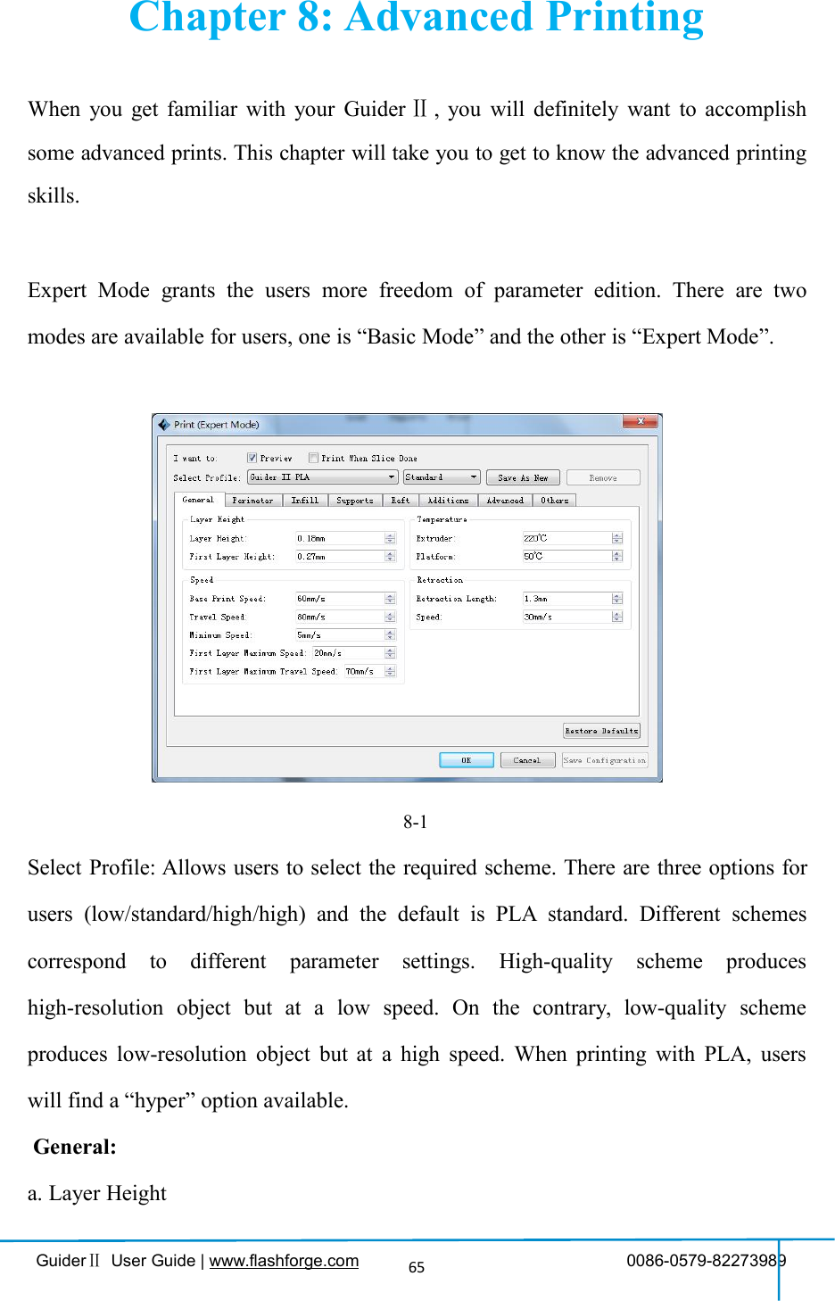
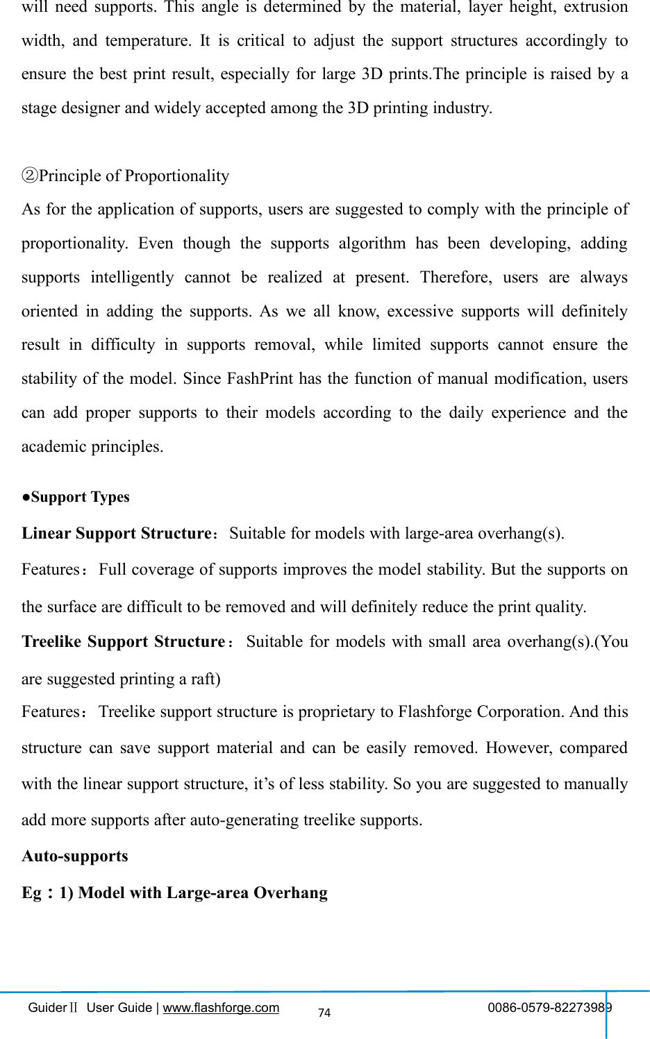
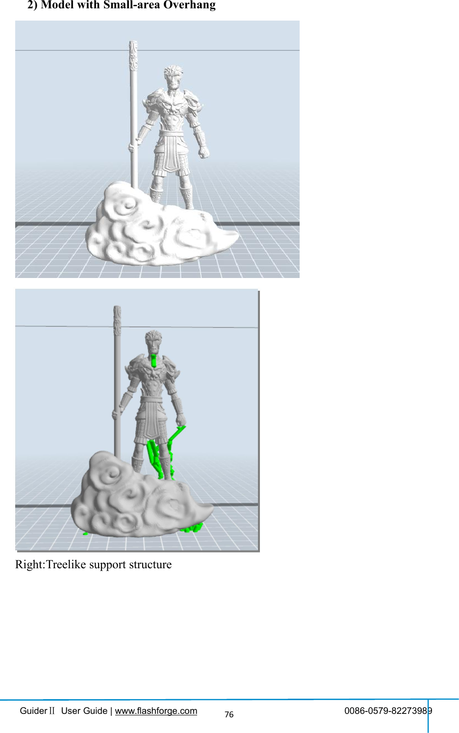
![GuiderⅡUser Guide | www.flashforge.com 0086-0579-8227398973Save as newAllows users to save the model as a new file after parameter modification.How to do?After getting all the required parameters modified, click [Save as new], then adialogue box will pop up. Users need to enter the file name into the box, then click[OK]. Click the drop-down menu of [Select Profile], the new added scheme can befound in the list.RemoveAllows the users to delete the added scheme(s). Select one of the added schemes, click[Remove] and a dialogue box will pop up for confirmation. Click [Yes] to remove it orclick [No] to cancel the current operation.Restore Default: Allows users to restore to the default settings.Save Configuration: Allows users to save the present configuration.8.1 Skills on Supports(Reference Video:Skills on Supports)Support structures enable the printing of models with steep overhangs and cantileveredsections. The Guider Ⅱ3D printer utilizes Fused Filament Fabrication (FFF)technology, which works on the additive manufacturing principle of heating and layingdown material layer by layer to create an object. Many sophisticated 3D print designsrequire materials to be deposited on a layer where there was not a previous layer, orthe designs have steep angles which might cause undesired drooping during the print.In these cases, support structures are needed to ensure objects integrity and printquality.①Principle of 45 DegreesGenerally speaking, if the 3D model has an overhang of more than 45 degrees, you](https://usermanual.wiki/Zhejiang-Flashforge-3D-Technology/GUIDERII/User-Guide-3474824-Page-73.png)
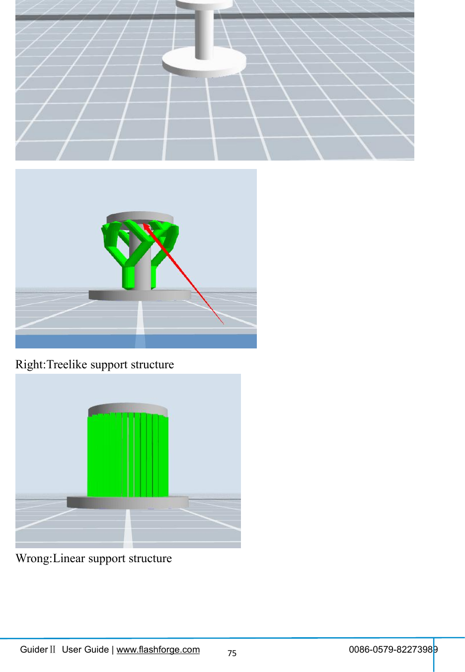
![GuiderⅡUser Guide | www.flashforge.com 0086-0579-8227398977Wrong:Linear support structureManual Modification8-9For the experienced 3D printer users, the [Add] and [Delete] buttons are suggestedusing for manually adding or deleting supports.](https://usermanual.wiki/Zhejiang-Flashforge-3D-Technology/GUIDERII/User-Guide-3474824-Page-77.png)
![GuiderⅡUser Guide | www.flashforge.com 0086-0579-82273989781)Manual Add8-10You can add the support structure manually to according to the actual shape of themodel.Left click [Add] on the left, and then click on the position when support structure is](https://usermanual.wiki/Zhejiang-Flashforge-3D-Technology/GUIDERII/User-Guide-3474824-Page-78.png)
![GuiderⅡUser Guide | www.flashforge.com 0086-0579-8227398979needed. Press down the left mouse button and drag to generate the support.2)Manual Delete8-11Like the picture above, a hole inside the model doesn’t need any supports.Left click the [Delete] button and then left click the supports needed deleting. And thesupport will be deleted.8.2 Control over Printing Quality①Enhance the build plate adhesiveness●Leveling the build plate●Keeping the build plate smooth and tidy● Using the build tape or glue②Adjusting the printing speed●Low (Fast) (Print Speed 80mm/s Travel Speed 100mm/s)●Standard (Print Speed 60mm/s Travel Speed 80mm/s)● High (Slow) (Print Speed 50mm/s Travel Speed 70mm/s)● Hyper (Print Speed 50mm/s Travel Speed 70mm/s)](https://usermanual.wiki/Zhejiang-Flashforge-3D-Technology/GUIDERII/User-Guide-3474824-Page-79.png)
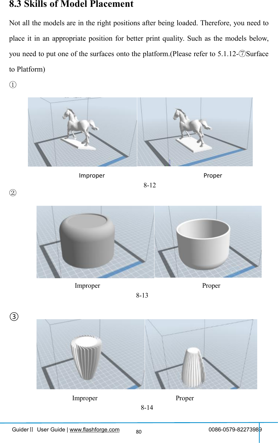
![GuiderⅡUser Guide | www.flashforge.com 0086-0579-8227398983(8-19) Click [Edit]--[Surface to Platform] to put the flat surfaces onto the platform.7-10Comparison8-19](https://usermanual.wiki/Zhejiang-Flashforge-3D-Technology/GUIDERII/User-Guide-3474824-Page-83.png)